GEOVISION 00EFR370000 WLAN USB Module, Ralink IEEE 802.11 b/g/n solution User Manual
GEOVISION INC. WLAN USB Module, Ralink IEEE 802.11 b/g/n solution
user manual

Copyright © JORJIN TECHNOLOGIES INC. LIMITED 2010
CONFIDENTIAL
a module solution provider
WN8020-00 WLAN USB Module
Ralink IEEE 802.11 b/g/n solution
USER MANUAL

Doc No: WN8020-00-SPC-R06
Copyright © JORJIN TECHNOLOGIES INC. LIMITED 2010
CONFIDENTIAL
Page 2
Index
1. OVERVIEW .................................................................................................................... 2
2. ELECTRICAL CHARACTERISTICS ............................................................................. 5
2.1. RF CHARACTERISTICS ................................................................................................. 5
2.2. ABSOLUTE MAXIMUM RATINGS ................................................................................... 5
3. SMT & BAKING RECOMMENDATION ................................................................. 6
3.1. BAKI NG RECOMM ENDATION .................................................................................... 6
3.2. S M T RECOMMENDATION ......................................................................................... 7
4. HISTORY CHANGE ................................................................................................... 9
Doc No: WN8020-00-SPC-R06
Copyright © JORJIN TECHNOLOGIES INC. LIMITED 2010
CONFIDENTIAL
Page 3
1. OVERVIEW
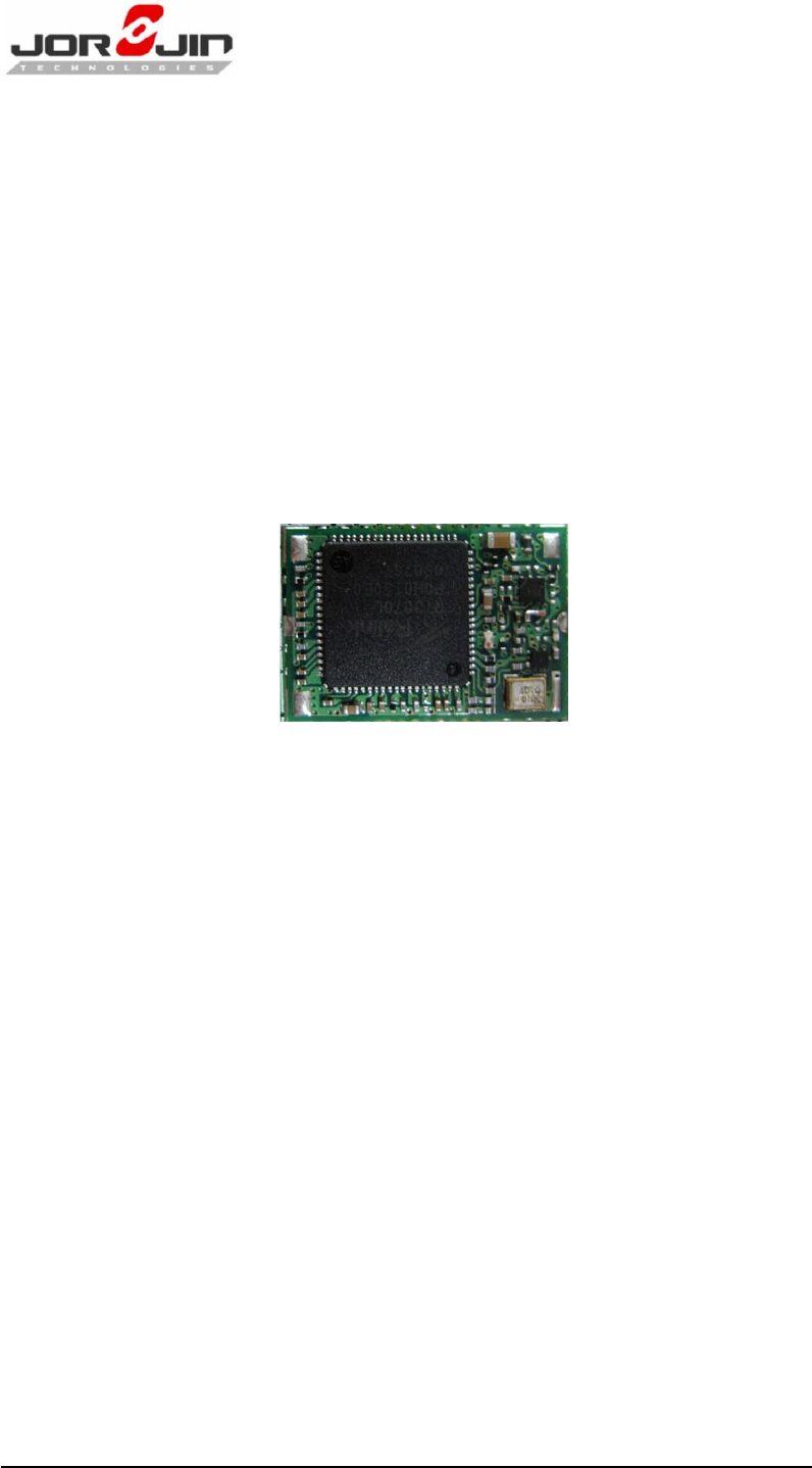
WN8020-00 is high performance and cost effective 802.11b/g/n WLAN USB
module. WN8020-00 is embedded with Ralink RT3070 a highly integrated
MAC/BBP and 2.4GHz RF single chip with 150Mbps PHY rate supporting.
It fully complies with IEEE 802.11n draft 3.0 and IEEE 802.11b/g feature
rich wireless connectivity at high standards, cost-effective, throughput
from extended distance. Optimized RF architecture and baseband
algorithms provide superb performance and low power consumption.
WN8020 is designed to support standard based features in the areas of
security, quality of service and international regulation, giving end users
the greatest performance anytime in any circumstance.
Feature
Host Interface USB2.0
1T1R with up to 150Mbps PHY Data Rate for Both TX and RX
LGA 38 pin package, including 4 ground pads.
Dimension 11.6±0.2(W) x 16.9±0.2 (L) x 1.4(H) mm without shielding
case
20MHz/ 40MHz Bandwidth Support
Legacy and High Throughput Modes
Support Antenna Diversity
Support Bluetooth Coexistence 2-wire Scheme
Support Turn ON/OFF WLAN System Module Function for Saving
Power Consumption

Doc No: WN8020-00-SPC-R06
Copyright © JORJIN TECHNOLOGIES INC. LIMITED 2010
CONFIDENTIAL
Page 4
Support LED Control Function (Active and Transmit Function)
With Smaller Size Suitable for Compact System Integration
Low Power Consumption, Extend the Battery Life
WEP 64/128, WPA, WPA2, TKIP, AES
QoS --- WMM, WMM-PS
WPS-PIN, PBC
Multiple BSSID Support
Cisco CCX Support
Operating Systems Support: Windows XP 32/64, Linux and
Macintosh
Low Cost
RoHS Compliant
Applications
Netbook/ Notebook
Printer
Digital Photo Frame/ Camera
Personal Navigation Device
Doc No: WN8020-00-SPC-R06
Copyright © JORJIN TECHNOLOGIES INC. LIMITED 2010
CONFIDENTIAL
Page 5
2. ELECTRICAL CHARACTERISTICS
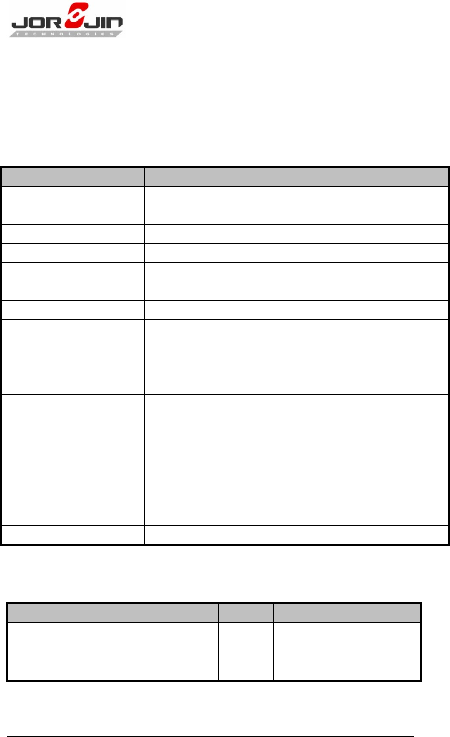
2.1. RF Characteristics
(Condition: VCC= 3.3V @ +25°C)
Feature
Description
Standards
Fully Compliant with IEEE 802.11 b/g/n Standard
Frequency Band
2400MHz ~ 2500MHz
Frequency Stability
< ±5ppm @Room Temperature +25°C
Modulation
OFDM and CCK
P HY D at a Rat e
Up to 150Mbps
Channel Bandwidth
20MHz and 40MHz
OFDM Output Power
15dBm (Typ.) @EVM<3%, all channel
CCK Spectral Mask
@Pout=18dBm
-37dBc (Typ.) @ 11~22MHz
-60dBc (Typ.) @ 22~33MHz
2f Harmonics
-55dBm (Typ.)
LO Leakage Peak Power
-64dBm (Typ.) @Transmit State
Receive Sensitivity
-65dBm (Typ.) @HT40M, MCS7
-71dBm (Typ.) @54M OFDM
-85dBm (Typ.) @11M CCK
-90dBm (Typ.) @1M CCK
RF Port Impedance
50Ω±10%
USB Differential Port
Impedance
90Ω±10%
Dimension
16.7(L) x 11.4(W) x 1.4(H) mm w/o Shielding Cover
2.2. Absolute Maximum Ratings
Parameter Name
Min.
Typ.
Max.
Unit
Operating Temperature
-10
85
°C
Supply Voltage Range: USB VCC
4.5
5.0
5.5
V
Storage Temperature Range
-55
150
°C
Doc No: WN8020-00-SPC-R06
Copyright © JORJIN TECHNOLOGIES INC. LIMITED 2010
CONFIDENTIAL
Page 6
3. SMT & BAKING RECOMMENDATION
3.1. Baking Recommendation
Baking condition:
- Follow MSL Level 4 to do baking process.
- After bag is opened, devices that will be subjected to reflow
solder or other high temperature process must be
a) Mounted within 72 hours of factory conditions <30°C/60% RH,
or
b) Stored at <10% RH.
- Devices require bake, before mounting, if Humidity Indicator
Card reads >10%
If baking is required, Devices may be baked for 8 hrs at 125 °C.
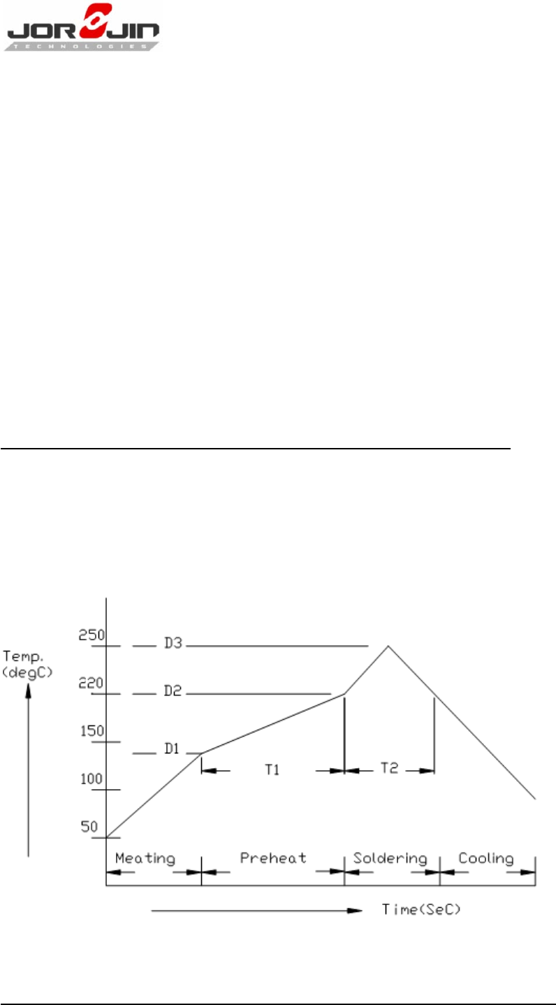
3.2. SMT Recommendation
Recommended Reflow profile:
Doc No: WN8020-00-SPC-R06
Copyright © JORJIN TECHNOLOGIES INC. LIMITED 2010
CONFIDENTIAL
Page 7
No.
Item
Temperature (°C)
Time (sec)
1
Pre-heat
D1: 140 ~ D2: 200
T1: 80 ~ 120
2
S ol d er i ng
D2: = 220
T2: 60 +/- 10
3
Peak-Temp.
D3: 250 °C max
Note: (1) Reflow soldering is recommended two times maximum.
(2) Add Nitrogen while Reflow process: SMT solder ability will be
better.
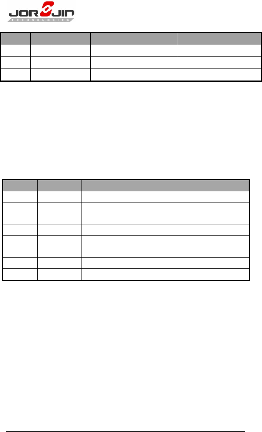
8. History Change
Revision
Date
Description
R 0.1
2009/04/08
Revisi on 0.1
R 0.2
2009/08/25
Add Feature list – package information, RoHS
Compliant; Update Baking & SMT Recommendation
R 0.3
2009/08/28
Add Mechanical Side View on Page 8
R 0.4
2009/09/02
Modify Mechanical Characteristic, Add Layout
Footprint Recommendation
R 0.5
2009/09/16
Modify Mechanical Characteristic
R 0.6
2010/01.05
Correct P9 GND Pin Assignment
This equipment has been tested and fo und to comply with the limits for
a Clas s B d igital de vice, pursuant to P art 15 of the FCC Rules. These
limits are designed to prov ide reas onable protecti on against harmful
interference i n a resi dential i nstallation. T his equi pment generates ,
uses and can rad iate radio frequency energy and, if not installed and
used i n accordance wi th the instructions, ma y c ause h armful
interference to r adio communi cations. Howev er, there i s no
guarantee that interference will not occur in a particular installation. If
this equi pment does cause harmful in terference to rad io or telev ision
reception, which can be determined by turning the equipment off and
on, the user is encouraged to try to correct the i nterference by one of
the following measures:
Reorient or relocate the receiving antenna.
Increase the separation between the equipment and receiver.
Connect the equi pment i nto an outl et on a ci rcuit different from
that to which the receiver is connected.
Consult the dealer or an experienced radio/TV technician for help.
This device complies with Part 15 of the FCC Rules. Operation is subject
to the follow ing two condi tions: (1) This device may not cause harmful
interference, and (2 ) th is dev ice must accept any i nterference
received, including interference that may cause undesired operation.
This device and its antenna must not be co-located or operating in conjunction with
any other
antenna or transmitter.
This module is intended for OEM integrator. The OEM integrator is still responsible for the
FCC compliance requirement of the end product, which integrates this module. 20cm
minimum distance has to be able to be maintained between the antenna and the
users for the host this module is integrated into. Under such configuration, the FCC
radiation exposure limits set forth for an population/uncontrolled environment can be
satisfied.
Any changes or modifications not expressly approved by the manufacturer could void
the user's authority to operate this equipment.
USERS MANUAL OF THE END PRODUCT:
In the user manual of the end product, the end user has to be informed to keep at
least 20cm separation with the antenna while this end product is installed and
operated. The end user has to be informed that the FCC radio-frequency exposure
guidelines for an uncontrolled environment can be satisfied. The end user has to also
be informed that any changes or modifications not expressly approved by the
manufacturer could void the user's authority to operate this equipment.
If the size of the end product is smaller than 8x10cm, then additional FCC part 15.19
statement is required to be available in the user manual: This device complies with
Part 15 of FCC rules. Operation is subject to the following two conditions: (1) this
device may not cause harmful interference and (2) this device must accept any
interference received, including interference that may cause undesired operation.
LABEL OF THE END PRODUCT:
The final end product must be labeled in a visible area with the following " Contains TX
FCC ID: PWQ-00EFR370000 ". If the size of the end product is larger than 8x10cm, then
the following FCC part 15.19 statement has to also be available on the label: This
device complies with Part 15 of FCC rules. Operation is subject to the following two
conditions: (1) this device may not cause harmful interference and (2) this device must
accept any interference received, including interference that may cause undesired
operation.