GEOVISION RU9003 UHF RFID Reader User Manual Chapter 1 Introduction
GEOVISION INC. UHF RFID Reader Chapter 1 Introduction
Users Manual

1
GV-RU9003 UHF RFID Reader
Introduction
GV-RU9003 is a Radio Frequency Identification (RFID) reader of ISO18000-6C (EPC GEN2)
standard. Designed for parking lot management, the reader can read RFID tag within 10 m
(32.8 ft).
Features
Built-in antenna and RF module
Effective identification with specially designed antenna pattern
Compatible with access controller using Wiegand 64 interface
Ideal sensing range within 10 m (32.8 ft)
Special energy-saving design reducing power consumption
Support for external sensors and controllers
Electronic tag compliant with EPC Gen II (ISO18000-6C) standard
R&D patent for EMI reduction
NCC/FCC/CE certification
Notice
1. The product pattern is certified by the FCC. Unauthorized modification of the frequency,
power, or originally designed functions and characteristics of the RFID reader are
prohibited.
2. This product has a water-resistant design. Unauthorized removal of the screws and case
of the product will damage the water-resistant performance and void product warranty.
3. Cables are water-resistant. Do not damage the shield, as it will also damage water-
resistant performance.
4. The reader should be positioned so that personnel in the area for prolonged periods may
safely remain at least 20 cm (8 in) in an uncontrolled environment from the reader’s
surface.
5. Avoid the interference of other radio frequencies with the look-up table frequency-
hopping spread spectrum (FHSS).
2
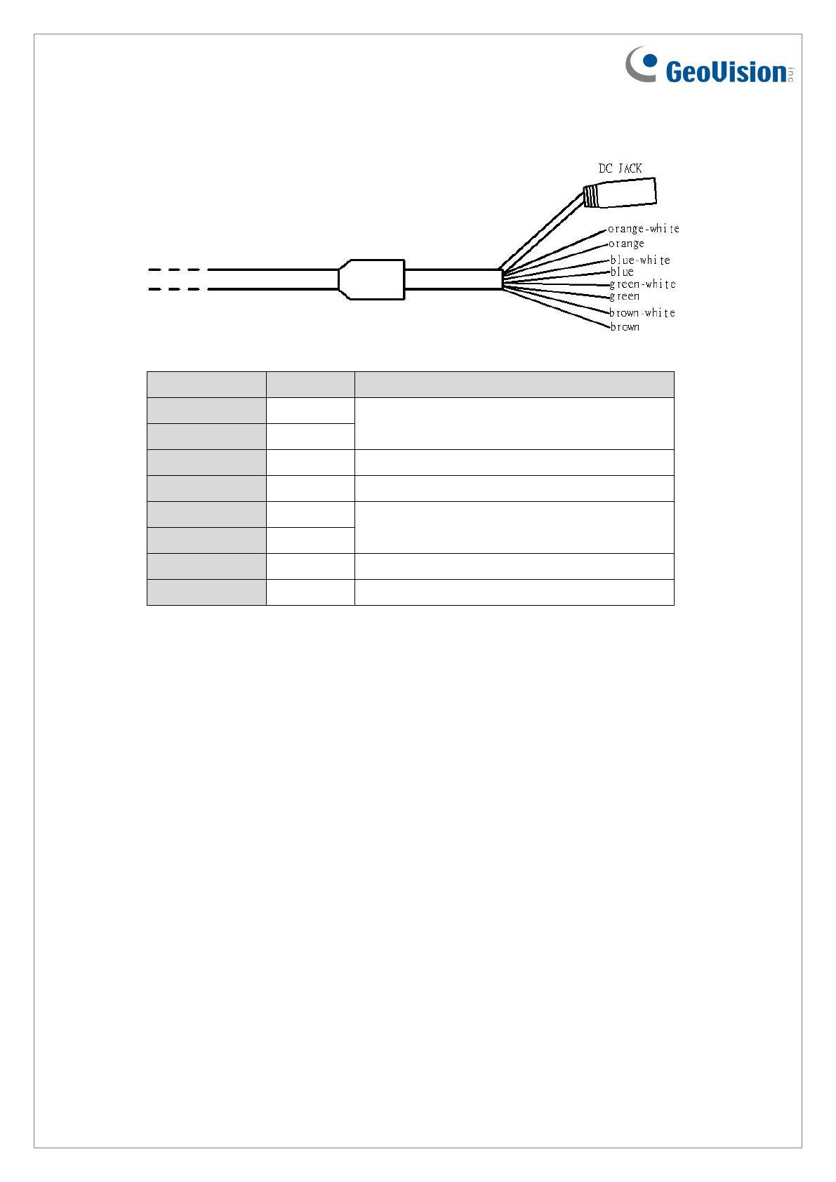
Output Cable Descriptions
Wire Color Definition Function
Orange-White D485+
Not functional
Orange D485-
Blue-White GND GND
Blue GND GND
Green-White DATA 1
Wiegand communication interface
Green DATA 0
Brown-White DI External control signal input, H:3.3V / L:0V
Brown DO Not functional
1. Wiegand Communication Interface
1.1. Connect with access controller using Wiegand interface (one-way operation).
1.2. Support by Wiegand 64 interface.
2. DI (external control signal input)
2.1. Signal level defining: High level (H) : 3.3V / Low level (L) : 0V (GND signal)
2.2. When the external control signal input is at high level and the GV-RU9003 is in the
standby mode, the GV-RU9003 will not output any identification code to the back-
end access controller.
2.3. When the external control signal input is at low level and the GV-RU9003 is in the
working mode, the GV-RU9003 will output the identification code on the tag to the
back-end access controller.
2.4. If DI is not in use, connect it with the blue or blue-white wire.
3
Recommended Installation of GV-RU9003 RFID Reader
1. Secure the GV-RU9003 RFID reader on a column, pedestal, wall, or beam at a height
between 1.8 - 2.2 m (5.9 – 7.2 ft) above the ground. Be sure to leave some space to
adjust the reader’s angle to the upper, lower, left, or right position.
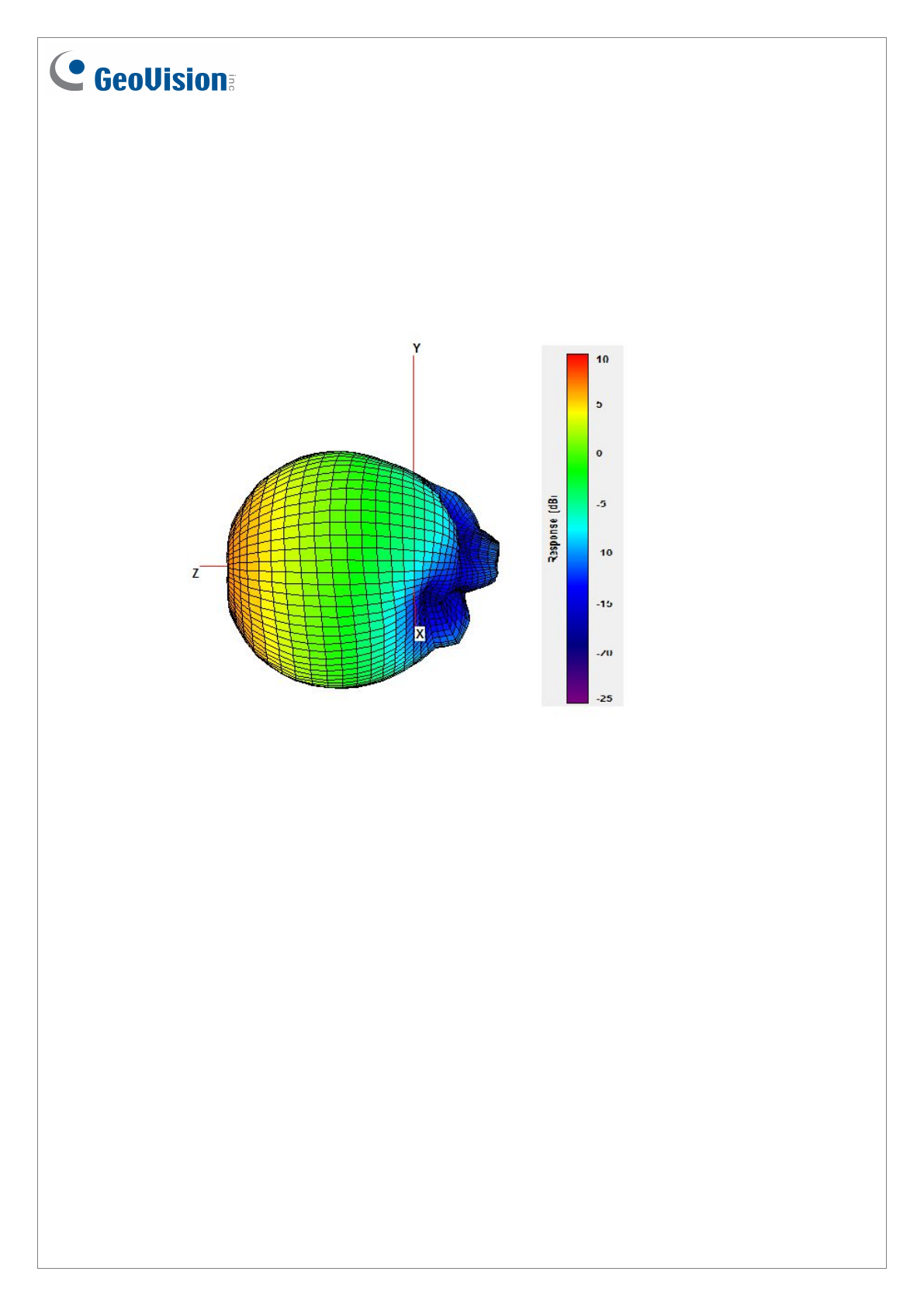
2. Check the antenna pattern as listed below and make sure that the tags on the passing
vehicles will be on the opposite side of the reader.
3. Although the ideal sensing range of GV-RU9003 is within 10 m (32.8 ft), the actual
sensing range varies due to weather (raining, fog, sunny) and installation method
(horizontal, inclining).
4
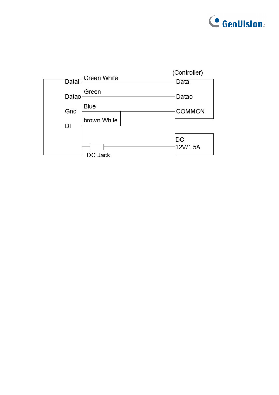
Connection of GV-RU9003 RFID Reader
1. Connect the GV-RU9003 to a Wiegand signal source based on the communication
interface of the access controller.
2. DI (brown-white) is the input signal (e.g. ground induction loop or photo interrupter)
controlling the operating mode of the GV-RU9003 with external control. If external
control is not in use, please connect it with the blue or blue/white wire.
5
Installing GV-RU9003
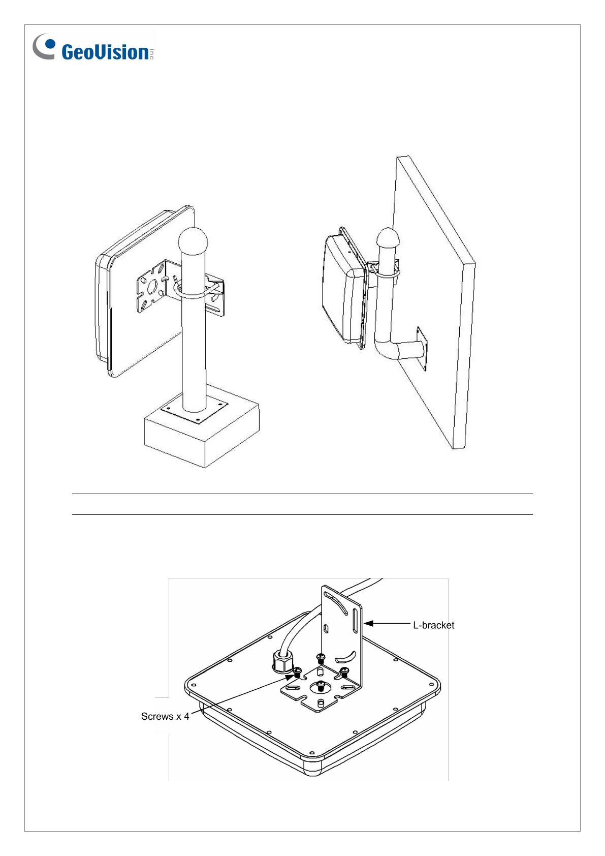
You can install the reader on a pole or a pillar. Two types of pole mounts are recommended,
as indicated below.
Note: Make sure the diameter of the pole is within 53 mm (0.17 ft).
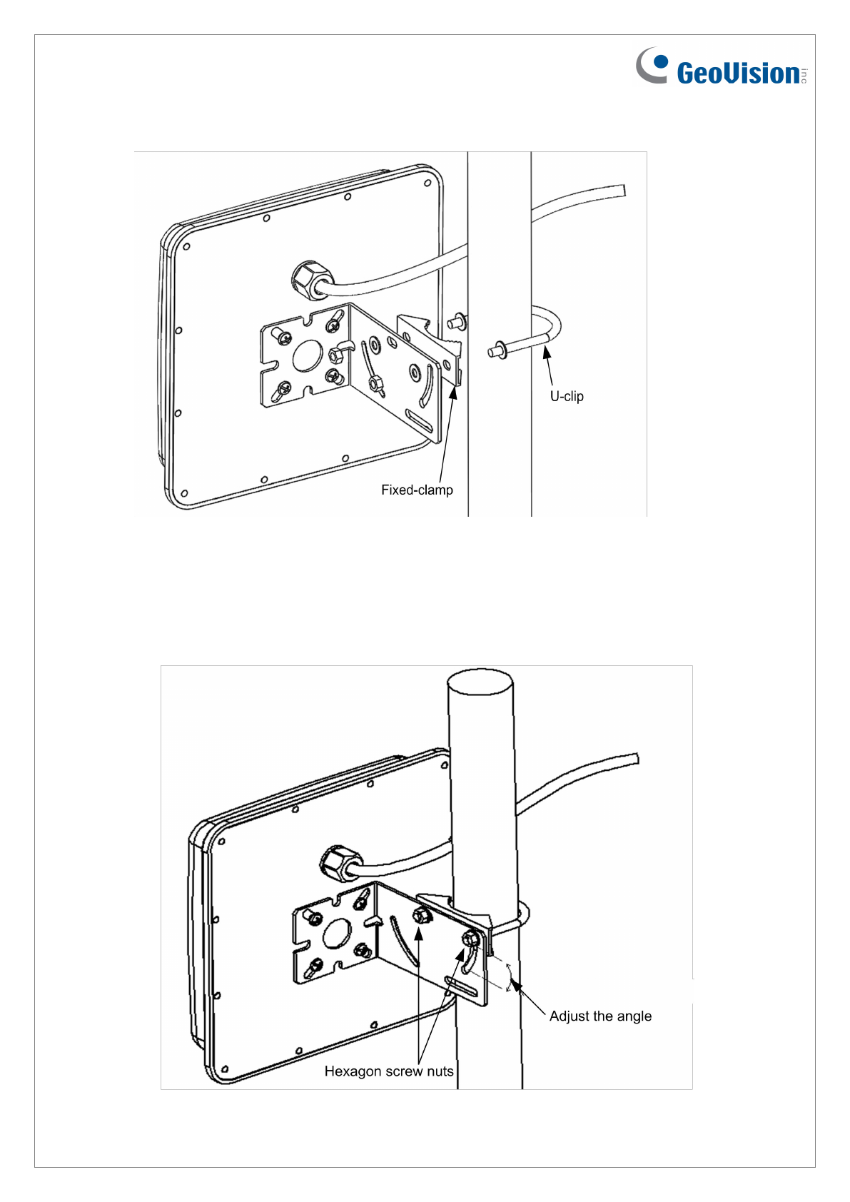
1. Secure the L-bracket with four screws (supplied) on the rear side of the UHF RFID
Reader.
6
2. Secure the reader on a pillar or a pole using fixed-clamp and U-clip.
3. Adjust the angle of the U-clip on L-bracket and secure the hexagon screw nuts.
7
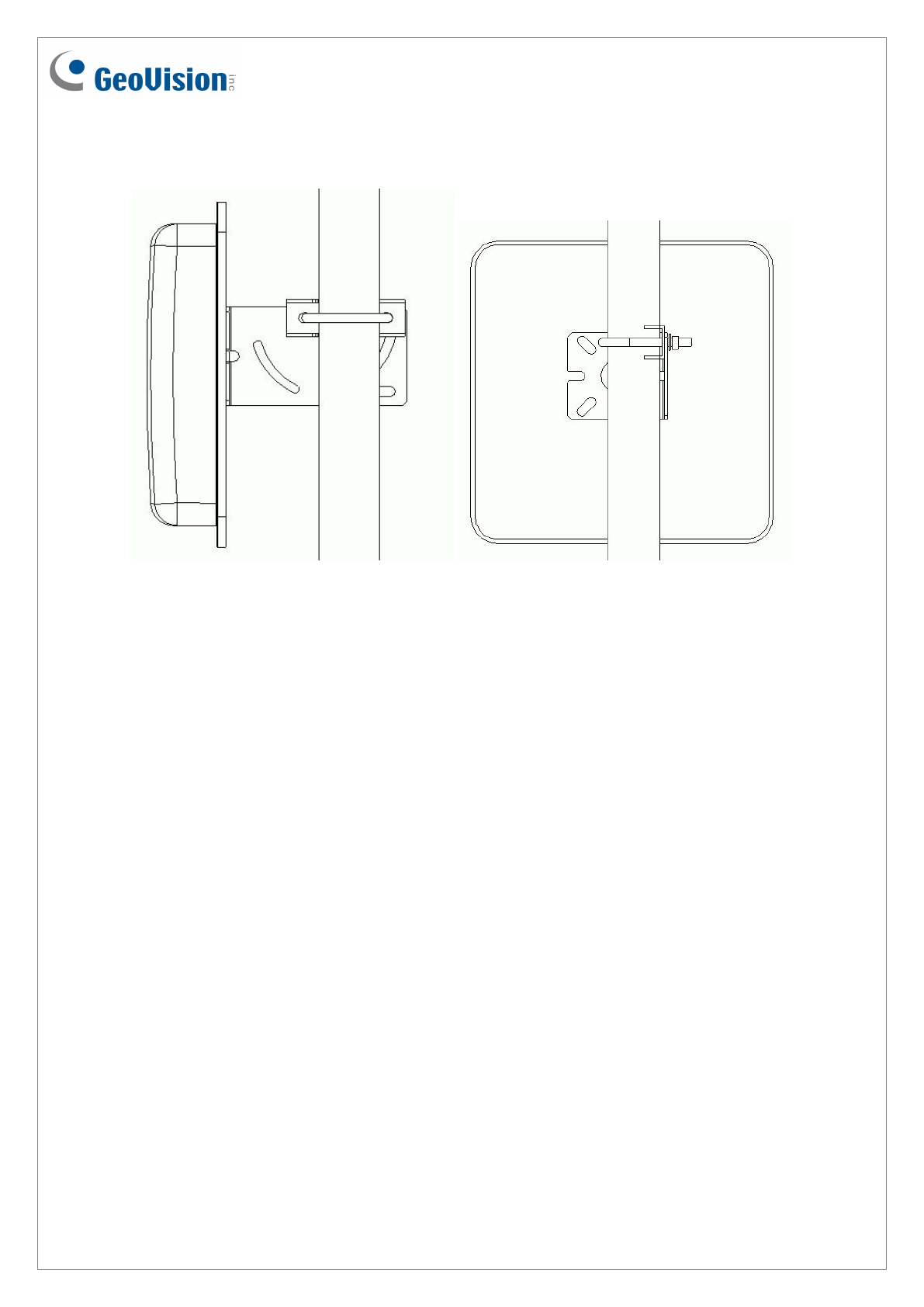
4. Overview of pole mount.
8
Specification
GV-RU9003
Input voltage 9 ~15 V
Antenna gain 7.71 dBi (circular polarization)
Antenna receiving 50 ohm U.FL.
Wiegand interface Wiegand 64 bit
Operating frequency RU9003 TW 922-928 MHz
RU9003 US 902-928 MHz
RU9003 EU 865-868 MHz
Emission power 27.9 dBm
Modulation scheme PR-ASK, ASK
Current <1A max.
Protocol EPC Gen2 (ISO 18000-6C)
Receiving sensitivity -85 dBm
Sensing range 10 m (32.8 ft) max.
Water resistance IP56
Operating temperature -20°C ~ 55 °C / -7.6°F ~ 131°F
Storage temperature -20°C ~ 85°C / -7.6°F ~ 185°F
LEDs Red, Green
Humidity 5-90 %
Dimensions 228 x 228 x 52.3 mm / 8.97 x 8.97 x 2.04 in
Weight 530 g / 1.16 lb
Certification NCC, FCC, CE
Note:
1. The GV-ASManager V4.4.2.0 is required.
2. Wiegand interface supports both GeoVision AS2xxx/4xxx/8xxx controllers and 3rd party
controllers (Wiegand 64 Bits).
3. Specifications are subject to change without notice.
9
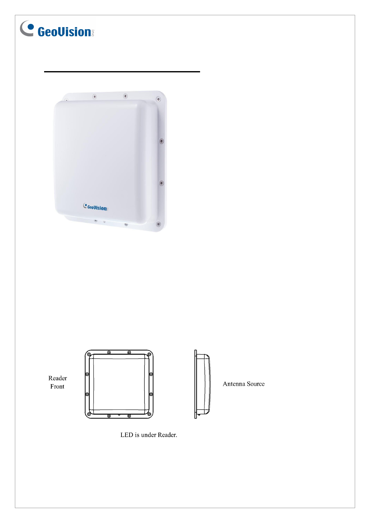
GV-RU9003 UHF RFID Reader
Overview
10
Packing List
1. GV-RU9003
2. L-Bracket
3. Fixed-clamp
4. U-clip
5. Screws x 4
6. Installation Guide
7. Warranty Card
Note: If any of these items is found missing or damaged, please contact your local supplier for
replacement.
Installing GV-RU9003
Note: For the diagrams listed below, the LED indicator locates at the lower part of UHF
RFID Reader.
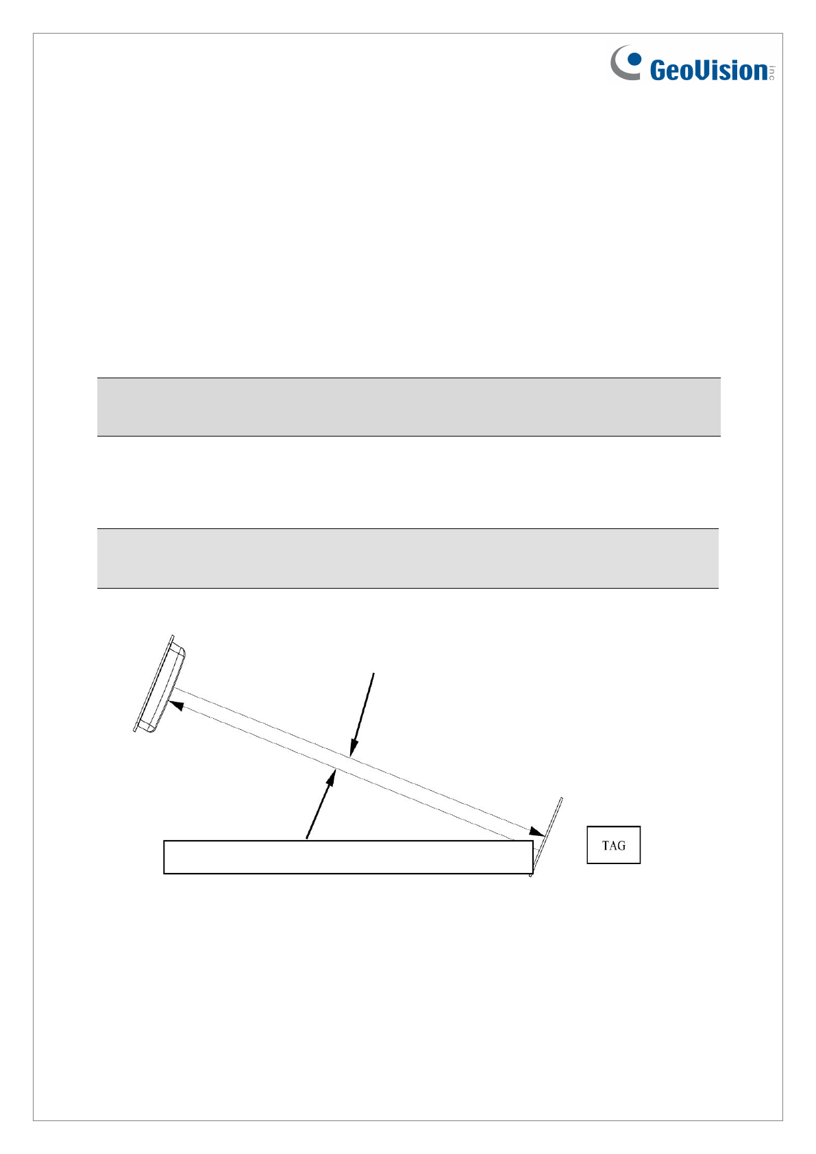
1. Install the RFID reader with the antenna paralleled to the Tag for better reading results.
The Tag receives signals and returns them to the Reader.
11
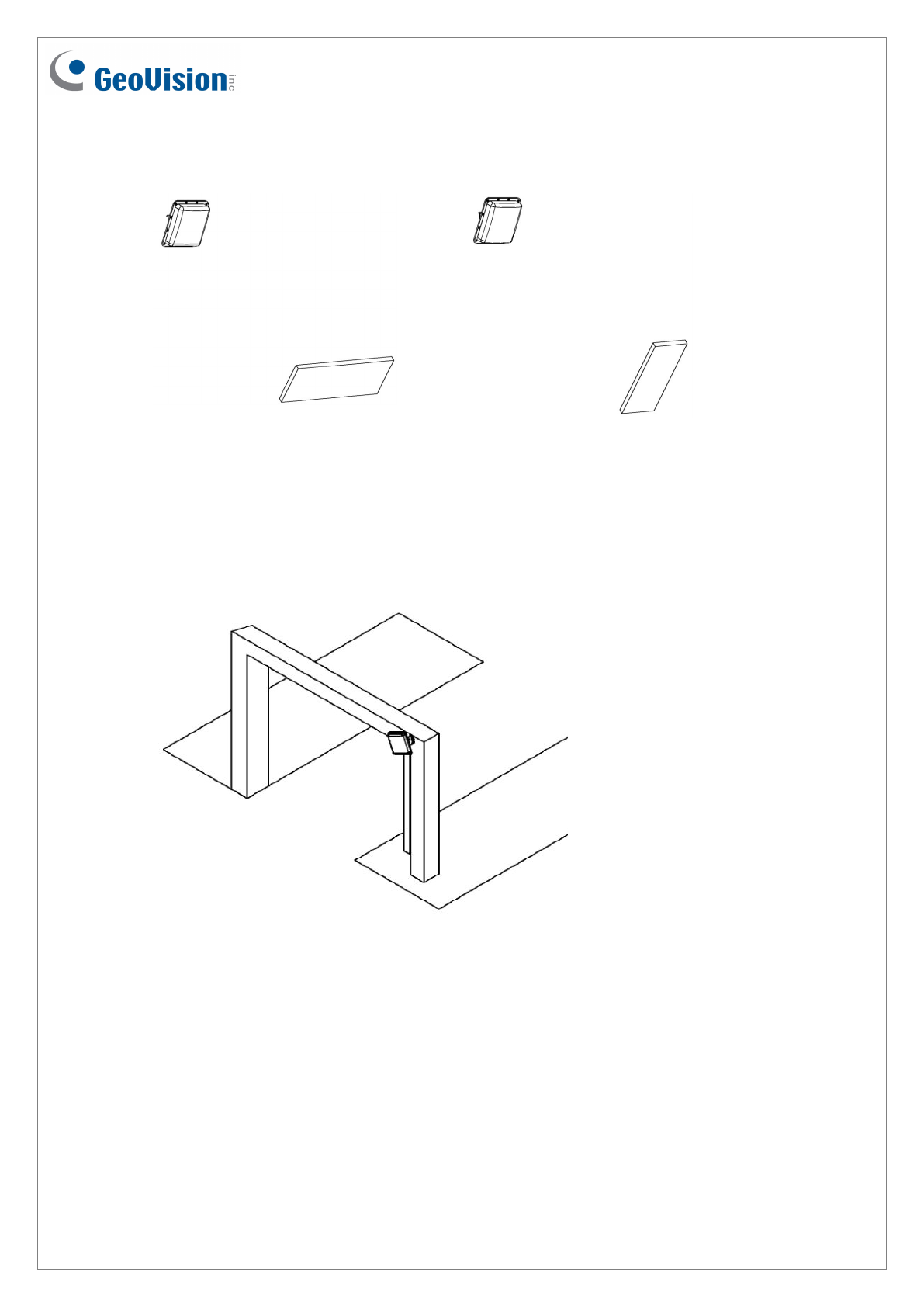
2. Install the RFID Reader and the Tag as shown below.
Correct Misplaced
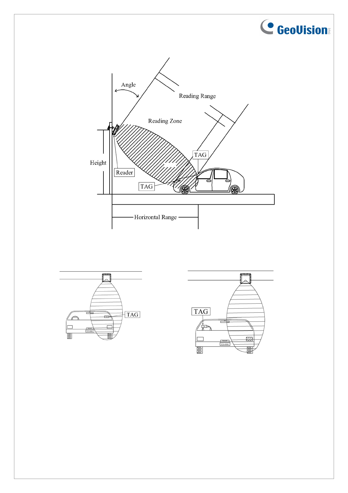
3. RFID Reader installation position
3.1 Do not install RFID Reader near mental or the metallic substance will affect the
electromagnetic field type.
3.2 Recommended height to set RFID reader is 1.8 ~ 2.2 m (5.9 ~ 7.2 ft). The height
should not be lower than the location of RFID Tag.
3.3 Recommended angle to set RFID reader is 15-20 degree. Adjust the angle
according to the actual installation site.
3.4 Keep any barrier away from the reading zone between RFID Reader and the Tag.
12
4. The RFID Reader must be installed at same side of the Tag or at the nearest reading
range to the Tag.
4.1 Upper Installation
Proper Improper
13
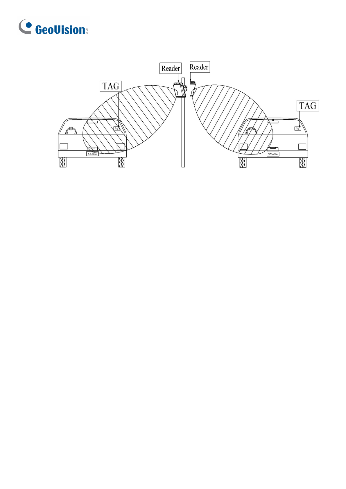
4.2 Side Installation
Proper Improper
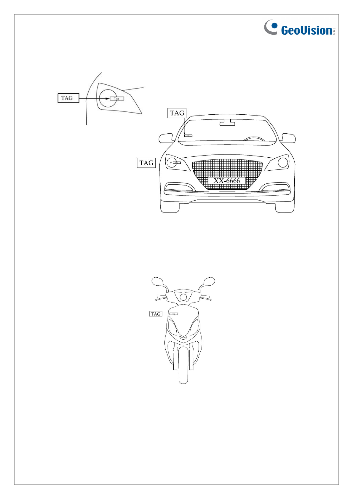
5. Recommended Tag Position
Vehicles
5.1 Place the tag on the front windshield or headlight, at the nearest reading range to the
reader.
5.2 When placing the Tag on the headlight, keep the Tag away from the metal body of
the vehicle.
5.3 If the car windshield glass contains metallic line, it will affect the reading range.
To avoid such situation, install the Tag on the headlight.
14
5.4 Windshield insulation films that contain metal ingredients will affect the reading
range. To avoid such situation, install the Tag on the headlight.
Motorcycles
5.5 Install the Tag on the front shield and at the closest range to the RFID Reader.
5.6 If there is no front shield available, it is suggested to install the Tag on the plastic
body of motorcycle at the closest range to the RFID Reader.
15
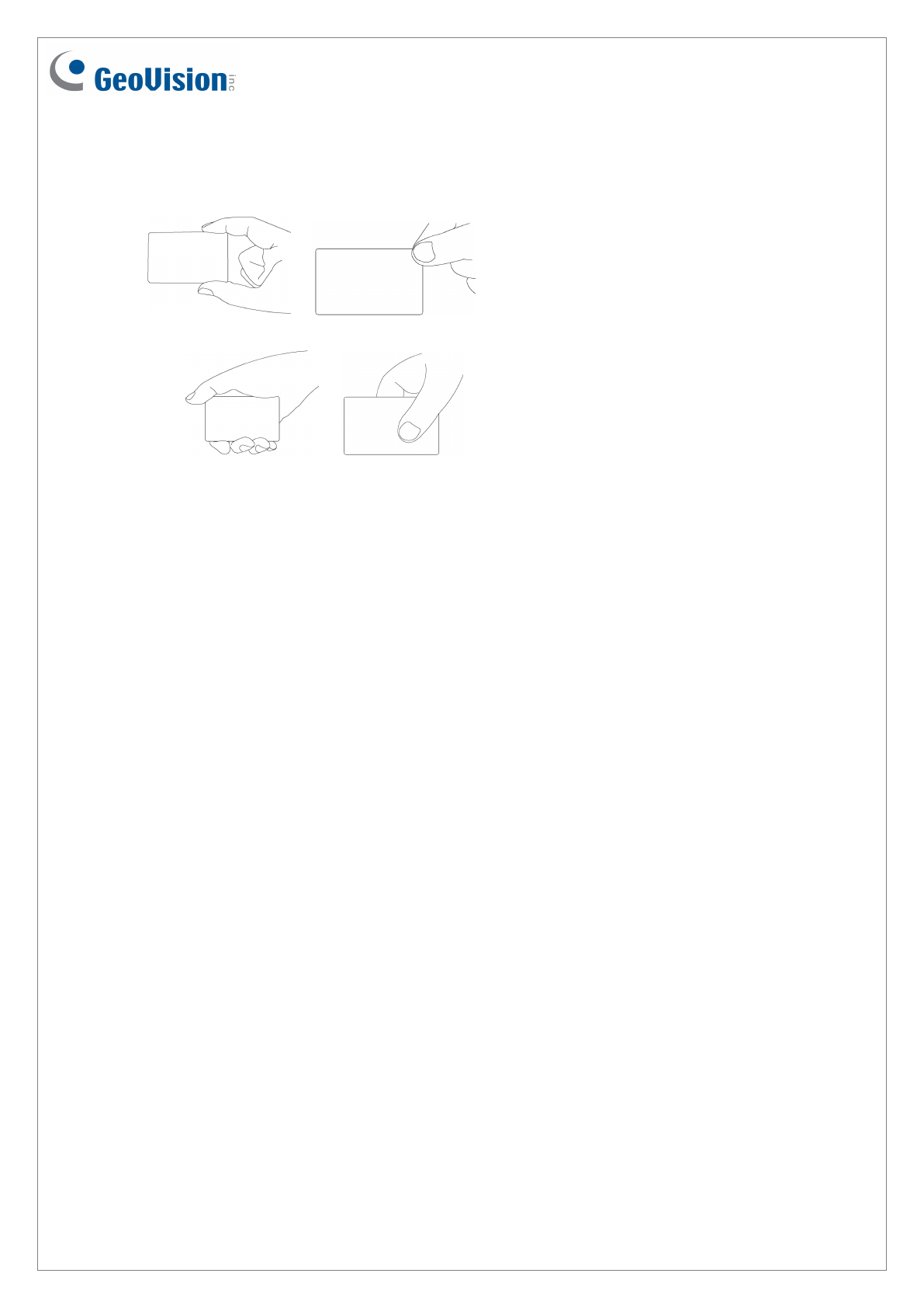
6. For card-type tags, hold the card as shown below to ensure reading results.
Correct
Misplaced
7. Notice
11.1 When the installation is complete, examine and adjust the environment parameters
again for better reading results.
11.2 Reading range between RFID Reader and the Tag will be shorten on rainy days.
11.3 When two or more RFID Readers are installed together, co-channel interference
might occur. To avoid interference, place the readers away from each other at a
distance 5 times the effective reading range or set the readers to separate frequency
channels.
11.4 When using the power supply, check if there is an interference problem. If yes, use
the filter to attenuate the power supply noise.

16
Federal Communications Commission (FCC) Statement
15.21
You are cautioned that changes or modifications not expressly approved by the part
responsible for compliance could void the user’s authority to operate the equipment.
15.105(b)
This equipment has been tested and found to comply with the limits for a Class B digital
device, pursuant to part 15 of the FCC rules. These limits are designed to provide
reasonable protection against harmful interference in a residential installation. This
equipment generates, uses and can radiate radio frequency energy and, if not installed and
used in accordance with the instructions, may cause harmful interference to radio
communications. However, there is no guarantee that interference will not occur in a
particular installation. If this equipment does cause harmful interference to radio or television
reception, which can be determined by turning the equipment off and on, the user is
encouraged to try to correct the interference by one or more of the following measures:
-Reorient or relocate the receiving antenna.
-Increase the separation between the equipment and receiver.
-Connect the equipment into an outlet on a circuit different from that to which the receiver is
connected.
-Consult the dealer or an experienced radio/TV technician for help.
This device complies with Part 15 of the FCC Rules. Operation is subject to the
following two conditions:
1) this device may not cause harmful interference and
2) this device must accept any interference received, including interference that may cause
undesired operation of the device.
RF exposure:
To comply with the FCC RF exposure compliance requirements, this device and its antenna
must not be co-located or operating in conjunction with any other antenna or transmitter.
FCC RF Radiation Exposure Statement:
1. This Transmitter must not be co-located or operating in conjunction with any other antenna or
transmitter.
2. This equipment complies with FCC RF radiation exposure limits set forth for an uncontrolled
environment. This equipment should be installed and operated with a minimum distance of 20
centimeters between the radiator and your body.