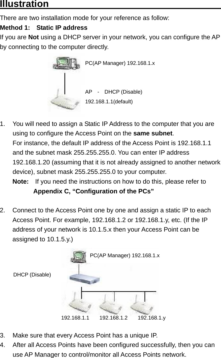
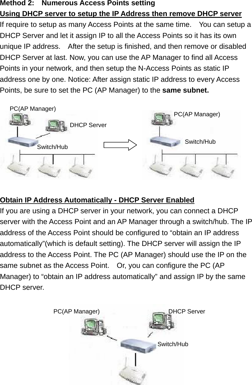
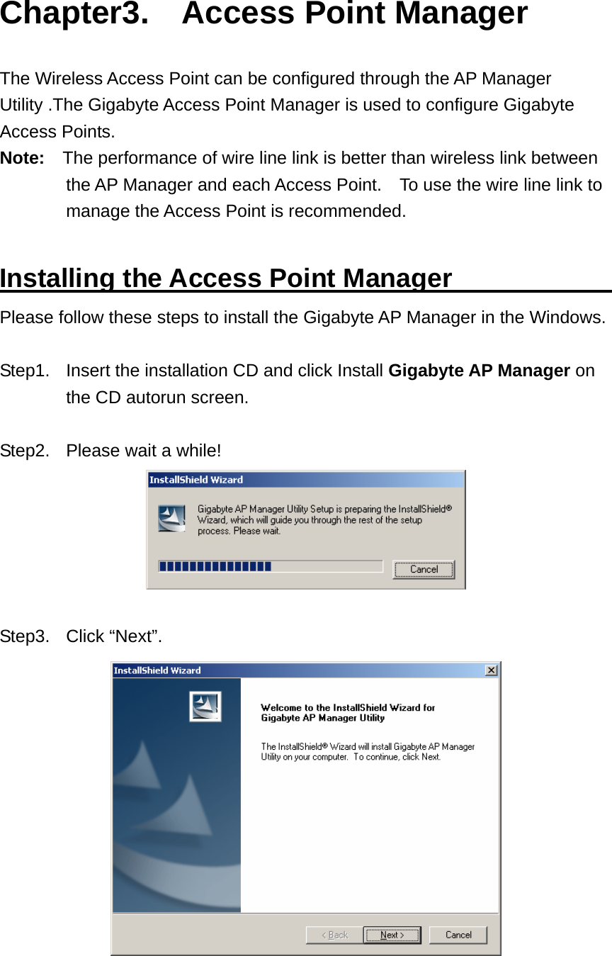
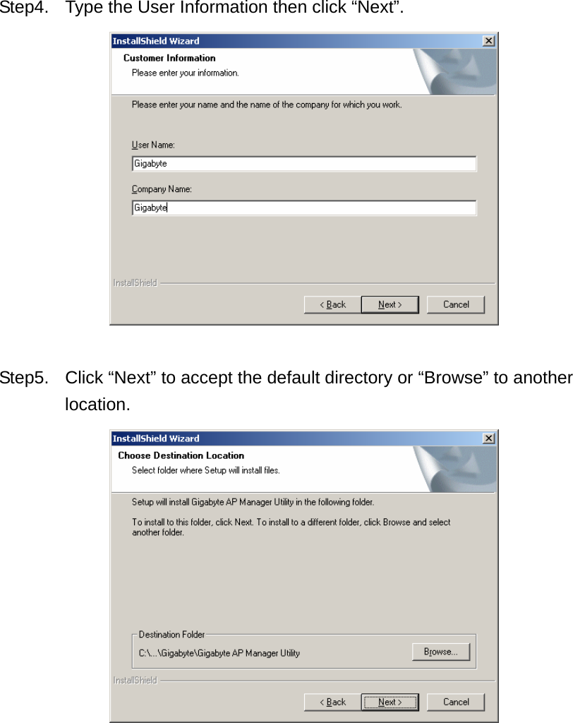
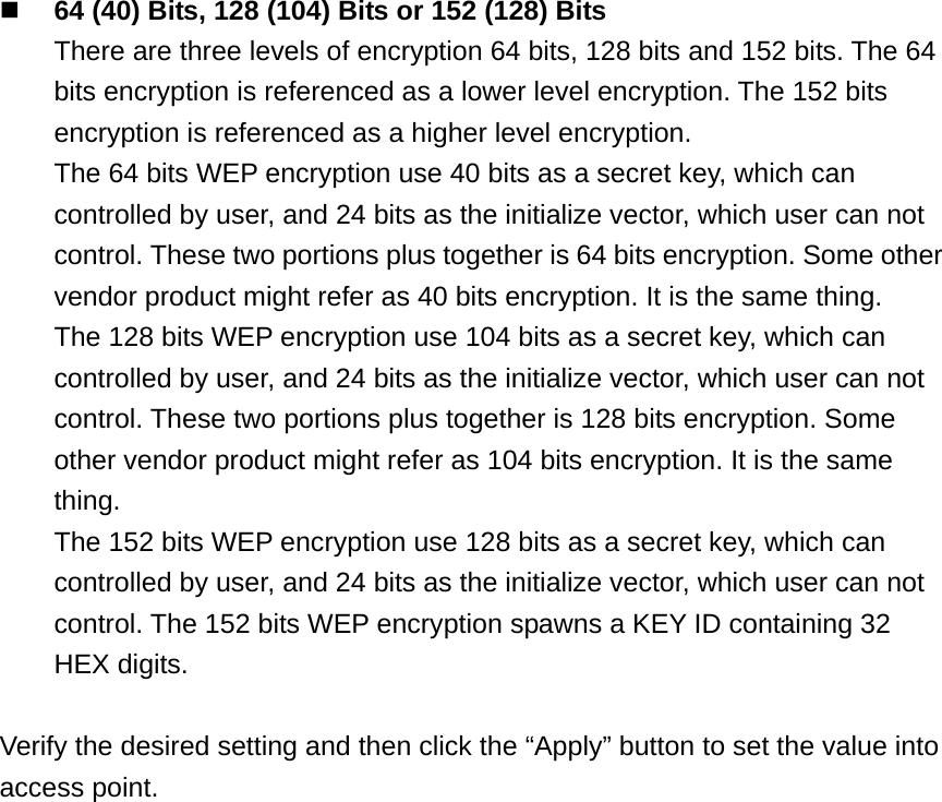
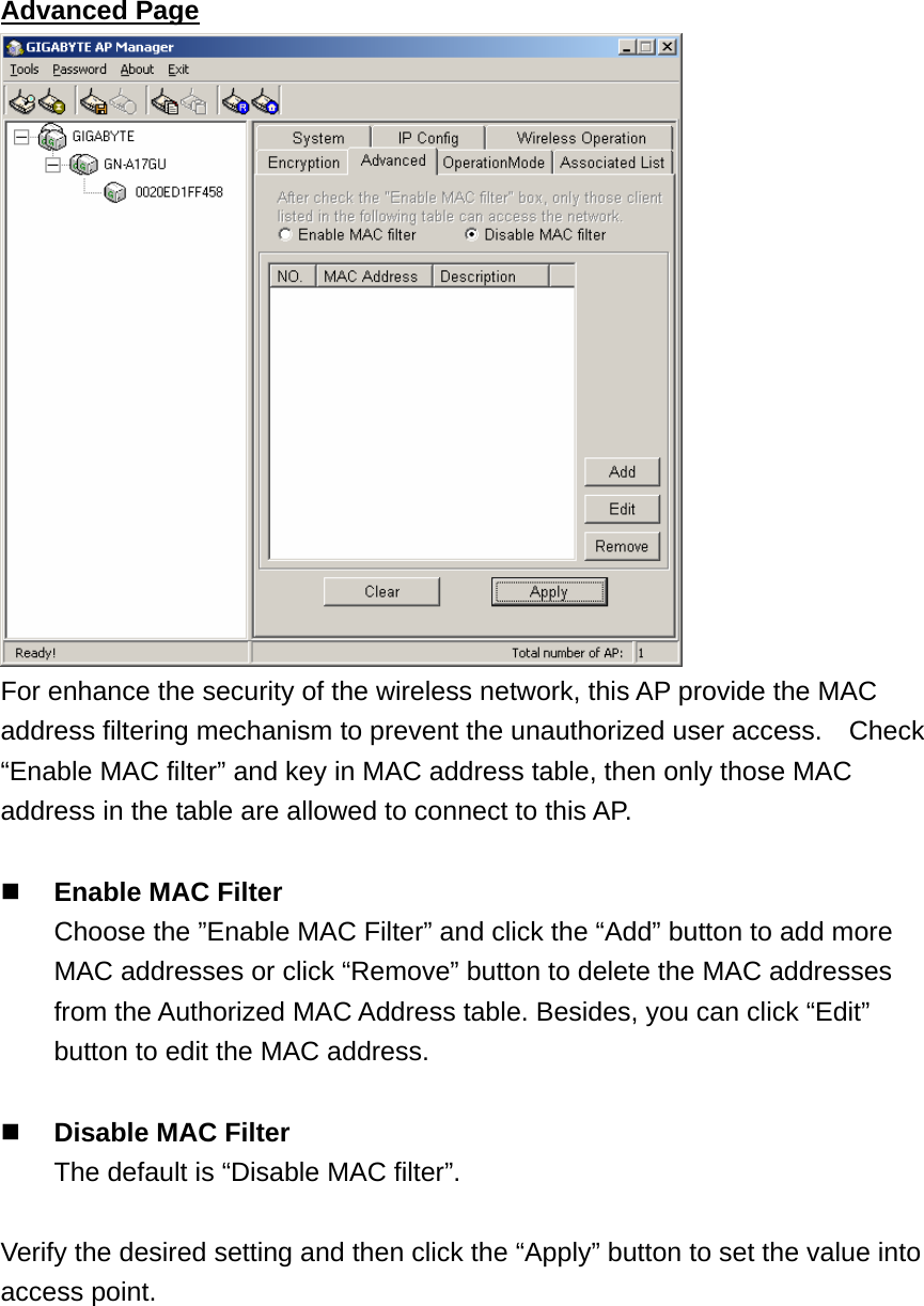
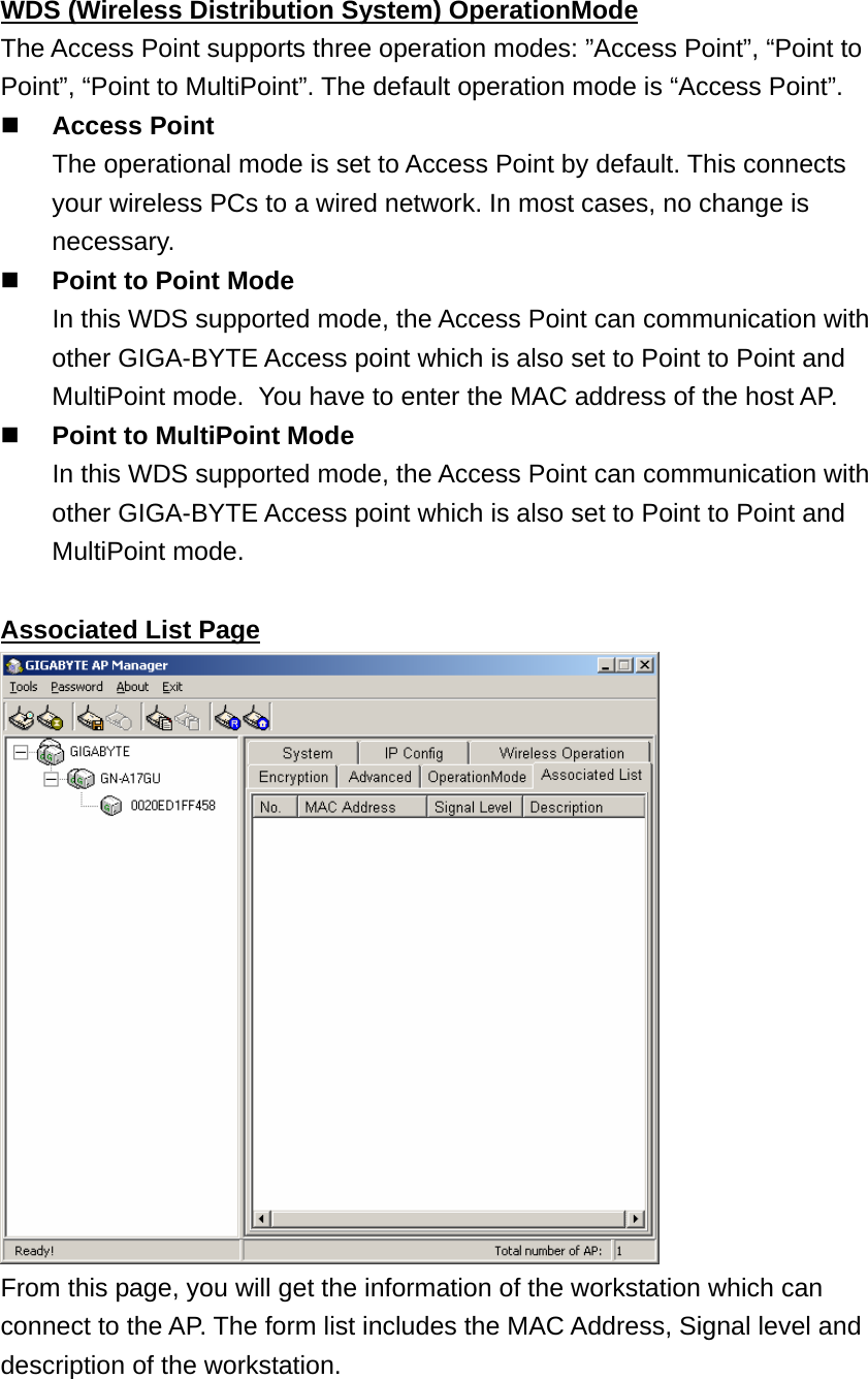
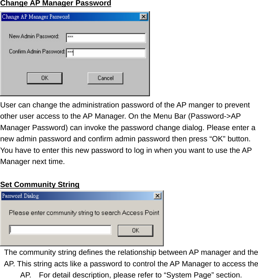
GIGA BYTE TECHNOLOGY GN-BR02G Wireless Broadband Router / Wireless Access Point User Manual

GIGA-BYTE TECHNOLOGY CO., LTD. Wireless Broadband Router / Wireless Access Point

Contents

Users Manual 1

GN-AP02G  Wireless Access Point       User’s Manual             www.gigabyte.com.tw
Federal Communication Commission Interference Statement This equipment has been tested and found to comply with the limits for a Class B digital device, pursuant to Part 15 of the FCC Rules. These limits are designed to provide reasonable protection against harmful interference in a residential installation. This equipment generates, uses and can radiate radio frequency energy and, if not installed and used in accordance with the instructions, may cause harmful interference to radio communications. However, there is no guarantee that interference will not occur in a particular installation. If this equipment does cause harmful interference to radio or television reception, which can be determined by turning the equipment off and on, the user is encouraged to try to correct the interference by one of the following measures: -    Reorient or relocate the receiving antenna. -    Increase the separation between the equipment and receiver. -    Connect the equipment into an outlet on a circuit different from that to which the       receiver is connected. -    Consult the dealer or an experienced radio/TV technician for help.  FCC Caution: To assure continued compliance, any changes or modifications not expressly approved by the party responsible for compliance could void the user    authority to operate this equipment.  This device complies with Part 15 of the FCC Rules. Operation is subject to the following two conditions: (1) This device may not cause harmful interference, and (2) this device must accept any interference received, including interference that may cause undesired operation.   IMPORTANT NOTE: FCC Radiation Exposure Statement: This equipment complies with FCC radiation exposure limits set forth for an uncontrolled environment. This equipment should be installed and operated with minimum distance 20cm between the radiator & your body. This transmitter must not be co-located or operating in conjunction with any other antenna or transmitter.
Contents Chapter1  Introduction  ....................................................…………............4 Overview  .........................................................................…………4 Features   ........................................................................…………4 Package Contents    ..........................................................………….5 The Rear Panel        ..............................................................………..5 The Front Panel    ...............................................................………...6 Chapter 2  Installation  .................................................................………...7 Hardware Requirements    ...................................................……….7 System Requirements   ......................................................………7 Internet Configuration Requirements   ...............................………7 Hardware Installation    ..........................................................……...8 Connect to Access Point .......................................................……...8 Illustration    .........................................................................……..9 Chapter3.  Access Point Manager   ..................................…..........…….11 Installing the Access Point Manager....................................……..11 Using the Access Point Manager  ………………….............…….15 Appendix A: Specification    ……..................................……………......……33
Chapter1  Introduction  Overview                                      Thank you for using Gigabyte GN-AP02G Wireless-G Access Point. The IEEE 802.11g standard is designed as a higher-bandwidth - 54M bit/sec - successor to the popular 802.11b, or Wi-Fi standard, which tops out at 11M bit/sec. An 802.11g access point will support 802.11b and 802.11g clients.  The GN-AP02G Wireless-G Access Point lets you connect IEEE 802.11g or IEEE802.11b        devices to the network. With its high-speed data transmissions of up to 54 Mbps, you complete a lot of work in a short amount of time. Network users can share a broadband Internet connection, access e-mail, download large files, videoconference, and distribute and play digital images, videos, and MP3 files.      And with up to 152-bit WEP encryption, you can feel relieved that your wireless network communications are private. Easy to set up and use, the GN-AP02G provide you an AP Manager Configuration utility.   Features                                      ♦  IEEE 802.11b/g compliant and compatible with Wi-Fi ♦  One option of plug in wireless card for Upgrade ♦  Friendly SNMP Management Support ♦  Advanced Wireless Security support -  Support 802.1x Secure Wireless Access -  Support 64/128/152-bit WEP encryption -  Support Access Control List (ACL) ♦ Extended Distributed Wireless Systems (EDWS) support -  Wireless Distribution System (WDS) support (Point to Multi-Point and Point to Point) -  Simultaneous operation of AP and WDS functions ♦  Built-In DHCP server for Assigning IP Address ♦  Transmits data rate up to the maximum speed of 54Mbps for IEEE 802.11g
♦  Dynamically scales the data rate to 54, 48, 36, 24, 18, 12, 9, and 6Mbps for IEEE 802.11g  Package Contents                             Before the installation procedures, please ensure the components are not damaged during the shipping. The shipment of the GN-AP02G includes:  -  One GN-AP02G Wireless-G Access Point -  One AC Power Adapter -  One Installation CD with the AP Manager and User Guide Soft Copy - One User Guide -  One RJ-45 Cable - One Cradle -  One wall mounting kit  Please contact your local distributor or authorized reseller immediately for any missing or damaged components. If you require returning the damaged product, you must pack it in the original packing material or the warranty will be voided.  The Rear Panel                                 The Access Point’s ports are located on the Access Point’s rear panel.  Power       The power port is where you connect the power adapter.  One Ethernet LAN Port     RJ-45, Auto-sensing for 10/100M Ethernet LAN    connection    Init Bottom   Initial reset (Init to factory default) and Hardware reset.  Wireless antenna   One 2.4 GHz antenna
The Front Panel                                LEDs The Access Point’s LEDs display information about the Access Point’s status.   Power (Green Light)   When the Green light is on, the power is supplied to the router.  Note:    When you are applying the changes to save the configuration, the Power LED will be off for a while.  LAN (Green Light) On  The link active at 10/100Mbps. Flicker  Data is being transmitted/received.   WLAN (Green Light) On  The wireless function is acting. Flicker  Data is being transmitted/received.  External PCMCIA Card slot Support the Gigabyte GN-WMAG and the GN-WLMA101 Wireless PCMCIA Card, but the GN-WLMA101 Wireless PCMCIA Card is recommended.  Note:  Please expand the Wireless Lan card when power off.
Chapter 2    Installation  Hardware Requirements                        To use the Wireless Access Point on your network, each computer may need the following requirements:   An installed 802.11b/g wireless adapter.   An Ethernet LAN switch or hub.   A wired RJ-45 Ethernet cable  System Requirements                            A Computer with Windows, Macintosh, or Linux-based operating system.   To run AP Manager, you need a computer with Windows operating system.  Internet Configuration Requirements            In order to connect your Access Point to the AP Manager, you will need the following configuration parameters to configure the TCP/IP setting of your computer:    Static IP Address: 192.168.1. x (e.g, 2 ~ 253)   Subnet mask: 255.255.255.0   Default Gateway: 192.168.1.254
Hardware Installation                           Follow these steps to install the Wireless Access Point.  1.  Choose a proper place for Access Point. In general, the best location is at the center of your wireless coverage area, within line of sight to all wireless devices. Keeping clear of metal obstructions and away from direct sunlight. 2.  Place the Access Point in the desired location. Normally, the higher you place the antenna, the better the performance will be. The antenna   position enhances the receiving sensitivity. 3.  Attach one end of an RJ-45 Ethernet cable to the Access Point and attach the other   end to a network hub, switch, router, or patch panel (possibly on a wall). 4.  Attach one end of the AC power adapter to the Access Point and the other end to a power outlet. (Note: Only use the power adapter supplied by Gigabyte in the product package. Using a different adapter may result in product damage.)  For the average home, signal range should not be an issue. If you experience low or no signal strength in areas of your home that you wish to access, consider positioning the Access Point in a location directly between the computers with wireless adapters. Additional Access Points can be connected to provide better coverage in rooms where the signal does not appear as strong as desired.  Connect to Access Point                        Wired Ethernet Cable You can connect a LAN cable from your computer Network card to the Access Point without using a Network switch or hub.  Wireless Connection If you are using the wireless connection, you can connect to the Access Point using the Gigabyte Access Point Manager without a wired Ethernet cable.
Illustration                                     There are two installation mode for your reference as follow: Method 1:    Static IP address If you are Not using a DHCP server in your network, you can configure the AP by connecting to the computer directly.  1.  You will need to assign a Static IP Address to the computer that you are using to configure the Access Point on the same subnet.  For instance, the default IP address of the Access Point is 192.168.1.1 and the subnet mask 255.255.255.0. You can enter IP address 192.168.1.20 (assuming that it is not already assigned to another network device), subnet mask 255.255.255.0 to your computer. Note:    If you need the instructions on how to do this, please refer to Appendix C, “Configuration of the PCs”  2.  Connect to the Access Point one by one and assign a static IP to each Access Point. For example, 192.168.1.2 or 192.168.1.y, etc. (If the IP address of your network is 10.1.5.x then your Access Point can be assigned to 10.1.5.y.)   3.  Make sure that every Access Point has a unique IP. 4.  After all Access Points have been configured successfully, then you can use AP Manager to control/monitor all Access Points network. PC(AP Manager) 192.168.1.x AP  -  DHCP (Disable)192.168.1.1(default) DHCP (Disable) PC(AP Manager) 192.168.1.x 192.168.1.1 192.168.1.2 192.168.1.y
Method 2:    Numerous Access Points setting Using DHCP server to setup the IP Address then remove DHCP server If require to setup as many Access Points at the same time.    You can setup a DHCP Server and let it assign IP to all the Access Points so it has its own unique IP address.    After the setup is finished, and then remove or disabled DHCP Server at last. Now, you can use the AP Manager to find all Access Points in your network, and then setup the N-Access Points as static IP address one by one. Notice: After assign static IP address to every Access Points, be sure to set the PC (AP Manager) to the same subnet.                 Obtain IP Address Automatically - DHCP Server Enabled If you are using a DHCP server in your network, you can connect a DHCP server with the Access Point and an AP Manager through a switch/hub. The IP address of the Access Point should be configured to “obtain an IP address automatically”(which is default setting). The DHCP server will assign the IP address to the Access Point. The PC (AP Manager) should use the IP on the same subnet as the Access Point.    Or, you can configure the PC (AP Manager) to “obtain an IP address automatically” and assign IP by the same DHCP server.   PC(AP Manager) DHCP Server Switch/Hub PC(AP Manager) Switch/Hub PC(AP Manager)  DHCP Server Switch/Hub
Chapter3.  Access Point Manager  The Wireless Access Point can be configured through the AP Manager Utility .The Gigabyte Access Point Manager is used to configure Gigabyte Access Points. Note:    The performance of wire line link is better than wireless link between the AP Manager and each Access Point.    To use the wire line link to manage the Access Point is recommended.  Installing the Access Point Manager             Please follow these steps to install the Gigabyte AP Manager in the Windows.  Step1.  Insert the installation CD and click Install Gigabyte AP Manager on the CD autorun screen.  Step2.  Please wait a while!   Step3. Click “Next”.
Step4.  Type the User Information then click “Next”.   Step5.  Click “Next” to accept the default directory or “Browse” to another location.
Step6. Click “Next”.   Step7. Click “Next”.
Step8.  Please wait a while.   Step9.  Click ”Finish” to complete setup.
Using the Access Point Manager                You can launch Gigabyte AP Manager through Start \ Programs \ Gigabyte AP Manager Utility \ Gigabyte AP Manager.  Enter the default password “admin” and click “OK” button.   It will automatically search for Access Points on the same subnet when you open the Gigabyte AP Manager. You may click the icon          to searching for Access Points manually.
 Tree structure   ESSID (GIGABYTE)      AP Name (GN-AP02G)                           MAC Address (0020ED001700)   Menu bar  Tools  Allow you to “search” for AP by ESSID, AP Name, MAC Address, and IP Address and “Connect to AP by IP” And allow you to         “Save”, “Load” the AP configuration and “Copy”, “Paste” the configuration at the current page. Besides, it includes both ”System Reboot” and “Load” Default?  Password  Allow you to change the AP Manager password and set the SNMP community string.  About    An online help and the AP Manager version.  Exit   Exit the AP Manager.   Note:      When you search for AP by AP Name (Tools->Search->By AP Name). You can press the “Search next” to continue to search the same name of AP.
 Tool bar     Find Access Point     Find all AP in the same subnet.   Save AP Configuration     Save all setting of the AP to a temp file.   Load AP Configuration   Load the setting of the temp file that you saved before to the current AP.   Page Copy     Copy the setting of the current page.   Page Paste   Paste the setting you has copied to the current page.(You can paste the setting of AP1 to AP2 at the same tab page.)   System Reboot     Reboot the Access Point.   Load Default     Set the Access Point to the manufacture default.    Connect to AP by IP   If you want to manage the AP in the different subnet, use this function and key in the IP.
System Page The System Page displays the Device Information and the Change Community String function.   Device Information   The Device Information include the AP name, MAC address, device description, the version information, the wireless type and card config type.  1.  You can change the AP Name to whatever unique name, which can   represent this AP. 2.  Based on the “Card Config Type” you can choose which wireless type   you want to use.    Note:      1)  Please expand the Wireless Lan card when power off. 2)  The embedded “Card1” support the IEEE802.11b/g/turbo-g/super-g standards and the external “Card2” can support more standards. Recommending not to choose the Wireless-G type at the same time, or it will be affect the performance of the Access Point.        3.  The “Card Config Type” allows you to select which wireless card you   want to configure.
 Change Community String   This function can let you change the community string to the AP. You can change a new community string on purpose to prohibit other AP Manager access and manage your AP. After you change the community string to AP, you need to do two following actions.    1.  Use Password->Set Community String on the Menu Bar to set the   community string to the AP manager. The AP Manager and the AP should have the same community string. Otherwise the AP Manager will not be able to find the AP with different community string.  2.  Please memorize the community string or write it down at   somewhere.      In case you forget the community string, you have to press the AP init button and then the AP setting (include community string) will be restore to default value.  Note:    The SNMP community string defines the relationship between an SNMP manager system (AP Manager) and the agent systems (all APs). This string acts like a password to control the AP Manager to access the AP.    The default value of the community string is “public” You can change the community string of AP Manager by using Password->Set Community String on the Menu Bar. Initbottom
IP Config Page  The IP Configure tab allows you to configure the IP parameters of the access point.  IP Address     Use this option to assign an IP address to the access point. The   default IP address is 192.168.1.1.    Please make sure the assigned   IP address is unique on your network.  Subnet Mask     Specify the subnet mask of the access point. The default subnet mask is  255.255.255.0.  Gateway     Enter the IP address of the default route. The default gateway is       192.168.1.254.  After you change the IP address of the AP, please also change the PC (AP Manager) IP address to the same subnet. And then click the “Find Access Point” icon; AP manager will search the AP on the network.   DHCP Mode There are four settings under this option you can choose: ”Disabled”, “Client Enabled”, “Server Enabled” and “Auto”.    Disabled is the default setting.
  If you want to get IP address from the DHCP server automatically on your   network, you will select “Client Enabled”. Or you want to use the Access Point as a DHCP server to automatically assign dynamic IP address on the network, you will select “Server Enabled”.   DHCP Client Range & DNS   If you select the “Server Enabled” setting, please input the IP address   range and the DNS for your network. The DNS information provied by your ISP company.   802.1d Spanning Tree   Enabled or Disabled the 802.1d Spanning Tree function. The default setting is Disabled.  Verify the desired setting and then click the “Apply” button to set the value into access point.
Wireless Operation Page  Normally, you can have the wireless works smoothly even you didn’t change any item in this page.  Region Because of the different region has a different open channel regulation, please check whether the default region value is your local area. If it did not appear properly region please contact your local distributor or authorized reseller immediately.  Channel ID   Please choose the channel, which you can get best performance. Normally, it doesn’t need to change.  Preamble Type   The preamble field shall be provided so that the receiver can perform the necessary operations for synchronization. Under this option two setting are possible: “Long” or ”Short”. The default value is “Long”.  Transmit Rate You can select one of the rates among 6M, 9M, 12M, 18M, 24M, 36M, 48M and 54M based on your need. The default value is “54M”. If the “Auto Rate” option is enable, it will not be able to perform the “Transmit Rate” function. Note: The Data Rate of the 802.11b standard are 11M, 5.5M, 2M, 1M.     The Data Rate of the 802.11g turbo and 802.11g super can up to 108Mbps.
 Auto Rate   In this item you can select either “Enable” or “Disable” The default value is    ”Enable”.  Enable  If the selection is “Enable”, the transfer rate will automatically change to the optimum rate allowed. The range of auto-change will base on the setting of “Transmit Rate”.      Transmit Rate setting:     54M : range is among 6M, 9M, 12M, 18M, 24M, 36M, 48M and 54M     48M : range is among 6M, 9M, 12M, 18M, 24M, 36M and 48M     36M : range is among 6M, 9M, 12M, 18M, 24M and 36M     24M : range is among 6M, 9M, 12M, 18M and 24M       18M : range is among 6M, 9M, 12M and 18M       12M : range is among 6M, 9M and 12M     9M : range is between 6M and 9M     6M  : no auto-change.    The transmit rate is fixed at 6M.   Disable  There is no transfer rate auto-change. The transfer rate will be defined by the “Transmit Rate” column.   Hidden ESSID   This setting allows you to hide the ESSID in wireless transmission. Those who don’t know the ESSID will not be able connect to the AP. The default value is “Disable”.   RTS Threshold   This value should remain at its default setting of 2347. Should you encounter inconsistent data flow, only minor modifications are recommended. The setting range is 0 ~ 2347.   ESSID   The ESSID or SSID is the name represent the AP in the wireless network. The ESSID of all AP in your network should set to identical for the mobile client can roam between access points. This ESSID string is case sensitive of up to 32 ASCII characters.  Verify the desired setting and then click the “Apply” button to set the value into access point.
Encryption Page  This page is the security configuration of the wireless connection.    Protects your information with the highest level of industry-standard WEP encryption: 64/128-bit for 802.11b standard, and up to 152-bit for 802.11g standards. When the “Disable” is selected there is no WEP encryption.    When “64bit”, “128bit” or “152bit” selected there is encrypted date transfer to prevent unauthorized user to access the wireless network.  Authentication Type   You may choose between “Open System”, “Shared Key”, “Both”, “802.1x -   Dynamic WEP”, “WPA” and “WPA-PSK”. The Authentication Type default           is set to “Open System”. Open System  in which the sender and the recipient do NOT share a secret key. Each party generates its own key-pair and asks the receiver to accept the randomly generated key. Once accepted, this key is used for a short time only. Then a new key is generated and agreed upon.  Shared Key    is both the sender and the recipient share a secret key.   If the “Shared Key” or “Both” option is selected, it will not be able to perform the option “Disable” of the WEP Type.
If the 802.1x -Dynamic WEP option is selected, the Radius/WPA page will appear as shown below.    RADIUS server IP      Please assign a IP address to the primary RADIUS   server(authentication server).  RADIUS Port        The setting range is 1~65536 and the default value   is 1812.  RADIUS sercet    This filed can key in up to 256 character.  RADIUS Re-Key      Under this option two setting are possible: "Enable”   or “Disable”. The default value is “Enable”.  Verify the desired setting and then click the “Apply” button to set the value into access point.   WPA  if you have been using Wi-Fi for a while, you are probably familiar with the 802.1X authentication protocol. This protocol allows users to authenticate into a wireless network by means of a RADIUS Server. In standard Wi-Fi, 802.1X authentication is optional. However, 802.1X authentication is a requirement for WPA. If your environment does not have a RADIUS server in place, you can still use WPA in spite of the 802.1X requirement. As an alternative to RADIUS, WPA supports the use of a preshared key.
  One of the biggest drawbacks to traditional WEP security is that changing the encryption key is optional. Even if you do switch encryption keys from time to time, there is no option for globally rekeying all access points and all wireless NICs.   Instead, rekeying is a tedious manual process and is completely impractical for large organizations. After all, the instant you rekey an access point, none of the clients will be able to access it until they are also rekeyed.   But with WPA, the rekeying of global encryption keys is required. In the case of unicast traffic, the encryption key is changed after every frame using Temporary Key Integrity Protocol (TKIP). This protocol allows key changes to occur on a frame by frame basis and to be automatically synchronized between the access point and the wireless client. Global rekeying works by advertising the new keys to   wireless clients.   The TKIP is really the heart and soul of WPA security. TKIP replaces WEP encryption. And although WEP is optional in standard Wi-Fi, TKIP is required in WPA. The TKIP encryption algorithm is stronger than the one used by WEP but works by using the same hardware-based calculation mechanisms WEP uses.   The TKIP protocol actually has several functions. First, it determines which encryption keys will be used and then verifies the client security configuration. Second, it is responsible for changing the unicast encryption key for each frame. Finally, TKIP sets a unique starting key for each authenticated client that is using a preshared key.   AES (Advanced Encryption Standard), A standard, sponsored by the National Institute of Standards and Technology, for protecting data through encryption. AES supports key sizes of 128 bits, 192 bits and 256 bits and will serve as a replacement for the Data Encryption Standard (DES), which has a key size of 56 bits. In addition to the increased security that comes with larger key sizes, AES can encrypt data much faster than Triple-DES, a DES enhancement that which essentially encrypts a message or document three times. WPA PSK  WPA use of a preshared key.
When WPA option is selected, the Radius/WPA page will appear as shown below.   WPA Algorithm      There are three settings you can select : “TKIP”,   “AES” and “Auto”.   RADIUS server IP      Please assign a IP address to the primary RADIUS   server(authentication server).  RADIUS Port        The setting range is 1~65536 and the default value   is 1812.  RADIUS sercet    This filed can key in up to 256 character.  WPA Re-Key              Under this option two setting are possible: "Enable”   or “Disable”. The default value is “Enable”.   WPA Re-Key Interval   Enter a Rekey Interval (normally the unit is   seconds).  Verify the desired setting and then click the “Apply” button to set the value into access point.
When WPA PSK option is selected, the Radius/WPA page will appear as shown below.   WPA Algorithm      There are three settings you can select : “TKIP”,   “AES” and “Auto”.   WPA shared Key    This filed can key in up to 256 character.  WPA-PSK Re-Key      Under this option two setting are possible: "Enable”   or “Disable”. The default value is “Enable”.   WPA PSK Interval    Enter a Rekey Interval (normally the unit is   seconds).  Verify the desired setting and then click the “Apply” button to set the value into access point.
 64 (40) Bits, 128 (104) Bits or 152 (128) Bits There are three levels of encryption 64 bits, 128 bits and 152 bits. The 64 bits encryption is referenced as a lower level encryption. The 152 bits encryption is referenced as a higher level encryption. The 64 bits WEP encryption use 40 bits as a secret key, which can controlled by user, and 24 bits as the initialize vector, which user can not control. These two portions plus together is 64 bits encryption. Some other vendor product might refer as 40 bits encryption. It is the same thing. The 128 bits WEP encryption use 104 bits as a secret key, which can controlled by user, and 24 bits as the initialize vector, which user can not control. These two portions plus together is 128 bits encryption. Some other vendor product might refer as 104 bits encryption. It is the same thing. The 152 bits WEP encryption use 128 bits as a secret key, which can controlled by user, and 24 bits as the initialize vector, which user can not control. The 152 bits WEP encryption spawns a KEY ID containing 32 HEX digits.  Verify the desired setting and then click the “Apply” button to set the value into access point.
Advanced Page  For enhance the security of the wireless network, this AP provide the MAC address filtering mechanism to prevent the unauthorized user access.    Check “Enable MAC filter” and key in MAC address table, then only those MAC address in the table are allowed to connect to this AP.   Enable MAC Filter   Choose the ”Enable MAC Filter” and click the “Add” button to add more MAC addresses or click “Remove” button to delete the MAC addresses from the Authorized MAC Address table. Besides, you can click “Edit” button to edit the MAC address.   Disable MAC Filter   The default is “Disable MAC filter”.  Verify the desired setting and then click the “Apply” button to set the value into access point.
WDS (Wireless Distribution System) OperationMode The Access Point supports three operation modes: ”Access Point”, “Point to Point”, “Point to MultiPoint”. The default operation mode is “Access Point”.  Access Point   The operational mode is set to Access Point by default. This connects your wireless PCs to a wired network. In most cases, no change is necessary.  Point to Point Mode   In this WDS supported mode, the Access Point can communication with other GIGA-BYTE Access point which is also set to Point to Point and MultiPoint mode.   You have to enter the MAC address of the host AP.  Point to MultiPoint Mode   In this WDS supported mode, the Access Point can communication with other GIGA-BYTE Access point which is also set to Point to Point and MultiPoint mode.  Associated List Page  From this page, you will get the information of the workstation which can connect to the AP. The form list includes the MAC Address, Signal level and description of the workstation.
Change AP Manager Password  User can change the administration password of the AP manger to prevent other user access to the AP Manager. On the Menu Bar (Password->AP Manager Password) can invoke the password change dialog. Please enter a new admin password and confirm admin password then press “OK” button. You have to enter this new password to log in when you want to use the AP Manager next time.  Set Community String  The community string defines the relationship between AP manager and the AP. This string acts like a password to control the AP Manager to access the AP.    For detail description, please refer to “System Page” section.
Appendix A: Specification Physical Interface                              The Wireless Access Point includes 1 RJ-45 Ethernet LAN ports, one init hole and one antenna. Item Feature  Description 1.  LAN Port x 1     RJ-45, Auto-sensing for 10/100M Ethernet LAN connection. 2.  Init Bottom             Initial reset 3.  Wireless              1 external antenna and 1 internal antenna support diversity.  Specification                                   System Specification  Date Rate             11/5.5/2/1 Mbps for IEEE 802.11b  54/ 48/36/ 24/ 18/ 12/ 9/6 Mbps for IEEE 802.11g LAN Interface       10/100 Mbps LAN port with Auto-negotiation function  Protocol support    TCP/IP, DHCP, UDP, ICMP, ARP, TFTP, SNMP  Operating Frequency  2.4000 ?2.4835 GHz (Subject to local regulation)  Operating Range      Indoor : Approx. 30M~100M (100ft.~300ft.)       Outdoor : Approx. 100M~300M (300ft.~900ft.)       The range may vary by different environment  LED indicators        Power, Status, Wireless, LAN  OS support      Win95/98/2000/ME/XP/NT 4.0, Linux, Unix, Mac  AP Manager    Win95/98/2000/ME/XP Physical Specification  Power supply          5V DC 2A  Temperature           Operating Temperature: 0 to 40       Storage Temperature: -20 to 65  Humidity             10% to 85% non-condensing  Dimension            178 mm x 132 mm x 43 mm  Weight                 Gross Weight 320 ±5g

Navigation menu