GIGA BYTE TECHNOLOGY GN-WBKG USB STICK Wireless LAN Adapter User Manual
GIGA-BYTE TECHNOLOGY CO., LTD. USB STICK Wireless LAN Adapter
UserManual.wiki
>
GIGA BYTE TECHNOLOGY
>
GN WBKG User Manual
User Manual
Navigation menu
Upload a User Manual
Namespaces
Wiki Guide
HTML
PDF
Info
Views
User Manual
Discussion / Help
Navigation
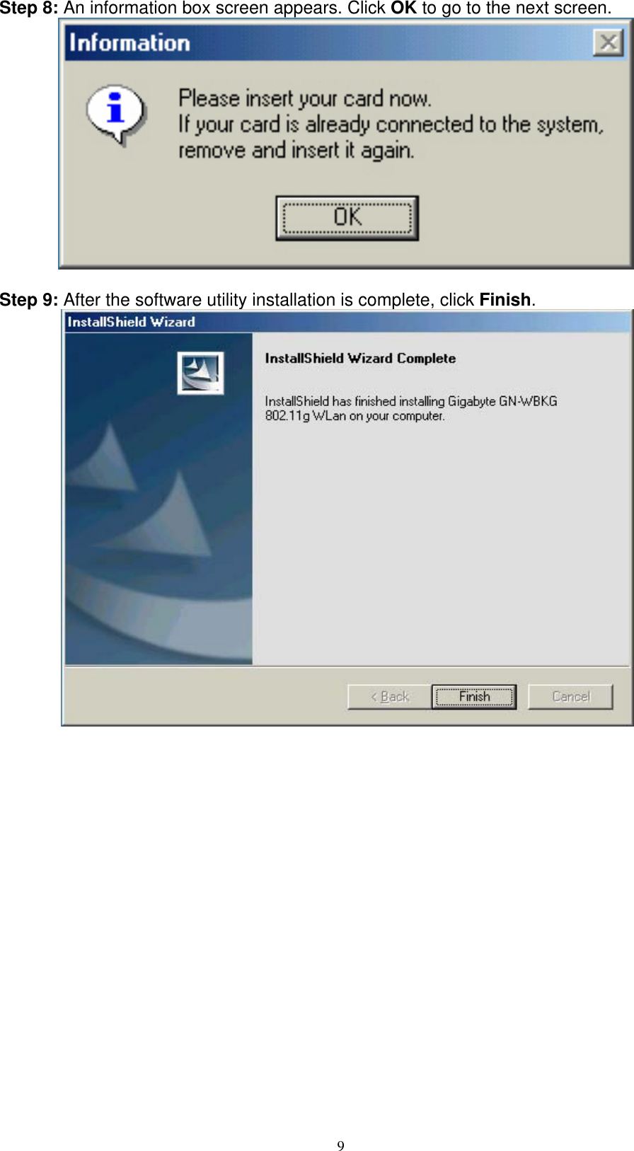
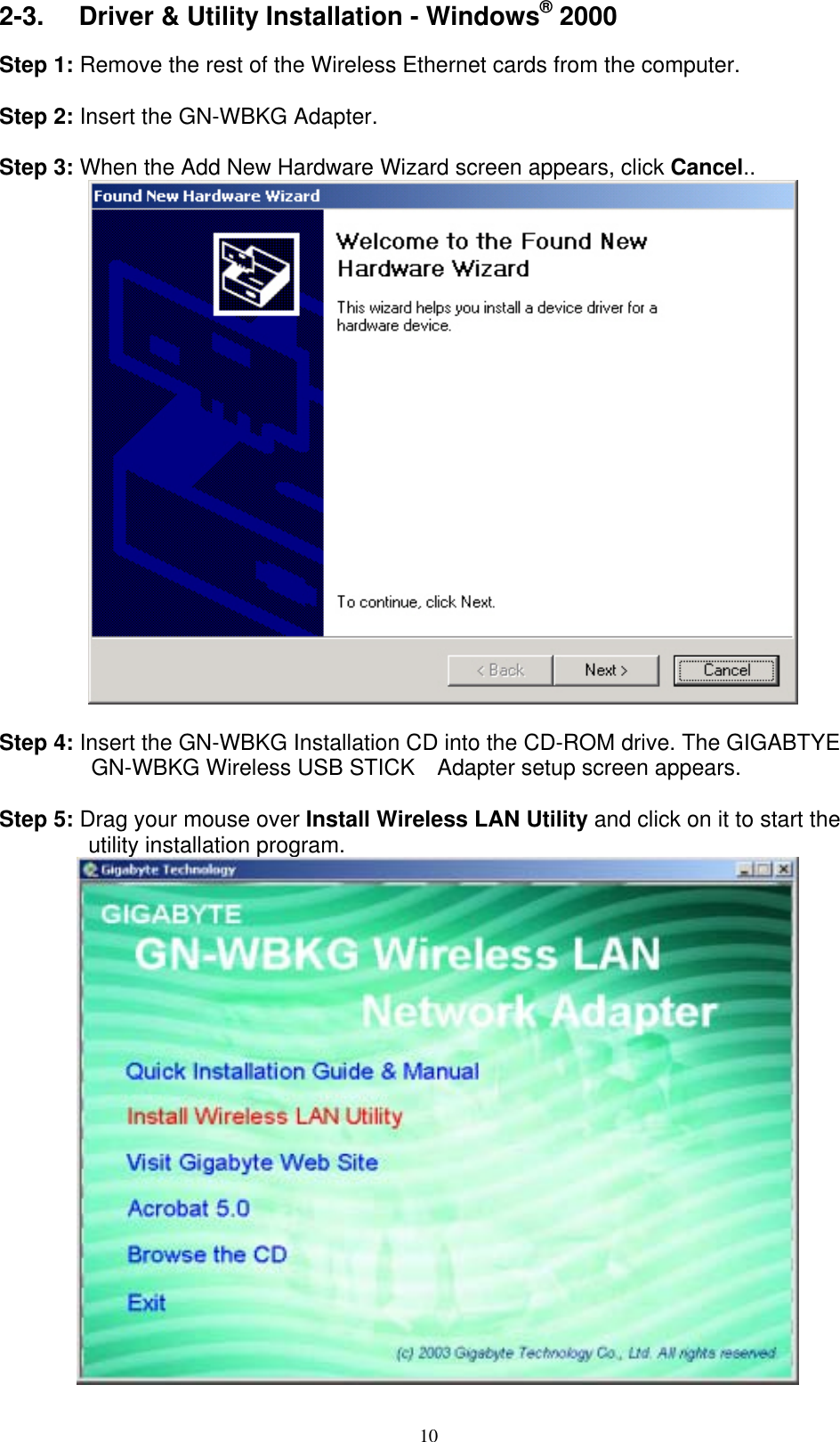
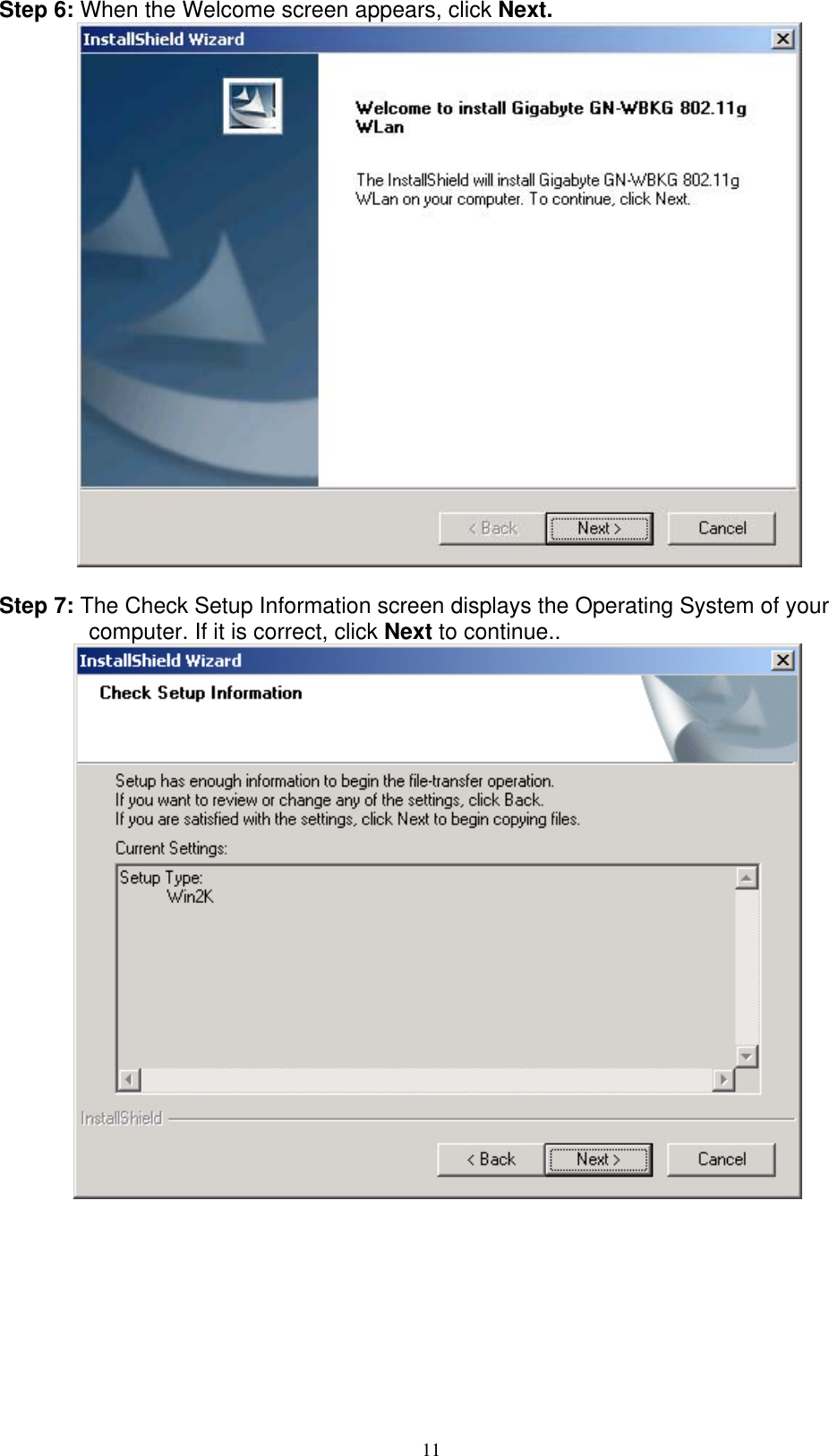
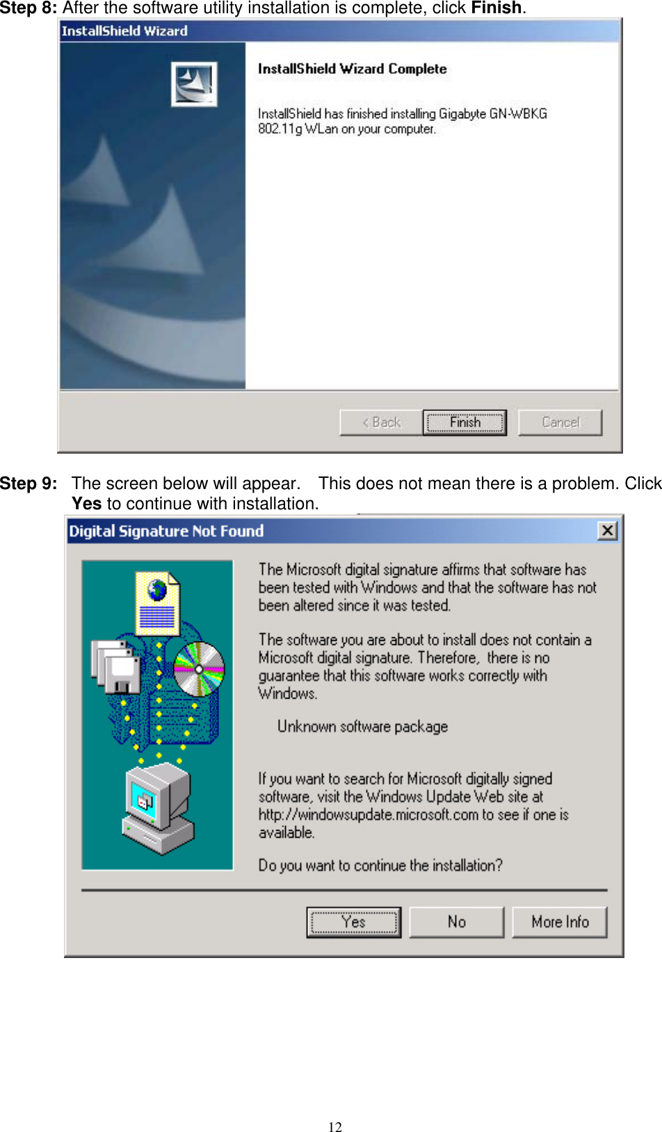
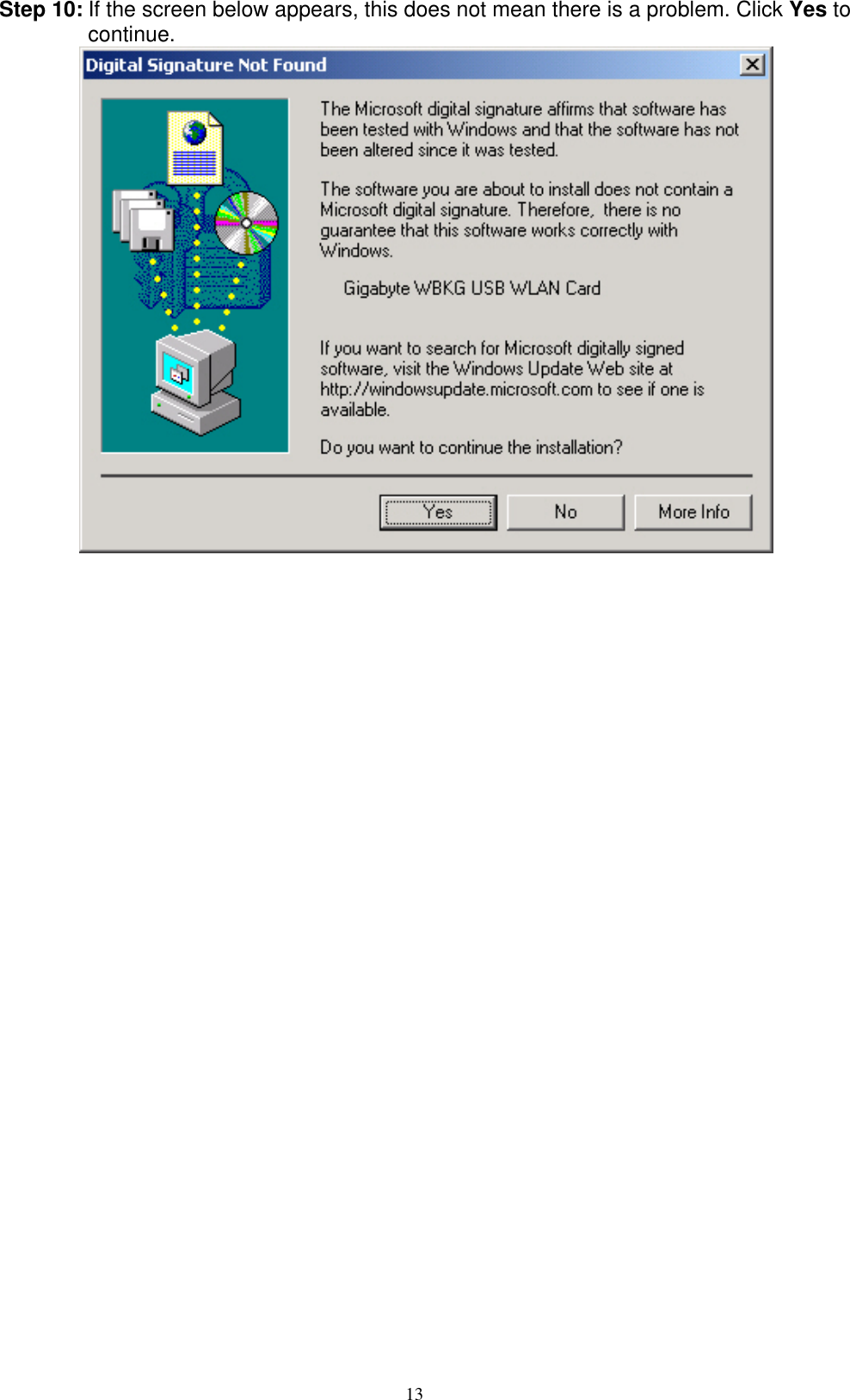
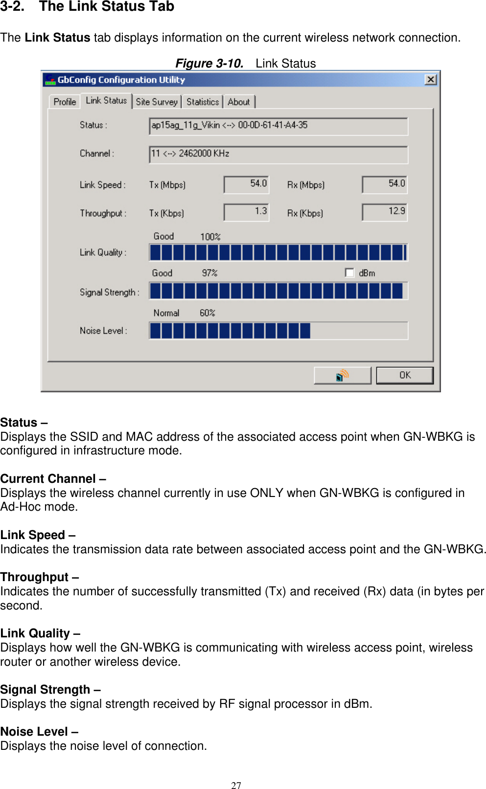
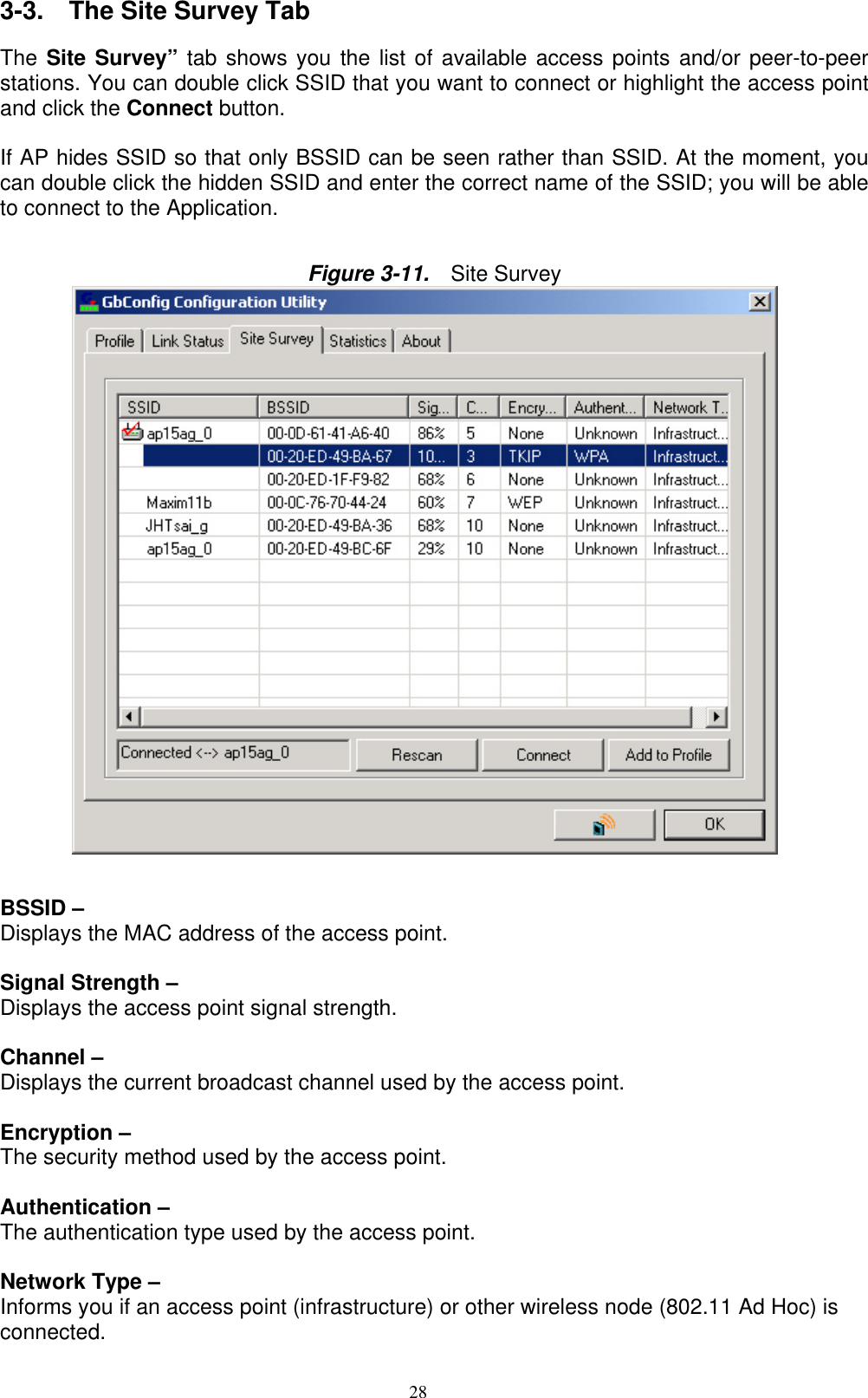
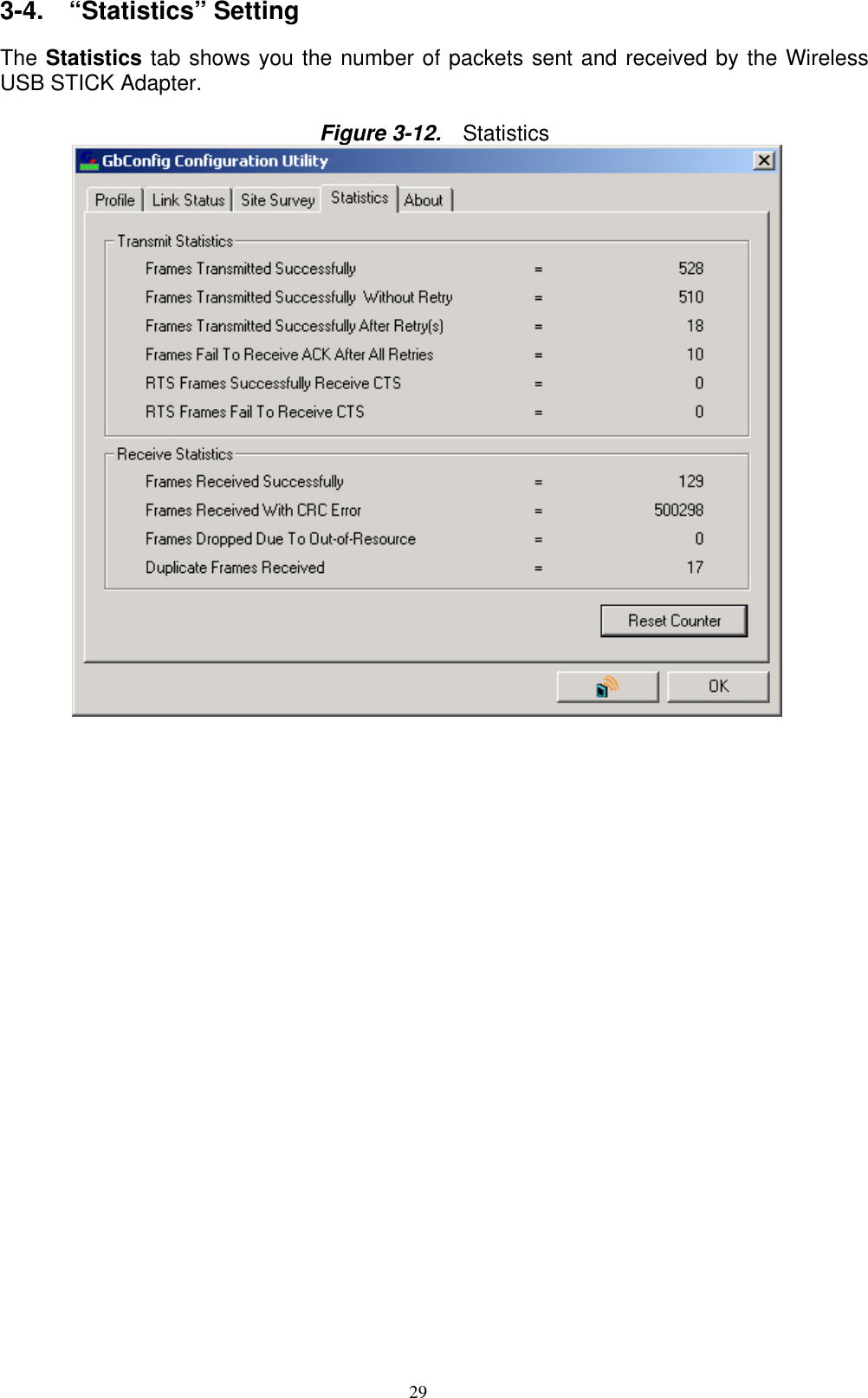
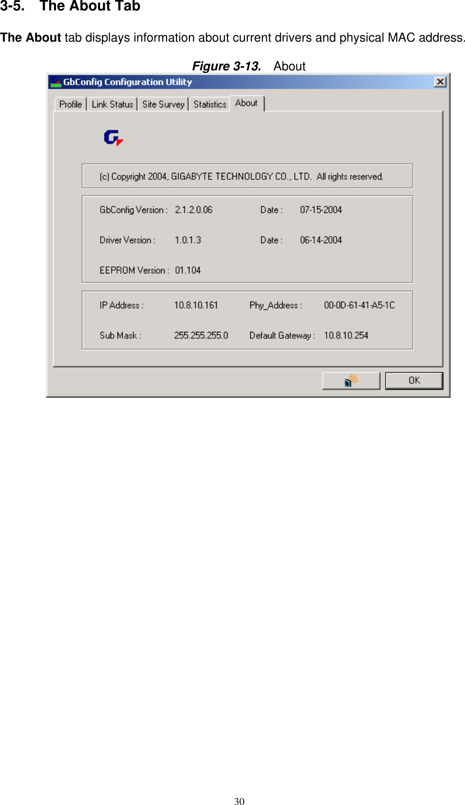
![22 1. Select a Key. (You may specify up to 4 Keys) 2. Select data type as either Hex or ASCII. (Hex = hexadecimal) 3. Enter a WEP key. [For 64-bit: 10 hexadecimal digits, 5 ASCII; For128-bit: 26 hexadecimal digits, 13 ASCII] 4. Click OK to save the settings. WPA-PSK Encryption – To activate WPA-PSK (Preshared Key) Encryption using TKIP or AES, choose WPA-PSK from the drop-down menu in the Encryption field. Then follow instructions below: 1. Enter a Preshared Key. [Key may be up to 64 hexadecimal digits or from 8 to 63 ASCII digits in length] 2. Click OK to save these settings. LEAP Authentication:enter account number and password.( AP must support this function) 3-1-2-2. 802.1X Setting To enable 802.1X Authentication, click on the Use 802.1x button (see Figure 3-5 above) and the 802.1X Setting window will open. From the 802.1x Setting window you can configure authentication parameters such as Tunnel Protocol, ID and Password and Client Certificate or Certificate Chain. Figure 3-6 802.1X Setting – Certification Tab Authentication Type – Choose authentication type from the drop-down menu. Authentication types supported include PEAP, TLS/Smart Card, TTLS, and MD5-Challenge.](https://usermanual.wiki/GIGA-BYTE-TECHNOLOGY/GN-WBKG/User-Guide-455992-Page-25.png)