GIGA BYTE TECHNOLOGY GN-WIAG01 IEEE 802.11b/g Wireless LAN Mini-PCI Card User Manual
GIGA-BYTE TECHNOLOGY CO., LTD. IEEE 802.11b/g Wireless LAN Mini-PCI Card
UserManual.wiki
>
GIGA BYTE TECHNOLOGY
>
GN WIAG01 User Manual
User Manual
Navigation menu
Upload a User Manual
Namespaces
Wiki Guide
HTML
PDF
Info
Views
User Manual
Discussion / Help
Navigation
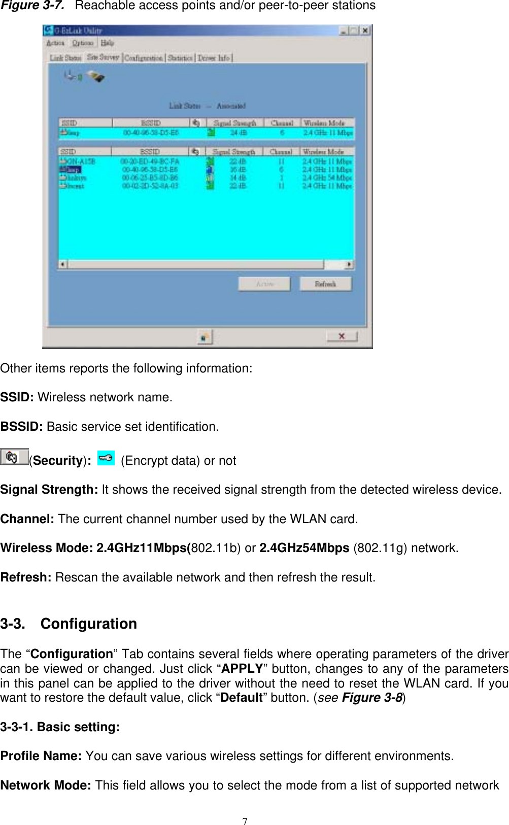
![6 Figure 3-5 Disabled WLAN Card. Figure 3-6 Enabled WLAN Card. Other items reports the following information: Association State: The field shows you if WLAN card is communicating with an access point or peer-to peer group. MAC Address: This card’s physical address. Channel [Freq]: The current channel and center frequency used by the WLAN card. Security: The current security setting. IP Address: WLAN Card IP Address. Profile: various wireless settings for different environments. SSID: Wireless network name. BSSID: Basic service set identification. Type: The current network type. Country: Language. 3-2. Site Survey The “Site Survey” tab shows you the list of reachable access points and/or peer-to-peer stations. In Fig 3-7, the card three 802.11b and one 802.11g wireless devices.](https://usermanual.wiki/GIGA-BYTE-TECHNOLOGY/GN-WIAG01/User-Guide-395498-Page-9.png)