GIGA BYTE TECHNOLOGY GN-WLMR101 802.11b Cardbus Wireless LAN Card User Manual Manual
GIGA-BYTE TECHNOLOGY CO., LTD. 802.11b Cardbus Wireless LAN Card Manual
Manual

GN-WLMR101
IEEE 802.11b Cardbus Wireless LAN Card
User’s Manual
http://www.gigabyte.com.tw
Rev. 1.0 First Edition
Contents
CHAPTER 1. PRODUCT OVERVIEW ..........................................................................................1
1-1. INTRODUCTION TO THE WIRELESS LAN CARD...............................................................1
1-2. FEATURES .................................................................................................................1
1-3. PHYSICAL DIMENSIONS/PACKAGING.............................................................................1
1-4. LED INDICATING LIGHT...............................................................................................2
1-5. SYSTEM REQUIREMENTS ............................................................................................2
1-5-1. Supported Platform.........................................................................................................2
1-5-2. Supported Operation System........................................................................................2
CHAPTER 2. INSTALLING THE WIRELESS LAN CARD........................................................3
2-1. INSTALLING THE DRIVER & UTILITY ............................................................................3
CHAPTER 3. USING THE UTILITY...............................................................................................5
3-1. CONFIGURATION........................................................................................................7
3-2. Advance Configuration …………………..…………………...…………………………7
3-3. STATUS …...………………………...………………………………...……………………8
3-4. STATISTICS ...............................................................................................................9
3-5. ABOUT ……………………..………………………………………………………………9
CHAPTER 4. SPECIFICATIONS .................................................................................................11
1
Chapter 1. Product Overview
1-1. Introduction to The Wireless LAN Card
This wireless Local Area Network (LAN) card is composed of the IEEE 802.11b MAC with
CARDBUS interface, Baseband, radio components, and two built-in antennas. This
product adopts the direct sequence spread spectrum (DSSS) technology using the
DBPSK, DQPSK, and CCK modulations to provide a very stable wireless communication
quality and an excellent signal receiver capability.
This product features the compact size, low power consumption, and power management
functions, and provides a high-speed wireless data communication. Therefore, this
product is ideally suitable for being integrated into the personal mobile and handheld
platform.
1-2. Features
Conforms to IEEE 802.11b specification.
Transmits data rate up to the maximum speed of 11Mbps.
Dynamically scales the data rate to 11, 5.5, 2, and 1Mbps.
Automatic power management to reduce battery consumption.
Built-in diversity antenna.
Supports 64-bit /128-bit WEP encryption.
Driver supports Windows 98SE/Me and Windows2000/XP.
1-3. Physical Dimensions/Packaging
Dimensions: 118mm * 54mm * 5mm
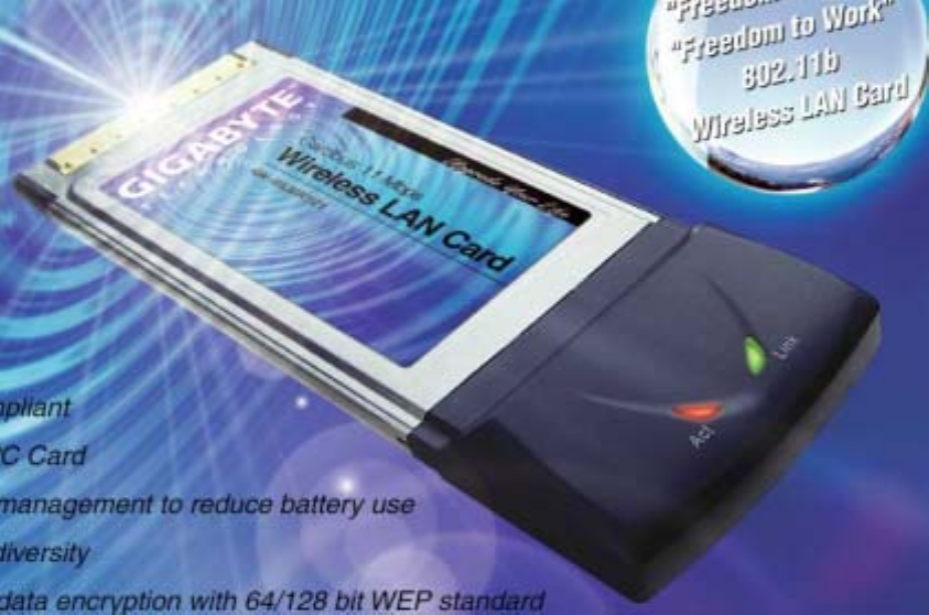
This wireless LAN card conforms to the PC card Type II standard. There are two
LED-indicating lights to indicate Act/Link status.

2
1-4. LED Indicating Light
Link: The Link LED lights up when the adapter has an active connection. If the LED
isn’t on, the adapter isn’t interfacing with the network.
Act: Blinking of the Act LED indicates that both transmit and receive activity is
occurring.
1-5. System Requirements
1-5-1. Supported Platform
IBM PC/AT compatible computer
1-5-2. Supported Operation System
Windows 98SE/Me
Windows 2000/XP
3
Chapter 2. Installing the Wireless LAN Card
2-1. Installing The Driver & Utility
Step 1: Please make sure that you don’t plug your card yet.
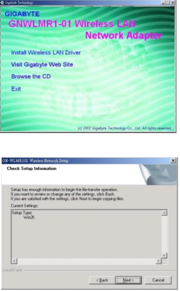
Step 2: Insert our setup CD into your CDROM drive, the following window will pop up.
Step 3: Click “Install Wireless LAN Driver”.
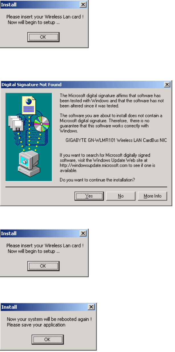
Step 4: Click “Next”.
4
Step 5: Insert your wireless LAN card, wait a moment, and then the following window will
pop up.
Step 6: Click “Yes”.
Step 7: Click “OK”.
Step 8: Click “OK”, and then your installation is ok.
5
Chapter 3. Using The Utility
The Configuration & Monitor Utility is a powerful application that helps you to configure the
card and monitor the statistics of the communication. Unlike the standard method of
configuring the card via the operating system utilities (e.g. Control Panel), this application
permits the dynamic modification of the configuration parameters while the card is
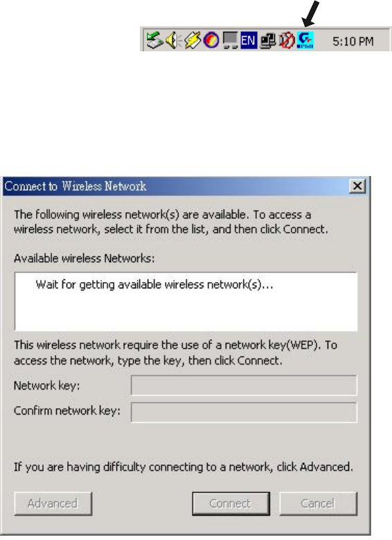
operating. It also offers some more configuration options. It appears as an icon on the
system tray of Windows every time the card is running (see Figure 3-1).
Figure 3-1. The icon of the Configuration & Monitor Utility
If this is your first time to use this card, you must start our utility and try to connect to any
available wireless networks. You can open it by double-clicking on this icon, the following
window will pop up.
Figure 3-2. Search for available wireless networks
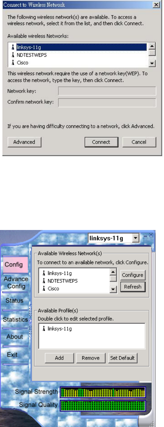
After this card finds all available wireless networks, the following window will pop up.
6
Figure 3-3. All available wireless networks
You can choose any available network and click “Connect” to join it. If this network had
built a security mechanism, you must to enter a correct security key (eg. WEP) before click
“Connect”.
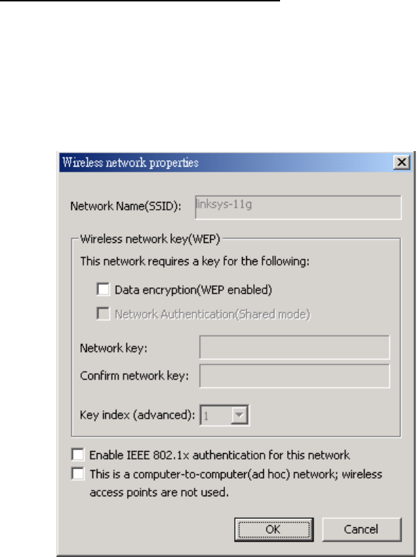
If you don’t know which network to join, or you want to configure and monitor your network,
you can click “Advanced” to go into the following window.
Figure 3-4. Configuration
7
Signal Strength: It shows the received signal strength from the detected wireless device.
Signal Quality: It shows the quality of communication between the wireless LAN card and
the associated network (In Figure 3-4, it mean linksys-11g).
3-1. Configuration
The “Config” Tab contains several fields where operating parameters of the driver can be
viewed or changed.
3-1-1 Available Wireless Networks:
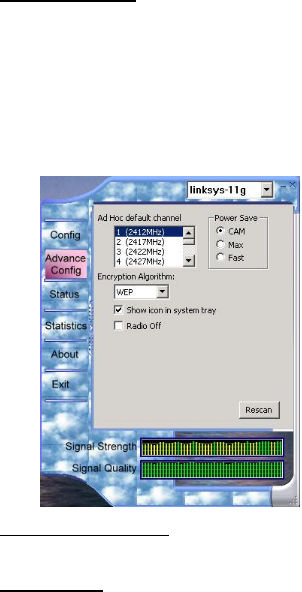
In this field, you can see all available wireless networks. In order to change the
configuration parameters, select a wireless network and then click the “Configure” button,
the following window will pop up. Make your changes and then click “OK” in order to save
your changes.
Figure 3-5. Wireless network properties
SSID: Network name.
WEP:
To prevent unauthorized user to access the data on wireless stations, the WLAN Card
offers a secure data encryption, known as WEP (Wired Equivalent Privacy). When you
select this item, the target 802.11 device must has the same encryption keys and be
configured to use encryption in order to communicate with each other. To configure your
WEP encryption, please click “Data encryption “ and enter a network key.
For 64-bit encryption, enter 10 digitals by Hex.
For 128-bit encryption, enter 26 digitals.
Click “OK” to save these settings.
8
3-1-2 Available Profiles:
In this field, you can click “Add” to add a available network into your available profiles. You
also can click “Remove” to delete this profile or click “Set Default” to set a default
associated network. Every time this card is active, it will automatically try to connect to this
default network.
3-2. Advance Configuration
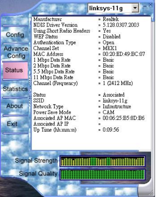
The “Advance Config” Tab contains several fields where operating parameters of the
driver can be viewed or changed. See figure 3- 6.
Figure 3-6. Advance configuration
3-2-1 Ad Hoc default channel:
In this field, You can select a communication channel.
3-2-2 Power Save:
CAM (Constantly Awake Mode): CAM is the normal mode for desktop PC or other
machines where power consumption is not an issue. It keeps the radio powered up all the
time, so that there is little latency for responding to messages.
MAX (Max Power Savings Mode): If power consumption is a major concern for your
machine, you can select this to save power.
Fast (Power Save mode): Fast mode switches between Power Saving and CAM based
on network traffic. When receiving a large number of packets, this mode will temporarily
9
switch to CAM mode. Once these packets are retrieved, it switches back to Power Saving
status.
3-3. Status
The “Status” tab shows you the information and status of the card. See figure 3-7.
Figure 3-7. The information and status of the card
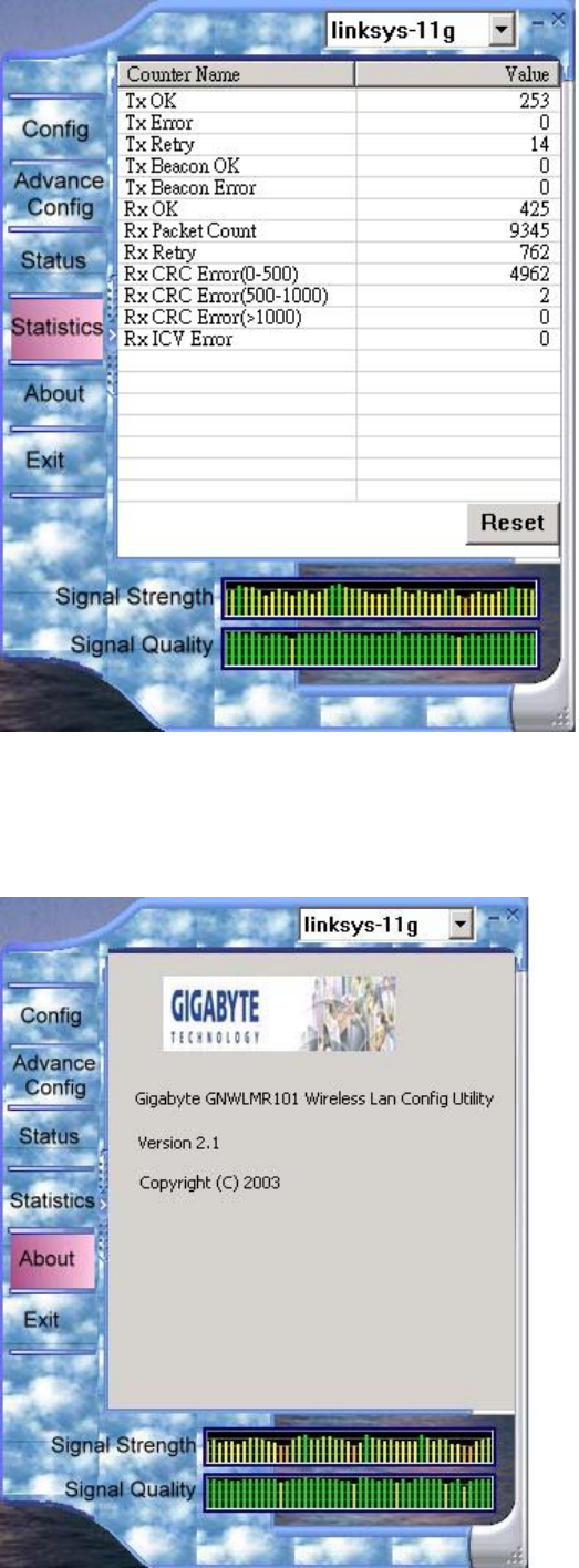
3-4. Statistics
This tab shows you the available statistic information. See figure 3-8.
10
Figure 3-8 The statistic information of packets sent and received by the card
3-5. About
This tab shows you the software driver’s version. See the following window.

11
Chapter 4. Specification
SYSTEM
Standards IEEE 802.11/802.11b
MAC/BBP Chip RTL8180
Host Interface CARDBUS
Modulation 1Mbps: DBPSK; 2Mbps: DQPSK; 5.5 and 11 Mbps: CCK
Data Rates 1, 2, 5.5, 11 Mbps
Operating Voltages 3.3V
Typical power consumption Transmit 290mA; receive 170mA; Sleep 23mA
Operating Range Open space: 100 - 300m; Indoor: 30 - 100m
RF CHARACTERISTICS
Frequency Band 2.400 ~ 2.4835 GHz (subject to local regulation)
Radio Technology DSSS (Direct Sequence Spread Spectrum)
11 Channels (US, Canada) 4 channels (France)
Number of Channel 14 Channels (Japan) 13 Channels (Most European countries, ETSI)
Output power 20 dBm @ nominal temperature
Receive Sensitivity minimum - 81dBm @ 11 Mbps; typical – 84dBm @ 11 Mbps
Antenna Two internal antenna supporting diversity
REGULATOORY and ENVIRONMENTAL COMPLIANCE
FCC part 15 (USA)
EMC certification CE (Europe)
Temperature Range Operating: 0 ~ 55 deg C, Storage: -20 ~ 65 deg C
Humidity Max. 90% Non-condensing
SOFTWARE/FEATURES
Platforms Windows 98SE, ME, 2000 and XP
Roaming Full mobility and seamless roaming
Security 64 and 128 bit WEP
Management Utility Link Configuration for network join and statistics
PHYSICAL SPECIFICATION
Dimensions 118mm x 54mm x 5mm
Weight 39 g
Packaging Generic, Gigabyte, private labeling optional
LED indicator Two LEDs indicating Activity/Link
12
Federal Communication Commission Interference Statement
This equipment has been tested and found to comply with the limits for a Class B digital
device, pursuant to Part 15 of the FCC Rules. These limits are designed to provide
reasonable protection against harmful interference in a residential installation. This
equipment generates, uses and can radiate radio frequency energy and, if not installed
and used in accordance with the instructions, may cause harmful interference to radio
communications. However, there is no guarantee that interference will not occur in a
particular installation. If this equipment does cause harmful interference to radio or
television reception, which can be determined by turning the equipment off and on, the
user is encouraged to try to correct the interference by one of the following measures:
- Reorient or relocate the receiving antenna.
- Increase the separation between the equipment and receiver.
- Connect the equipment into an outlet on a circuit different from that to which the receiver
is connected.
- Consult the dealer or an experienced radio/TV technician for help.
FCC Caution: To assure continued compliance, (example - use only shielded interface
cables when connecting to computer or peripheral devices) any changes or modifications
not expressly approved by the party responsible for compliance could void the user's
authority to operate this equipment.
This device complies with Part 15 of the FCC Rules. Operation is subject to the following
two conditions: (1) This device may not cause harmful interference, and (2) this device
must accept any interference received, including interference that may cause undesired
operation.
IMPORTANT NOTE:
FCC Radiation Exposure Statement:
This equipment complies with FCC radiation exposure limits set forth for an uncontrolled
environment. End users must follow the specific operating instructions for satisfying RF
exposure compliance.
This transmitter must not be co-located or operating in conjunction with any other antenna
or transmitter.
This device complies with FCC RF Exposure limits set forth for an uncontrolled environment,
under 47 CFR 2.1093 paragraph (d)(2). End-users must be provided with specific operating
instructions for satisfying RF exposure compliance."