GIGA BYTE TECHNOLOGY GN-WP01GS PCI Wireless Adapter User Manual GN WP01GS
GIGA-BYTE TECHNOLOGY CO., LTD. PCI Wireless Adapter GN WP01GS
UserManual.wiki
>
GIGA BYTE TECHNOLOGY
>
GN WP01GS User Manual
Users Manual
Navigation menu
Upload a User Manual
Namespaces
Wiki Guide
HTML
PDF
Info
Views
User Manual
Discussion / Help
Navigation

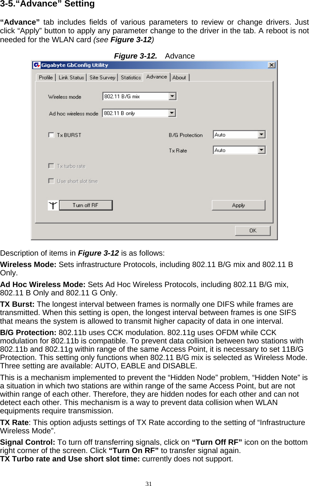
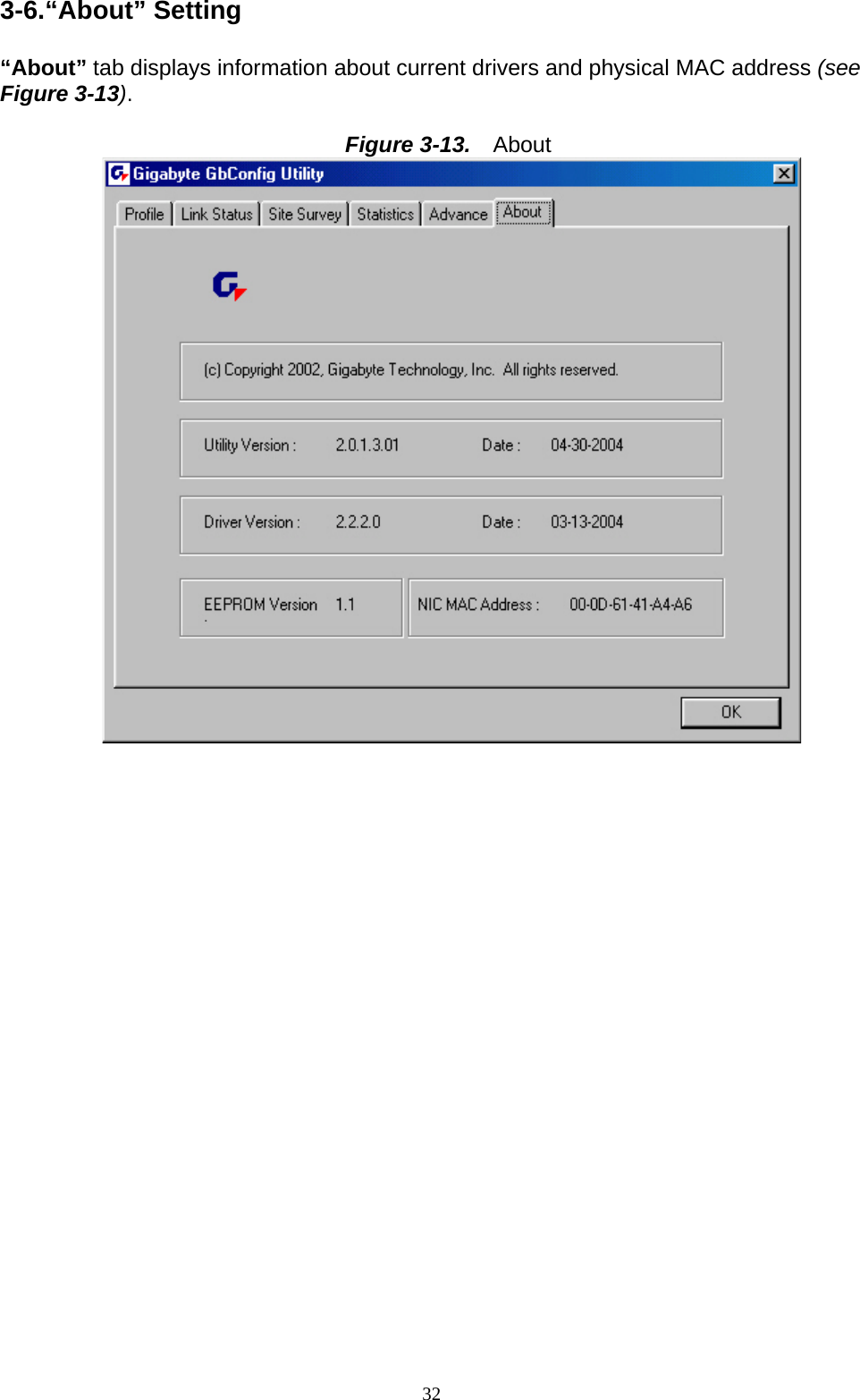
![30 3-4.“Statistics” Setting “Statistics” tab shows you the number of packets sent and received by the card (see Figure 3-11) Figure 3-11. Statistics Description of items in Figure 3-11 is as follows: Frames Transmitted Successfully: Number of frames transmitted successfully. Frames Transmitted Successfully Without Retry: Number of frames transmitted successfully, excluding packets transmitted successfully with more than one retry. Frames Transmitted Successfully After Retry[s]: Number of frames transmitted successfully with more than one retry. Frames Fail To Receive ACK After All Retries: Number of frames failing to receive ACK after many retries. RTS Frames Successfully Receive CTS: Number of RTS frames successfully received CTS (Clear To Send) from AP. RTS Frames Fail To Receive CTS: Number of RTS frames fail to receive CTS from AP. Frames Receive Successfully: Number of frames received successfully. Frames Receive With CRC Error: Number of frames received with CRC Errors. Frames Dropped Due TO Out-of-Resource: Number of frames dropped due to out-of-resource. Duplicate Frames Received: Number of duplicate frames received. Reset Counter: Resets the counter to zero.](https://usermanual.wiki/GIGA-BYTE-TECHNOLOGY/GN-WP01GS/User-Guide-548173-Page-33.png)