GIGA BYTE TECHNOLOGY GN-WP01GT 802.11bg PCI Wireless LAN Card User Manual GN WP01GT EN
GIGA-BYTE TECHNOLOGY CO., LTD. 802.11bg PCI Wireless LAN Card GN WP01GT EN
UserManual.wiki
>
GIGA BYTE TECHNOLOGY
>
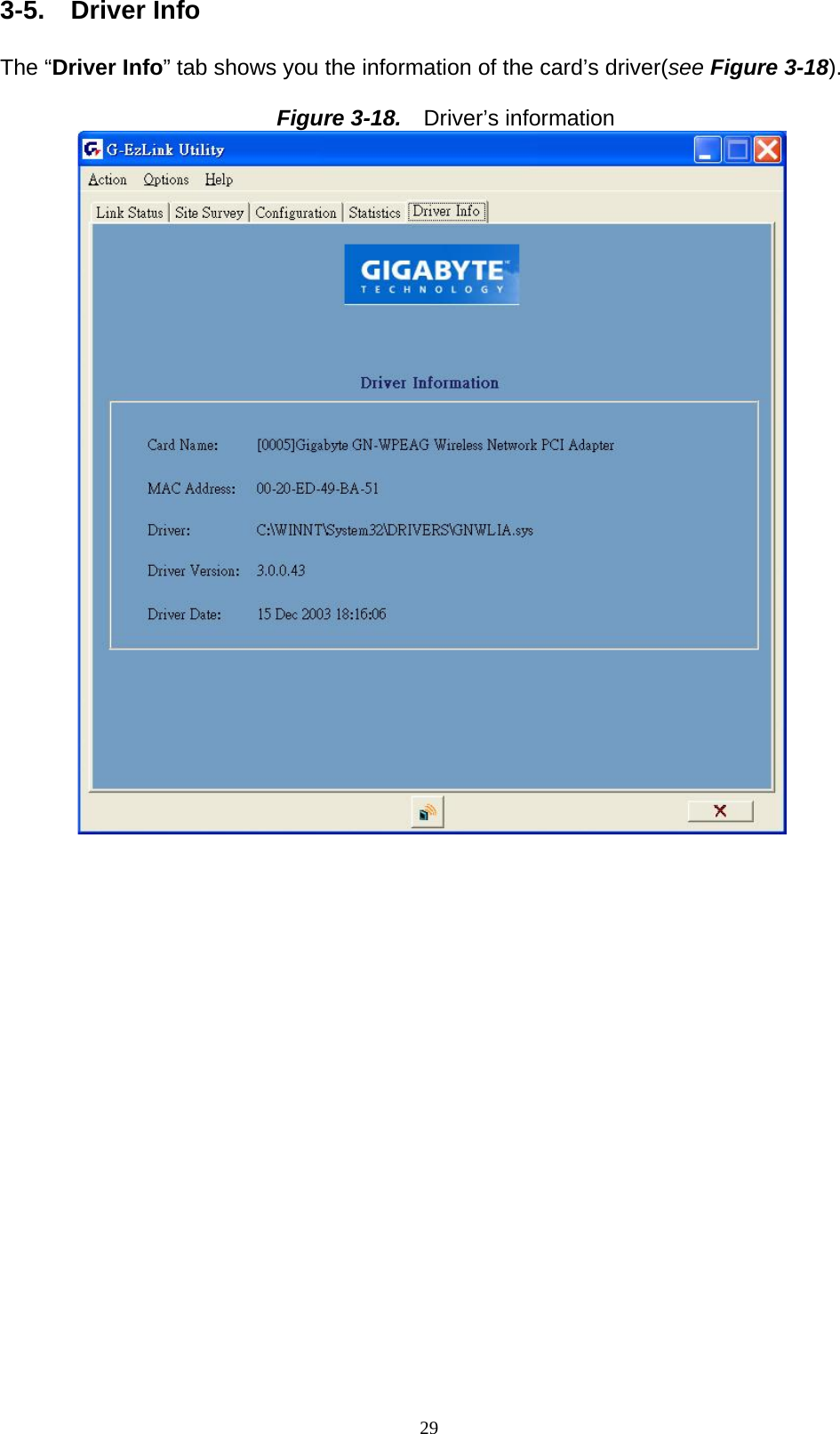
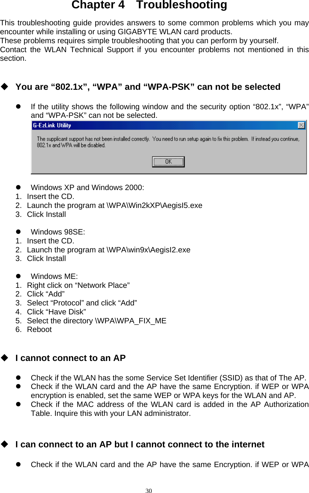
GN-WP01GT User Manual
>
users manual rev
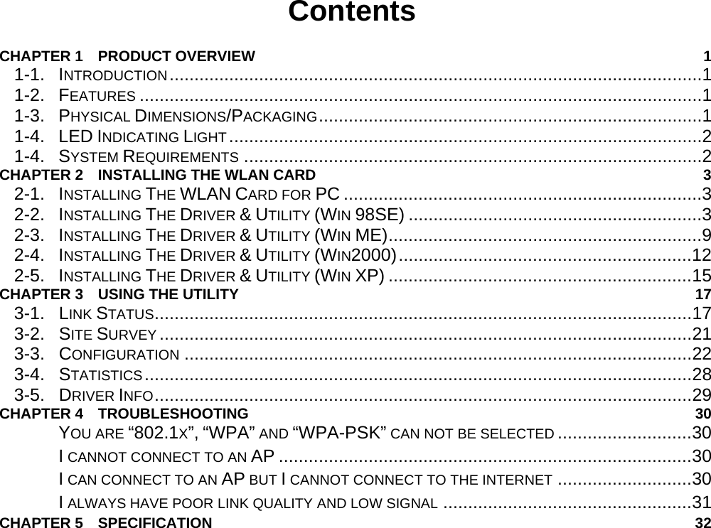
Contents
1.
users manual rev
2.
Revised Manual
users manual rev
Navigation menu
Upload a User Manual
Namespaces
Wiki Guide
HTML
PDF
Info
Views
User Manual
Discussion / Help
Navigation
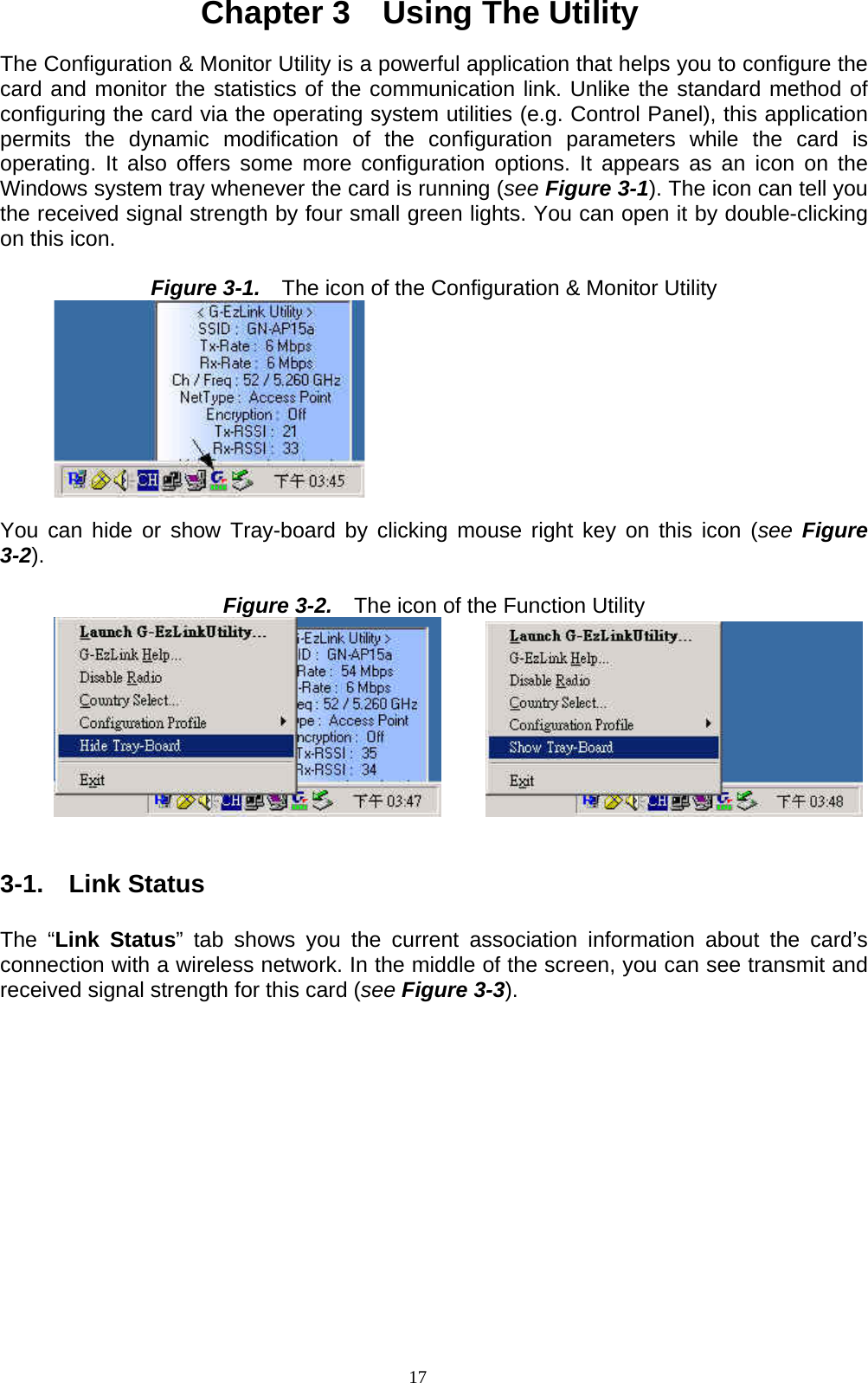
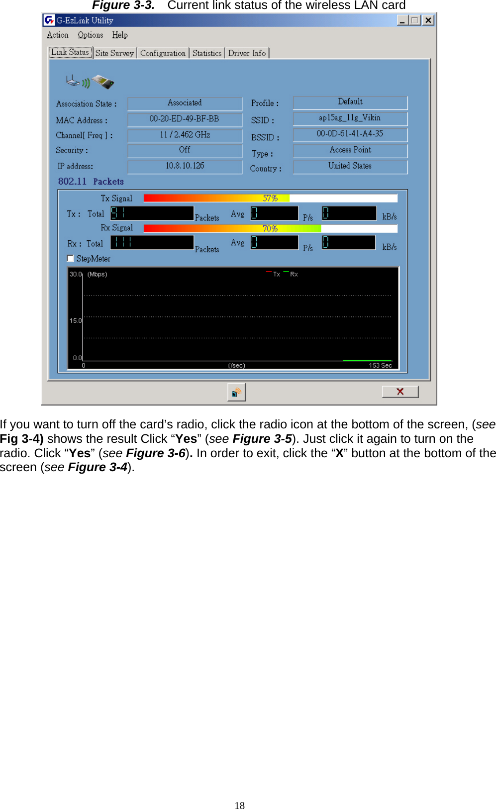
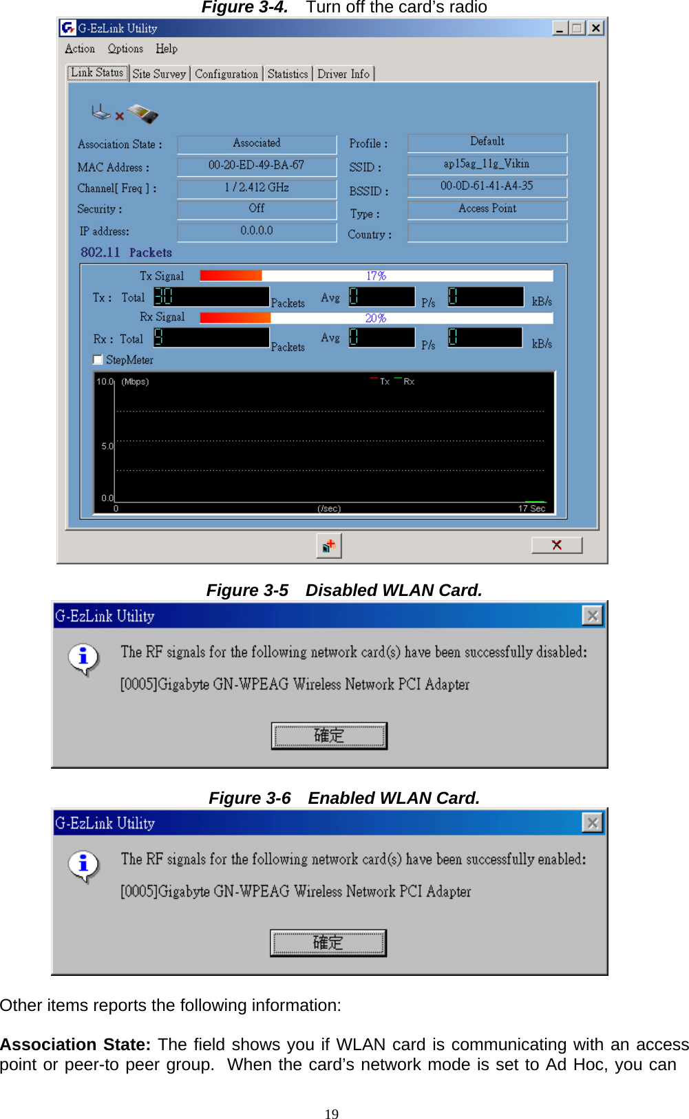
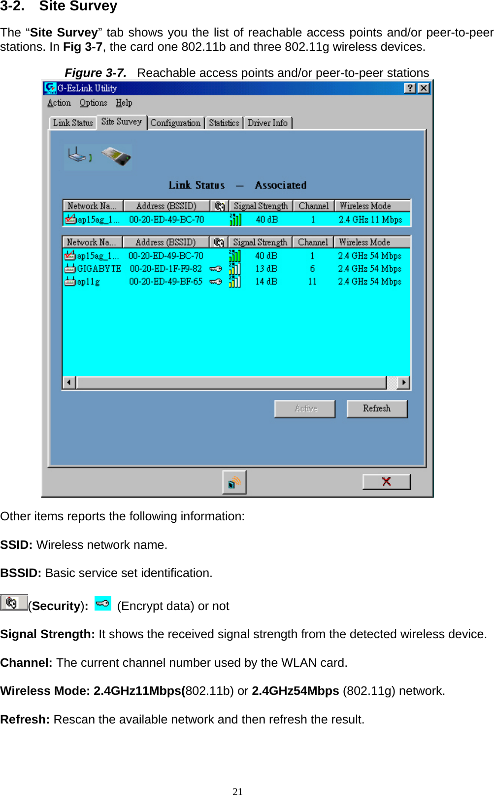
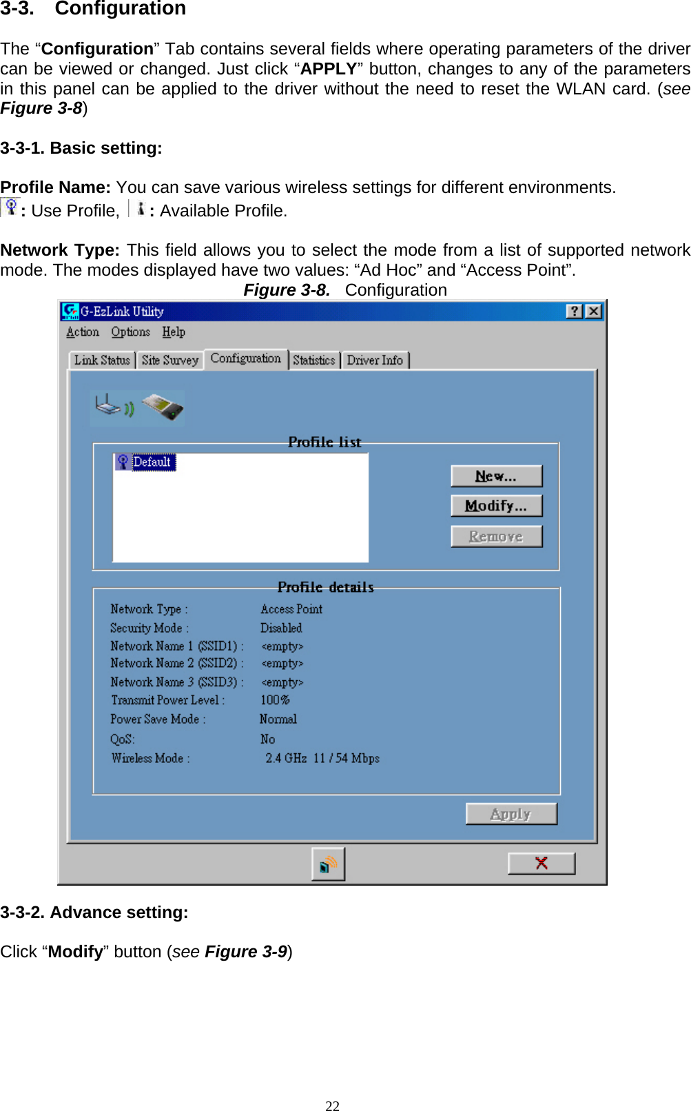
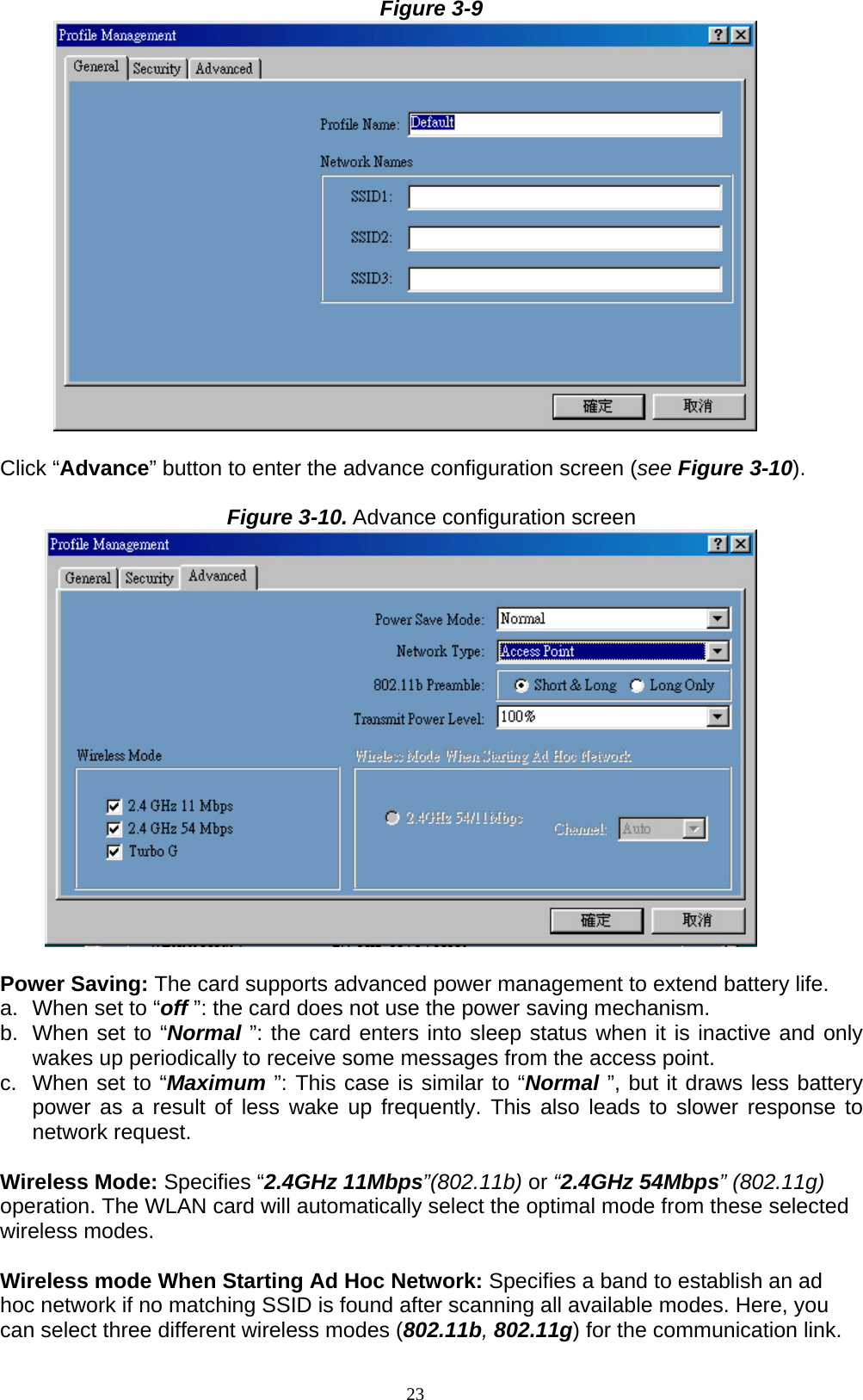
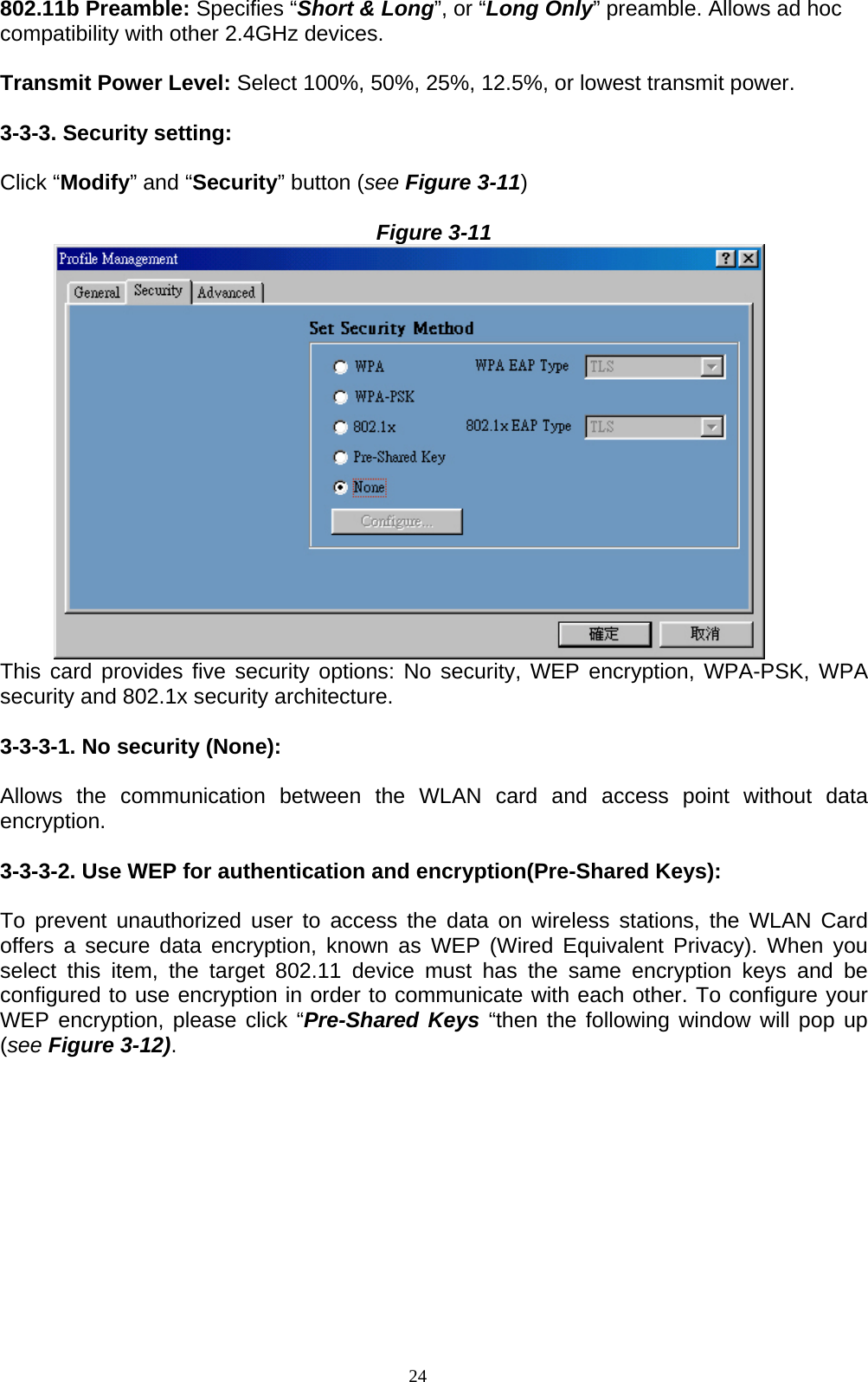
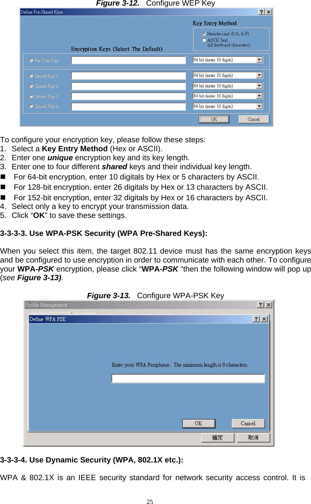
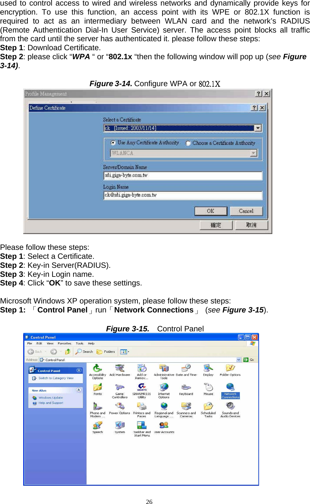
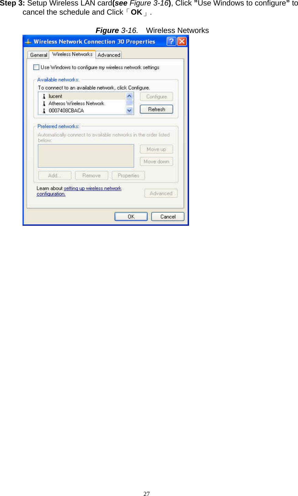
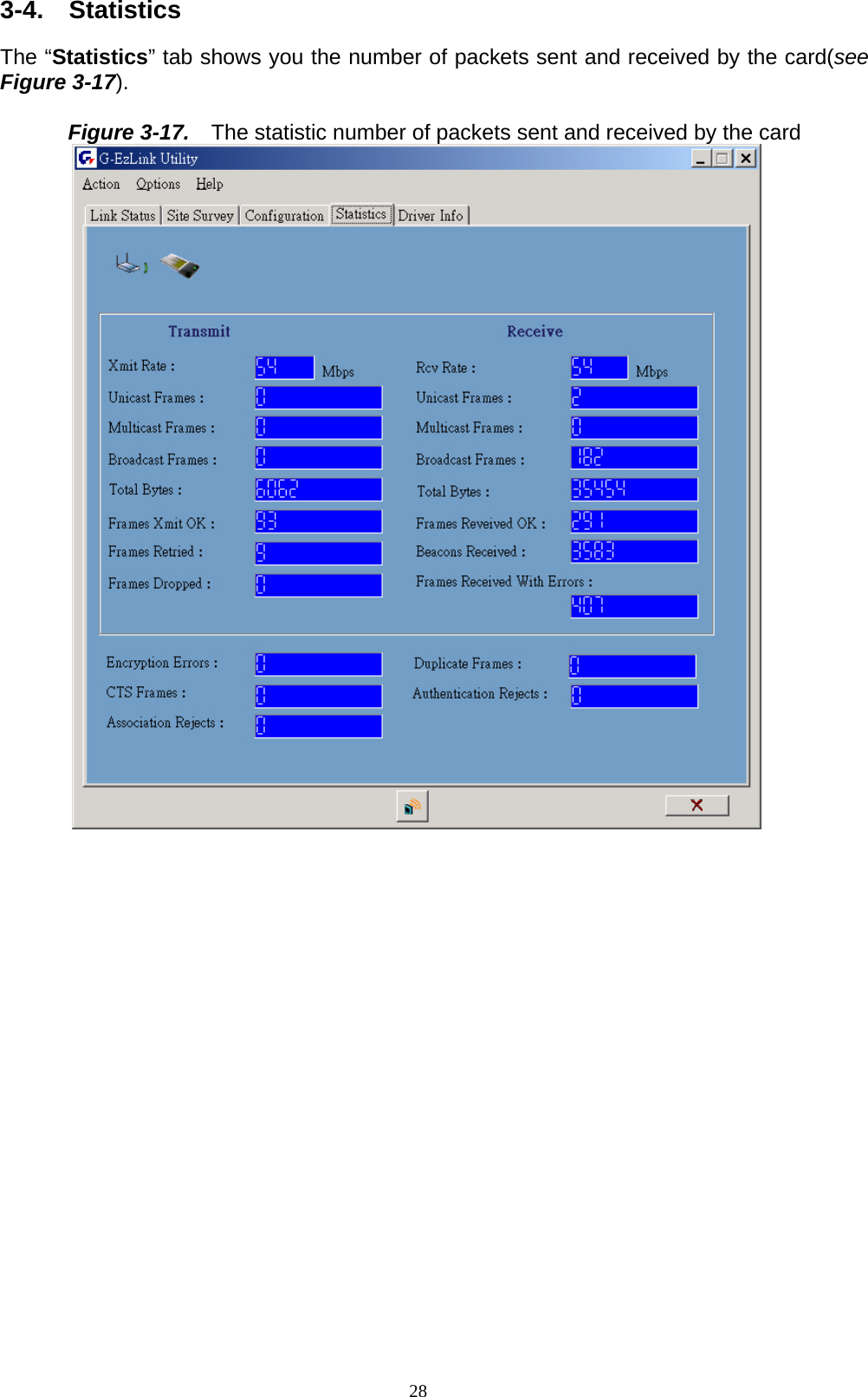
![20 select a channel from the AD Hoc channel drop-down menu for your Ad Hoc group to use. MAC Address: This card’s physical address. Channel [Freq]: The current channel and center frequency used by the WLAN card. Security: The current security setting. IP Address: WLAN Card IP Address. Profile: various wireless settings for different environments. SSID: Wireless network name. This is the wireless network name expressed as text string that all members within the same network share. Devices that don’t share the same network name cannot communicate with each other. BSSID: Basic service set identification. Type: The current network type.](https://usermanual.wiki/GIGA-BYTE-TECHNOLOGY/GN-WP01GT.users-manual-rev/User-Guide-541371-Page-23.png)