GIGA BYTE TECHNOLOGY GN-WPMG PCI Wireless LAN Card User Manual 2
GIGA-BYTE TECHNOLOGY CO., LTD. PCI Wireless LAN Card 2
Users Manual
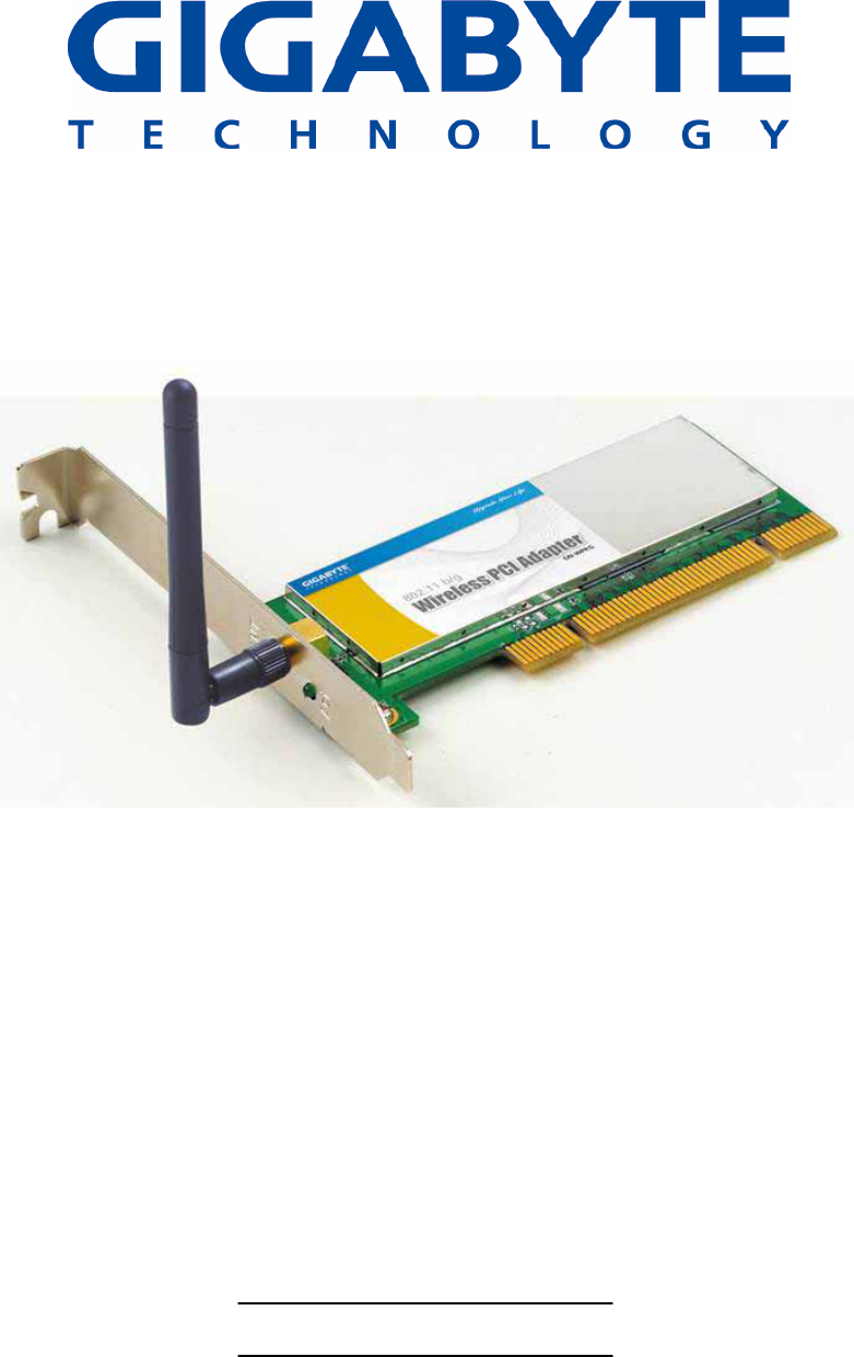
PCI Wireless LAN Card
GN-WPMG
User’s Manual
http://www.gigabyte.com.tw
Version 3.0
Federal Communication Commission Interference Statement:
This equipment has been tested and found to comply with the limits for a Class B digital
device, pursuant to Part 15 of the FCC Rules. These limits are designed to provide
reasonable protection against harmful interference in a residential installation. This
equipment generates, uses and can radiate radio frequency energy and, if not installed
and used in accordance with the instructions, may cause harmful interference to radio
communications. However, there is no guarantee that interference will not occur in a
particular installation. If this equipment does cause harmful interference to radio or
television reception, which can be determined by turning the equipment off and on, the
user is encouraged to try to correct the interference by one of the following measures:
• Reorient or relocate the receiving antenna.
• Increase the separation between the equipment and receiver.
• Connect the equipment into an outlet on a circuit different from that to which the
receiver is connected.
• Consult the dealer or an experienced radio/TV technician for help.
FCC Caution:
To assure continued compliance, any changes or modifications not expressly approved by
the party responsible for compliance could void the user's authority to operate this
equipment.
This device complies with Part 15 of the FCC Rules. Operation is subject to the following
two conditions: (1) This device may not cause harmful interference, and (2) this device
must accept any interference received, including interference that may cause undesired
operation.
IMPORTANT NOTE
FCC Radiation Exposure Statement:
This equipment complies with FCC radiation exposure limits set forth for an uncontrolled
environment. End users must follow the specific operating instructions for satisfying RF
exposure compliance.
This transmitter must not be co-located or operating in conjunction with any other antenna
or transmitter.
Contents
CHAPTER 1 PRODUCT OVERVIEW...........................................1
1.1 INTRODUCTION TO THE GN-WPMG WIRELESS PCI ADAPTER .......................................1
1.2 FEATURES .................................................................................................................1
1.3 PHYSICAL DIMENSIONS & PACKAGING..........................................................................1
1.4 LED INDICATOR .........................................................................................................2
1.5 SYSTEM REQUIREMENTS ............................................................................................2
CHAPTER 2 INSTALLATION.......................................................3
2-1. INSTALLING THE ADAPTER (HARDWARE INSTALLATION)..................................................3
2-2. INSTALLING THE DRIVER & UTILITY...............................................................................4
CHAPTER 3 USING THE WIRELESS CLIENT UTILITY.............8
3.1. CREATING A PROFILE .................................................................................................8
3.2. NETWORK STATUS TAB.............................................................................................13
3.3. SITE SURVEY TAB ....................................................................................................15
3.4. STATISTICS TAB .......................................................................................................17
3.5. ABOUT TAB..............................................................................................................18
APPENDIX A TROUBLESHOOTING.........................................20
APPENDIX B SPECIFICATIONS..................................................21
APPENDIX C REGULATORY INFORMATION ............................22
APPENDIX D WARRANTY...........................................................23

Chapter 1 Product Overview
1.1 Introduction to the GN-WPMG Wireless PCI Adapter
The GIGABYTE WPMG Wireless PCI Adapter installs quickly into your motherboard’s PCI slot, connecting
wirelessly to your Wi-Fi Router - instantly transforming your PC into a wireless AP, broadening the range of
your wireless network.
The WPMG is fully 802.11b interoperable, meaning it connects seamlessly to both 11b and 11g wireless
traffic, and with its dynamic speed adjustment feature, it will always connect at the highest possible speed –
up to 54Mbps.
The GIGABYTE WPMG Wireless G PCI Adapter makes connecting to a wireless router or access point a
cinch with its included Wireless Client that automatically detects and lists all available wireless networks.
Since the WPMG can be setup in Wireless Distribution System (WDS), it transforms your desktop into an
wireless access point, effectively expanding the range of your wireless network.
Secure
With its support for the highest level of encryption common today - 128 bit WEP, 802.1X, and WPA - the
WPMG is perfect for the home user, keeping your data secure.
Robust
Move huge files and digital video blazingly fast! Up to 5 times faster than the common 11b solution. The
high gain antenna and 802.11g wireless standard gives you continuous access to your home wireless router
or office network,
Convenient
Saves the time and expense of installing Ethernet cabling when you want to set up or expand a network, and
makes it simple to relocate your desktop PC.
1.2 Features
• Connects to any 802.11b, and 802.11g wireless network
• Data rates up to 54 Mbps*
• Switch between AP and Station mode using SoftAP
• Dynamic rate shifting ensures fastest possible connection
• External antenna
• Seamless roaming between wireless access points
• Supports AES (Advance Encryption System), enterprise-class 802.1x security
and multiple-levels WEP encryption (64-bit /128-bit/), and WPA (Wi-Fi Protected
Access)
*Note: Standards IEEE 802.11b and IEEE 802.11g specify that when in Ad-Hoc mode, wireless products
only support 11 Mbps. These IEEE standards apply to all 11b, 11g, and Super G products.
1.3 Physical Dimensions & Packaging
Dimensions: 134mm × 81mm × 22mm
1
Before beginning the installation procedures, please inspect the components to assure
that they have not been damaged during shipping. The components include:
Package Contents
• GN-WPMG PCI Adapter
• Low profile external antenna
• Setup CD
• Quick Start Guide
In case of any missing or damaged accessories, please contact your local distributor or
authorized reseller immediately. If you require returning the damaged product, you must
pack it in the original packing material or the warranty will be voided.
1.4 LED Indicator
The WPMG PCI Adapter has One LED light indicating Activity located on the outward
facing bracket frame.
1.5 System Requirements
For trouble free installation and operation, please assure your PC meets the following
minimum system requirements:
• Notebook or Desktop PC with a Pentium® 300 MHz or higher compatible processor
with an available PCI slot.
• A CD-ROM drive.
• 20 Mbytes of free hard disk space.
2
Chapter 2 Installation
This chapter covers the installation of the WPMG Adapter for your desktop PC. The
following sections will assist you with proper installation of the PCI Adapter, and also with
installing the necessary drivers and utilities. For specific information regarding your
Version of Windows, please refer to the appropriate sections as indicated
2-1. Installing the Adapter (Hardware Installation)
Step 1: Power off your PC.
Step 2: Plug the PCI Adapter into an open PCI slot on the motherboard by pressing the
card gently until the card edge connecter is completely and firmly inserted into
your motherboards PCI slot.
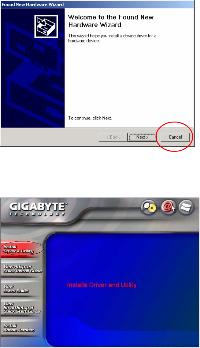
Step 3: Once inserted, attach the antenna on the mount of the PCI Adapter by screwing
it on clockwise as shown in the figure below.
Step 4: Power on your PC.
3
2-2. Installing the Driver & Utility
After restarting your computer the Windows Found New Hardware wizard will open.
When it does, please click Cancel to close it. GIGABYTE drivers and utilities offer more
power and control over your new WPMG PCI Adapter than does Windows native Zero
Configuration Utility.
Step 1: At the Found New Hardware Wizard screen, click Cancel.
Step 2: Insert the WPMG Setup CD into the CD-ROM drive. The WPMG Welcome
screen window will automatically open.
Step 3: From the main menu, click “Install Wireless LAN Utility”.
Step 4: InstallShield will install the WPMG drivers. Click Next to proceed.
4
Step 5: Setup will detect your version of Windows. Click Next.
5
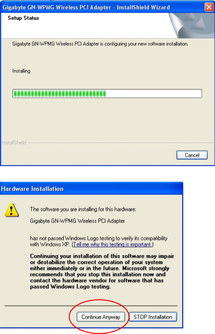
Step 6: Files will be copied and your system configured.
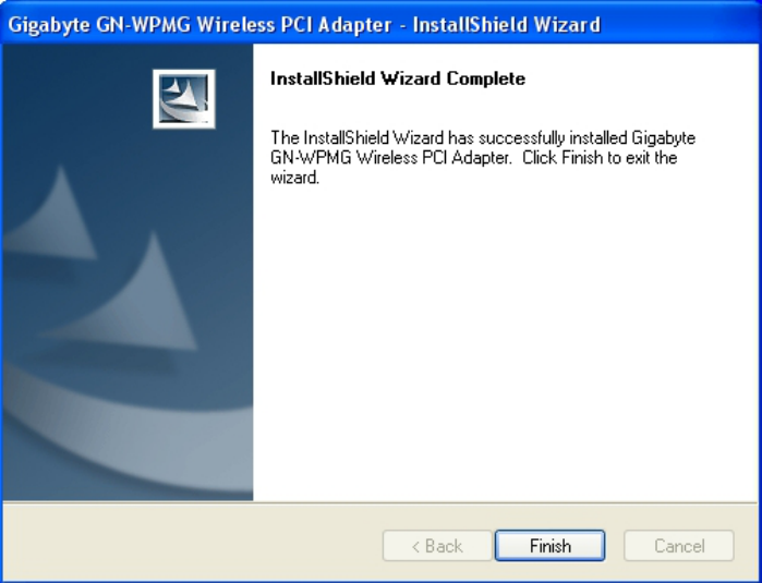
Step 7: At the Windows XP Logo testing message, Click Continue Anyway.
Step 8: When InstallShield has completed, click Finish to finish installation.
6
Installation of the GN-WPMG is complete.
7

Chapter 3 Using the Wireless Client Utility
The WPMG Wireless Utility is a powerful application that helps you to configure the
network card and monitor the statistics of the communication link.
It appears as a square icon (green when connected, red when not) in the task bar at the
bottom right corner of screen (see Figure 3-1).
Figure 3-1. WPMG Client Utility quick start icon
To open the WPMG Utility, either double click the quick start icon located in your system
tray, or from the Windows Start menu, select Programs, GIGABYTE Wireless Network
Adapters, GN-WPMG, and then GN-WPMG Utility.
Note: You may only use the utility to change wireless configurations when the WPMG
Adapter is enabled and operating. You have to use Windows native Zero Configuration
tool provided with Windows when the Adapter is not enabled.
3.1. Creating a Profile
The Profile Manager tab shows you the current association information about the profile.
(see Figure 3-2). Profiles are useful if you often associate with different access points.
You can configure a group of settings depending on the access point you often associate
with. and save as a profile, Click the Create button to create a new profile (see section
below for further details), When you have finished creating a profile, return to Profile
Manager Screen and click the Apply Profile button to have a selected profile become
active.
8
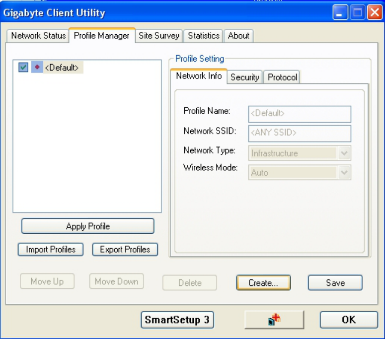
Figure 3-2. Profile Manager
Description of items in Figure 3-2 is as follows:
Profile Setting
A profile can be saved for various wireless settings in different environments, i.e.
home, office, or the coffee shop. Every session uses a profile (even if it’s the
Default profile). To Create a new profile, just click the “Create…” button.
Profile Name: Create a profile name of your choice.
Network SSID: Specify which Network name to connect to (Default: ANY)
Wireless Mode: The type of radio mode (802.11b or 802.11g) to be used.
(Default is Auto Detect)
Network Type: Specify whether to connect to Ad-Hoc or Infrastructure mode
(Default: Infrastructure).
SmartSetup 3 (Button): Use SmartSetup 3 to instantly create a WPA-PSK encrypted
connection with a new GIGABYTE AP or Wireless Router.
To proceed with New Profile Configuration, click Create…
Step 1: Network Info
Network Info Screen
9
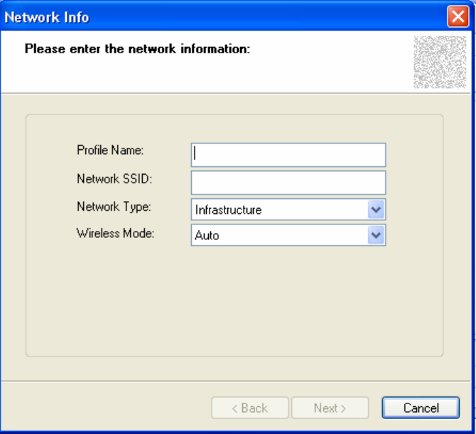
Create a Profile Name, Network SSID Name, and select Network Type & Wireless Mode
to use for this profile. (see Figure 3-3)
Figure 3-3. Network Info
Profile Name: Create a name for your new profile, a useful name is one that is both
descriptive and short.
Network SSID: Define which Network SSID your profile will connect to. Note, SSID
Names are case sensitive, the name must match exactly or your profile won’t associate.
Default is BLANK (associate with any SSID).
Network Type: Users can select from Infrastructure (Default) or Ad-Hoc (Point-to-Point
only access).
Wireless Mode: Auto (Default) will accept traffic from both 1b and 11g Access Points,
while 802.11b Only, will accept only 11b traffic.
Step 2: Establish Security
Security Screen
Select which security mode you wish to use for this profile. (see Figure 3-3)
10
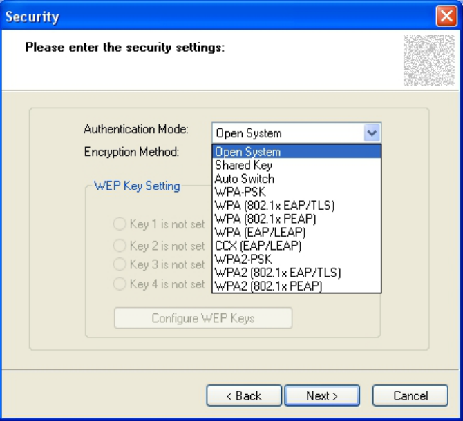
Figure 3-4. Security
Description of items in Figure 3-3 is as follows:
Authentication Mode: Users can select from a range of different security modes. (Default:
Open System).
Encryption Method: Select from the drop down box the desired encryption method.
Shared Key - This is when both the sender and recipient share a secret key.
Auto Switch -
WPA-PSK - A user sets a static key or "Passphrase" as with WEP. But WPA-PSK
automatically changes the keys at a preset time interval, making it much more
difficult for hackers to find and exploit them.
WPA (802.1x EAP/TLS) & WPA (802.1x PEAP) - authentication processes derive
mutually-determined unicast encryption keys. EAP-TLS or PEAP authentication
provides secure wireless networking in a Windows environment.
WPA (EAP/LEAP) – Similar to PEAP, it is a proprietary protocol which was
developed by Cisco.
CCX (EAP/LEAP) – Another Cisco proprietary standard, using Cisco extensions
similar to WPA.
WEP Key Setting
When enabling WEP type encryption, up to 4 WEP Keys may be configured. Click
11
on “Configure WEP Keys” and select either ASCII or HEX based keys.
Click Next > to proceed with Profile Configuration.
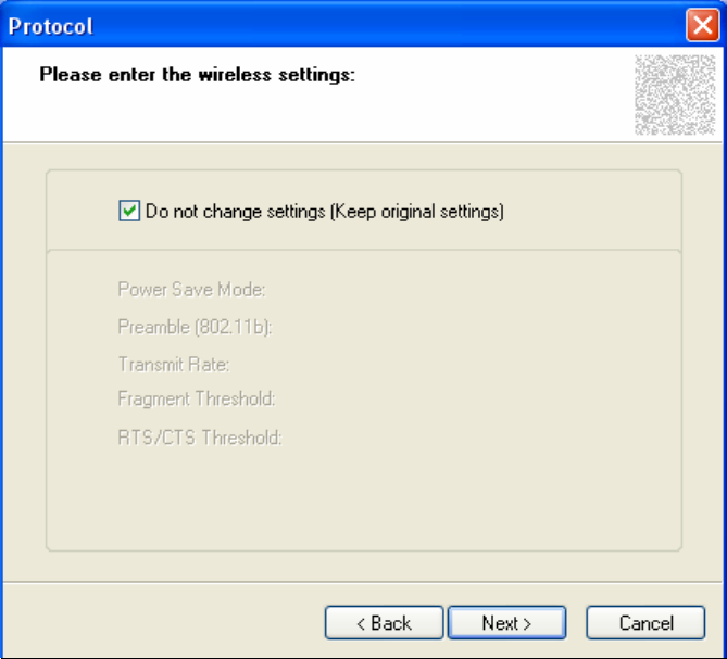
Step 3: Set Wireless Protocol Settings
Wireless Protocol Screen
Figure 3-5 – Protocol Screen
Do Not Change settings (Keep original settings): Leave this checked to keep default
settings in place (recommended) for Power save, Preamble, Transmit Rate, Fragment
Threshold, and RTS/CTS Threshold. Or, if you wish, uncheck this option so as to manually
configure these settings.
Click Next > to Complete New Profile Configuration.
12
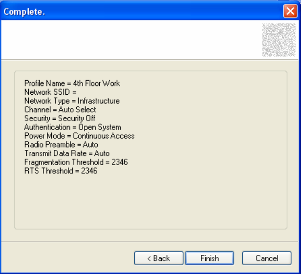
Figure 3-6. New Profile Complete – Summary Screen
The wireless settings for this profile will be summarized on the Complete screen. Click
Finish to complete new profile configuration.
3.2. Network Status Tab
The Network Status tab displays the current association information about the Adapter
connection with a wireless network. (see Figure 3-9)
13
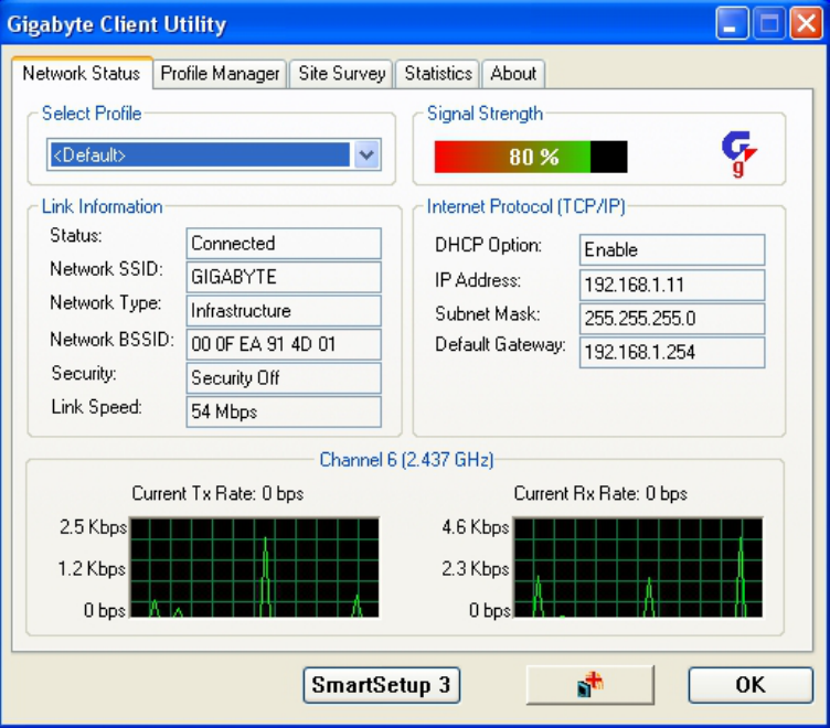
Figure 3-7. Network Status
Description of items in Figure 3-9 is as follows:
Select Profile
Shows the current connection profiles. New profiles can be loaded by simply
selecting them from this drop-down list. Remember, every connection uses a Profile,
even if it’s the <Default> profile.
Signal Strength
The relative strength of the adapter’s association with the Router or Access Point.
Link Information
Link Status: The current connection status, you’ll either be connected or
not-connected.
Network SSID: Also known as Network Name. The network which your adapter
is associated with.
Network Type: Either Infrastructure or Ad-Hoc modes are possible.
Network BSSID: This is the MAC address of your WPMG PCI adapter.
Security: The current security mode being used.
Link Speed: Transmission rate (transferring and receiving) at which data is
transferred between Stations with Adapter and AP. Note that in Ad-Hoc mode,
only 11Mbps is possible.
14
Internet Protocol (TCP/IP)
DHCP Option: Display if DHCP (automatic assignment of client IP address) is
enabled (or disabled) for the current profile.
IP Address: The current IP Address of the WPMG network adapter.
Subnet Mask: The IP Subnet which the WPMG network adapter belongs to.
Default Gateway: The IP Address of the network gateway. Also known as the
IP address of your wireless Router.
Channel Throughput Window
Displays transmit & receive throughput as a function of time.
SmartSetup 3 (Button): Use SmartSetup 3 to instantly create a WPA-PSK encrypted
connection with a new GIGABYTE AP or Wireless Router.
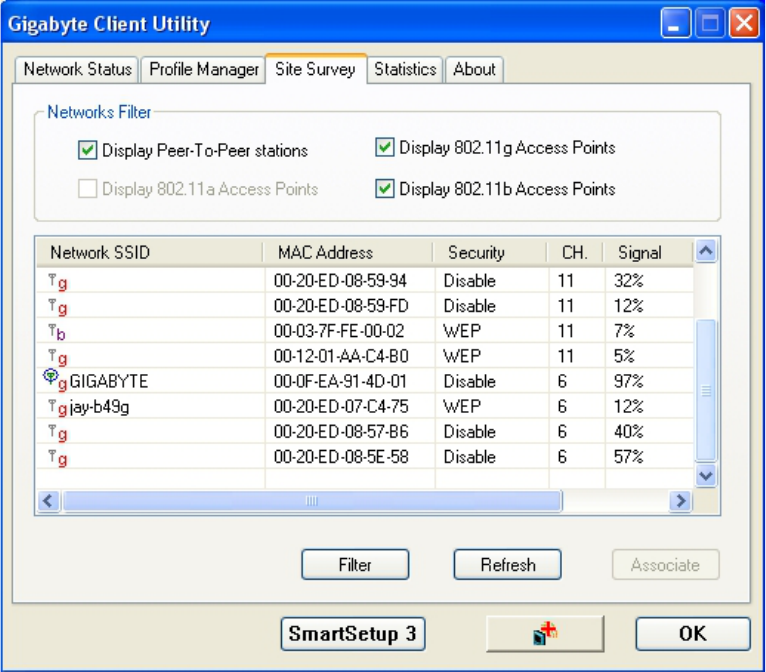
3.3. Site Survey Tab
The Site Survey tab shows you the list of reachable access points and/or peer-to-peer
Stations. Just double click on the SSID that you want to connect or click the Associate
button. (see Figure 3-9)
Figure 3-8. Site Survey
Description of items in Figure 3-10 is as follows:
15
Network Filter
Display Peer-To-Peer stations: When Checked, only displays P2P configured
Access Points.
Display 802.11g Access Points: When checked, only displays 11g Access
Points or Routers (no 11b Access Points will be displayed).
Display 802.11b Access Points: When checked, only displays 11b Access
Points or Routers (no 11g Access Points will be displayed).
Filter (Button): Advanced filters based on SSID Name, MAC Addresses, and wireless
channel.
Refresh (Button): Refresh the list of available access points.
SmartSetup 3 (Button): Use SmartSetup 3 to instantly create a WPA-PSK encrypted
connection with a new GIGABYTE AP or Wireless Router.
16
3.4. Statistics Tab
The Statistics tab shows you the number of packets sent and received by the Adapter
(see Figure 3-11)
Figure 3-9. Statistics
D
escription of items in Figure 3-11 is as follows:
Signal Strength
The relative strength of the adapter’s association with the Router or Access Point.
Transmit
Total Packet: Number of packets transmitted successfully.
Unicast Packet: Number of unicast packets transmitted successfully, excluding
packets transmitted successfully with more than one retry.
Multicast Packet: Number of multicast packets transmitted successfully with
more than one retry.
Single Retries: Number of frames failing to receive ACK after many retries.
Multiple Retries: Representing the number of transmits that required more
than one retry.
Failed count: Representing the transmit excessive retries.
17
RTS Success: Representing the number of successful Ready To Send
RST Failure: Value representing the failed Ready To Send.
ACK Error: Representing the number of failed acknowledgements.
Receive
Total Packet: Number of RTS frames successfully received CTS (Clear To Send)
from AP.
Unicast Packet: Number of RTS frames fail to receive CTS from AP.
Multicast Packet: Number of frames received successfully.
Duplicate Frames: Representing the duplicate frames received.
Received Beacons: The number of beacon packets received by the adapter.
Beacons Lost: The number of beacon packets lost.
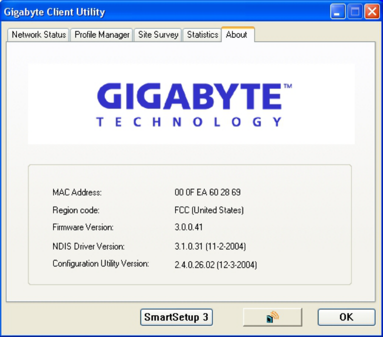
3.5. About Tab
The About tab displays information about current drivers and physical MAC address (see
Figure 3-13).
Figure 3-10. About Tab
18
Region Code (Location) – The region which the current firmware has been localized to.
Firmware Version - Hardware version number of the Adapter’s EEPROM.
MAC Address – The hardware address of the Adapter.
NDIS Driver Version – The Adapter’s network driver interface specification version.
Configuration Utility Version – The GIGABYTE configuration utility version number.
19

Appendix A Troubleshooting
This troubleshooting guide provides answers to some common problems which you may
encounter while installing or using GIGABYTE Wireless Adapters. Contact the GIGABYTE
Wireless Technical Support Team at www.giga-byte.com if you encounter problems not
mentioned in this section.
Problem: Cannot connect to an AP
Advice:
z Make sure the SSID for the Wireless PCI Adapter is the same as the Access
Point.
z Make sure the security settings are the same as that of Access Point. When WEP
or WPA encryption is enabled, check if the WEP or WPA keys for the PCI
Adapter and AP are the same.
z Make sure if the MAC address of the Adapter is added in the AP Authorization
Table.
Problem: Can connect to an AP but cannot connect to the Internet
Advice:
z Make sure the security settings are the same as that of Access Point. When WEP
or WPA encryption is enabled, check if the WEP or WPA keys for the PCI
Adapter and AP are the same.
z Make sure the network configuration (IP address, subnet mask, gateway, and
DNS) of your computer are correct.
z Check the proxy server of the WEB browser is correctly set.
Problem: Poor link quality and signal strength
Advice:
z Keep the Adapter away from microwave ovens and large metal objects to avoid
radio interference.
z Keep the distance between the Adapter and the AP as close as possible.
Please check www.giga-byte.com for more complete and up to date troubleshooting tips.
20

21
Appendix B
Specifications
1. System
Host Interface PCI (low profile) 1 bracket standard size
Operating Voltages 3.3V+/- 5%
2. RF Performance
Frequency Bands 2412-2483.5MHz (subject to local regulations)
Modulation Technology OFDM and DSSS
Modulation Techniques 64QAM, 16QAM, QPSK, BPSK, CCK, DQPSK, DBPSK
Data Rates 54, 48, 36, 24, 18, 12, 9, 11, 6, 5.5, 2 and 1 Mbps, auto fallback
Peak Output Power Targeted at 20dBm @ Nominal Temp Range at antenna connector
Receive sensitivity Targeted at -72dBm @54Mbps; -86dBm@11Mbps
Antenna External antenna with the gain of 2dBi, L type
3.Safety Regulation and Operating Environment
FCC Part 15 (USA) DGT (Taiwan)
EMC certification CE (Europe)
Temperature Range Operating: 0 ~ 55 deg C, Storing: -20 ~ 65 deg C
Humidity 10% ~ 90% Non-condensing
4. Software Support
Driver Windows 98SE/Me/2000/XP
Security WPA; AES; 802.1x; 64/128 bit WEP
Roaming Seamless roaming among 802.11b/g access points.
Management Utility Monitors the network situation.
Software AP support Yes
5. Mechanical
Dimensions 120mm*121mm*20mm (120mm*81mm*20mm)
Weight 58.5(54.5)± 1 g
Packaging Color box with anti-static bag
LED indicator Act and Link
* Subject to change without notice.

Appendix C
Regulatory Information
CE Mark Warning: This is a Class B product. In a domestic environment, this product may cause radio interference, in which case the user may be
required to take adequate measures.
FCC Statement: This equipment has been tested and found to comply with the limits for a Class B digital device, pursuant to Part 15 of the FCC Rules.
These limits are designed to provide reasonable protection against harmful interference in a residential installation. This equipment generates, uses and
can radiate radio frequency energy and, if not installed and used in accordance with the instructions, may cause harmful interference to radio
communications. However, there is no guarantee that interference will not occur in a particular installation. If this equipment does cause harmful
interference to radio or television reception, which can be determined by turning the equipment off and on, the user is encouraged to try to correct the
interference by one of the following measures:
• Reorient or relocate the receiving antenna.
• Increase the separation between the equipment and receiver.
• Connect the equipment into an outlet on a circuit different from that to which the receiver is connected.
• Consult the dealer or an experienced radio/TV technician for help.
FCC Caution: To assure continued compliance, any changes or modifications not expressly approved by the party responsible for compliance could void
the user authority to operate this equipment.
This device complies with Part 15 of the FCC Rules. Operation is subject to the following two conditions: (1) This device may not cause harmful
interference, and (2) this device must accept any interference received, including interference that may cause undesired operation.
IMPORTANT NOTE:
FCC Radiation Exposure Statement:
This equipment complies with FCC radiation exposure limits set forth for an uncontrolled environment. This equipment should be installed and operated
with minimum distance 20cm between the radiator & your body. The antenna(s) used for this transmitter must not be co-located or operating in conjunction
with any other antenna or transmitter.
Europe - Declaration of Conformity
This device is a 2.4 GHz low power RF device intended for home and office use
in EU and EFTA member states. In some EU / EFTA member states some
restrictions may apply. Please contact local spectrum management authorities for
further details before putting this device into operation.
GIGA-BYTE Technology, Inc. declares that the product: Wireless Broadband Router Model Number: GN-B49G is in conformity with and in accordance
with the European Directive of EMC, 89/336 EEC for the following sections:
EN 61000-3-2, EN 61000-3-3, EN 55024, and EN 55022 Disturbances and Immunities
GIGA-BYTE Technology, Inc. also declares the conformity of above mentioned product with the actual required safety standards in accordance with LVD
Directive 73/23 EEC:
EN 60950 Safety
In accordance with R&TTE Directive 1995/5/EC, Part 17: Requirements for Operation in the European Community, GIGA-BYTE Technology, Inc declares
the conformity of the above mentioned products for:
EN 300 328-2 V1.2.1, ETSI EN 300 328-1:V1.3.1, EN 301 489-1, and EN 301 489-17 Technical Requirements for Radio Equipment
Countries of Operation and Conditions of Use in the European Community
The user should run the configuration utility program provided with this product to check the current channel of operation and confirm that the device is
operating in conformance with the spectrum usage rules for European Community countries as described in this section. European standards dictate a
maximum radiated transmit power of 100mW EIRP and a frequency range of 2.400 - 2.4835 Ghz.
Operation using 2.4 GHz Channels in France
2.4 GHz Bande: les canaux 10, 11, 12, 13 (2457, 2462, 2467, et 2472 MHz respectivement) sont complétement libres d'utilisation en France (en utilisation
intérieur). Pour ce qui est des autres canaux, ils peuvent être soumis à autorisation selon le départment. L'utilisation en extérieur est soumis à autorisation
préalable et très restreint. Vous pouvez contacter l'Autorité de Régulation des Télécommunications (http://www.art-telecom.fr) pour de plus amples
renseignements.
Please check ART's web site for latest requirements for use of the 2.4GHz band in France: http://www.art-telecom.fr/eng/index.htm.
When operating in France, this device may be operated under the following conditions:
Indoors only, using any channel in the 2.4465-2.4835 GHz band.
Trademarks: GIGABYTE is a registered trademark of GIGA-BYTE Technology, Inc. Other trademarks or registered trademarks are the property of their
respective manufacturers or owners.
Copyright Statement: No part of this publication or documentation accompanying this Product may be reproduced in any form or by any means or used to
make any derivative such as translation,
transformation, or adaptation without permission from GIGABYTE/GIGA-BYTE Technology, Inc., as stipulated by the United States Copyright Act of 1976.
Contents are subject to change without prior
notice. Copyright© 2004 by GIGA-BYTE Technology, Inc. All rights reserved.
22

Appendix D
Warranty
Limited Warranty Statement (1-Year Warranty)
Thank you for purchasing the GIGABYTE Product. This limited warranty statement will provide you one year warranty starting from the purchase date. Of
which if any defect is occurred due to accidents or any man-made factors, or any unauthorized torn-off or damage to GIGABYTE’s sticker on the product,
GIGABYTE Technology will not provide after-sale services, such as:
• Products are damaged due to any violation of instructions on user manual.
• Hardware is damaged due to inappropriate assembling.
• Products are damaged due to the use of illegal accessory.
• Products are damaged due to parts disassembling without authorization.
• Products are damaged due to exceeding environment limits.
• Products are damaged due to unexpected external force.
• Products are damaged due to nature disasters.
• Products are copies or illegally smuggled goods.
PLEASE RECORD THE FOLLOWING INFORMATION REGARDING YOUR WARRANTY
Name of Customer:
Phone No:
Address:
Email:
Model:
Serial:
Date of Purchase:
Place of Purchase:
From Whom:
Distributor:
Customer Service
GIGA-BYTE TECHNOLOGY CO., LTD.
No.6, Bau Chiang Road, Hsin-Tien,
Taipei Hsien, Taiwan, R.O.C.
Tel: 886-2-8665-2665 Fax:886-2-89124007
http://www.gigabyte.com.tw
Technical Support
E-mail: networksupport@GIGABYTE.com.tw
23
FCC Caution:
1. This device complies with Part 15 of the FCC rules. Operation is subject to the
following two conditions:
(1) This device may not cause harmful interference, and
(2) This device must accept any interference received, including interference
that may cause undesired operation.
2. This device and its antenna(s) must not be co-located or operating in conjunction
with any other antenna or transmitter.
3. Changes or modifications to this unit not expressly approved by the party
responsible for compliance could void the user authority to operate the equipment.