GIGA BYTE TECHNOLOGY GN-WS53HN1 802.11b/g/n Mini Card User Manual 8 IC GN WS53HN1 Manual
GIGA-BYTE TECHNOLOGY CO., LTD. 802.11b/g/n Mini Card 8 IC GN WS53HN1 Manual
UserManual.wiki
>
GIGA BYTE TECHNOLOGY
>
GN WS53HN1 User Manual
Manual
Navigation menu
Upload a User Manual
Namespaces
Wiki Guide
HTML
PDF
Info
Views
User Manual
Discussion / Help
Navigation
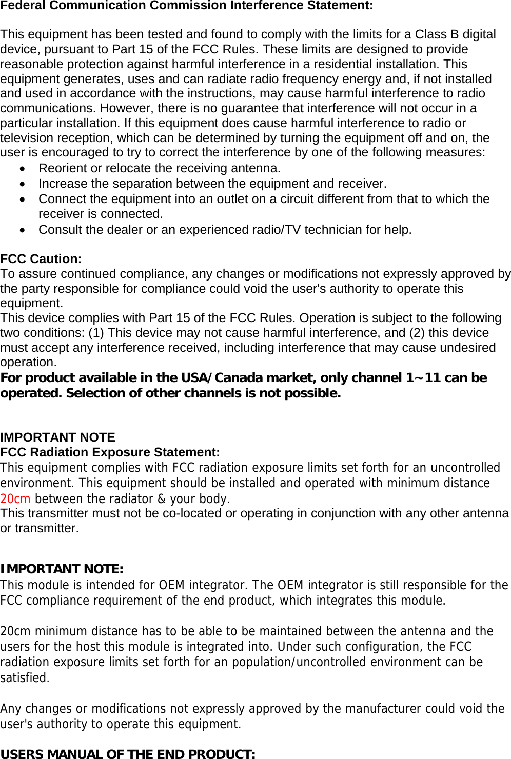
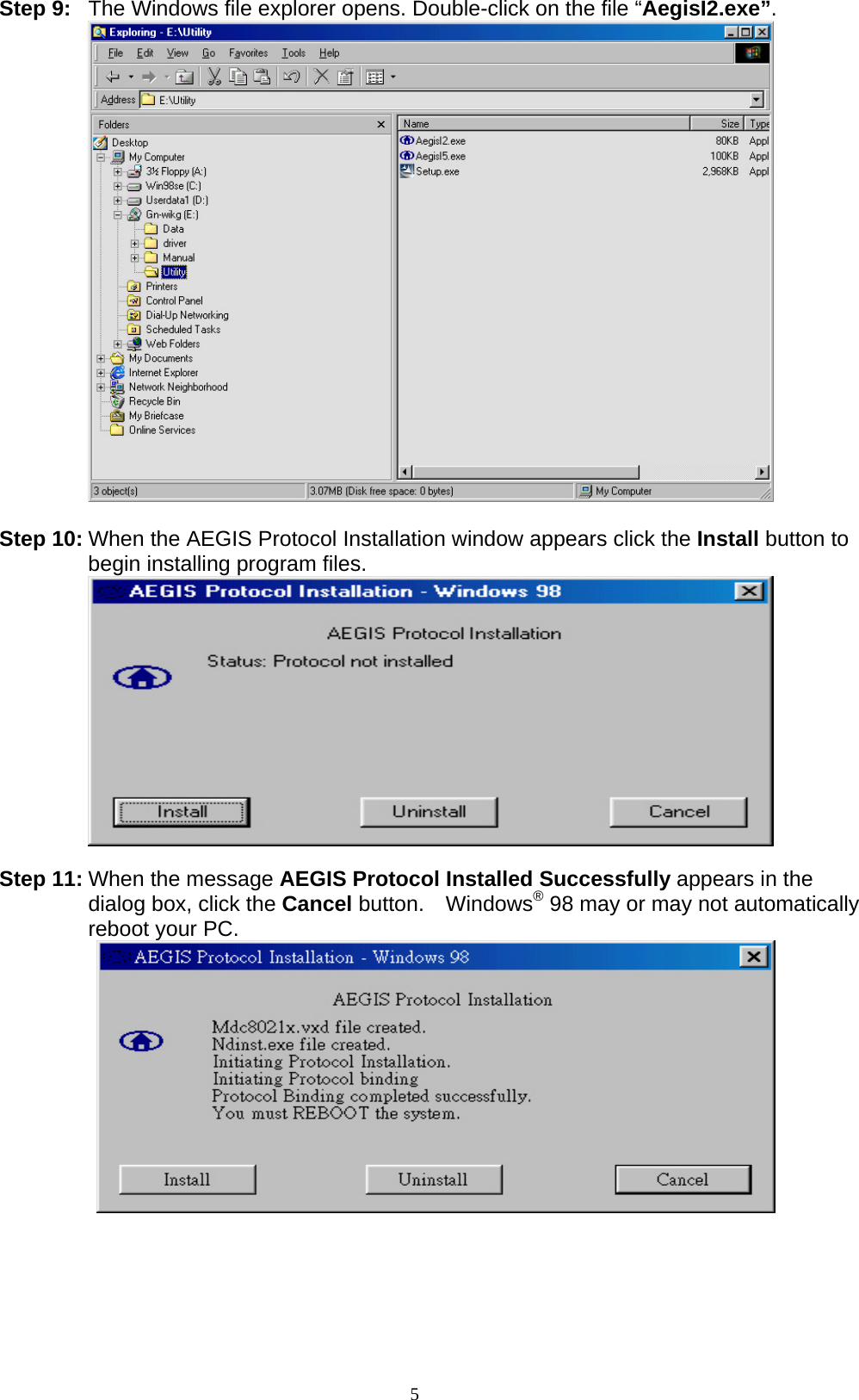
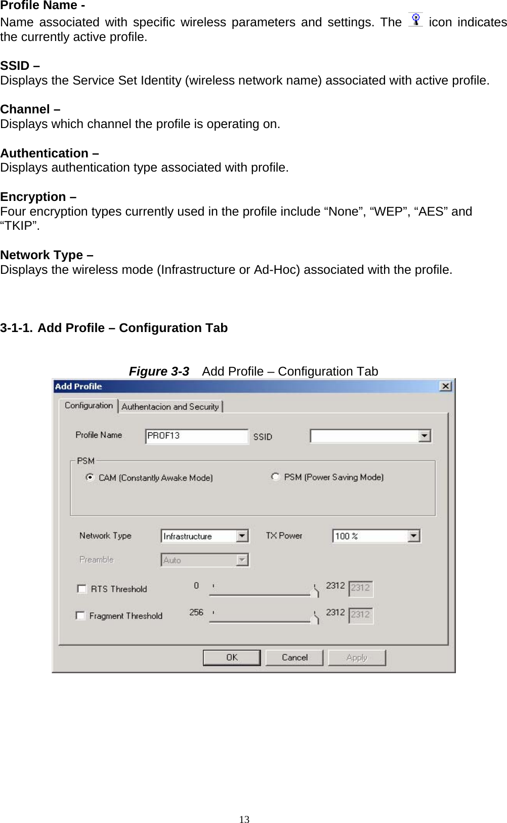
![This Class [*] digital apparatus complies with Canadian ICES-003. Cet appareil numérique de la classe [*] est conforme à la norme NMB-003 du Canada. Statement: This device complies with RSS-210 and IC ES-003 of the Industry Canada Rules. Operation is subject to the following two conditions: (1) This device may not cause harmful interference, and (2) this device must accept any interference received, including interference that may cause undesired operation of this device. Le présent appareil est conforme aux CNR d'Industrie Canada applicables aux appareils radio exempts de licence. L'exploitation est autorisée aux deux conditions suivantes : (1) l'appareil ne doit pas produire de brouillage, et (2) l'utilisateur de l'appareil doit accepter tout brouillage radioélectrique subi, même si le brouillage est susceptible d'en compromettre le fonctionnement. OEM integrator is still responsible for testing their end product for any additional compliance requirements required with this module installed (for example, digital device emissions, PC peripheral requirements, etc.). IMPORTANT NOTE: In the event that these conditions can not be met (for example certain laptop configurations or co-location with another transmitter), then the IC authorization is no longer considered valid and the IC No. can not be used on the final product. In these circumstances, the OEM integrator will be responsible for re-evaluating the end product (including the transmitter) and obtaining a separate IC authorization. End Product Labeling This transmitter module is authorized only for use in device where the antenna may be installed such that 20 cm may be maintained between the antenna and users. The final end product must be labeled in a visible area with the following: “Contains TX IC : 6655A-GNWS53HN”.](https://usermanual.wiki/GIGA-BYTE-TECHNOLOGY/GN-WS53HN1/User-Guide-1478376-Page-4.png)
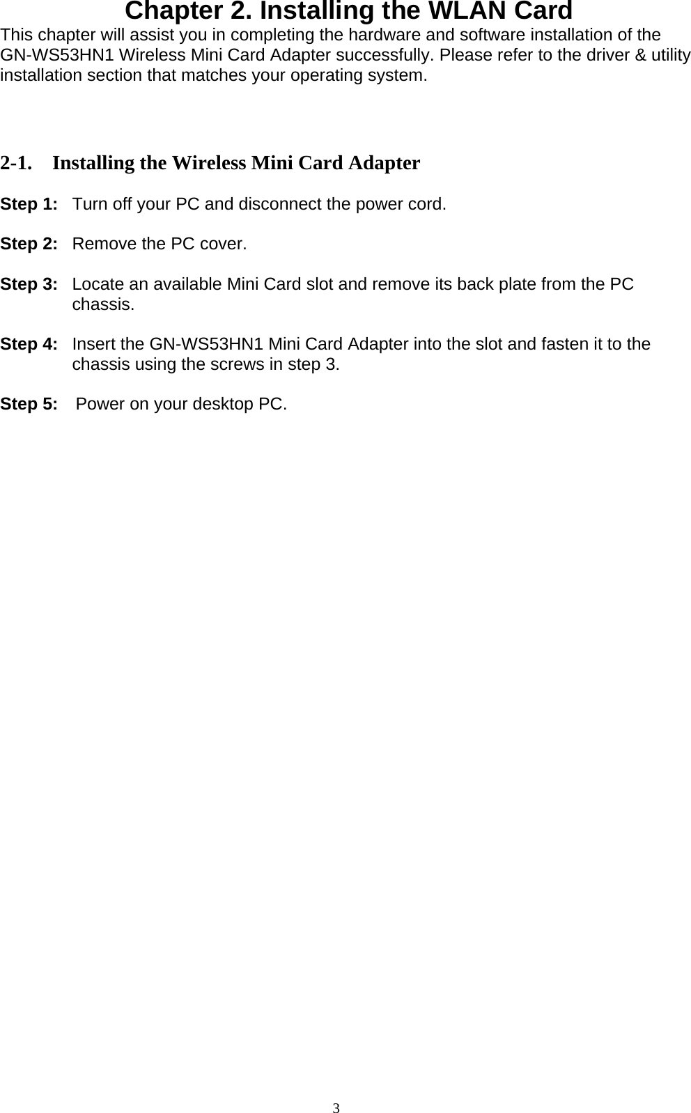
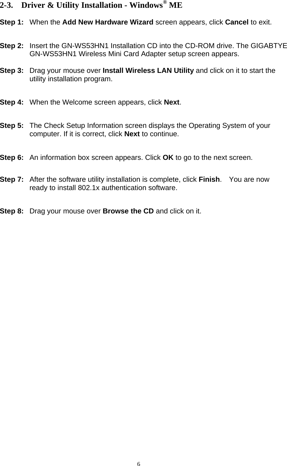
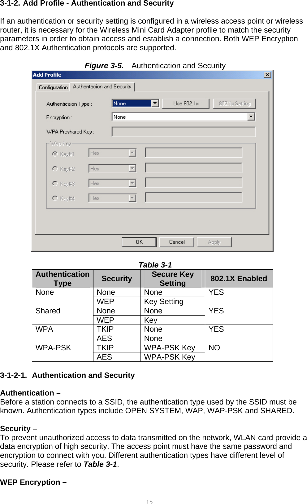
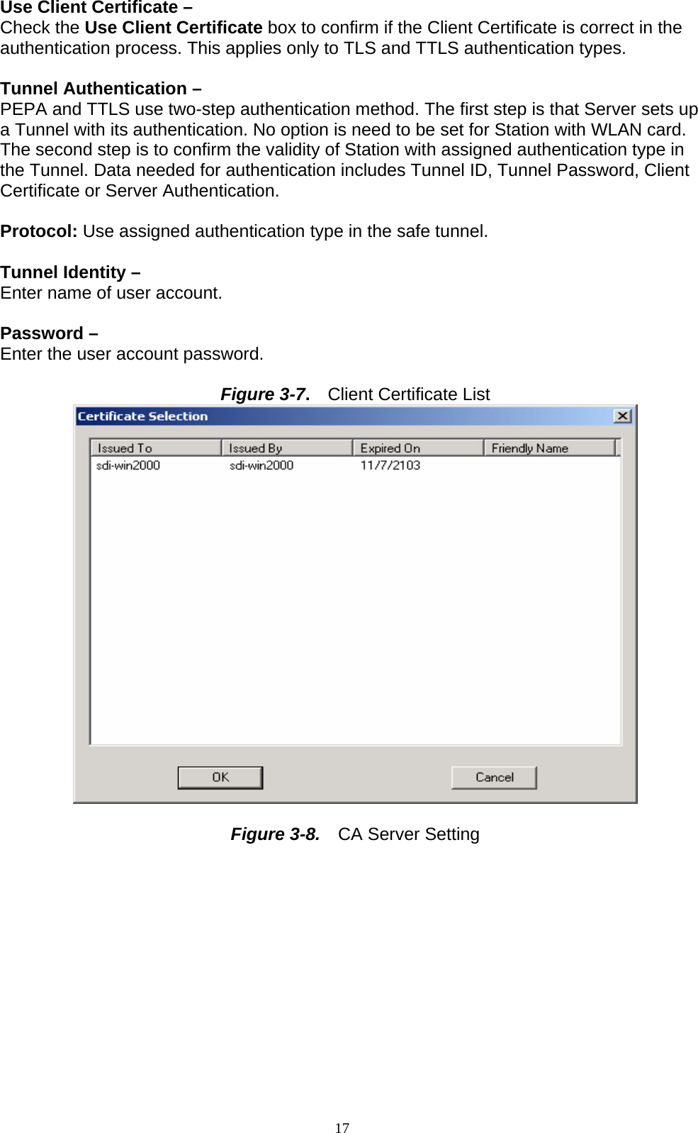
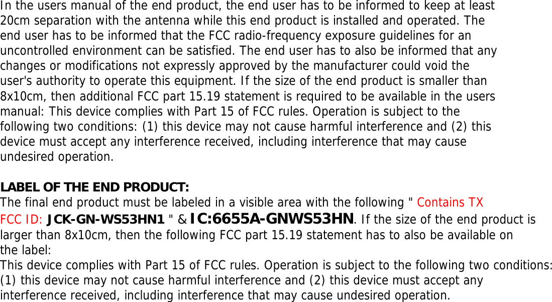
![16 To activate the WEP Encryption, choose WEP Encryption from the drop-down menu in the Encryption field. Then follow instructions below: 1. Select a Key. (You may specify up to 4 Keys) 2. Select data type as either Hex or ASCII. (Hex = hexadecimal) 3. Enter a WEP key. [For 64-bit: 10 hexadecimal digits, 5 ASCII; For128-bit: 26 hexadecimal digits, 13 ASCII] 4. Click OK to save the settings. WPA-PSK Encryption – To activate WPA-PSK (Preshared Key) Encryption using TKIP or AES, choose WPA-PSK from the drop-down menu in the Encryption field. Then follow instructions below: 1. Enter a Preshared Key. [Key may be up to 64 hexadecimal digits or from 8 to 63 ASCII digits in length] 2. Click OK to save these settings. 3-1-2-2. 802.1X Setting To enable 802.1X Authentication, click on the Use 802.1x button (see Figure 3-5 above) and the 802.1X Setting window will open. From the 802.1x Setting window you can configure authentication parameters such as Tunnel Protocol, ID and Password and Client Certificate or Certificate Chain. Figure 3-6 802.1X Setting – Certification Tab Authentication Type – Choose authentication type from the drop-down menu. Authentication types supported include PEAP, TLS/Smart Card, TTLS, LEAP and MD5-Challenge. Identity – Enter the name of the user account. Password – The option to specify a password is only available when LEAP and MD5-Challenge are selected as the authentication types.](https://usermanual.wiki/GIGA-BYTE-TECHNOLOGY/GN-WS53HN1/User-Guide-1478376-Page-21.png)