GIGA TMS TR320 TIME RECORDER User Manual TR320UserManual TM951303
GIGA-TMS INC. TIME RECORDER TR320UserManual TM951303
GIGA TMS >
User Manual
GIGATMS
TR320 Time Recorder
User’s Manual
2012/6/4
2
1. Contents
1.
CONTENTS ......................................................................................................................................................................... 2
2.
CHANGE HISTORY .............................................................................................................................................................. 4
3.
ABOUT THIS MANUAL ....................................................................................................................................................... 5
4.
HARDWARE MANUAL ........................................................................................................................................................ 6
4.1
I
NTRODUCTION
..................................................................................................................................................................... 8
4.2
E
XTERNAL
A
PPEARANCE
......................................................................................................................................................... 8
4.3
H
ARDWARE
S
PECIFICATION
................................................................................................................................................... 10
4.4
I
NSTALLATION
..................................................................................................................................................................... 11
4.5
P
OWERING
U
P FOR THE
F
IRST
T
IME
........................................................................................................................................ 11
4.6
S
YSTEM STATUS DISPLAY
....................................................................................................................................................... 13
4.7
RFID
C
ARD READING AND DISPLAY
......................................................................................................................................... 14
4.8
R
EADING
M
ASTER
C
ARD
...................................................................................................................................................... 15
4.9
S
YSTEM
S
ETTING
................................................................................................................................................................. 15
4.10
D
OWNLOADING
A
TTENDANT DATA
.......................................................................................................................................... 19
5.
SOFTWARE MANUAL ....................................................................................................................................................... 20
5.1
S
UBSTANTIVE
E
XPLANATION
.................................................................................................................................................. 21
5.2
I
NSTALL
&
U
NINSTALL
.......................................................................................................................................................... 22
5.2.1
System requirements ................................................................................................................................................. 22
5.2.2
Products specification ............................................................................................................................................... 22
5.2.3
Install Time Recorder Utility (TRU) ............................................................................................................................ 22
5.2.4
Install TR320 Manager .............................................................................................................................................. 24
5.2.5
Uninstall Time Recorder Utility (TRU)........................................................................................................................ 25
5.2.6
Uninstall TR320 Manager ......................................................................................................................................... 26
5.3
T
IME
R
ECORDER
U
TILITY
...................................................................................................................................................... 27
5.3.1
Setup Connections and Password .............................................................................................................................. 27
5.3.1.1
Acquire IP address .............................................................................................................................................................. 27
5.3.1.2
Setup Connection in TRU .................................................................................................................................................... 27
5.3.2
Setup Properties ........................................................................................................................................................ 29
5.3.2.1
Setup Login password ......................................................................................................................................................... 29
5.3.3
Downloading Time Data ........................................................................................................................................... 31
5.3.4
Language Editor ........................................................................................................................................................ 33
5.3.4.1
Adding New Language ........................................................................................................................................................ 34
5.3.4.2
Editing String Table ............................................................................................................................................................. 34
5.3.4.3
Applying Language .............................................................................................................................................................. 36

3
5.3.4.4
Notes................................................................................................................................................................................... 36
5.3.5
Maintain Database .................................................................................................................................................... 36
5.3.5.1
Backup Database ................................................................................................................................................................ 37
5.3.5.2
Restore Database ................................................................................................................................................................ 37
5.3.5.3
Compact Database .............................................................................................................................................................. 37
5.3.6
Loading TR320 Manager Software ............................................................................................................................ 37
5.4
TR320
M
ANAGER
.............................................................................................................................................................. 38
5.4.1
The first execution ..................................................................................................................................................... 38
5.4.1.1
Check login password ......................................................................................................................................................... 38
5.4.2
Create a tree structure .............................................................................................................................................. 39
5.4.2.1
Company ............................................................................................................................................................................. 39
5.4.2.2
Department ........................................................................................................................................................................ 39
5.4.2.3
Title ..................................................................................................................................................................................... 39
5.4.2.4
User (Employees) ................................................................................................................................................................ 40
5.4.3
Information ............................................................................................................................................................... 41
5.4.3.1
Create message template (*.mt) file ................................................................................................................................... 41
5.4.3.2
Bind to database ................................................................................................................................................................. 41
5.4.3.3
Assign to users (Employees)................................................................................................................................................ 42
5.4.3.4
Message .............................................................................................................................................................................. 45
5.4.3.5
Update to machine ............................................................................................................................................................. 46
5.4.3.6
Delete message................................................................................................................................................................... 47
5.4.3.7
Change machine image ....................................................................................................................................................... 49
5.4.3.8
Search function ................................................................................................................................................................... 49
5.4.3.9
Backup ................................................................................................................................................................................ 50
5.5
A
PPENDIX
-A ...................................................................................................................................................................... 51
5.5.1
A-1 Message Tool .................................................................................................................................................. 51
5.5.1.1
Overview of Message Tool Window .................................................................................................................................... 51
5.5.1.2
Template Components ........................................................................................................................................................ 53
5.5.1.3
Drawing Shapes and Lines................................................................................................................................................... 53
5.5.1.4
Modifying Shapes and Lines ............................................................................................................................................... 53
5.5.1.5
Deleting Shapes and Lines .................................................................................................................................................. 54
5.5.1.6
Typing Text .......................................................................................................................................................................... 54
5.5.1.7
Modifying Text .................................................................................................................................................................... 54
5.5.1.8
Deleting Text ....................................................................................................................................................................... 55
5.5.1.9
Inserting Image ................................................................................................................................................................... 55
5.5.1.10
Changing Image .................................................................................................................................................................. 55
5.5.1.11
Deleting Image .................................................................................................................................................................... 55
5.5.1.12
Saving Message Template ................................................................................................................................................... 55
5.5.1.13
Exporting Message Template .............................................................................................................................................. 56

4
2. Change History
Release Date Version Description
8/28/2011 0.8.0 First draft
5/23/2012 0.9.0 Include Hardware Manual
6/4/2012 1.0.0 Add more FCC Warning and Compliance Statements

5
3. About This Manual
This manual, the TR320 Time Recorder User’sManual, provides information about installing and using
TR320 Time Recorder. Two parts are consisted in this manual:
Hardware Manual Describes the hardware of TR320 Time Recorder.
Software Manual Describes available PC software.
6
4. Hardware Manual
This part of documentation describes the specification and operations of TR320 Time Recorder.

7
FCC Warning and Compliance Statement:
FCC Warning:
Changes or modifications which are not expressly approved by the GIGA-TMS Inc. could
void the user's authority to operate the equipment.”
FCC Part 15 Regulatory Compliance:
This equipment complies with Part 15 of the FCC rules, and operation is subject to the following two
conditions:
(1) This device may not cause harmful interference.
(2) This device must accept any interference received, including interference that may cause undesired
operation.
This equipment has been tested and found to comply with the limits for a Class B digital device, pursuant to
part 15 of the FCC Rules. These limits are designed to provide reasonable protection against harmful
interference in a residential installation. This equipment generates uses and can radiate radio frequency
energy and, if not installed and used in accordance with the instructions, may cause harmful interference to
radio communications. However, there is no guarantee that interference will not occur in a particular
installation. If this equipment does cause harmful interference to radio or television reception, which can be
determined by turning the equipment off and on, the user is encouraged to try to correct the interference by
one or more of the following measures:
- Reorient or relocate the receiving antenna.
- Increase the separation between the equipment and receiver.
- Connect the equipment into an outlet on a circuit different from that to which the receiver is connected.
- Consult the dealer or an experienced radio/TV technician for help.
8
4.1 Introduction
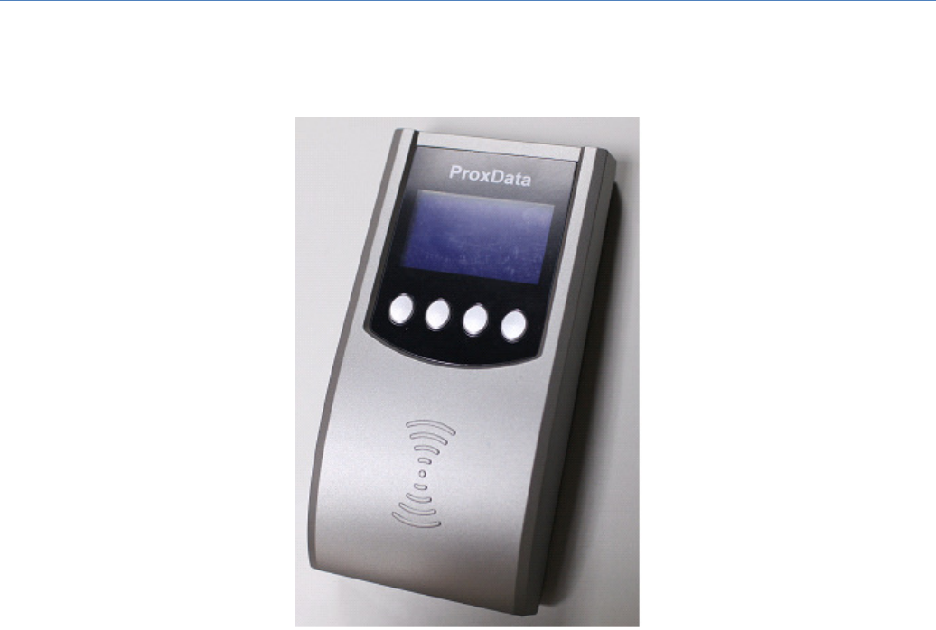
TR320 is a time recorder to provide recording of attendance using the RFID technology. With its
graphic display, this time recorder provides not only access control based on built in white list records
but also the message display for each personal identification. Besides, the administrator can configure
each white list personal ID with its associate name, department and title by using the specific TR320
Utility developed by GIGA-TMS; therefore, each white list user can see his/her personal information
while punching his or her RFID card. In addition, user can replace system’s icons and Logo with their
preferred one(s) by using this TR320 Utility.
4.2 External Appearance
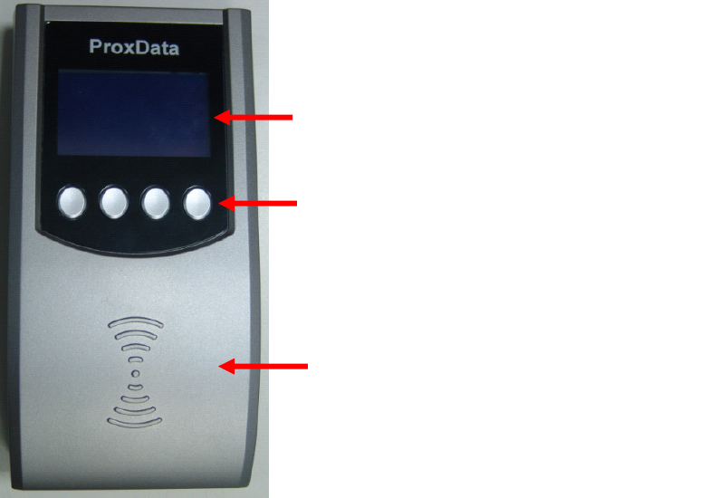
128* 64 Graphic Monochrome LCD Display
Event keys: (Left to Right)
IN, OUT, BREAK IN, BREAK OUT
RFID card reading area
9
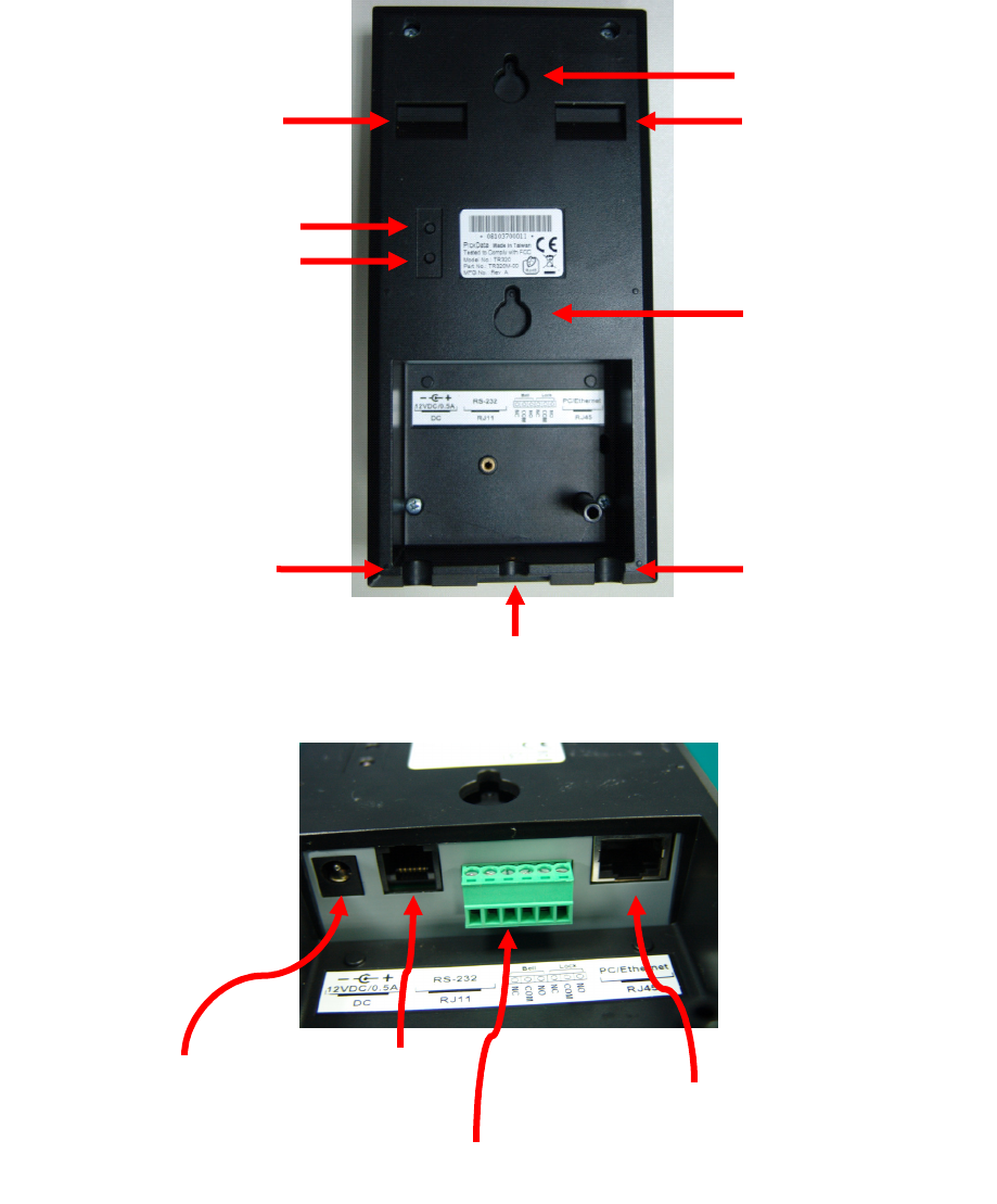
Wall bracket notch
Wall bracket notch
Factory reset buttom
System reset buttom
Ethernet line slot
Power & Relay I/O line slot
Wall bracket screw hole
RJ45 Ethernet Connector
Bell and Door Lock Relay
Diagnostic Port
Power Adaptor Jacket
Wall suspend notch
Wall suspend notch

10
4.3 Hardware Specification
Display 128x64 Graphic Monochrome, blue backlight
RFID card type ISO/IEC 1443A/MiFare
Ethernet port 10 Base-T/100 Base-TX, 802.3 compliance
Bell and Door Relay AC 250V/10A or AC 125V/15A, DC 12A/28V
Environment Operating: 0 ~ 55℃, Storage: -10 ~ 55℃, 90% R.H.
Power Consumption DC: 12V/500mA
Internal memory 10000 attendant records,1000 white list records, 1000
message records

11
4.4 Installation
Please refer to the packing and installation sheet in the gift box to install TR320 on the wall.
4.5 Powering Up for the First Time
Once TR320 is powered up, it shows product name and company logo, and then acquires IP
address from network.
Display Logo Screen
This product and Logo screen can be replaced by TR320 utility.
Information Screen
Get IP successfully:
Fail to get IP address:
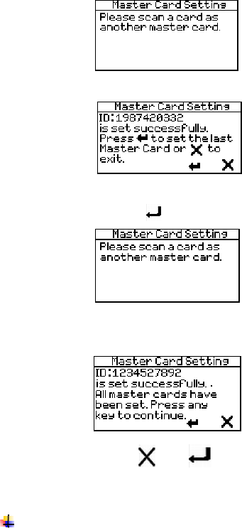
If it’s the first time to power up TR320, you have to set master card for administrator by following
the procedures below.
Master Card Enrollment Screen
It’s required to set a least one master card by following the steps below.
1. Entry screen for Master Card setting:
2. After sweeping a RFID card:
3. Press key to set the second master card.
12
4. Sweep another RFID card as the second master card.
5. Press key to set the third master card.
6. Sweep one more RFID card as the third master card.
7. Press or key to finish Master Card setting and go to normal working screen.
If TR320 has been set at least one master card, it will go to normal working screen directly after
powering up the system.

13
4.6 System status display
Normal working state:
When the time recorder is ready to read a RFID card, it shows its current date and time, week day,
Ethernet link, attendant record memory status and event icons as the screen below. The shift number
will be displayed only if it is set from ‘01’ to ‘99’.
Network Status Icons:
: Ethernet link works normally and has got IP address successfully.
: Ethernet link is disconnected.
: Ethernet linked is connected but not able to get IP address.
Each of the icons is a 17(width)*16(height) BMP file and it can be replaced by TR320 Utility.
RFID card reading memory occupation status icons:
: Memory occupation is below 1/3 of the total space.
: Memory occupation has reached 1/3 and below 2/3 of the total space.
: Memory occupation has reach 2/3 of the total space but not yet full.
: Memory occupation is full.
Each of the icons is a 13(width)*8(height) BMP file and it can be replaced by TR320 Utility.
Shift Icon:
: The shift number will be shown only when the shift is set except 00, .i.e. from 01 to 99.
Card reading logging state icons:
: IN
: OUT
: BREAK IN
: BREAK OUT
When the icon is highlighted, the carding reading will be recorded with the selected logging state. Each
of the icons is a 24(width)*16(height) BMP file and it can be replaced by TR320 Utility.
14
4.7 RFID Card reading and display
RFID Card Reading
When TR320 is at normal working state and a MiFare 13.5M RFID card is read, this time recorder may
show the message according to the following status.
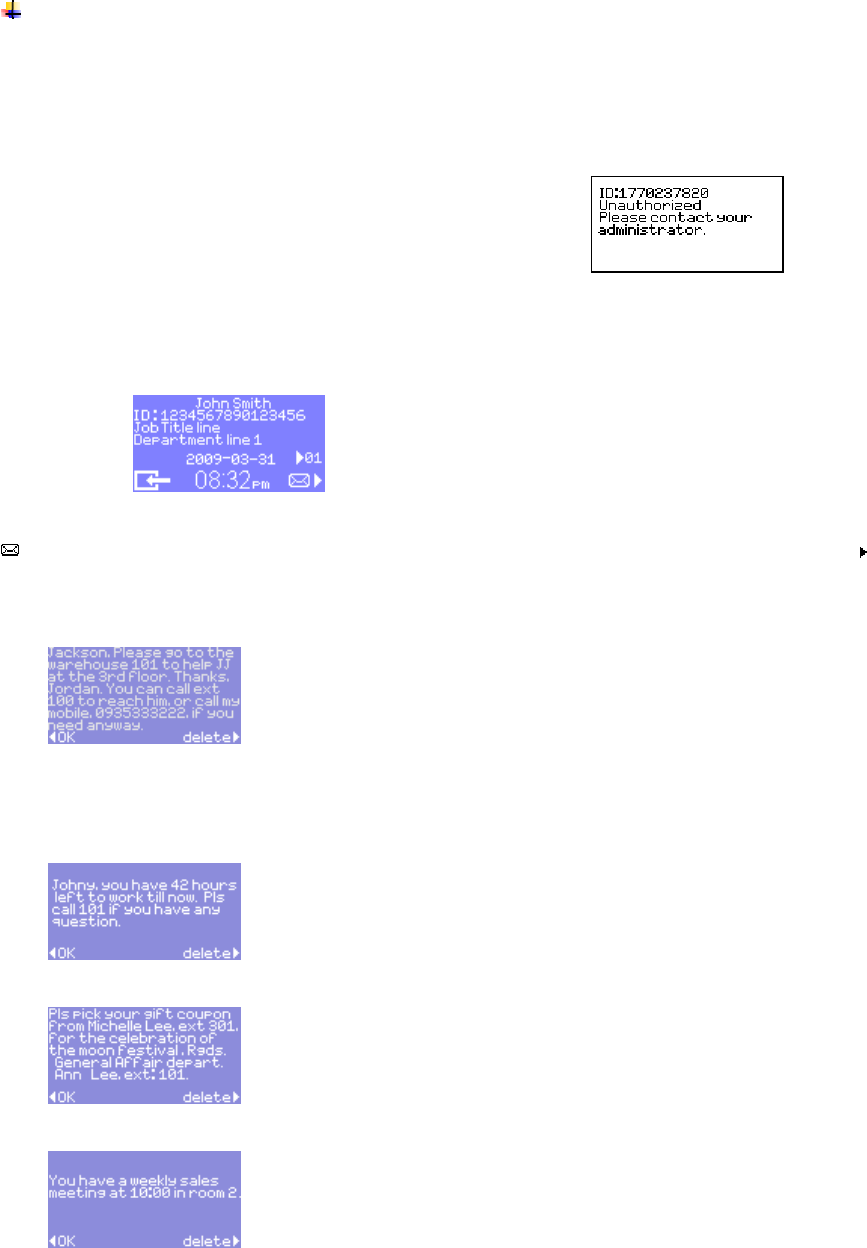
1. When the RFID card is not one of the white list records, a warning tone will be heard and the
warning message will be displayed like below.
2. When the RFID card is a white list record and the relative name, job title and department has been
configured in advance, and there is a message for this ID. TR320 will show this ID’s relative
message along with a message icon like below.
: This mailbox icon indicates that this user ID has a message left and user can press to view
message. Here are some example message applications below.
Job and working place assignment:
Remaining working hour display:
If the employees are paid by hour, the message below shows the remaining working hour via the
calculation of working hour from PC side application.
General notice publication:
Meeting notice:
[Message operation]
Press key below “delete” to delete message shown on the display.
15
Press key below “OK” to exit to normal working state.
System time out: If there is no key pressed, system will go back to normal working state after a
configurable delay time.
Card reading during message display: If there is another card read, system will show message
for this RFID card as the description above.
Message expiration: If a message is expired, this message will be deleted automatically by the
time recorder.
There is at most one message for each user ID before it is deleted.
3.
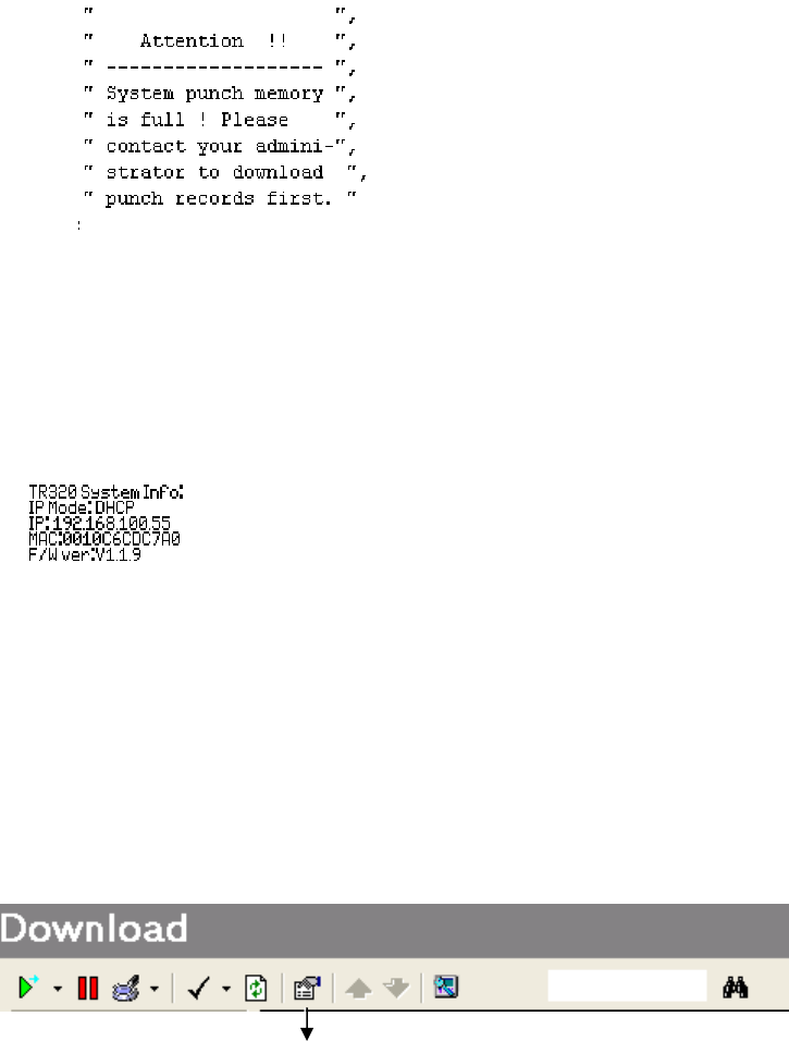
When the RFID card reading memory is full, TR320 will show the warning message below. In such
case, the administrator has to download records; otherwise, TR320 will not open the door.
4.8 Reading Master Card
Master card can now be used to provide the following basic system information:
IP acquisition modes, IP and MAC address, and Firmware Version.
4.9 System Setting
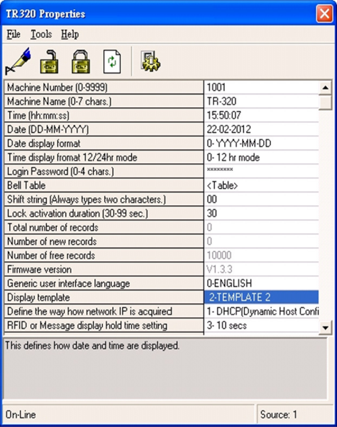
TR320 has to be configured via the specific TR320 Utility developed by GIGA-TMS Inc. Start up TRU
Utility and double click the property icon to enter the TR320 login password and bring up TR320 property
setting screen as below.
Property icon
16
17

18
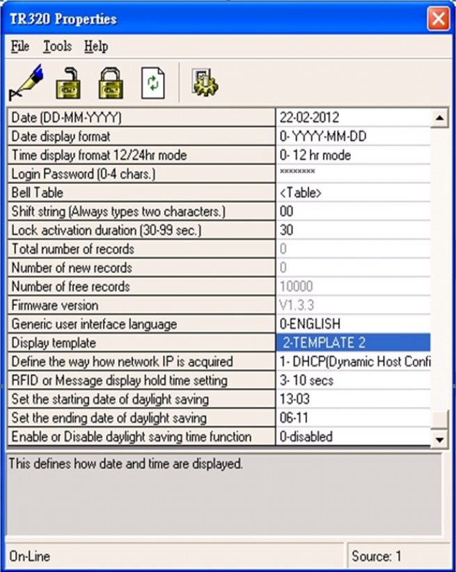
Item name Definition Default
Machine number This item is part of the attendant record
sent by TR320, and it is used to identify
which TR320 is sending this attendant
record.
1001
Machine name Name of a TR320 device TR-320
Time Current Time of TR320 N/A
Date Current date of TR320 N/A
Date display format yyyy-mm-date or mm-date-yyyy yyyy-mm-date
Time display format 12/24hr mode 12 or 24 hour display mode. 12
Login Password TR320 Property Login password.
(max 4 digits)
1234
Bell Table There are 32 bell settings records, each
which includes the setting elements of
action week, action time and duration.
Bell relay will activate according to the
setting records.
none
Shift string There are always two digits from “01” to
“99” to display shift. “00” is a default
shift used for not to show shift.
00
Lock activation duration Activation duration of door lock. 30 sec
Total number of records Current total white list card reading
records. This field is read only.
N/A
Number of new records New records not yet downloaded. N/A
Number of free records Records available to be used for white list
card reading.
N/A
Firmware version TR320 firmware version N/A
Generic user interface language Future usage for multiple language
application. Only English is available for
TR320 now.
English
Display template Normal mode display template setting. Template 2
Define the way how network IP is acquired IP acquisition: DHCP or STATIC IP DHCP
RFID or Message display hold time setting Card reading or message display delay
time.
5 sec
Set the starting date of daylight saving Daylight setting starting date
Set the ending date of daylight saving Daylight setting ending date
Enable or Disable daylight saving time function Enable or Disable daylight time Disable

19
4.10 Downloading Attendant data
The TR320 saves the attendance data onto its internal flash memory using a so-called delimited text format.
With delimited text format, fields within a record are separated by a TAB character (tabulation, ASCII= 09
Hex) while records are separated from each other by CR (Carriage Return, ASCII= OD Hex) and LF (Line
Feed, ASCII= 0A Hex) characters.
Each TR4050’s record consists of the following fields:
Field Length Format
Event 1 “1”, “2”, “3”, “4”
Date 10 “DD-MM-YYYY”
Time 8 “hh:mm:ss”
ID-code 10 “’XX…X”, apostrophe is added to make sure that
this field is treated as a string by applications like
Microsoft Excel.
Shift 2 “SS”, can be in the range from 01 to 99.
Machine No 4 “NNNN” can be in the range from 0000 to 9999.

20
5. Software Manual
This part of the document describes all PC software supplied by GIGA-TMS.
Two software packages are available:
Time Recorder Utility This software is able to configure device connections, properties and
downloading time data etc.
TR320 Manager This software is able to establish user information and messages.

21
5.1 Substantive Explanation
◆ IP Address : Internet Protocol Address
◆ Information : The image on TR320 while user induce his tag
◆ Message : The image on TR320 in check message function
◆ White list : All users in database of TR320 Manager, and this list will sync to TR320 after Update
function
◆ Message template : Create a template in Message Tool. The template allow us to fill different data
to the text field for different user

22
5.2 Install & Uninstall
5.2.1 System requirements
Minimum
Requirements
Recommended
Internet
Connections
TCP/IP LAN
(With DHPC)
TCP/IP LAN
(With DHPC)
Operation System
XP,Vista,Windows7 XP,Vista,Windows7
Computer
processor
800MHz Pentium III
1.5GHz(XP),2GHz(Vista,Windows7)
or better
Computer Memory
512MB 1GB
Screen Resolution
1024x768 pixels 1024x768 pixels or better
5.2.2 Products specification
.1000 white list occupations
.Leave message to given user(s)
.Entrance guard
.Attendance record
.Manage user(s)
.Create unique information for every user
.Search functions for database
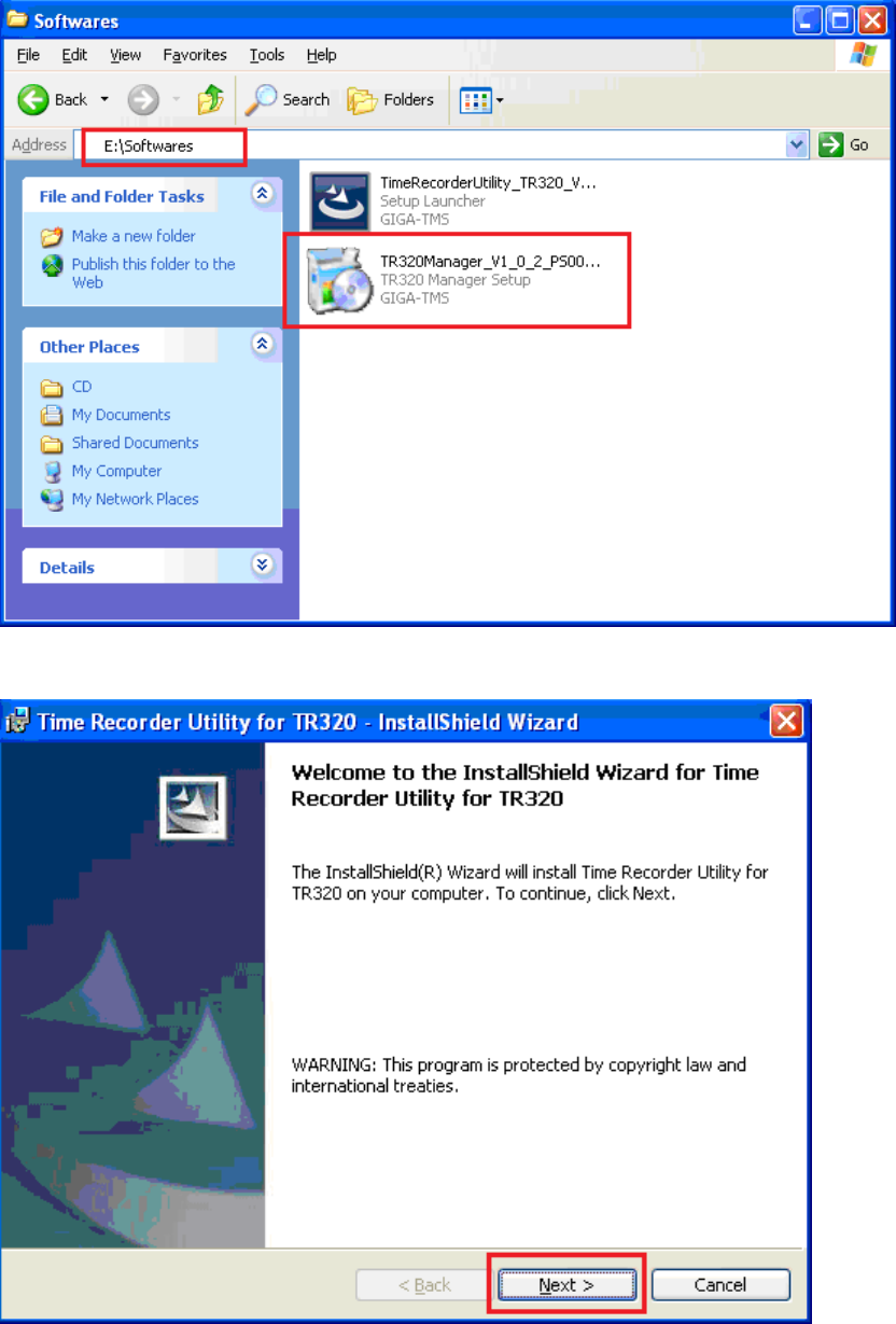
5.2.3 Install Time Recorder Utility (TRU)
Browse PROMAG
GG
G.
..
.ProxData
ProxDataProxData
ProxData
CD
The directory \\software
23
Execute TR320Manager_V1_0_X_PS00138.exe
Click Next to install Time Recorder Utility (TRU)
24
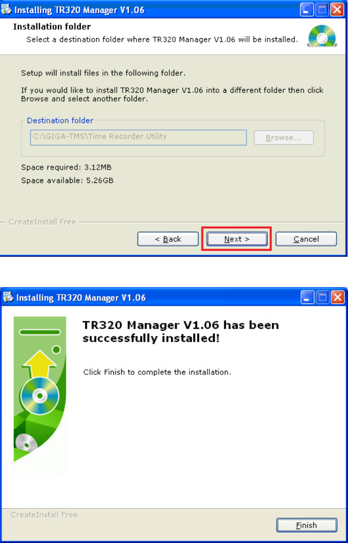
5.2.4 Install TR320 Manager
TR320Manager Installation will pop out after the installation of TRU
Click Next to install TR320Manager
Finish the installation
25
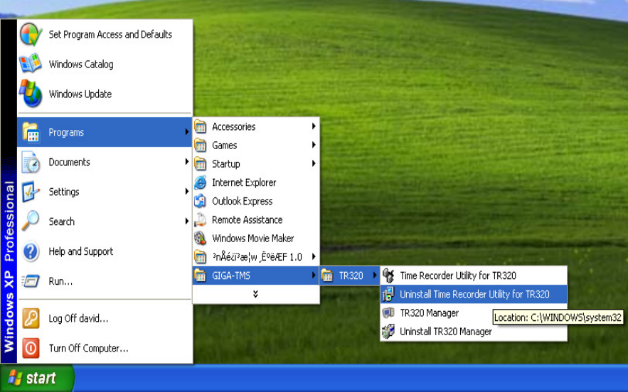
5.2.5 Uninstall Time Recorder Utility (TRU)
In Programs->GIGATMS->TR320
Execute Uninstall Time Recorder Utility for TR320 to uninstall TRU
26
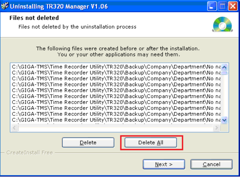
5.2.6 Uninstall TR320 Manager
In Programs->GIGATMS->Uninstall TR320 Manager
Execute Uninstall TR320 Manager
You have to select Delete All option here to clear all folders
27
5.3 Time Recorder Utility
5.3.1 Setup Connections and Password
5.3.1.1 Acquire IP address
※
※※
※Notes
NotesNotes
Notes
.
..
.Confirm TR320 wa
Confirm TR320 waConfirm TR320 wa
Confirm TR320 was connected to your Local Area N
s connected to your Local Area Ns connected to your Local Area N
s connected to your Local Area Network (LAN)
etwork (LAN)etwork (LAN)
etwork (LAN)
.
..
.Confirm
Confirm Confirm
Confirm router
routerrouter
router
with DHCP (Dynamic Host Configuration Protocol)
with DHCP (Dynamic Host Configuration Protocol)with DHCP (Dynamic Host Configuration Protocol)
with DHCP (Dynamic Host Configuration Protocol)
function
functionfunction
function
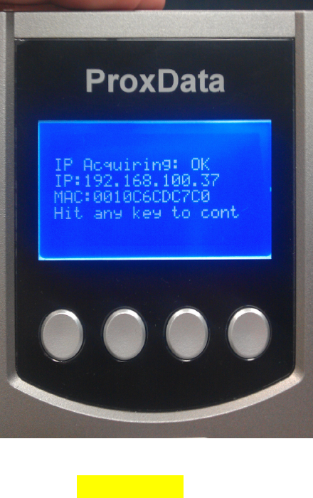
Plug in the power to TR320
The IP address acquired
Address is 192.168.100.37
5.3.1.2 Setup Connection in TRU
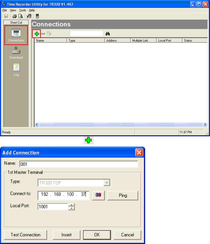
Execute Time Recorder Utility for TR320
28
Select the Connections and click to add a new machine
Use Ping and Test Connection to check the communication is correct
If the communication is correct, press OK to create this connection on TRU
29
5.3.2 Setup Properties
5.3.2.1 Setup Login password
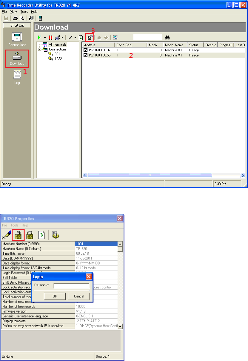
Switch to Download page, select a connection and click properties as picture
30
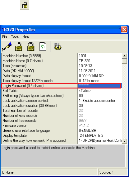
Click to login the current machine
Enter the default password is “1234”
Double click on Login password and enter new password
※ Please remember this password, TR320 need this password while login.
31
5.3.3 Downloading Time Data
While users punch the time data, the Tag ID will be stored in the internal memory of terminal, associated
with the date, time, event id and shift number.
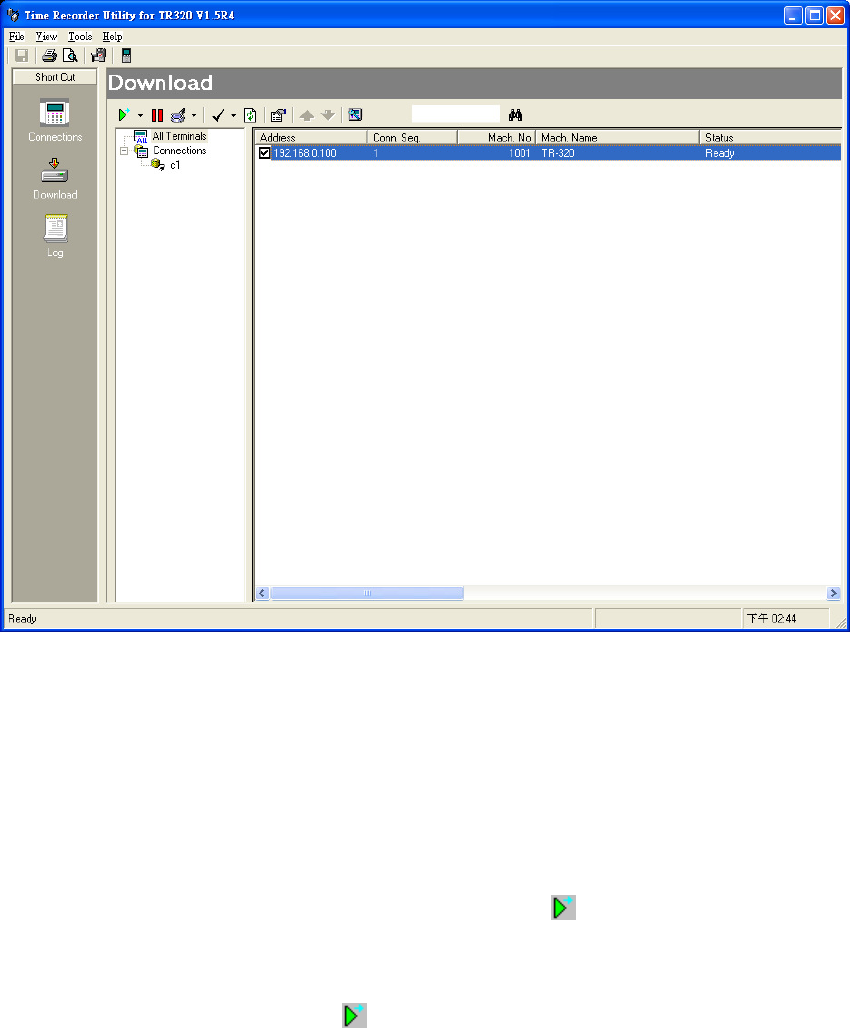
After setting up the connections, all the terminals will be displayed in the [Download] inspection.
In this inspection, you can get a brief view of the properties of connected terminals, such as the machine
number, name etc. If you want get more detail information, just double-click the list item, a properties
window will pop up, which shows all the information of the selected terminal. Please keep in mind, some of
the properties need to login first prior to modify.
TRU provides two ways to download the time data: Download at once and Scheduling, which are detailed as
below.
Download at once:
Select the checkbox on the list view, and then click on the toolbar. All the time data of selected
(checked) terminals will be downloaded and saved to the specified path.
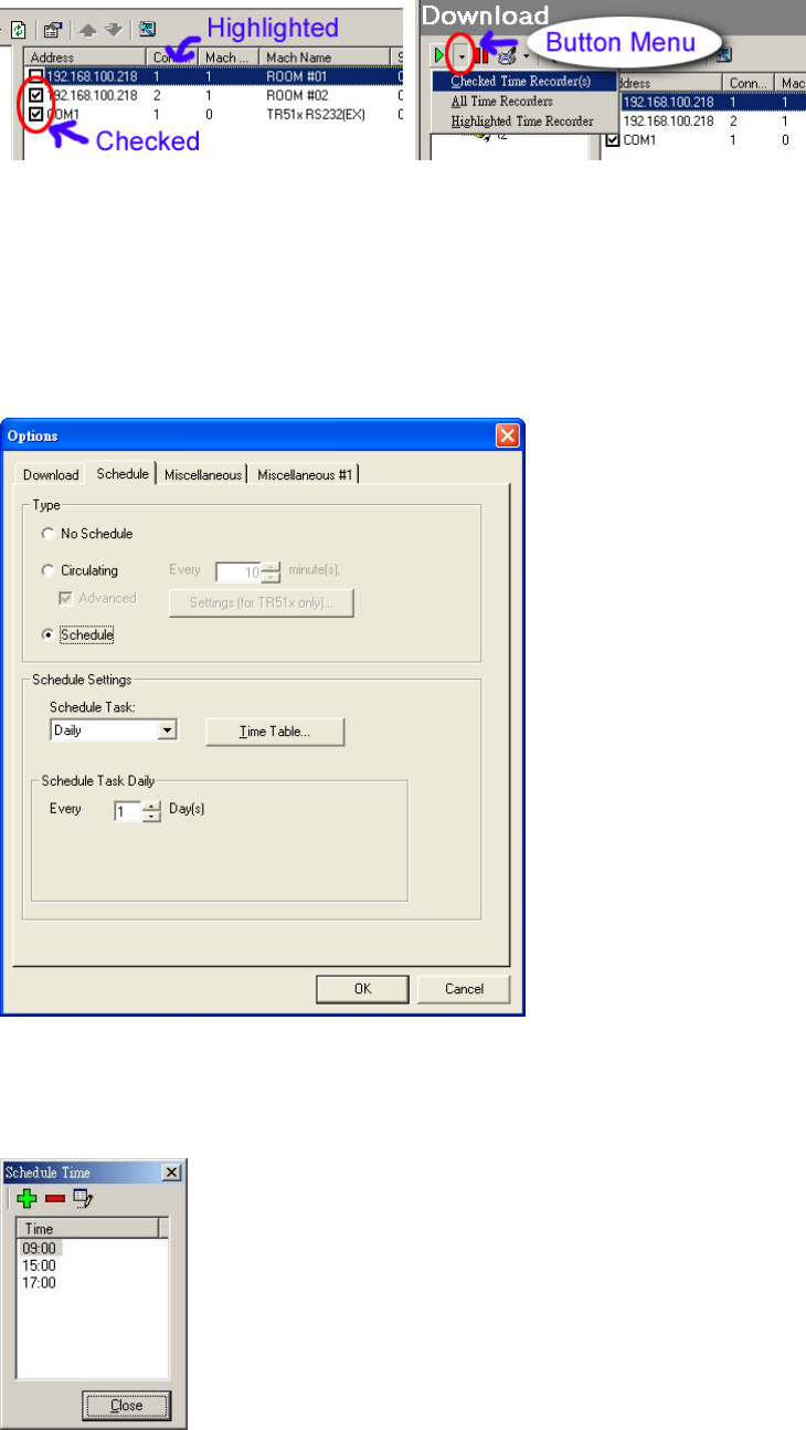
For flexible purposes, TRU also allows to download the highlighted one or specified terminals. To do
this, click the button menu of button, then click [Highlighted Time Recorder] or [Checked Time
Recorder(s)].
32
Scheduling:
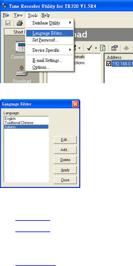
By using Scheduling, you can schedule any time to download the time data. Scheduling starts each time
you start the TRU program and is able to run in the background. With Scheduling, you can schedule a
time to download time data daily, weekly, monthly, or at certain times. To configure the scheduled time,
from [Tools] menu, click [Options]. On the [Options] window, click [Schedule] tab.
To enable the Scheduling function, select the Type to Schedule.
First, select the [Schedule Task] for days period of scheduling, and then click [Time Table] to edit the
specified times of downloading time data.
After completing the scheduling configuration, click [OK] to activate the settings.
33
5.3.4 Language Editor
The Language Editor provides a way to localize the interface of TRU. You can use this function to create a
new native language interface, which is translated from the default used English. The translation needs to be
done on your own. For example, for Italian, the “Name” translates to “Nome”.
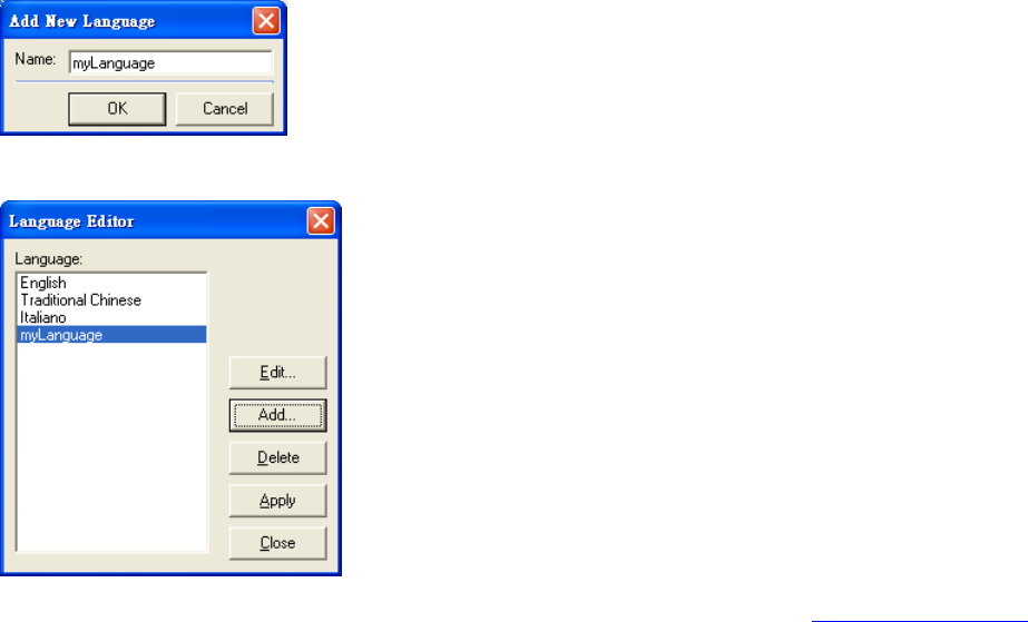
To launch the Language Editor dialog, on the Tools menu, click Language Editor.
Shown below is the screenshot of Language Editor dialog.
This dialog has the following area and controls:
Language list box: Displays current supported languages.
Edit button: Modifies the string table of selected language.
Add button: Adds a new language.
Delete button: Deletes the selected language. Please take note, the English and current applied language
can’t not be deleted.
Apply button: Applies the selected language to be the TRU interface used.
Close button: Closes Language Editor dialog.
34
5.3.4.1 Adding New Language
In the Add New Language dialog, enter new language name.
Click OK to save the setting, the new language name will appear in the list box.
The next step is to edit the string table for the new language, please refer to Editing String Table.
5.3.4.2 Editing String Table
All the string used in the interface of TRU is stored in the StringList table of Res.mdb file (MS Access 2000
format). This file is located in the installation path of TRU.
Every language has its own column in StringList table, when adding a new language, TRU will create a
column in this table, and the column name is same to the language name.
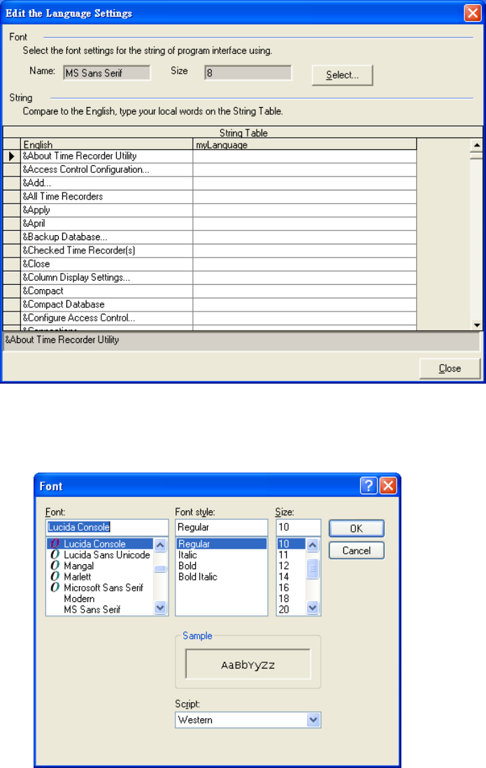
Shown below is the screenshot of Edit the Language Settings dialog.
35
This dialog has following areas and controls:
Font area: TRU will give a default font name and size for the new language. If your native language
has issue on this setting, please click Select to modify to meet your need.
Select button: Sets the font settings used in TRU interface.
String area: There is a String Table grid displaying two columns. The first column is always to be
English, which is read-only, displays all the string used in interface of the TRU program. The second
column is the selected language (or your native language). Comparing with string in English column,
translate and enter your native language in the cell of second column. When switching the focus of cell,
the enter value will be saved to Res.mdb database file immediately.
Close button: Close this dialog.

36
5.3.4.3 Applying Language
After clicking Apply button of Language Editor dialog, TRU will re-load the string in selected language
from the Res.mdb, and then displays the changes to the interface.
If there is string leave blank in the string table of applied language, TRU will use English string instead.
5.3.4.4 Notes
※Some string may include Enter key, you can enlarge the height of the cell to see the whole content of
string.
※If string includes Enter key, using [Ctrl]-[Enter] compound keys to entry the Enter key.
※The ‘&’ symbol is a hotkey operator. &File means the hotkey is F, &Save means the hotkey is S.
※If you want to put the new completed language in the setup file of TRU, then the file Res.mdb is needed
for packaging. Please contact your dealer’s salesman for details.
5.3.5 Maintain Database
From time to time, it is important for the TRU database to be backed up, purged and compacted. The
frequency at which these tasks are performed depend on the size of your time data and the speed at which
the TRU database file is growing.
Before we continue, read the definitions of each action that can be performed on the TRU database:
Backup Database – This function makes an copy of the TRU database as of the time the function is
executed. This is very useful for keeping a copy of your data file in case of a disaster. It should be
performed on a weekly basis or even more frequently if the data in TRU is extremely important. This
method of backup should not take the place of a normal daily tape backup.
Restore Database – This function can be used to import the backup database. Please keep in mind; the
current database settings will be overwritten by the imported database.
Compact Database – To increase performance, when records are deleted from the TRU database, they
are not permanently deleted. However, when many deleted records accumulate in the TRU database, it
can hinder performance. To permanently remove deleted records (and therefore reduce the size of the
database and increase performance) 'Compacting' the database is recommended on a monthly or
semi-monthly basis.
A good indication of when you should clear time data is when TRU performance seems to have slowed
considerably due to the increase in file size (usually well over 10MB). If reporting is taking much longer
than it used to, it might be time to clear time data.
All the database maintenances are all running under Normal Mode.

37
5.3.5.1 Backup Database
To backup data, follow these instructions:
From Tools menu, click Database Utility/Backup Database.
You will be asked to give a path name for the copy of the database. Enter a valid path name and click
OK.
5.3.5.2 Restore Database
To restore database, follow these instructions:
From Tools menu, click Database Utility/Restore Database.
You will be given a warning. Read the warning and click Yes if you wish to continue.
Specify the path that the backup database is located.
Click Open if you are certain you want to continue.
5.3.5.3 Compact Database
To compact the database, follow these instructions:
From Tools menu, click Database Utility/Compact Database.
5.3.6 Loading TR320 Manager Software
TR320 Manager Software is mainly used to establish the users and messages information. To load this
software, see following:
1. On the Tools, point to Device Specific.
2. Click TR320.
38
5.4 TR320 Manager
5.4.1 The first execution
5.4.1.1 Check login password
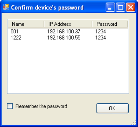
‧ Check the password is correct or not for each machine
‧ If all password is correct, click OK to skip this section
‧ Double click machine in list and enter the right password
‧ Tick Remember the password , this dialog cannot show in next time
39
5.4.2 Create a tree structure
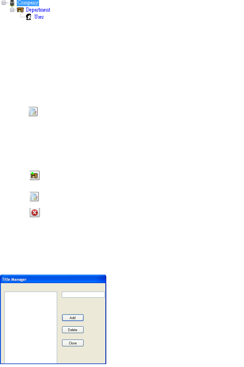
5.4.2.1 Company
‧ This is the top (level 1) node of tree
‧ Only a company node exist in TR320 Manager
TR320 ManagerTR320 Manager
TR320 Manager
‧ This node cannot remove
‧ Click to modify company name
5.4.2.2 Department
‧ This is level 2 node of tree
‧ Click to add a department
‧ Click
to modify department(current node) name
‧ Click to delete department(current node)
※
※※
※Users under the department will delete, after this step.
Users under the department will delete, after this step.Users under the department will delete, after this step.
Users under the department will delete, after this step.
5.4.2.3 Title
Tools →Title manager
Add
‧ Enter title name
‧ Click Add
Delete
‧ Select a title
‧ Click Delete
40
5.4.2.4 User (Employees)
‧ This is level 3 node of tree
‧ Click to add a user
‧ Click to modify user(current node) name
‧ Click to delete user(current node)
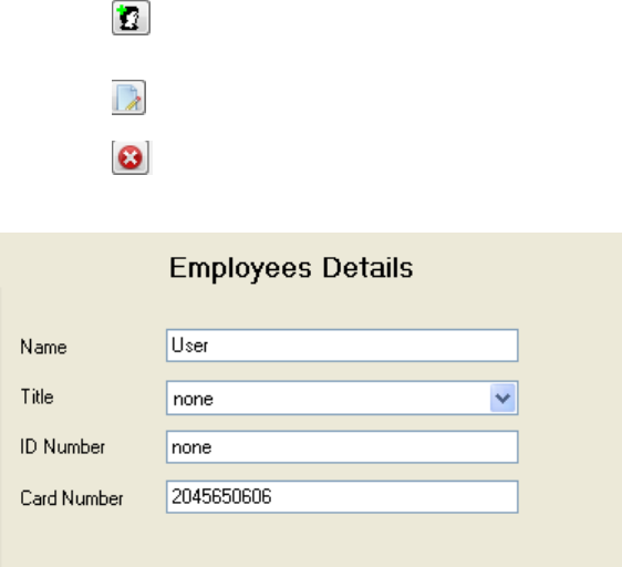
‧ An user with the following properties
Name: User’s name can modify in here
Title: Select a title
ID Number: Enter the ID in this column , it indicates to your human resource or other number
you want to use.
Card Number: Enter Tag’s ID number.
41
5.4.3 Information
5.4.3.1 Create message template (*.mt) file
Tools →Templet Editor
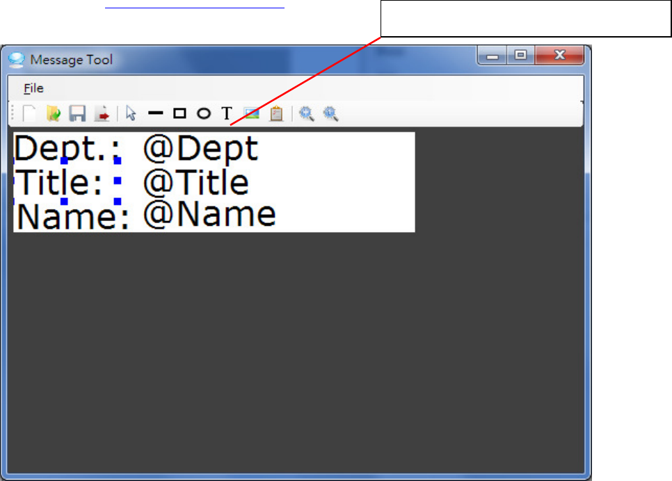
Please reference Appendix-A Message Tool
Insert textbox to create to template
5.4.3.2 Bind to database
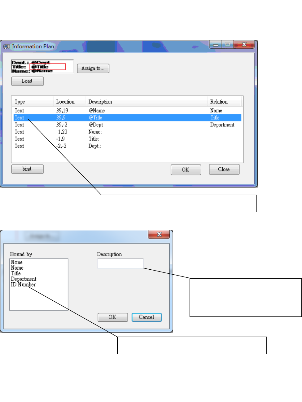
This tool use to assign the different image of information to each user. The image will change if you bind the
Textbox
42
different data.
The message template file (*.mt) contains several component on canvas. The text component edited in
Message Tool can bind data in TR320 Manager,
Image → Information → click “Load” button
Laod *.mt file you made by template editor.
Click “bind” after you selected.
Click “OK” to confirm your setting .
5.4.3.3 Assign to users (Employees)
Please reference 3-4 Search function
After the bind step, the relation column will display what you bound.
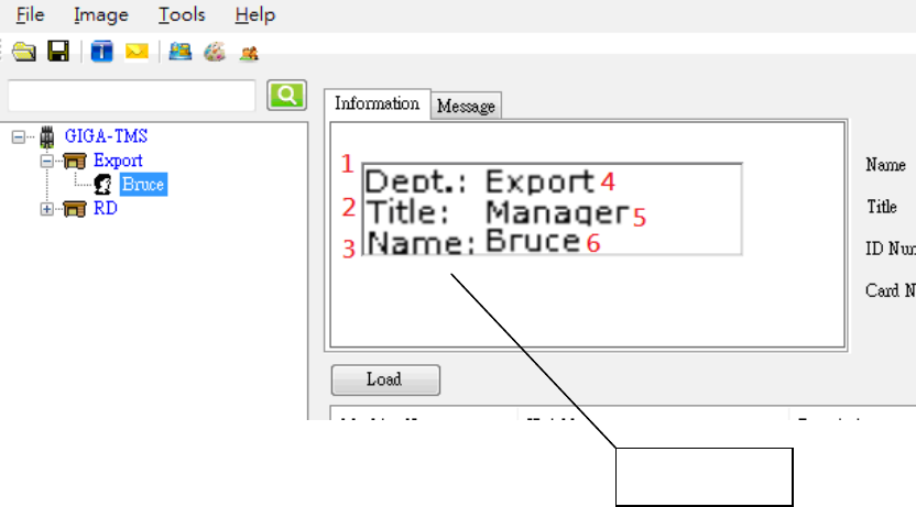
Select the textbox or other type item here
Select the data you want to bind
If you don’t want to bind any
data , Just select “None” , and
enter words here.
43
Check the relation column,and click “Assign to” to assign the picture to users.
Click “OK” to comfirm and Click “Close” to close Information function
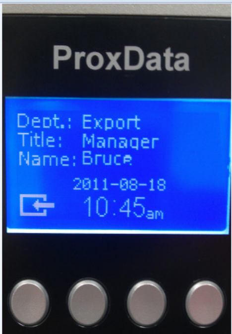
Check the following result
1 The text field with fix word Dept.:
2 The text field with fix word Title:
3 The text field with fix word Name:
4 The text field was bound by the data which is Department
5 The text field was bound by the data which is Title
6 The text field was bound by the data which is Name
The result
44
The result on TR320
45
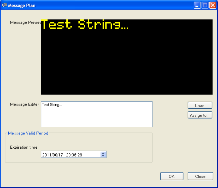
5.4.3.4 Message
Image → Message
5.4.3.4.1 Leave message
‧ Input message in Message Editor
3-4-2 Set expiration time
The message will delete at the time in TR320
46
The default value is current time add 7 days
3-4-2 Assign to User (Employees)
Same as 3-3-3
5.4.3.5 Update to machine
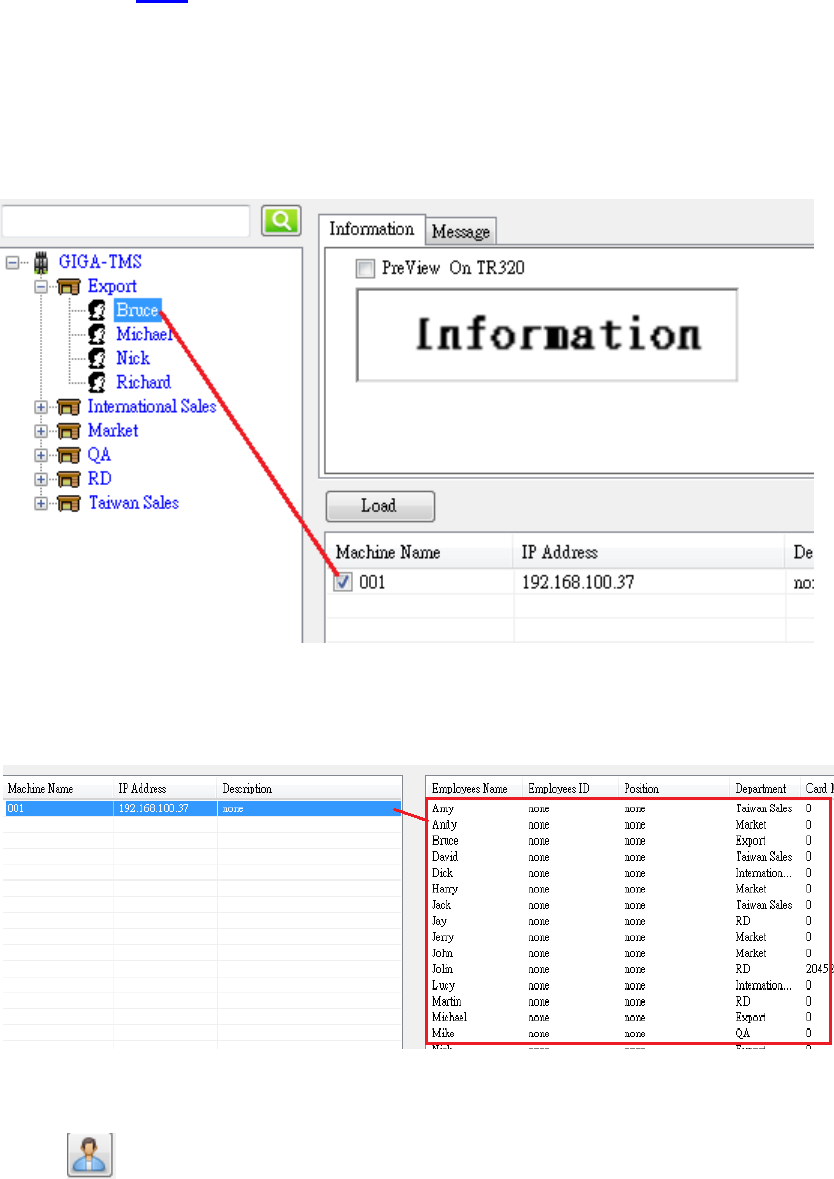
Before update to machine , we have to create the relataion between user and machine.Please check the
following picture
This picture express “Bruce” will update to “Machine 001”
Tools→Machine User Manager
This picture express the marked users will update to “Machine 001”
Click to modify users for currect machine
3-5-1 Information
Update white list to TR320, the old data in TR320 will disappear.
47
The newest user data in TR320 Manager will replace the old.
Update information image for each user
3-5-2 Message
Select users
Update message to selected users
3-5-2 Both
Update white list and message to TR320
All users and message will refresh
The old message expiration time will reset to the current time add 7 days
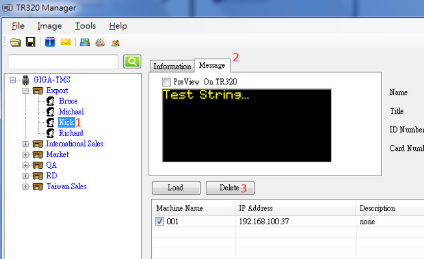
5.4.3.6 Delete message
In main windows (Only delete a message in a time)
Select a user
Switch to Message page
Click Delete
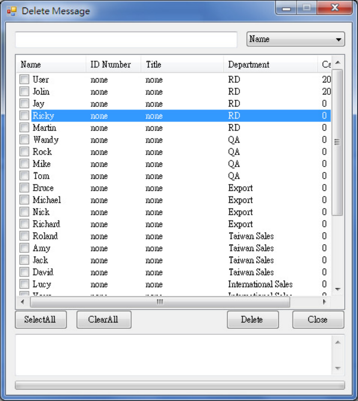
Image→Delete Message (Delete many message in a time)
48
Select users
Click Delete after selected and close this windows
49
5.4.3.7 Change machine image
Tools→Machine Image Manager
Select Logo, In, Out….etc,
Load other image or edit to replace the old one
* Loa
LoaLoa
Load
dd
d
We only support the bitmap that pixel level is 1 bit
We only support the bitmap that pixel level is 1 bitWe only support the bitmap that pixel level is 1 bit
We only support the bitmap that pixel level is 1 bit
If click edit, you just need save file after modify
Select the machine
Click Update To Machine
Click Reset To Default to reset to default image
5.4.3.8 Search function
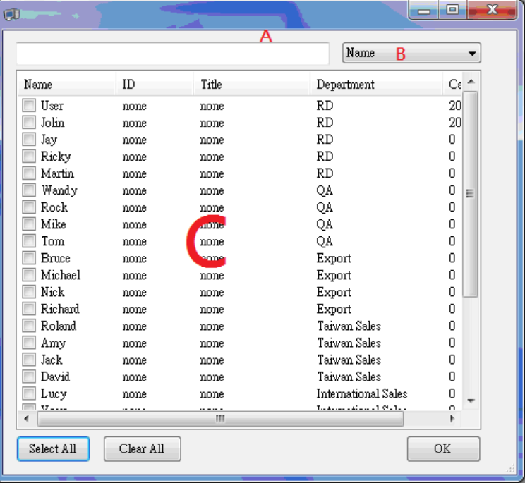
In Assign to, User Information, Delete Message, we can see the following picture.
A: Search condition
B: Search by Name, Department, Title, ID, Card Number
50
C: Result
In main windows
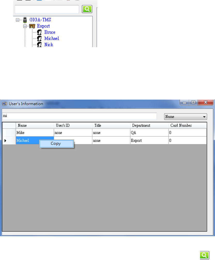
◆Search an user by this column and button
◆The name have to correct absolutely
Ask: If I don’t know the user’s full name, how can I search in main windows?
Ans: Tools →user’s Information
◆
◆◆
◆Search by fuzzy match here, right click on the name and click Copy
◆
◆◆
◆Close this windows, paste on the search columns in main window and click
Close this windows, paste on the search columns in main window and click Close this windows, paste on the search columns in main window and click
Close this windows, paste on the search columns in main window and click
5.4.3.9 Backup
Export Database: Output a *.bak file. This file include user’s data, the relation between user
and machine
Import Database: Input a *.bak file. The current database will clear and replaced by the input
file.
51
Load Empty database: Erase all data by this step
5.5 Appendix-A
5.5.1 .
..
.A-1 Message Tool
The Message Tool is used to create a message template and design the layout by using template
components.
5.5.1.1 Overview of Message Tool Window
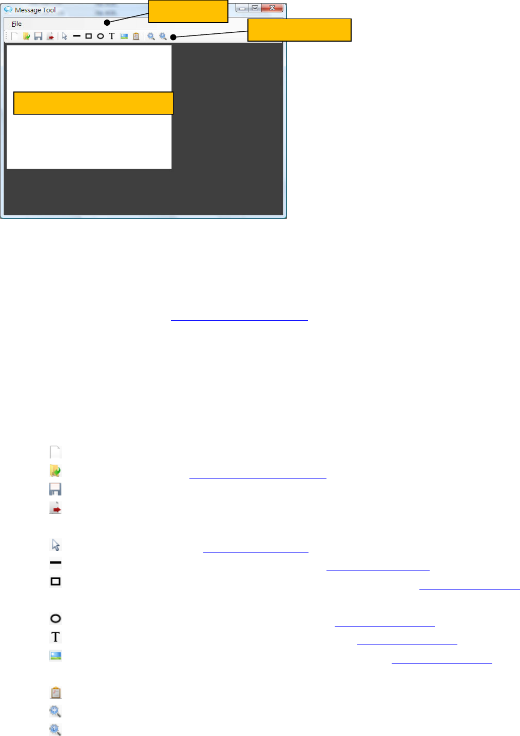
Shown below is the screen shot of Message Tool window.
52
The Message Tool window has following elements:
Menu bar
File menu
New: Create a new message template.
Open: Select an existed message template file(*.mt) and display it to a canvas.
Save: Save the changes of loaded file.
Save As: Save the message template to a specified file.
Export: Export the message template to a BMP or JPG file.
Close: Unload Message Tool window.
Tool bar
File tools
New: Create a new empty message template.
Open: Select an existed message template file(*.mt) and display it to a canvas.
Save: Save the changes of loaded file.
Export: Export the message template to a BMP or JPG file.
Template component tools
Pointer: Lets you to select template components.
Draw Line: Draw a straight line shape by using line template component in the canvas.
Draw Rectangle: Draw a rectangle or square shape by using rectangle template component in
the canvas.
Draw Ellipse: Draw an ellipse shape by using ellipse template component in the canvas.
Draw Text: Type and format a textual string by using text template component in the canvas.
Draw Image: Insert an image from an image file by using image template component in the
canvas.
Property: Modify the properties of selected template component.
Zoom In: Large size view of canvas.
Zoom out: Normal side view of canvas.
Menu bar
Toolbar
Canvas
53
Canvas
Displays the layout and contents of template components designed in message template.
5.5.1.2 Template Components
The template components are used to draw in canvas. There are three types of template components, which
are:
Shape and line component: Draw shapes and lines in the canvas.
Text component: Type text in the canvas.
Image component: Insert an image in the canvas.
The template component can be put in any place of canvas. You can select the component then to remove
and resize it.
5.5.1.3 Drawing Shapes and Lines
Following procedure shows you how to draw a shape or line in the canvas.
1. Select the shape or line component in the toolbar.
2. Drag in the document to draw the shape or line. Release the mouse when you are done.
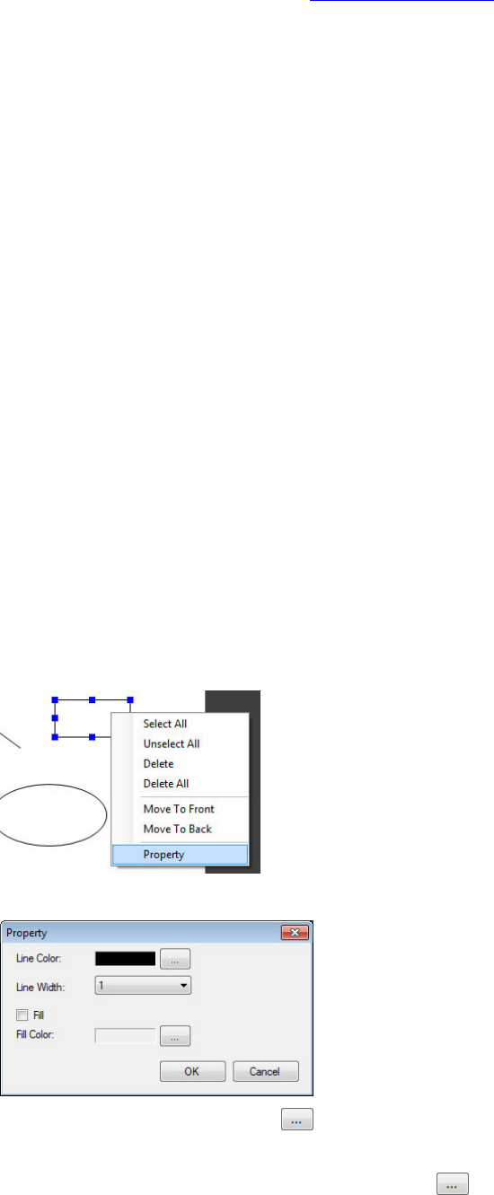
5.5.1.4 Modifying Shapes and Lines
Following procedure shows you how to modify a selected shape or line in the canvas.
1. Right-click to select the shape or line component in the document, click Property.
2. In the shape/line Property dialog, you can:
* Change the line color: Click to select the line color.
* Change the line width: In the Line Width box, select a line width.
* Fill color: Select Fill check box, and then click to select the color to fill.
54
5.5.1.5 Deleting Shapes and Lines
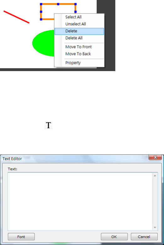
Following procedure shows you how to delete a selected shape or line in the canvas.
1. Right-click to select the shape or line component in the document, click Delete.
5.5.1.6 Typing Text
Following procedure shows you how to type text at a point in the canvas.
1. Click the text component in the toolbar.
2. In the Text Editor dialog, type characters or words in the Text box. Click Font to modify the text
property.
3. Click OK and click in the document to set an insertion point for the text.
4. Drag in the document to decide the cutoff. Release the mouse when you are done.
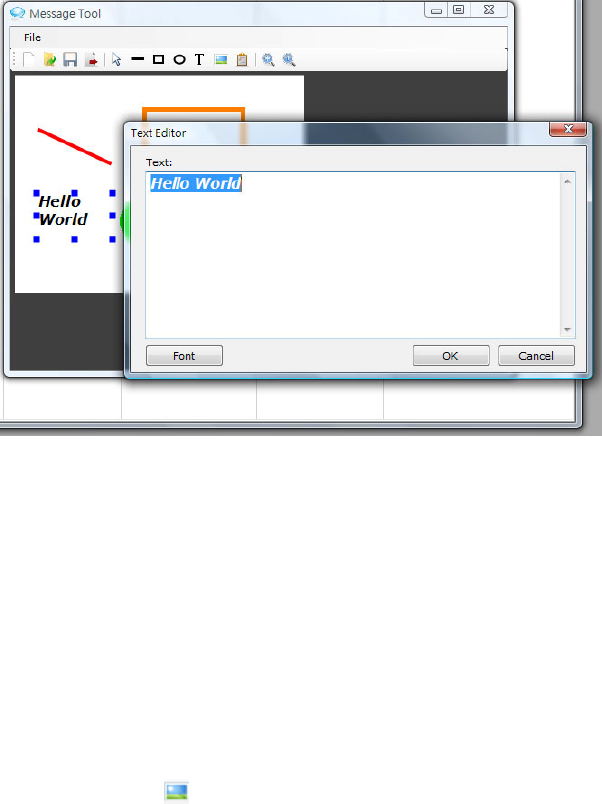
5.5.1.7 Modifying Text
Following procedure shows you how to modify a selected text in the canvas.
1. Right-click to select the text in the document, click Property.
2. In the Text Editor dialog, modify the text properties and then click OK.
55
5.5.1.8 Deleting Text
Following procedure shows you how to delete text in the canvas.
2. Right-click to select the text component in the document, click Delete.
5.5.1.9 Inserting Image
Following procedure shows you how to insert an image in the canvas.
1. Click the image component in the toolbar and then select the image file.
2. Click OK and then click in the document to set an insertion point for the image.
3. Drag in the document to decide the cutoff. Release the mouse when you are done.
5.5.1.10 Changing Image
Following procedure shows you how to change a selected image in the canvas.
1. Right-click to select the image in the document, click Property.
2. Select an image file and then click OK.
5.5.1.11 Deleting Image
Following procedure shows you how to delete image in the canvas.
3. Right-click to select the image component in the document, click Delete.
5.5.1.12 Saving Message Template
The message template is a text file format and the file extension is “mt”. When you finish the design of

56
message template, in the toolbar, click save button to save the changes.
If you want to save to other path, do the following:
1. On the File menu, click Save As.
2. Indicate the path to be saved to and then click OK.
5.5.1.13 Exporting Message Template
Message Tool supports to transfer the message template to a graphic image file. You can export to BMP or
JPG format image. To export the message template, do the following:
1. On the File menu, click Export.
2. Indicate the path to be exported to.
3. Enter the file name.
4. Select the format of graphic image.
5. Click OK.