GIL Technology GILBS WiMax Outdoor CPE (N-TYPE) User Manual rev 0415
GIL Technology. CO., Ltd WiMax Outdoor CPE (N-TYPE) rev 0415
User manual rev 0415
GIL Technology
LIBRA 5816
Quick Start
Dec 2008

2 LIBRA 5816 Series User Manual
Contents
Contents ..................................................................................................... 2
Important Information ............................................................................. 5
Safety considerations .............................................................................................................. 5
Warning symbols used in this book 5
Notices ........................................................................................................ 6
Copyright notice ...................................................................................................................... 6
Regulatory notice .................................................................................................................... 6
Other notices ........................................................................................................................... 6
Warranty & repair .................................................................................................................... 7
Customer support contacts ...................................................................................................... 7
Distributor technical support 7
Contacting GIL Technical Support 7
GIL product information 7
Publication history .................................................................................................................. 7
3 LIBRA 5816 Series User Manual
Description ................................................................................................ 8
Overview ..................................................................................................................................8
Hardware & Check list .............................................................................................................9
Package Contents 10
LIBRA 5816 BS contents 10
LIBRA 5816 SS contents 11
LIBRA 5816 LSS contents 12
Configuration Diagram—LIBRA 5816 BS 13
Configuration Diagram—LIBRA 5816 SS & LSS 14
Physical Description ........................................................................................................... 16
LIBRA 5816 BS (Base Station) 16
LIBRA 5816 SS (Subscriber Station) 17
LIBRA 5816 LSS(Long Range Subscriber Station) 18
LIBRA 5816 Series System Features .................................................................................... 19
Base Station (BS) Equipment 20
Subscriber Station (SS) Equipment 21
Long Range Subscriber Station (LSS) Equipment 22
About Point-to-Point (P-P) Systems ..................................................................................... 23
Base Station (BS) Equipment 23
Subscriber Station (SS) Equipment 23
Long Range Subscriber Station (LSS) Equipment 24
Specifications ......................................................................................................................... 25
Getting Started ................................................................................... 26
Introduction ............................................................................................................................ 26
Field Installation of the LIBRA 5816 Device ........................................................................ 26
Field Preparations 27
Tools and Equipments 27
LIBRA 5816 Installation Procedure ...................................................................................... 28
Mounting Instruction ......................................................................................................................................... 28
LIBRA 5816 Quick Start Guide ..................................................... 3 3
Initial Configuration ............................................................................................................... 33
Connection Confirmation 34
4 LIBRA 5816 Series User Manual
LIBRA 5816 Web Login Access 36
Basic WiMAX Configuration/Link Status Check 37
BS/SS Key Configuration 41
Troubleshooting .................................................................................. 53
General Principles ................................................................................................................... 53
Considerations on Regular Maintenance and Failure Treatment ............................................ 53
N
etwork Integrity 53
RF Link Quality 53
Transmission Module 53
Proper Unit Configuration 53
Troubleshooting Table ............................................................................................................ 54
Appendix A: Specifications for Lightning Protection of GIL ........ 57

5 LIBRA 5816 Series User Manual
Important Information
Safety considerations
This document must be reviewed for familiarization with the product, instructions, and safety symbols
before operation.
Verify that local safety regulations are adhered to during installation with regard to grounding and
lightning protection.
Verify that the correct AC power source is available for the Power Inserter.
Disconnect the product from operating power before cleaning.
Warning symbols used in this book
WARNING: Injury or death may result from failure to heed a WARNING.
Do not proceed beyond a WARNING until the indicated conditions are fully understood and met.
! CAUTION: Damage to equipment may result from failure to heed a caution.
Do not proceed beyond a ! CAUTION until the indicated conditions are understood and met.
Important: Indicates critical information to be aware of which may affect the completion of a task or
successful operation of equipment.
WARNING
All antennas must be installed by a knowledgeable and professional installer.
! CAUTION
An antenna must be connected to the BS, SS or LSS units before powering up the equipment.
Powering up equipment without an antenna connected can permanently damage the unit or
the RF transmission cable
6 LIBRA 5816 Series User Manual
Professional installation instruction
1. Installation personal
This product is designed for specific application and needs to be installed by a qualified personal
who has RF and related rule knowledge. The general user shall not attempt to install or change
the setting.
2. Installation location
The product shall be installed at a location where the radiating antenna can be kept 50 cm from
nearby person in normal operation condition to meet regulatory RF exposure requirement.
3. Effective power output
According to US Rule, CFR 47 part 15 Section 15.247 “Operation within the bands 902 - 928 MHz,
2400 - 2483.5 MHz, and 5725 - 5850 MHz”, the authorized maximum peak conducted output
power at antenna terminal is 0.319154 watt, 0.511682 watt, respectively for BS and SS, per the
measurement procedure as described in the rule part. Please refer to the related rules for detail.
4. Installation procedure
Please refer to user’s manual for the detail.
5. Warning
Please carefully select the installation position and make sure that the final output power does not
exceed the limit set force in US Rule CFR 47 part 15 section 15.247. The violation of the rule
could lead to serious federal penalty.

7 LIBRA 5816 Series User Manual
Notices
Copyright notice
Copyright© Dec 2008 GIL Technology
All rights reserved.
This guide and the application and hardware described herein are furnished under license and are
subject to a confidentiality agreement. The software and hardware can be used only in accordance
with the terms and conditions of this agreement.
No part of this guide may be reproduced or transmitted in any form or by any means – electronic,
mechanical, or otherwise, including photocopying and recording – without the express written
permission of GIL Technology
While every effort has been made to ensure that the information contained in this guide is correct,
GIL Technology does not warrant the information is free of errors or omissions.
Information contained in this guide is subject to change without notice.
Regulatory notice
Federal Communication Commission Interference Statement
This equipment has been tested and found to comply with the limits for a Class B digital
device, pursuant to Part 15 of the FCC Rules. These limits are designed to provide
reasonable protection against harmful interference in a residential installation. This
equipment generates, uses and can radiate radio frequency energy and, if not installed and
used in accordance with the instructions, may cause harmful interference to radio
communications. However, there is no guarantee that interference will not occur in a
particular installation. If this equipment does cause harmful interference to radio or
television reception, which can be determined by turning the equipment off and on, the user is
encouraged to try to correct the interference by one of the following measures:
- Reorient or relocate the receiving antenna.
- Increase the separation between the equipment and receiver.
- Connect the equipment into an outlet on a circuit different from that to which the receiver
is connected.
- Consult the dealer or an experienced radio/TV technician for help.
FCC Caution: Any changes or modifications not expressly approved by the party responsible
for compliance could void the user's authority to operate this equipment.
This device complies with Part 15 of the FCC Rules. Operation is subject to the following two
conditions: (1) This device may not cause harmful interference, and (2) this device must
accept any interference received, including interference that may cause undesired operation.
IMPORTANT NOTE:
Radiation Exposure Statement:
This equipment complies with FCC radiation exposure limits set forth for an uncontrolled environment. This
equipment should be installed and operated with minimum distance 50 cm between the radiator & your body.
8 LIBRA 5816 Series User Manual
This transmitter must not be co-located or operating in conjunction with any other antenna or
transmitter.
The availability of some specific channels and/or operational frequency bands are country
dependent and are firmware programmed at the factory to match the intended destination.
The firmware setting is not accessible by the end user.
Industry Canada statement
This device complies with RSS-210 of the Industry Canada Rules. Operation is subject to the
following two conditions: (1) This device may not cause harmful interference, and (2) this
device must accept any interference received, including interference that may cause
undesired operation.
IMPORTANT NOTE:
Radiation Exposure Statement:
This equipment complies with IC radiation exposure limits set forth for an uncontrolled environment. This
equipment should be installed and operated with minimum distance 50 cm between the radiator & your body.
This device has been designed to operate with an antenna having a maximum gain of 16.5
dBi. Antenna having a higher gain is strictly prohibited per regulations of Industry Canada.
The required antenna impedance is 50 ohms.
! Caution: This product is designed specific for point to point operation, the point to multi
point operation is prohibited.
Other notices
Changes or modifications to the equipment not expressly approved by GIL Technology could void the
user’s authority to operate the equipment.
Appropriately shielded remote I/O serial cable with the metal connector shell and cable shield
properly connected to chassis ground shall be used to reduce the radio frequency interference.
All antenna installation work shall be carried out by a knowledgeable and professional installer. The
parts in some LIBRA 5816 versions are Imperial sizes – inches and fractions of an inch. Do not attempt
to mix Imperial nuts, bolts and screws with similar metric hardware. This will strip the threads.

Description
9 LIBRA 5816 Series User Manual
Warranty & Repair
Please contact the party from whom you purchased the product for warranty and repair information. GIL
provides no direct warranty to end users of this product.
Customer support contacts
Users of GIL equipment who require technical assistance must contact their reseller or distributor.
Distributor technical support
Distributors may contact GIL’s Technical Support on GIL’s products.
When requesting support, please have the following information available
" configuration of the system, including models of GIL equipment, versions and serial
numbers
" antenna type and cable lengths
" site information, including possible RF path problems, such as trees, buildings and other RF
equipment in the area
" distance of the RF link
" configuration of unit.
" description of the problem
Contacting GIL Technical Support
By Telephone Call: +886-2-8751-2366 Business hours: 9:00 a.m. to 6:00 p.m. (GMT +8)
By Email Please send an email to:gilsupport@gil.com.tw
GIL product information
To obtain information regarding GIL products, contact the GIL distributor in your region, or call
+886-2-8751-2366 to speak with a GIL sales representative or visit our web site at http://www.gil.com.tw.
Publication history
RevisionDateDescription
Rev 1Dec 2008First public release of this manual.

Description
10 LIBRA 5816 Series User Manual
Description
Overview
This information in this guide applies to the "LIBRA 5816" Series products, including the following.
Data Rate Channel Size BWS Model Frequency
(TDD System)
72Mbps
/56Mbps(20MHz) 20 MHz / 15 MHz ;
10 MHz / 5 MHz LIBRA 5816 BS TX&RX:5725-5850
72Mbps
/56Mbps(20MHz) 20 MHz / 15 MHz ;
10 MHz / 5 MHz LIBRA 5816 SS TX&RX:5725-5850
72Mbps
/56Mbps(20MHz) 20 MHz / 15 MHz ;
10 MHz / 5 MHz LIBRA 5816 LSS TX&RX:5725-5850
This chapter presents an overview of the LIBRA 5816 Series product.
Description
11 LIBRA 5816 Series User Manual
Hardware & Check list
There are 3 types of LIBRA 5816 radios:
z LIBRA 5816 Base Station (BS)
z LIBRA 5816 Subscriber Station (SS)
z LIBRA 5816 Long Range Subscriber Station (LSS)

Description
12 LIBRA 5816 Series User Manual
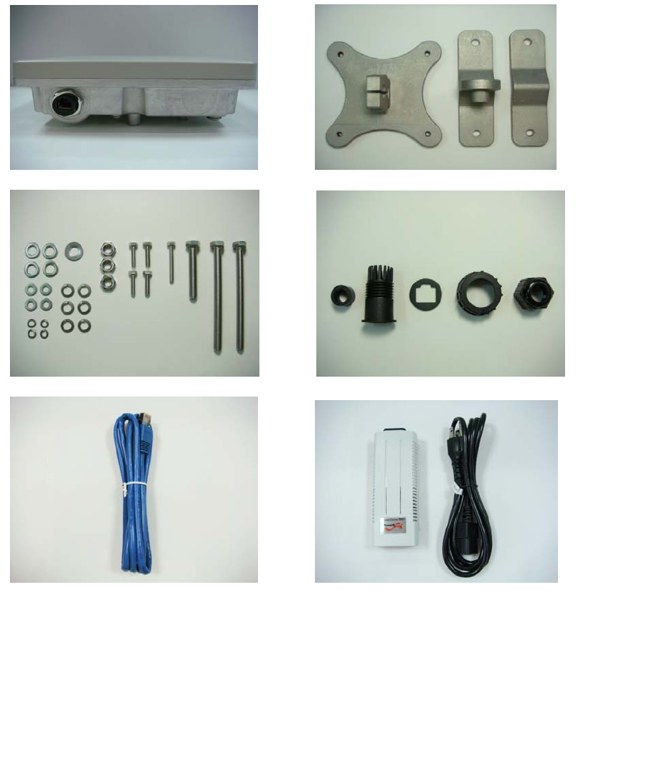
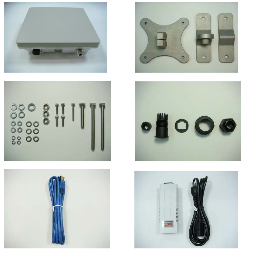
Package Contents
LIBRA 5816 package contains:
1. LIBRA 5816 radio
2. Mounting main frame
3. Mounting nuts and bolts
4. Waterproof cap for PoE Cable
5. Ethernet cable (indoor type)
6. PoE Power adaptor and electrical wire
There might be items of optional order in the package. Please contact your distributor if any of the
above basic items is missing.
z LIBRA 5816 BS contents
1.LIBRA5816BS2. Mounting main frame
3.Mounting nuts and bolts 4. Waterproof cap for PoE Cable
5. Ethernet cable (indoor type) 6. PoE Power adaptor and electrical wire-BS
Description
13 LIBRA 5816 Series User Manual
z LIBRA 5816 SS
Description
14 LIBRA 5816 Series User Manual
z LIBRA 5816 LSS
Description
15 LIBRA 5816 Series User Manual
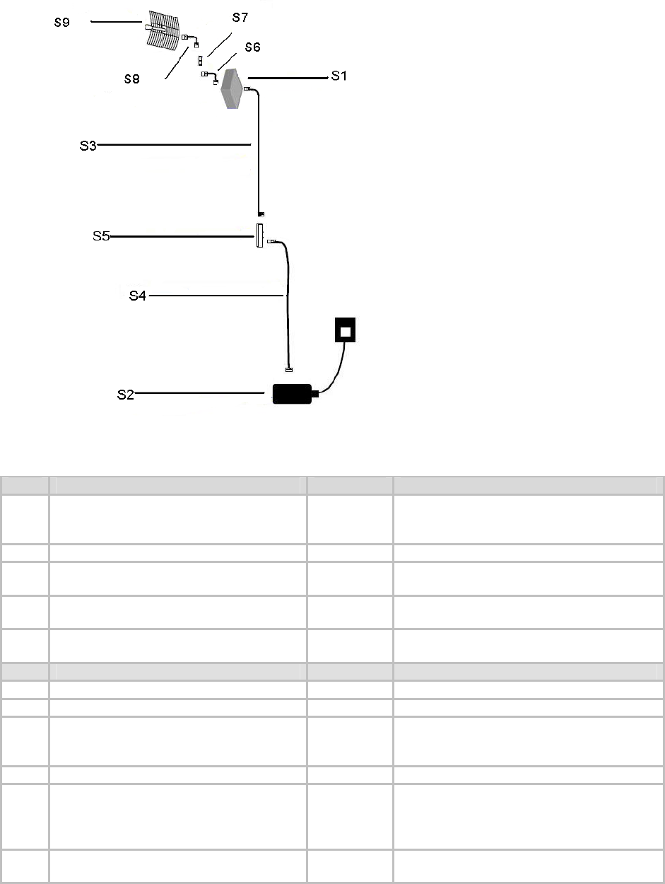
Configuration Diagram—LIBRA 5816 BS
Item Description Part No. Notes
S1 LIBRA 5816 – BS External 9900-0006 Unit also includes mounting kit &
weatherproof cap, which are not shown
here.
S2 Power Inserter 4000-0025
S3 10m Outdoor Shielded CAT5
Power-over-Ethernet cable 6010-1414
30m Outdoor Shielded CAT5
Power-over-Ethernet cable 6010-1415
100m Outdoor Shielded CAT5
Power-over-Ethernet cable 6010-1416
Item Description Part No. Notes
S4 1.5m Indoor CAT5 Cable 6030-0018 Included in Standard Package
S5 Ethernet Surge Suppressor 1220-0042 Optional (Recommended)
S6 100cm (36inch), LMR400 Ultra-Flex,
Patch, N(M)-N(M) 6010-0019 The given part number is an N type (Male)
to N type (Male), assuming the Surge
Suppressor has an N type (Female).
S7 Surge Suppressor @ 5.8GHz 1220-0025 Optional (Recommended)
S8 30cm (12inch), LMR400 Ultra-Flex,
Patch, N(M)-N(M) 6010-0014 The given part number is an N type (Male)
to N type (Male), assuming the surge
suppressor and selected antenna has an
N type (Female).
S9 5.8GHz 29dBi 8° Grid 1220-0601 Gil Technology certified Grid-Antenna
with mounting Kit
Description
16 LIBRA 5816 Series User Manual
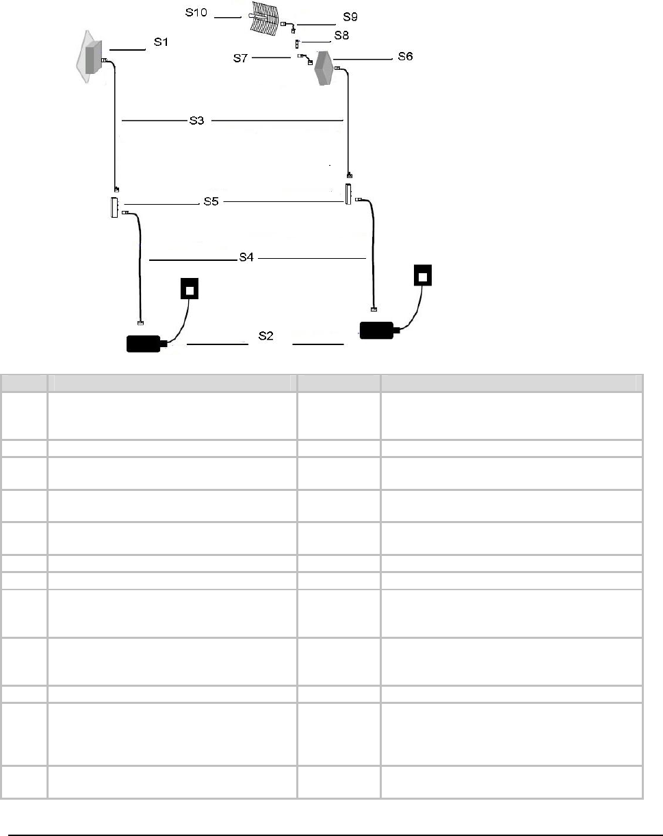
Configuration Diagram—LIBRA 5816 SS & LSS
Item Description Part No. Notes
S1 LIBRA 5816 – SS (Integrated with 18dBi
antenna) 9900-0007 It includes an integrated antenna. Unit
also includes mounting kit & weatherproof
cap, which are not shown here.
S2 Power Inserter 4000-0025
S3 10m Outdoor Shielded CAT5
Power-over-Ethernet cable 6010-1414
30m Outdoor Shielded CAT5
Power-over-Ethernet cable 6010-1415
100m Outdoor Shielded CAT5
Power-over-Ethernet cable 6010-1416
S4 1.5m Indoor CAT5 Cable 6030-0018 Included in Standard Package
S5 Ethernet Surge Suppressor 1220-0042 Optional (Recommended)
S6 LIBRA 5816 - LSS (External antenna
needed) 9900-0008 Unit also includes mounting kit &
weatherproof cap, which are not shown
here.
S7 100cm (36inch), LMR400 Ultra-Flex,
Patch, N(M)-N(M) 6010-0019 The given part number is an N type (Male)
to N type (Male), assuming the Surge
Suppressor has an N type (Female).
S8 Surge Suppressor @ 5.8GHz 1220-0025 Optional (Recommended)
S9 30cm (12inch), LMR400 Ultra-Flex,
Patch, N(M)-N(M) 6010-0014 The given part number is an N type (Male)
to N type (Male), assuming the surge
suppressor and selected antenna has an
N type (Female).
S10 5.8GHz 29dBi 8° Grid 1220-0601 Gil Technology certified Grid-Antenna
with mounting Kit
Description
17 LIBRA 5816 Series User Manual
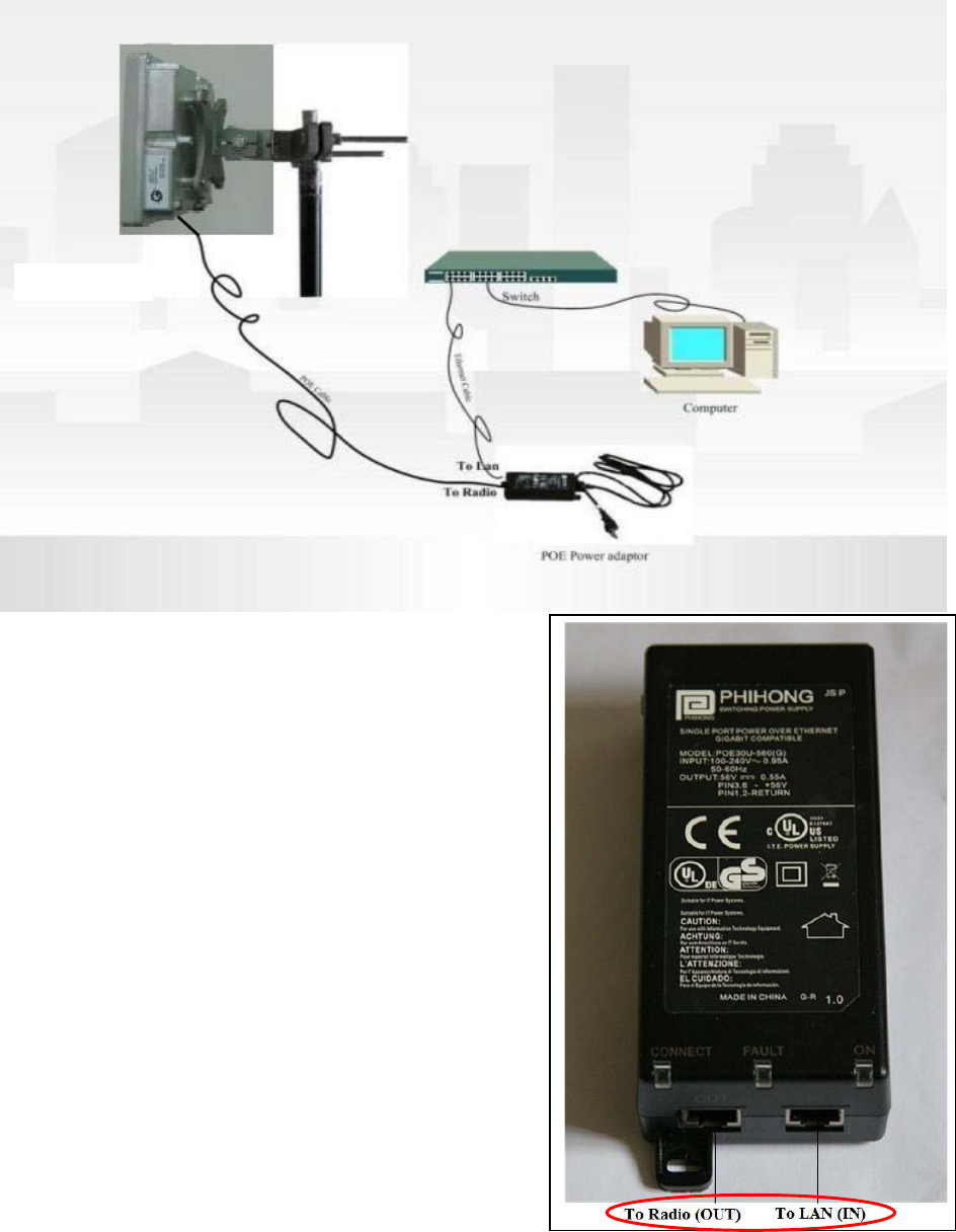
1. Basic Connection
Important:
LIBRA 5816 is powered by PoE (Power over Ethernet).
There are LAN and WAN port available for connection,
as shown in the picture.
LIBRA5816
Description
18 LIBRA 5816 Series User Manual
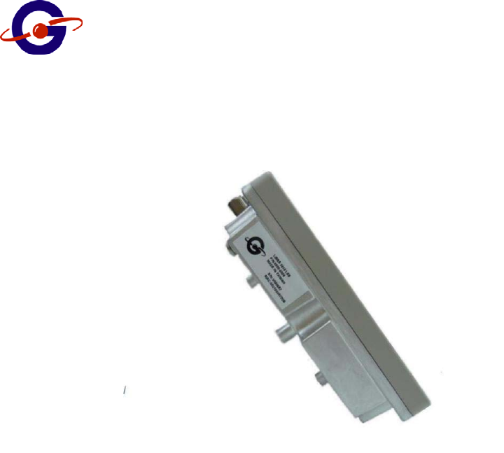
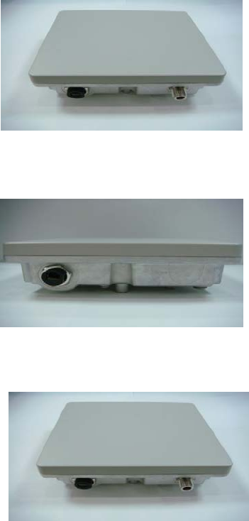
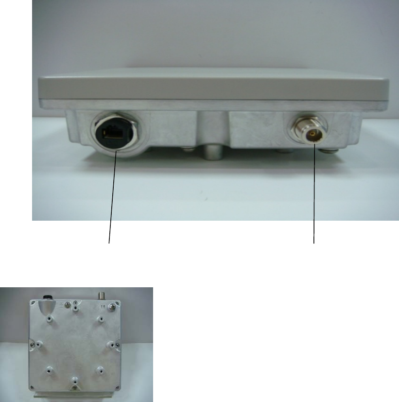
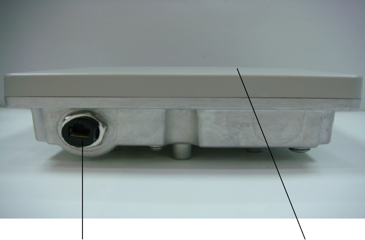
Physical Description
This section describes the components of the LIBRA 5816 BS and SS/LSS
" LIBRA 5816 BS(Base Station)
The LIBRA 5816 BS is an outdoor radio with IP67 enclosure providing PoE and data
transmission through RJ45 connector. N type RF connector can be mounted with any outdoor
5.8GHz antenna. The back panel owns 8 holes to mount flexibly on the pole or tower(As shown
in the picture below)
The back panel of LIBRA 5816
The physical dimensions of the LIBRA 5816 is 203mm(Height), 203mm(width)and 65mm(depth) or
8”,8”,2.5”) with the weight is 1.3kg(or 2.8Ib)
RJ45
NtypeRF
connector
Description
19 LIBRA 5816 Series User Manual
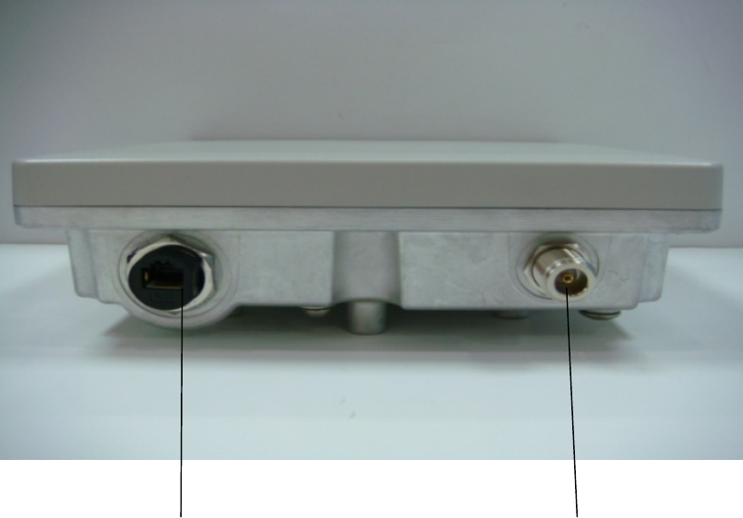
LIBRA 5816 SS(Subscriber Station)
The LIBRA 5816 SS is an outdoor radio with IP67 enclosure providing PoE and data transmission
through RJ45 connector. With the integrated 18dBi antenna that provides the convenience for rapid
deployment. The back panel owns 8 holes to mount flexibly on the pole or tower.
RJ45Integrated18dBiantenna
The physical dimensions of the LIBRA 5816 is 203mm(Height), 203mm(width)and 65mm(depth) or
8”,8”,2.5”) with the weight is 1.35kg(or 2.9Ib)
Description
20 LIBRA 5816 Series User Manual
LIBRA 5816 LSS(Long Range Subscriber Station)
The LIBRA 5816 LSS is an outdoor radio with IP67 enclosure providing PoE and data transmission
through RJ45 connector. N type RF connector can be mounted with any outdoor
5.8GHz antenna. The back panel owns 8 holes to mount flexibly on the pole or tower.
RJ 45 NtypeRFconnector
The physical dimensions of the LIBRA 5816 is 203mm(Height), 203mm(width)and 65mm(depth) or
8”,8”,2.5”) with the weight is 1.3kg(or 2.8Ib)
Description
21 LIBRA 5816 Series User Manual
LIBRA 5816 Series System Features
" Operating in 5.8GHz ISM band - No licensing fee required in most countries
WiMAX-compatible products
" Provides Non Line of Sight (NLOS) coverage, high spectral efficiency, adaptive
modulations allowing robust RF network design and deployment
" Scalable design delivers a true broadband solution of up to 200 Mbps and
serves up to 2,400 users per cell
" Rich built-in networking features provide cost-effective solution
" Efficient bandwidth allocation makes wireless networks highly scalable
" Fully antenna integrated design with optional external antenna connector in a
IP67 weatherproof enclosure
" Provide greater spectral efficiency of 3.6Mbps/MHz than WiFi products 2.7Mbps/MHz
Description
22 LIBRA 5816 Series User Manual
LIBRA 5816 System Components
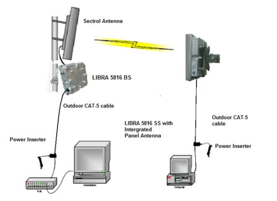
Base Station (BS) Equipment
The BS controls communication within the wireless network and is the main access point to the
Ethernet. The access point communicates with the SS’s in the system to provide each SS with
Access to the main network (ie Ethernet). The access point is typically located at a distance away
from the SS that will provide adequate radio signal strength for the specified data rates.
The Base Station is responsible for any Subscriber Station (SS) data management functions. The
LIBRA 5816 BS consists of three parts:
" BS radio unit,
" Ethernet Power Inserter with CAT-5 cable (bought separately) and weatherproofing kit(included),
and
" the External Antenna and cable (both bought separately)
" LIBRA 5816 BS– The BS is the main piece of radio equipment. It is designed for outdoor
installation but can also be installed indoors if needed. The BS is equipped with an N-type (F) RF
connector so that the external antenna can be connected to it. Thus many different types of base
stations can be deployed using sectoral, omni or other specialized antennas.
" Ethernet Power Inserter– This piece of equipment is a small box that connects between the SS
and the P.C. This box also provides power for the BS equipment to run. A CAT-5 outdoor cable is
Description
23 LIBRA 5816 Series User Manual
used to connect the Power inserter to the BS. The weatherproofing kit is used with standard
RJ-45 connector to ensure reliable connection for outdoor systems.
" Antenna and Cable– In order to accommodate different frequency re-use plans and scalability of
the base stations the BS is designed to be used with an external antenna. Antennas and cables
are selected by the user based on the network requirements.
Subscriber Station (SS) Equipment
The Subscriber Station connects customers to the Base Station via a wireless link. The link enables
customers to communicate with other users of the wireless network and the Ethernet. Subscriber
Station has two parts:
1) SS radio unit and
2) Ethernet Power Inserter with CAT-5 cable (bought separately) and weatherproofing kit (included).
" LIBRA 5816 SS– The SS is the main piece of equipment that would normally be installed
outdoors (indoor installation is permitted when feasible) The SS contains all of the necessary
radio equipment to provide a high-speed wireless link. The SS also has an integral antenna
such that no RF cables are required for a typical installation.
" Ethernet Power Inserter– This piece of equipment is a small box that connects between the
SS and the P.C. This box also provides power for the SS equipment to run. A CAT-5 outdoor
cable is used to connect the Power Inserter to the SS. The weatherproofing kit is used with
standard RJ-45 connector to ensure reliable connection for outdoor systems. Wireless network
activity focuses on the BS, which is both the main access point to the Ethernet (LAN or WAN)
and the destination for SS-originated communications (SSs do not communicate directly with
other SSs—they communicate only via the BS). SSs complete the customer-end of a wireless
link.
Long Range Subscriber Station (LSS) Equipment
The Long Range Subscriber Station (LSS) also connects customers to the BS via a wireless link. The
LSS enables the customer to reach longer ranges by allowing the connection to a higher gain
external antenna. It can also be used for indoor installation of the units should severe weather
conditions require it. The antenna is then mounted outdoors and connected via appropriate RF
cables to the unit. One other alternative which customers may want to consider is to use lower gain
Description
24 LIBRA 5816 Series User Manual
antennas with systems that are very close to the Base Station to mitigate some interference concerns
without recourse to dynamic power control.
The LIBRA 5816 LSS consists of three parts:
1) LSS,
2) Ethernet Power Inserter with CAT-5 cable (bought separately) and weatherproofing kit (included),
and
3) the External Antenna and cable (both bought separately).
" LIBRA 5816 LSS– The LSS is the main piece of equipment. It is designed for outdoor
installation but can also be installed indoors if needed. The LSS is equipped with an N-type
connector so that the external antenna can be connected to it. Thus the range of the system
can be significantly increased by use of higher gain antennas. Also, in situations where very
severe conditions may be encountered outdoors the LSS can be installed indoors with cabling
to the antenna outside.
" Ethernet Power Inserter– This piece of equipment is a small box that connects between the
LSS and the P.C. This box also provides power for the LSS equipment to run. A CAT-5 outdoor
cable is used to connect the Power inserter to the LSS. The weatherproofing kit is used with
standard RJ-45 connector to ensure reliable connection for outdoor systems.
" Antenna and Cable– In order to accommodate different range requirements for links, the LSS
is designed to be used with an external antenna. Antennas and cables are selected by the
user based on the network requirements.
About Point-to-Point (P-P) Systems
z Base Station (BS) To Subscriber Station (SS)
z Base Station (BS) To Long Range Subscriber Station (LSS)
For P-P systems LIBRA 5816 comes in three versions, Base Station (BS) 、Subscriber Station (SS)
Description
25 LIBRA 5816 Series User Manual
and the Long Range Subscriber Station (LSS).P-P links are used when only two locations are
connected, for example for backhaul purposes between Base Stations and the Network Operating
Center for connection to the Internet backbone, or in situations where throughput requirements
between two locations are such that the bandwidth can’t be shared.It can provide two kinds to choose.
(BS to SS or BS to LSS)
Base Station (BS) Equipment
The BS controls communication within the wireless network and is the main access point to the
Ethernet. The access point communicates with the SS or LSS in the system to provide the SS or LSS
with Access to the main network (ie Ethernet). The access point is typically located at a distance away
from the SS or LSS that will provide adequate radio signal strength for the specified data rates.
The Access Point is responsible for the SS or LSS data management functions.
BS Equipment has three parts: 1) BS and 2) Ethernet Power Inserter with CAT-5 cable (bought
separately) and weatherproofing kit (included), and 3) the External Antenna and cable (both bought
separately).
" LIBRA 5816 BS– The BS is the main piece of equipment that is normally installed outdoors
(indoor installation is permitted when the range and link budget allows it) The BS contains all of
the necessary radio equipment to provide a high-speed wireless link.
" Ethernet Power Inserter– This piece of equipment is a small box that connects between the
BS and the Ethernet network. This box also provides power for the BS equipment to run. A
CAT-5 outdoor cable is used to connect the Power inserter to the BS. The weatherproofing kit is
used with standard RJ-45 connector to ensure reliable connection for outdoor systems.
" Antenna and Cable– In order to accommodate different range requirements for P-P links, the
BS is designed to be used with an external antenna. Antennas and cables are selected by the
user based on the network requirements
Subscriber Station (SS) Equipment
The SS equipment is intended for very rapid installation of a P-P link and can be used for links of a
long distance.
The LIBRA 5816 SS consists of two parts: 1) SS, 2) Ethernet Power Inserter with CAT-5 cable (bought
separately) and weatherproofing kit (included).
" LIBRA 5816 SS–The SS is the main piece of equipment that would normally be installed
outdoors (indoor installation is permitted when feasible) The SS contains all of the necessary
radio equipment to provide a high-speed wireless link. The SS also has an integral antenna
such that no RF cables are required for a typical installation.
" Ethernet Power Inserter– This piece of equipment is a small box that connects between the
SS and the Ethernet network. This box also provides power for the SS equipment to run. A
CAT-5 outdoor cable is used to connect the Power inserter to the SS. The weatherproofing kit is
used with standard RJ-45 connector to ensure reliable connection for outdoor systems.
Long Range Subscriber Station (LSS) Equipment
The LSS equipment also connects customers to the BS via a wireless P-P link. The LSS enables the
customer to reach longer ranges by allowing the connection to a higher gain external antenna. It can
also be used for indoor installation of the unit should severe weather conditions require it. The
antenna is then mounted outdoors and connected via appropriate RF cables to the unit. One other
alternative which customers may want to consider is to use lower gain antennas with systems that
Description
26 LIBRA 5816 Series User Manual
is very close to the Base Station to mitigate some interference concerns without recourse to dynamic
power control.
The LSS Equipment has three parts: 1) LSS, 2) Ethernet Power Inserter with CAT-5 cable (bought
separately) and weatherproofing kit (included), and 3) the External Antenna and cable (both bought
separately).
" LIBRA 5816 LSS– The LSS is the main piece of equipment. It is designed for outdoor
installation but can also be installed indoors if needed. The LSS is equipped with an N-type
connector so that the external antenna can be connected to it. Thus the range of the P-P
system can be significantly increased by use of higher gain antennas. Also, in situations where
very severe conditions may be encountered outdoors the LSS can be installed indoors with
cabling to the antenna outside.
" Ethernet Power Inserter– This piece of equipment is a small box that connects between the
LSS and the Ethernet network. This box also provides power for the LSS equipment to run. A
CAT-5 outdoor cable is used to connect the Power inserter to the LSS. The weatherproofing kit
is used with standard RJ-45 connector to ensure reliable connection for outdoor systems.
" Antenna and Cable– In order to accommodate different range requirements for P-P links, the
LSS is designed to be used with an external antenna. Antennas and cables are selected by the
user based on the network requirements.
Description
27 LIBRA 5816 Series User Manual
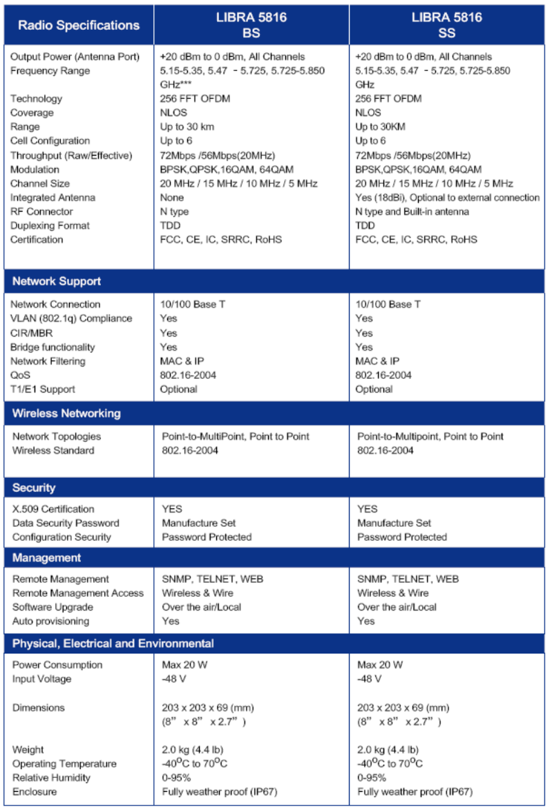
Specifications
Note: QAM64 with TX power 17dbm has the optimum performance.

LIBRA 5816 Quick Start Guide
28 LIBRA 5816 Series User Manual
Getting Started
Introduction
The contents in this chapter are provided only for qualified professional installation technicians for
reference.
Warning
All antennas and devices must be installed by professional installation technicians who are
familiar with such installation
Attention: It is recommended to always use a lightning arrester in the installation process.
Before the field installation of the device, the user shall work out network planning, make construction
preparations and finish the device debugging work. The network planning is used to describe the
whole system including the link budget, detailed list of required devices, LIBRA 5816 device, and
installation positions of antennas, wiring route, device parameter settings and other network
requirements. (GIL will provide network planning and field preparation support. Contact our sales
agent or access http://www.gil.com.tw for further information about the service and charges). Doing
network planning shall include the inspection of the installation field, checking the feasibility of the
network planning and recording details. Installation technicians shall check final field preparations,
conduct field installation and device settings as well as field-testing of every unit in accordance with
the network planning document. Before device installation, a large amount of network planning and
preparations shall be done. The more sufficient the preparations are, the less field installation
problems there will be.
Installation process
Field Installation of the LIBRA 5816 Device
This section will discuss how to install, configure and test the LIBRA 5816 device in the field.
Pay attention to the following affairs before the field installation of the LIBRA device:
" All the devices shall be configured as per the instructions of Product Configuration
Network
planning
Field
preparations
Device
debugging
FieldinstallationLinktest

LIBRA 5816 Quick Start Guide
29 LIBRA 5816 Series User Manual
" All the field preparations must be completed.
" Ensure all the required tools and equipment are prepared.
Field Preparations
Field preparations include inspection of the actual field environment and carry out field preparations to
ensure proper installation of LIBRA devices. Though every field has its own specialty and uniqueness,
the following preparations are necessary.
1. Acquire or work out a field installation plan. The planning shall include the installation position of
the LIBRA device, which kind of LIBRA device to be selected as well as the parameters of the
LIBRA device needed to be set.
2. Check cable connectivity before installation and the turning radius of the cable shall not exceed
the recommended radius.
3. Ensure there is enough space to keep proper ventilation.
4. Ensure AC power and Ethernet access can be used.
5. Check the predetermined installation position of the LIBRA device to ensure:
" The installation structure is reasonable.
" There are no barriers in the LOS link and the Fresnel zone. Owing to the extraordinary
non-LOS transmission property of OFDM, this requirement may not be as strict as that on
other systems.
" The installation position of the LIBRA device is reasonable.
6. Check the wiring route and cable inlet/outlet to ensure their usability.
Tools and Equipments
The following tools and equipment are a must:
1.Standard toolkit 7.Testing equipment, PDA with serial port cables and power
supply
2.An electric drill and burr drills 8.LIBRA device
3.Waterproof material 9.LIBRA installation parts
4.Ladder 10.Cables: Category 5 cable for outdoor and AC power line
5.Compass or GPS satellite positioning
devices 11.User acceptance form and installation records (optional)
6.Binoculars
LIBRA 5816 Quick Start Guide
30 LIBRA 5816 Series User Manual
LIBRA 5816 Installation Procedure
" Caution
Before energizing the LIBRA device, first connect the device to RJ-45 interface of the power
supply plug-in marked with “OUT”, and then insert the AC power line with the plug-in into the
AC power to energize the LIBRA device.
Warning
When connected to an Ethernet device, do not insert the RJ-45 interface for Ethernet cable to
the interface of the power supply plug-in marked with “OUT” as the interface is used to
energize the LIBRA device, which may damage the external Ethernet device.
When configuring LIBRA 5816 device, you need to assembly parts, find the proper installation
position, configure device parameters as well as detect the wireless link quality.
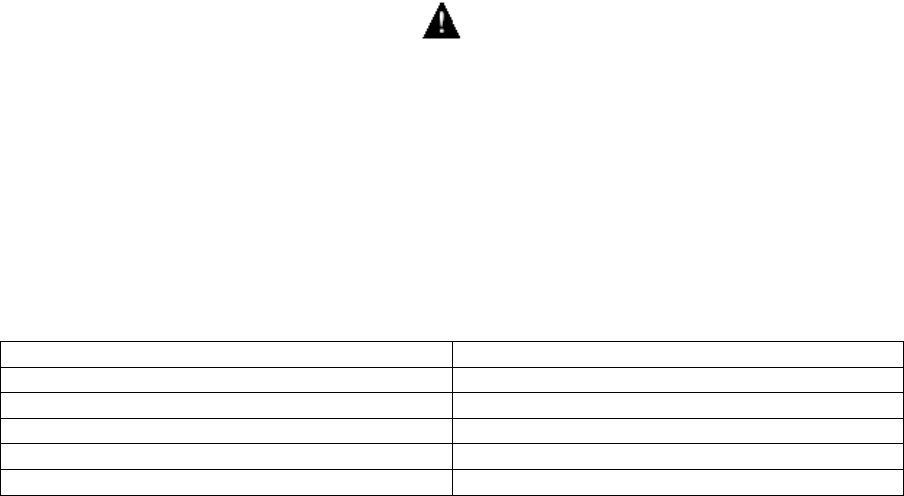
Mounting Instruction
LIBRA 5816 is designed to be mounted on pole. Below is assembly detail for mounting.
1. Enclosure 7. Mounting bracket clamp back
2. Trachea 8. Mounting clamp bolts
3. Bolt eye 9. Mounting Bracket Unit Anchor
4. Bolt 10. Water proof Ethernet socket
5. Bolt 11. RF connector
6. Mounting bracket clamp front
LIBRA 5816 Quick Start Guide
31 LIBRA 5816 Series User Manual
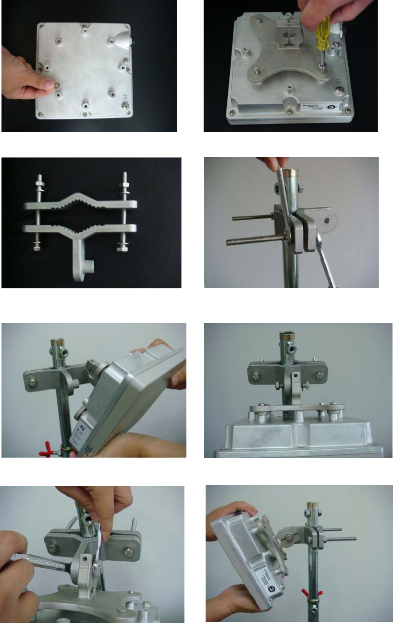
Assembling LIBRA unit
1. Assemble the bracket clamp which has not be connected to the LIBRA unit to the mounting rod,
as shown in Items 6, 7, 8 in the above drawing, adjust the screw to the extent that it can be
screwed by hand so as to adjust the direction of the antenna.
2. Mount the rear panel bracket to the rear of the LIBRA 5816 device with the screw marked Item 4
in the above drawing and fasten it. Assemble the required parts.
Attention: When mounting the clamp, be sure that the power/data interface of the LIBRA unit
or N-type antenna interface is at the lower end of the LIBRA unit to connect Category 5 data
cable for outdoor use, which will be waterproof.
3. For BS and LSS with separate antennas, connect the antenna directly to the device.
4. Adjust the antenna (integrated antenna or separate antenna) to make it point in the required
direction.
5. For devices adopting the directional antenna, if it is necessary to adjust the angle of pitch, the
antenna surface shall be turned towards directly to the corresponding unit as much as possible.
6. Slightly fasten the screw to enable the LIBRA unit to remain at the properly-adjusted position.
LIBRA 5816 Quick Start Guide
32 LIBRA 5816 Series User Manual
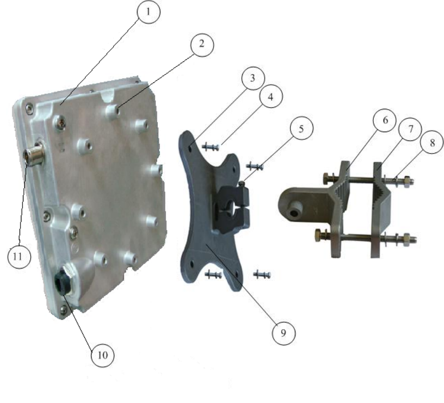
Connecting to LIBRA device
1. Use waterproof antenna cable without connector modification or transform on BS and SS.
2. Before screwing the cable connector, make sure the device is power-off.
3. After screwing cable connector on the device’s (BS or LSS) tight, use silicon or heat shirk tubing
to cover them is recommended.
4. All antenna accessories should be installed with device (BS or LSS) by an installer who has
trained professional.
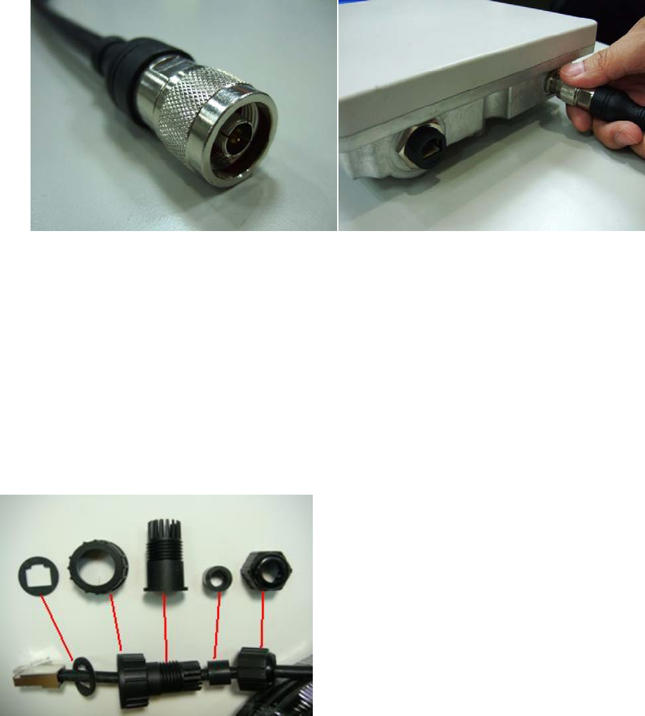
5. Insert one end of Category 5 cable for outdoor use into the waterproof installation assembly.
6. Connect the end of Category 5 cable inserting into the waterproof installation assembly to the
power/Ethernet interface of LIBRA device, and then connect the waterproof installation assembly
to the interface, screw and fasten the assembly.
7. Insert RJ-45 interface at the other end of Category 5 cable into “OUT” socket of the power plug-in.
8. Connect “IN” socket of the power supply plug-in to PC or Ethernet with a network cable.
9. Connect one end of AC power line to the AC interface of the power supply plug-in and connect
the other end to the AC power supply socket.
Attention: take necessary waterproof measures properly after completing all the above
installation and cable connection work. Bind anti-aging tape and waterproof that required
positions appropriately to protect devices from being damaged due to water ingression into
cables or damping of interfaces.
LIBRA 5816 Quick Start Guide
33 LIBRA 5816 Series User Manual
Device configuration and link test
1. Connect the portable computer to LIBRA device. (See Product Configuration).
2. If device parameters are not set beforehand, it is necessary to set key parameters such as center
frequency of devices etc.
3. Test the link state of the device and observe RSSI value and CINR value indicated in the device
menu.
4. If the link test results are satisfying, carry out the following sixth step directly.
If such results are not satisfying, first need to adjust the antenna direction by making use of
multipath transmission. If the adjustment effect is still unsatisfying, it is necessary to find another
installation position with good sight distance until such results are satisfying.
5. If failures remain unsolved, refer to the troubleshooting guidance. See Troubleshooting Table.
6. Keep adjusting the antenna position to achieve the optimum link test effects.
7. After acquiring the optimum link test effects, fasten the mounting parts firmly to fix the device.
Network connection test
Test computers at two ends of the link on their communication quality through the wireless link
after completing the above operations.
1. Contact the network operation centre (NOC).
2. Ping the corresponding NOC from the SS end.
3. Ping the corresponding SS from the NOC end. The SS may be “seen” in the network in a
successful ping test.
4. Connect the Ethernet port of SS to the LAN of the user end or to the user’s PC.
5. Ping the corresponding NOC from the LAN of the user end or from the user’s PC.
6. Transmit some large test file from the NOC port to the corresponding PC or other IP devices at
the corresponding LAN with FTP.
7. Test the file transmission rate from two ends.
Safety precautions regarding installation
Complete the installation through the following works.
1. Protect interfaces of all cables and waterproof outdoor cables.
2. Sort out all the packing boxes, cables and other materials.
3. Record the installation information listed below as per the requirements of the network service
provider (NSP):
" Link distance
" Installation site position (GPS coordinates)
" LIBRA device parameter setting
" Statistics of link quality
" Antenna cable configuration
" LIBRA device model, serial number, MAC address, IP address and IP net mask code.
" Password of LIBRA device
" Antenna azimuth (angle).
4. Demonstrate the device operation to the user to prove the installation work is completed and
further demonstrate good communication effect, data upload and download via the installed
wireless link.
The user signs his (her) name on the acceptance report to confirm the link quality.
LIBRA 5816 Quick Start Guide
34 LIBRA 5816 Series User Manual
z Mounting procedures step by step
1 2
3 4
5 6
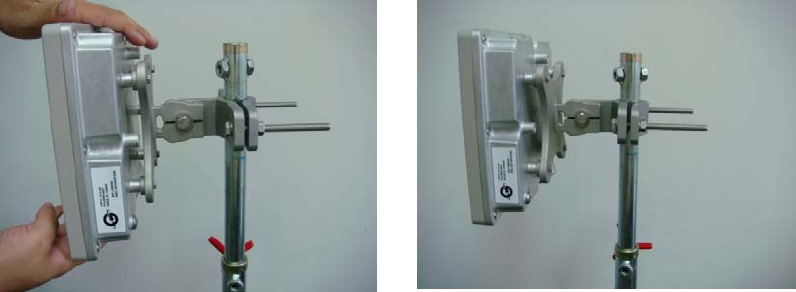
LIBRA 5816 Quick Start Guide
35 LIBRA 5816 Series User Manual
7 8
9 10

LIBRA 5816 Quick Start Guide
36 LIBRA 5816 Series User Manual
LIBRA 5816 Quick Start Guide
Initial Configuration
Once you have installed and set up the physical equipment for both the LIBRA 5816 base station and
subscriber station, you will need to configure both units so that they can connect to each other.
You do not need to configure your equipment to begin service at this time.
Your main focus at this stage is to make certain that all network hardware is working properly.
We recommend that you first set up your LIBRA 5816 base station, and then set up your subscriber
station.
For the initial PTP or PTM installation, the following points are for the quick installation basic
knowledge:
1. Connection Confirmation
2. LIBRA 5816 Web Login Access
3. Basic WiMAX Configuration/Link Status Check
4. BS/SS Key Configuration
4.1 IP configuration
4.2 RF Configuration
NOTE:
A. LIBRA 5816 is based on “plug & play;” connection between BS and SS is established by matching
radio frequency, bandwidth and modulation.
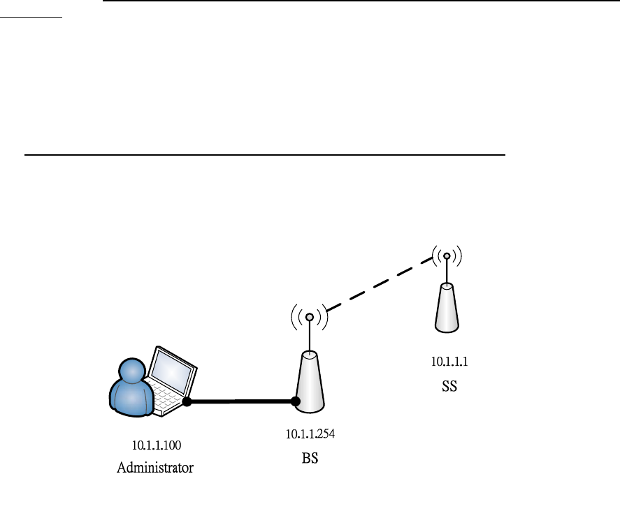
Default configuration of these numbers:
a. BS IP address: 10.1.1.254, SS IP address: 10.1.1.1
b. Frequency: 5800000 KHz
c. Bandwidth: 10 MHz
Following the default configuration is recommended. If user wants to modify the above
configurations, please see the section 4.BS/SS Key Configuration on page 42.
B. While testing for BS and SS, uninstalling or suspending any Anti-Virus software as well as the
Firewall of PC/laptop is recommended.
C. While reading Quick Start Guide, please be aware of the following word types represented as:
a. Emphasis: Italic font with underline:
b. DOS Command: Italic font of text
c. Web UI Command: Italic and bold font of text
d. Windows Command: “Italic, bold font of text with quotation marks”
e. Characters: “text with quotation marks”
LIBRA 5816 Quick Start Guide
37 LIBRA 5816 Series User Manual
1. Connection Confirmation
A. Antenna
LIBRA 5816 BS and N type SS need to be mounted on external antenna for working under
normal status. Please remember that mounting antenna on BS and N type SS before the
power-on.
B. Power-On Status
The initial configuration of LIBRA 5816 BS and SS from manufacture has reliable settled for
normal connection. They can auto-communicate each other after power-on.
C. IP configuration
C.1 PTP Network System:
Default IP address configuration, 10.1.1.254 to BS and 10.1.1.1 to SS, respectively. To
configure the PC’s or Laptop’s IP which is not in conflict with BS and SS. As the example
they are set as: IP address: 10.1.1.100
Netmask: 255.255.255.0
Then click “Start”, “Run”, and then type “cmd” for running DOS mode. Enter ping to
confirm the connection:
\>ping 10.1.1.254
\>ping 10.1.1.1
LIBRA 5816 Quick Start Guide
38 LIBRA 5816 Series User Manual
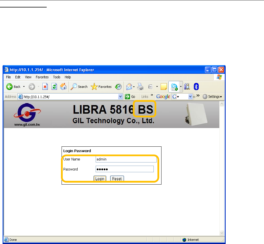
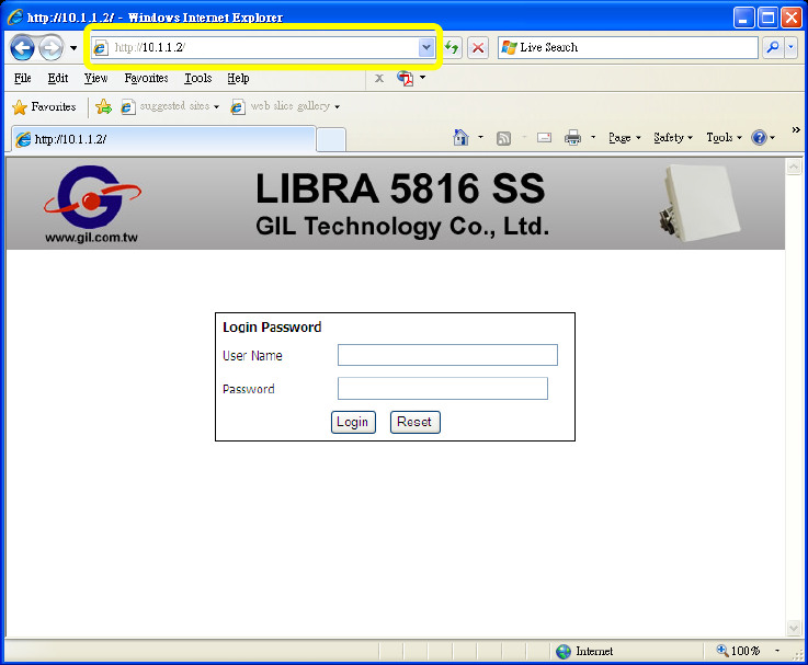
2. LIBRA 5816 Web Login Access
Default IP address is 10.1.1.254 to BS and 10.1.1.1 to SS, and default username and password
are both “admin”.
For login access, please follow those steps as below in order:
1. Open Web browser IE.
2. Enter correct IP address of BS or SS.
3. Enter “admin” in the blank of User Name and Password.
4. Click Login to access Web Control User Interface.
LIBRA 5816 Quick Start Guide
39 LIBRA 5816 Series User Manual
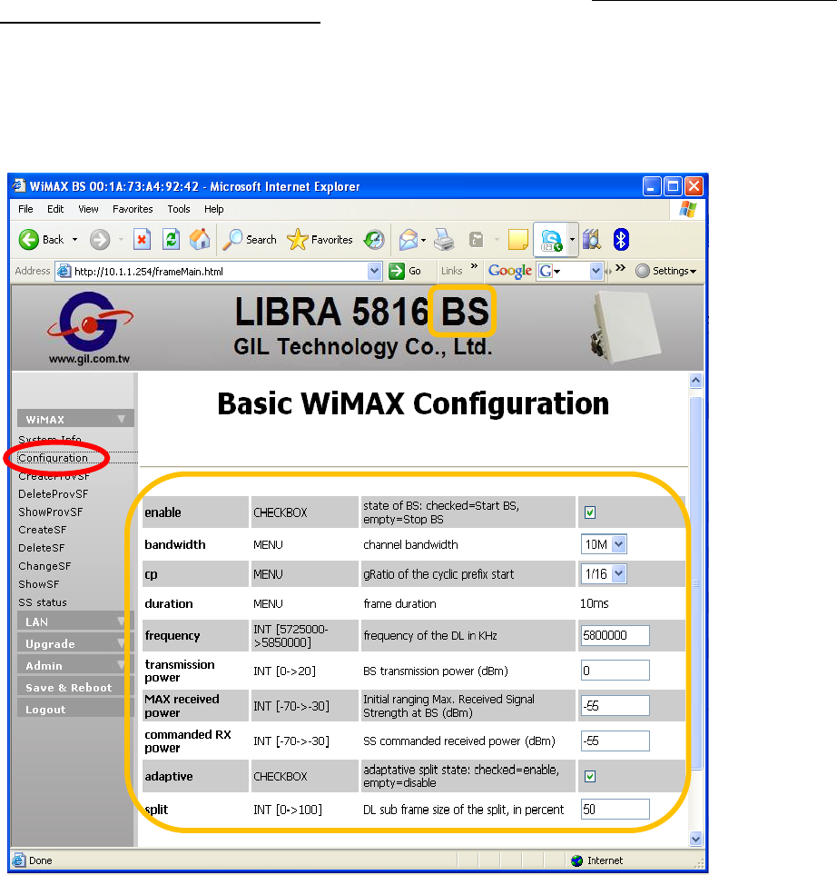
3. Basic WiMAX Configuration/Link Status Check
This section is for the check of default configuration and link status. Without necessity, please do
not modify those below configuration.
A. Base Station
A.1 Configuration Check:
1. Open Web browser to access 10.1.1.254 for Web UI of BS
2. Click WiMAX/Configuration on the left side of the page and then the WiMAX RF
configurations of the factory default are shown as the screen:
LIBRA 5816 Quick Start Guide
40 LIBRA 5816 Series User Manual
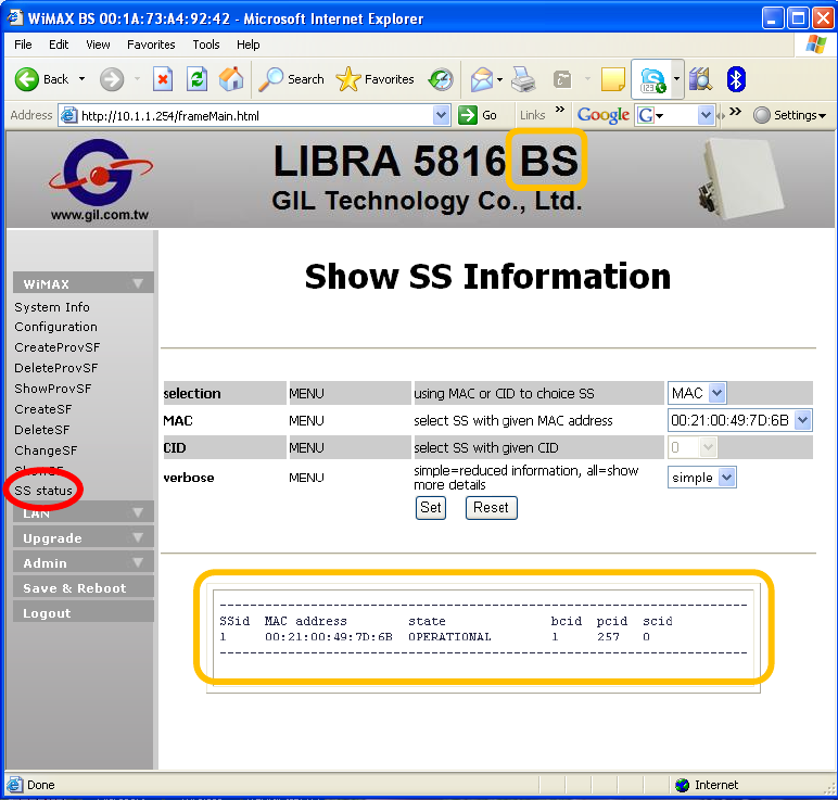
A.2 Link Status Check:
1. Click WiMAX/SS status on the left side of the page.
2. Click Set, the link status is shown as below with verbose set as “simple”. The screen shows
the ssid, MAC address, etc of SS which connects with BS.
LIBRA 5816 Quick Start Guide
41 LIBRA 5816 Series User Manual
B. Subscriber Station
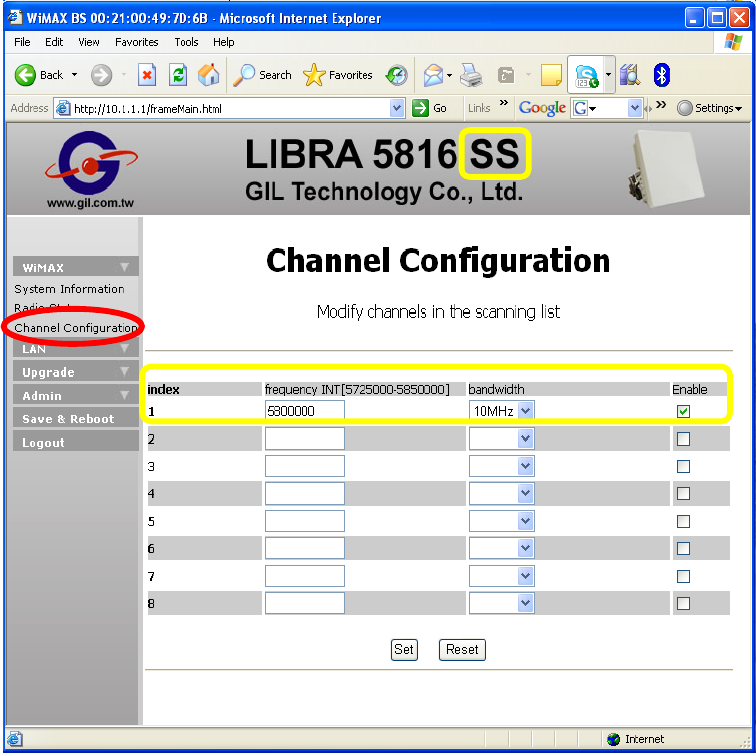
B.1 Configuration Check:
1. Open Web browser to access 10.1.1.1 for Web UI of SS
2. For checking default configuration of SS, please click WiMAX/Channel Configuration.
LIBRA 5816 Quick Start Guide
42 LIBRA 5816 Series User Manual
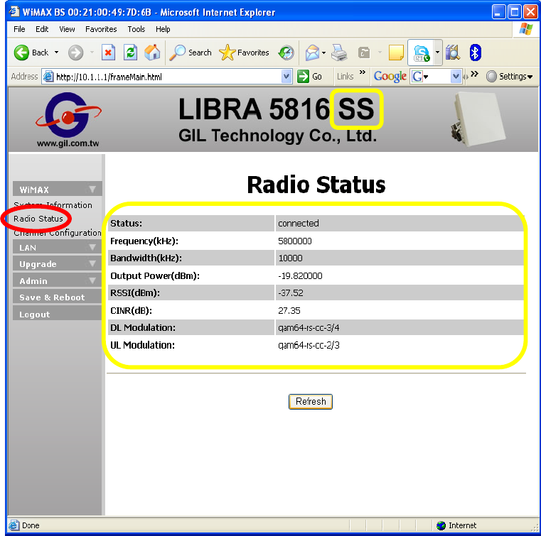
B.2 Link Status Check:
Click WiMAX/Radio Status, and then screen shows RF link status of SS.
LIBRA 5816 Quick Start Guide
43 LIBRA 5816 Series User Manual
4. BS/SS Key Configuration
4.1 IP Configuration
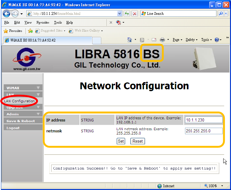
A. Base Station
1. Open Web browser to access 10.1.1.254 for Web UI of BS.
2. Click LAN/ LAN Configuration on the left side of the Web.
3. For example, entering new IP address 10.1.1.230 in blank.
4. Click Set and then follow the guide message to click Save & Reboot
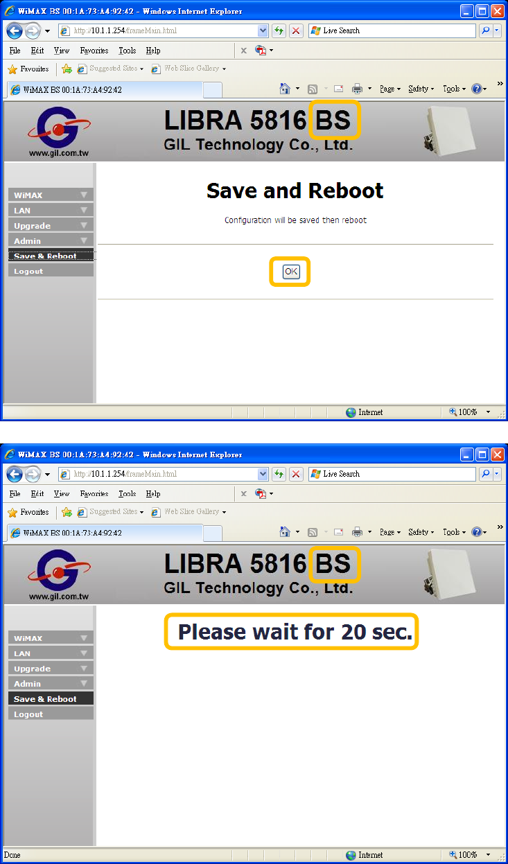
LIBRA 5816 Quick Start Guide
44 LIBRA 5816 Series User Manual
5. Click OK, and then wait for 20 seconds.
LIBRA 5816 Quick Start Guide
45 LIBRA 5816 Series User Manual
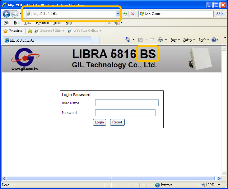
6. To enter new IP address in blank of browser for BS login access.
LIBRA 5816 Quick Start Guide
46 LIBRA 5816 Series User Manual
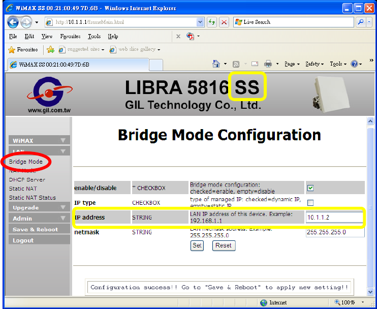
B. Subscriber Station
1. Open Web browser to access 10.1.1.1 for Web UI of BS.
2. Click LAN/ Bridge Mode on the left side of the Web.
3. For example, entering new IP address 10.1.1.2 in blank,
4. Click Set, and then follow the guide message to click Save & Reboot.
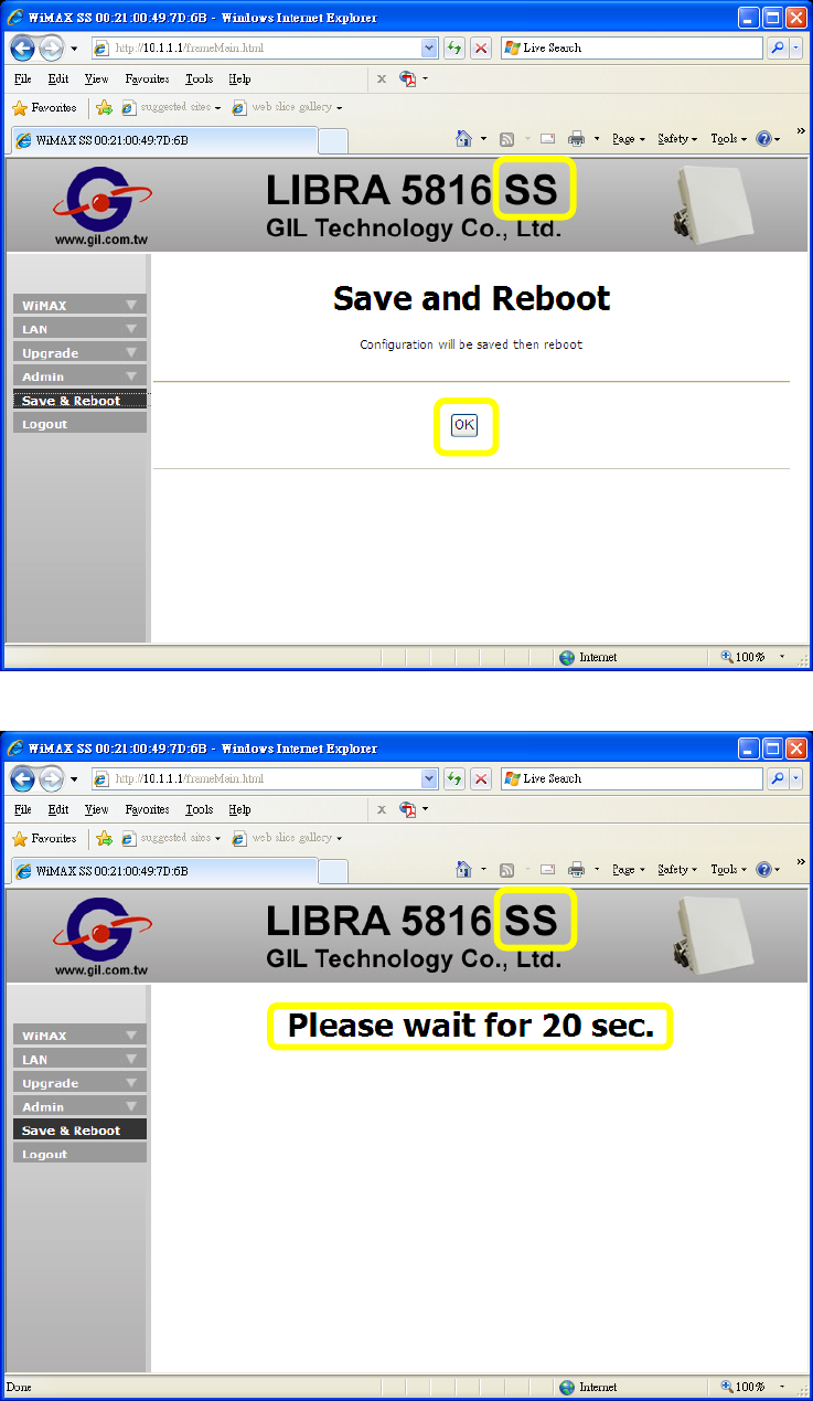
LIBRA 5816 Quick Start Guide
47 LIBRA 5816 Series User Manual
5. Click OK, and then wait for 20 seconds.
LIBRA 5816 Quick Start Guide
48 LIBRA 5816 Series User Manual
6. To enter new IP address in blank of browser for SS login access.
LIBRA 5816 Quick Start Guide
49 LIBRA 5816 Series User Manual
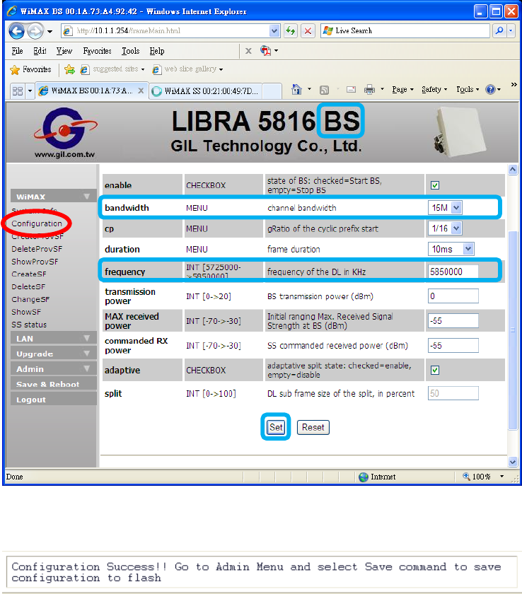
4.2 RF Configuration
A. Example: Modify Bandwidth and Radio Frequency.
Base Station
1. Open Web browser to access 10.1.1.254 for Web UI of BS.
2. Click WiMAX/Configurations on the left side of the Web.
3. Make bandwidth as 15MHz, frequency as 5850000KHz.
4. Click Set.
5. After click Set, please follow the guide message to save.
LIBRA 5816 Quick Start Guide
50 LIBRA 5816 Series User Manual
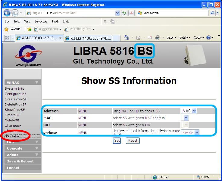
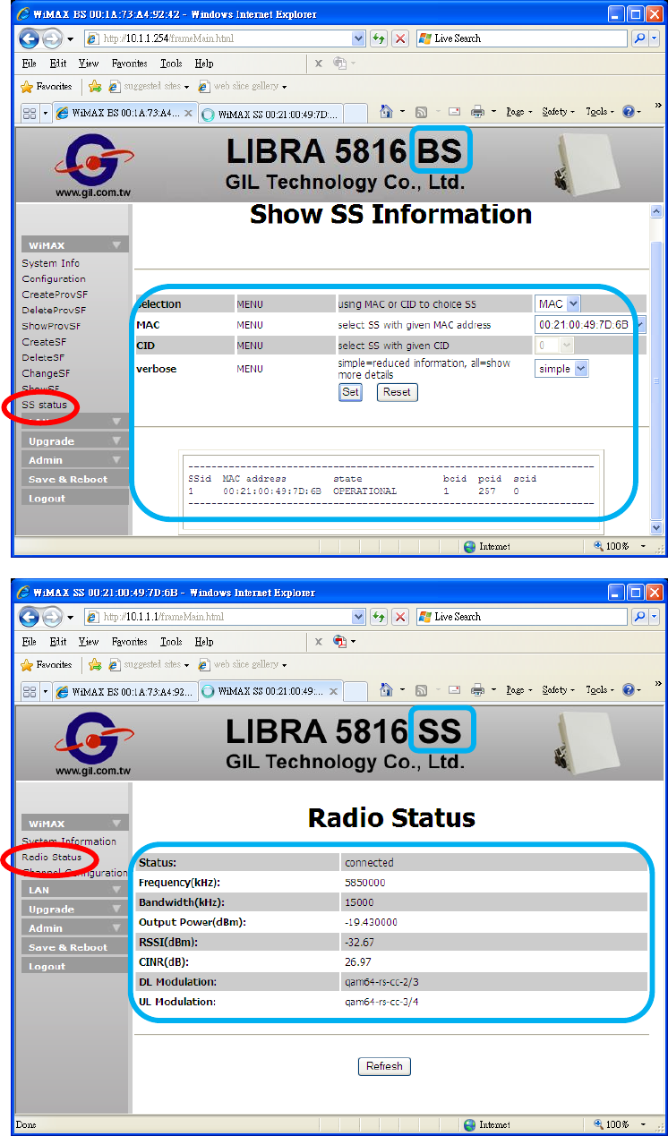
6. Click SS status, because of RF specifications of BS has been changed, thus there has no
SS is connecting with BS now.
LIBRA 5816 Quick Start Guide
51 LIBRA 5816 Series User Manual
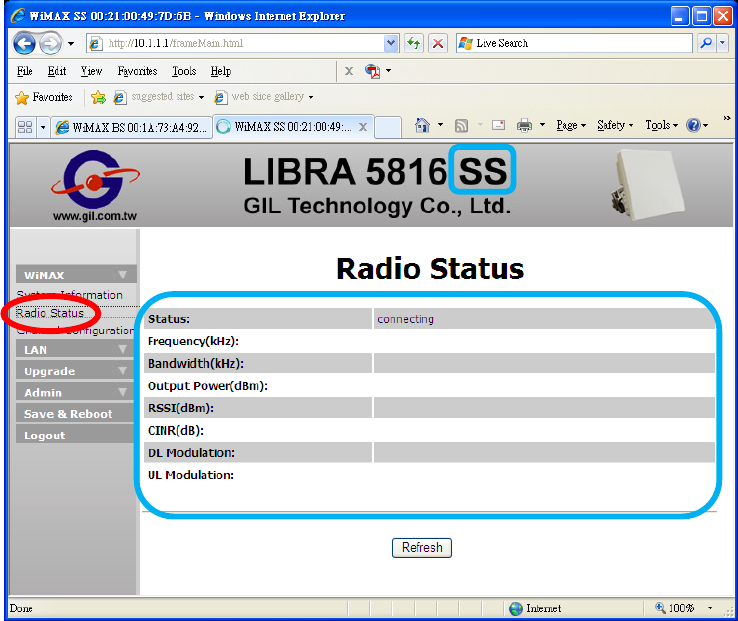
Subscriber Station
7. Open Web browser to access 10.1.1.1 for Web UI of SS.
8. Click WiMAX/Radio Status on the left side of the Web. There has no RF information of SS
before the connection established.
LIBRA 5816 Quick Start Guide
52 LIBRA 5816 Series User Manual
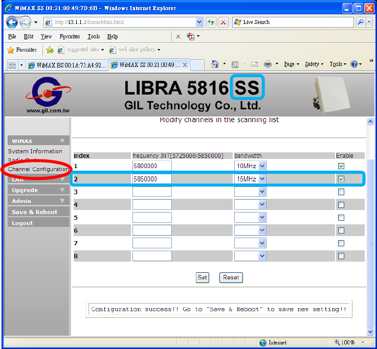
9. Click WiMAX/Channel Configuration.
10. Adding index 2. of scan list, frequency as 5850000KHz and bandwidth as 15MHz for
mapping RF specifications of BS. And then mark the check box for enable SS to scan this
channel.
11. Click Set, and then follow the guide message to click Save & Reboot.
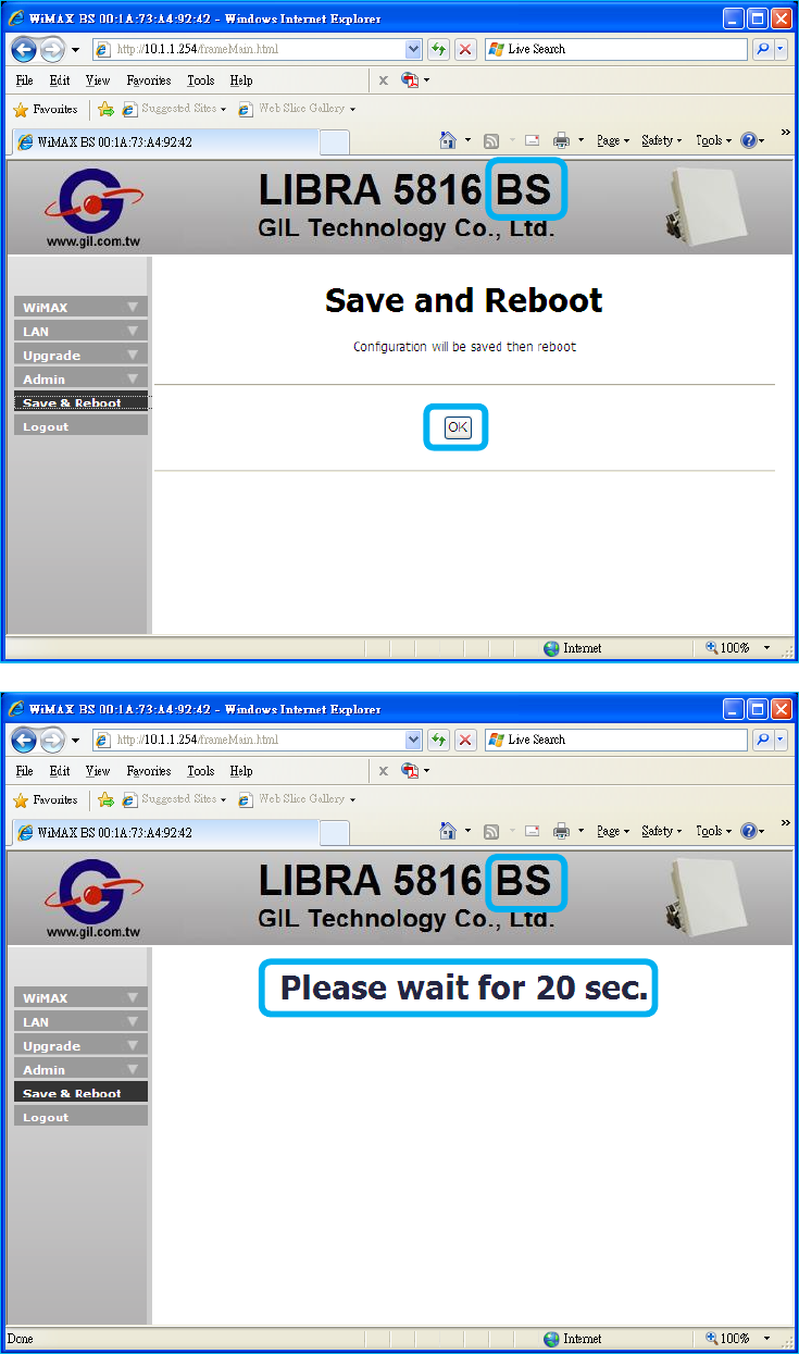
LIBRA 5816 Quick Start Guide
53 LIBRA 5816 Series User Manual
12. Click OK and then wait for 20 seconds.
LIBRA 5816 Quick Start Guide
54 LIBRA 5816 Series User Manual
13. Repeat the step 6 and 7 to check link status and RF information between SS and BS.

LIBRA 5816 Quick Start Guide
55 LIBRA 5816 Series User Manual
LIBRA 5816 Quality of Service Configuration Guide
QoS Configuration Demo
Abbreviation:
BE Best Effort
BS Base Station
DL Downlink
nrtPS non real time Polling Service
rtPS real time Polling Service
SF Service Flow
SFC Service Flow Configuration
SS Subscriber Station
UGS Unsolicited Grant Service
UL Uplink
Method:
1. Static SFC –
a. SFCs are storable in BS.
b. They are not real-time executed. SS should be restarted or repowered-on after
SFs are set.
c. UL and DL SFs should be coexistent.
Related command: CreatProvSF, DeleteProvSF, ShowProvSF
2. Dynamic SFC –
a. SFCs will be cleared after BS rebooted or repowered on.
b. It is real time executable, the SFCs work immediately.
c. There has default “Best Effort” of DL.
Related command: CreatSF, DeleteSF, ChangeSF, ShowSF

LIBRA 5816 Quick Start Guide
56 LIBRA 5816 Series User Manual
Before SFC Configuration
All items of those related command have their own definition as below:
MAC Media Access Control address of the SS
BCID Basic Communication Identifier
SFID SF Identifier
direction DL or UL of the SF
maxrate Maximum data rate of the SF
minrate Minimum data rate of the SF
maxlatency Maximum latency of the SF
priority Traffic priority of the SF
scheduling QoS type selection
grant interval The grant period between SS and BS (UGS mode only)
polling interval The polling period between SS and BS(rtPS and nrtPS)
-classifier1~4 (Syntax definition and format instance)
any Defines this classifier that matched all packets. Format: any
priority Priority of this classifier, integer range is [0..255]. The highest priority is 255,
default values is 128. Format: priority:55
ethsa Ethernet source address. Format: ethsa:00:11:22:33:44:55
ethda Ethernet destination address. Format: ethda:00:1A:2B:3C:4D:5E
ipsa IP source address. Format: ipsa:192.168.10.68
ipda IP destination address. Format: ipda:192.168.10.33
spr Source port range. Format: spr:1230 – 1240
dpr destination port range. Format: dpr:1510 – 1520
dscprm Different Service Code Point range and mask. Format: dscprm:13:57:63

LIBRA 5816 Quick Start Guide
57 LIBRA 5816 Series User Manual
ipproto Protocol transported by IP datagram. Format: ipproto:17
ipv6fl Matches the lower 16 bits of IpV6 flow label(00001-FFFFF). Format: FFFFF
vlan-id VLAN id 1~4094. Format: vlan-id:2024
Note: Please be aware of the following word types represented as,
f. Emphasis: Italic font with underline:
g. DOS Command: Italic font of text
h. Web UI Command: Italic and bold font of text
i. Windows Command: “Italic, bold font of text with quotation marks”
j. Characters: “text with quotation marks”
LIBRA 5816 Quick Start Guide
58 LIBRA 5816 Series User Manual
DEMO-1: Ping Time Configuration
(UGS Mode)
Goal:
To modify the ping time shorter between BS and SS.
1- Static SFC
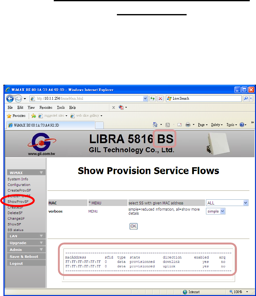
A. ShowProvSF:
1. Before provisioned SFC, click Ok to display default SFs information.
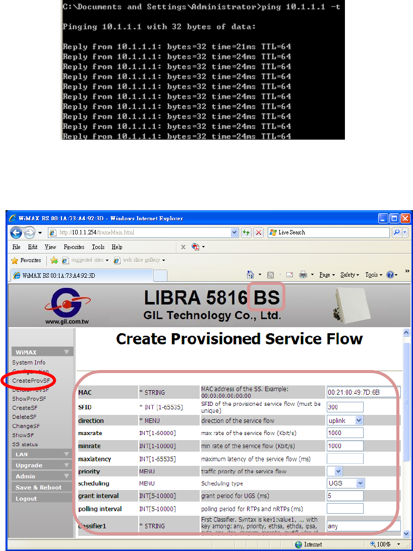
LIBRA 5816 Quick Start Guide
59 LIBRA 5816 Series User Manual
2. Then click “Start”, “Run”, and then type “cmd” for running DOS mode. Enter ping to check
default ping time:
\>ping 10.1.1.1 –t
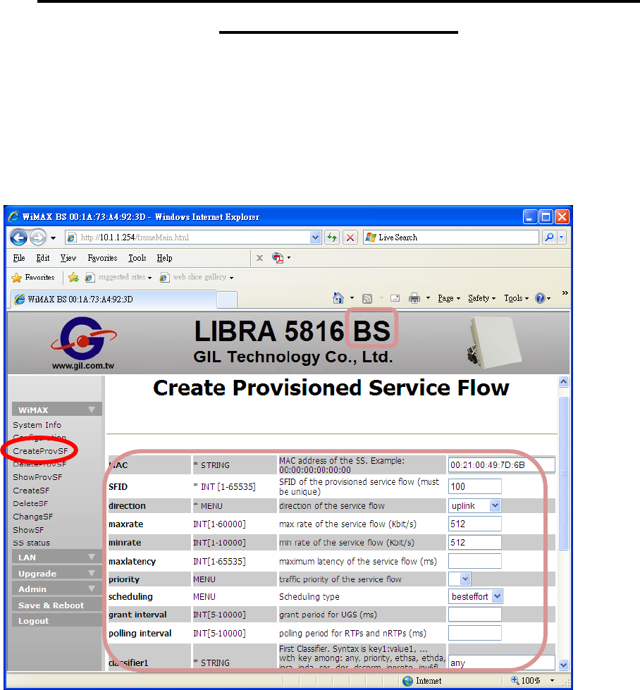
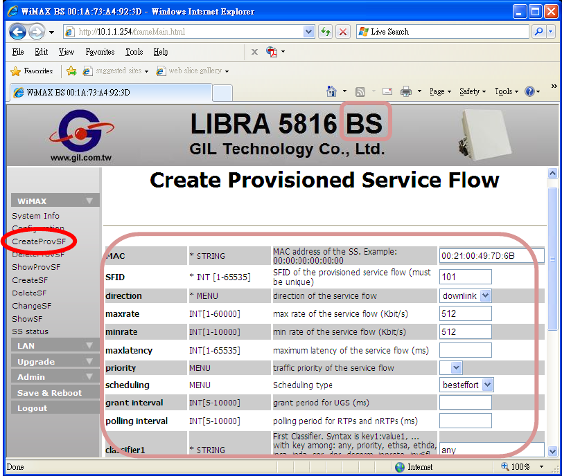
B. CreatProvSF:
1. Use SS MAC address as index, please refer to the below screen for creating
provisioned SFCs (Uplink and Downlink).
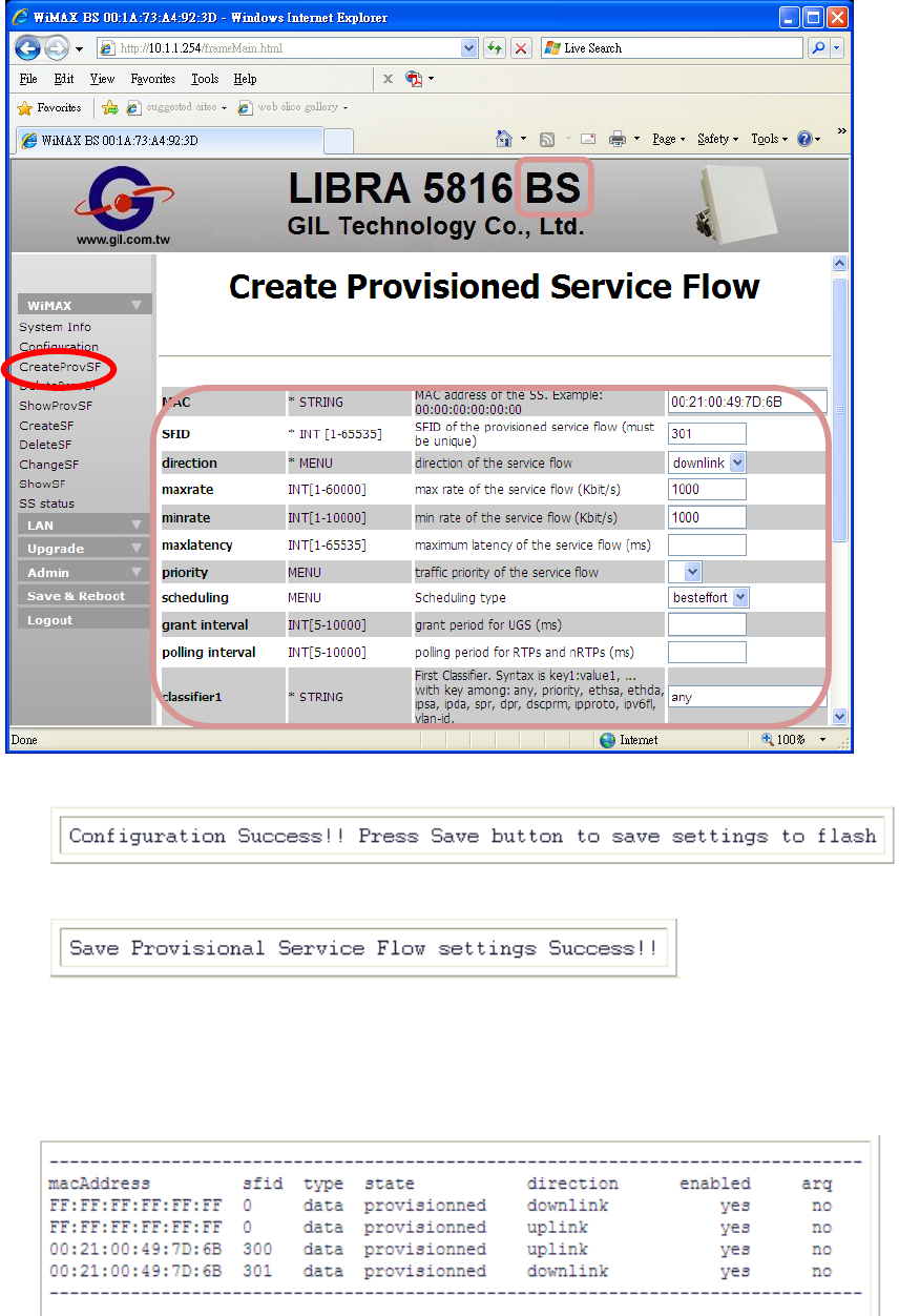
LIBRA 5816 Quick Start Guide
60 LIBRA 5816 Series User Manual
2. After click Set in BS.
3. And then click Save in BS.
4. SS must be rebooted or repowered-on so that the SFs are work.
5. Repeat step A. ShowProvSF to display provisioned information.
LIBRA 5816 Quick Start Guide
61 LIBRA 5816 Series User Manual
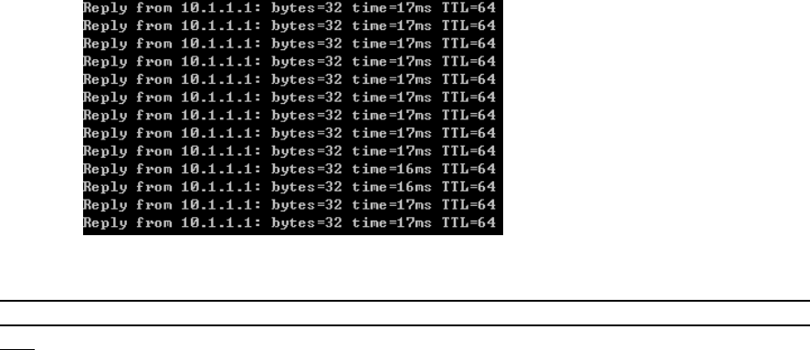
6. And then check the ping time.
The range of ping time between BS and SS is dependent on many conditions, such as
antenna selection, environment factors and another RF devices external influence,
etc.
LIBRA 5816 Quick Start Guide
62 LIBRA 5816 Series User Manual
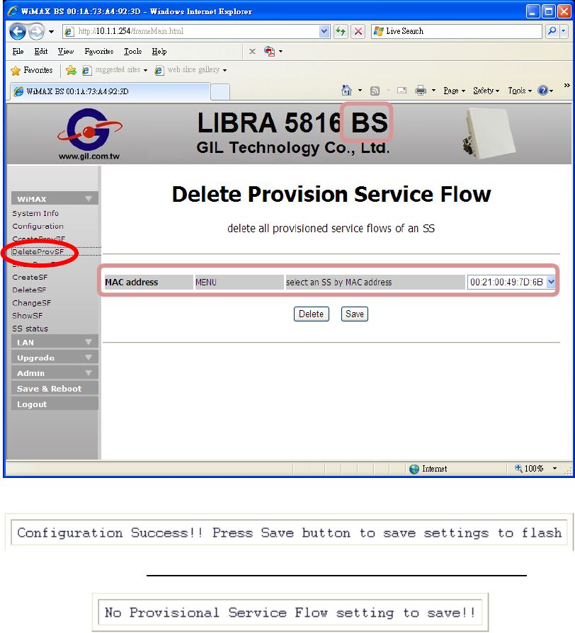
C. DeleteProvSF:
1. Use SS MAC address as index.
2. Click Delete.
3. Clikc Save, and all SFCs mapped this SS of BS will be removed.
LIBRA 5816 Quick Start Guide
63 LIBRA 5816 Series User Manual
2- Dynamic SFC
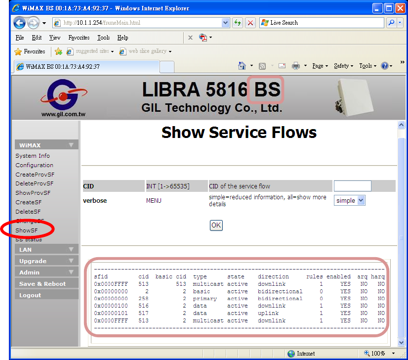
A. ShowSF:
Click Ok to display default SFs information.
LIBRA 5816 Quick Start Guide
64 LIBRA 5816 Series User Manual
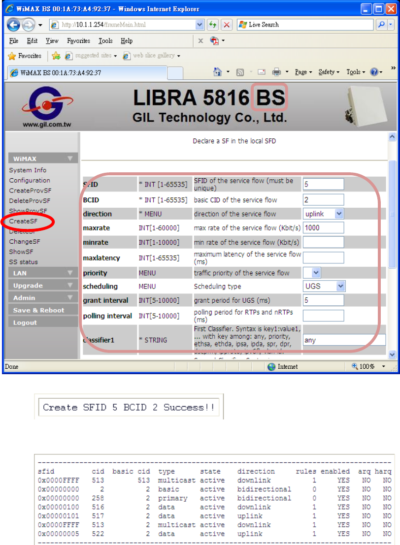
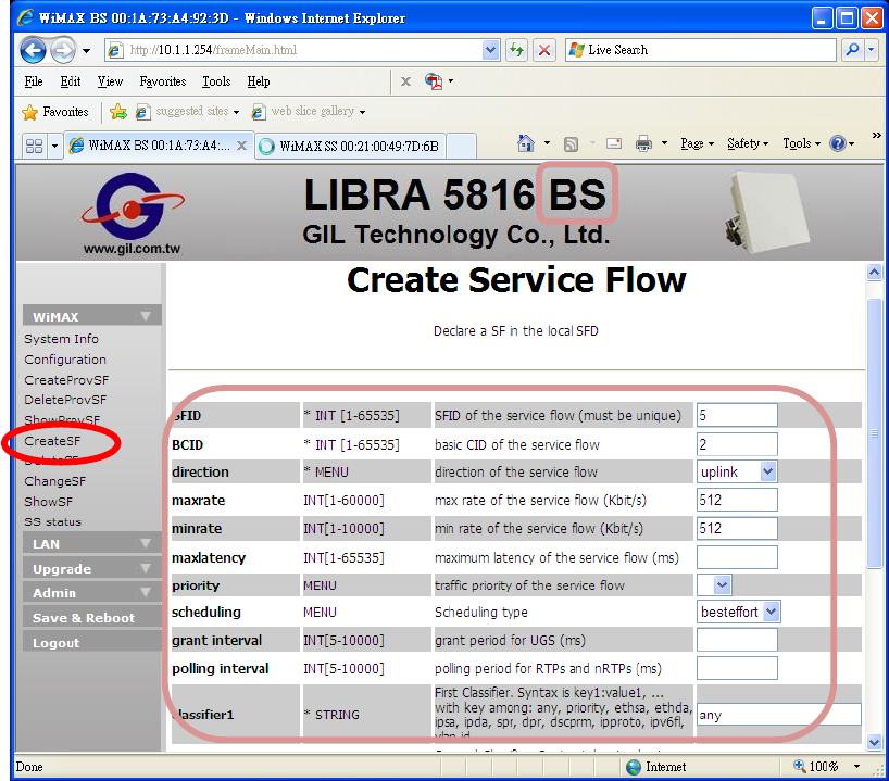
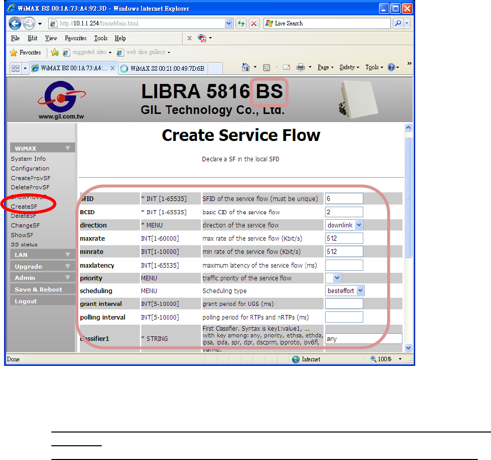
B. CreateSF:
1. As example, specifications of SFID, BCID, direction, maxrate, scheduling, grant
interval and classifier1 are configured as below: 2. Click
Set,
SFID
5 of
BCID
2 is
created.
3. Please review A. ShowSF for checking the new SF.

LIBRA 5816 Quick Start Guide
65 LIBRA 5816 Series User Manual
4. Click “Start”, “Run”, and then type “cmd” for running DOS mode. Enter ping, the
reply time should be improved between BS and SS.
The range of ping time between BS and SS is dependent on many conditions, such as
antenna selection, environment factors and another RF devices external influence,
etc.
LIBRA 5816 Quick Start Guide
66 LIBRA 5816 Series User Manual
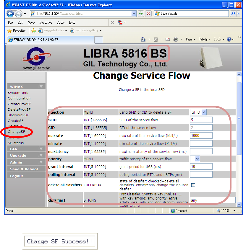
C. ChangeSF:
1. Select SFID or CID as index, and enter its number and new value.
2. Click Set, SF specification is changed.
3. Repeat section B.4 to verify the alteration of reply time.
LIBRA 5816 Quick Start Guide
67 LIBRA 5816 Series User Manual
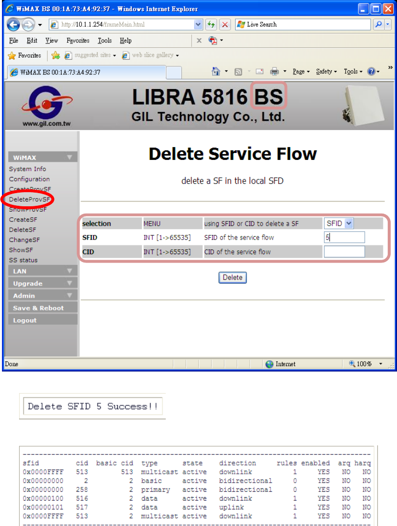
D. DeleteSF:
1. Select SFID or CID as index, and then enter its number.(Example: SFID 5)
2. After
click
Delete, SFID 5 is deleted.
3. Please review A. ShowSF for checking the SF list.
LIBRA 5816 Quick Start Guide
68 LIBRA 5816 Series User Manual
DEMO-2: Throughput Limitation Configuration
(Best-Effort Mode)
Goal:
To limit the data rates transmission of DL and UL between BS and SS.
1- Static SFC
CreateProvSF:
1. Use SS MAC address as index, please refer to the below screen for creating
provisioned SFCs (Uplink and Downlink).
LIBRA 5816 Quick Start Guide
69 LIBRA 5816 Series User Manual
LIBRA 5816 Quick Start Guide
70 LIBRA 5816 Series User Manual
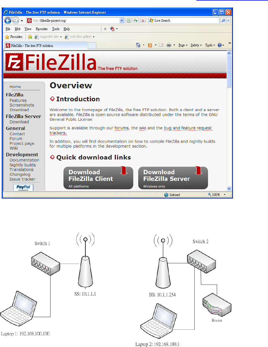
2. FTP software can verify the throughput per second simply. FileZilla Server and Client
are free and popular. They are available from the website: http://filezilla-project.org
3. Laptop1is installed on FileZilla Client, and Laptop2 on FileZilla Server.
LIBRA 5816 Quick Start Guide
71 LIBRA 5816 Series User Manual
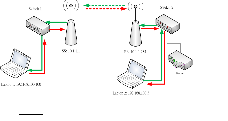
4. DL is a transmission from BS to SS (Green dotted line), and UL is contrary to DL (Red
dotted line). Therefore, laptop1 downloads from laptop2 is DL throughput (Green line),
and laptop1 uploads from laptop2 is UL throughput (Red line).
Throughput of DL and UL between BS and SS should be approximately limited to
512Kbps.
The file size unit of FileZilla is B (Byte), thus it is eight times the size of the b (bit).
LIBRA 5816 Quick Start Guide
72 LIBRA 5816 Series User Manual
2- Dynamic SFC
CreateSF:
1. Please refer to the below screen for creating SFCs (Uplink and Downlink)
LIBRA 5816 Quick Start Guide
73 LIBRA 5816 Series User Manual
2. Please review the static SFC steps, the same FTP software with the same network
structure.
Throughput of DL and UL between BS and SS should be approximately limited to
512Kbps.
The file size unit of FileZilla is B (Byte), thus it is eight times the size of the b (bit).

Troubleshooting
74 LIBRA 5816 Series User Manual
Troubleshooting
General principles
Proper management and maintenance can prevent the occurrence of many problems and discover
and handle problems as early as possible before problems become serious. The following methods
are recommended for regular maintenance.
" Establish regular maintenance log rules.
" Keep detailed records of failure points, symptoms, occurrence time and treatment methods.
" Follow up failure treatment results.
" Conduct planned link tests on a regular basis.
" Check the installation tower, antenna, ODU, cables and adapters on a regular basis,
especially after a bad weather.
" Test the system performance on a regular basis, as environment changes, normal wear and
cracks of the device may have an adverse impact on the system performance.
" Keep the integrity of system design when adding or changing a system. When adding a new
unit into the system, revise the network plan again to prevent problems. For example,
installing an extra antenna at the same place improperly will lead to self-interference of the
system.
" Save the records of all changes, especially relevant files of the adding unit, software and
hardware change, configuration and setting changes, as configuration error often leads to
other problems. Compare current record files with the original record files to analyze and
address failures.
Considerations on Regular Maintenance and Failure Treatment
1. Network Integrity: ensuring the integrity of the network is vital to the network performance and
reliability. If the network design is changed, the network operation will be affected. Fully acquaint
yourself with recent change of the network.
2. RF Link Quality: data communication depends firstly on good RF link. If you set up and maintain
high-quality RF link, you can ensure these links to bear high-speed data flow. If the quality of the
RF link deteriorates, as a consequence, the quality of data communications will deteriorate too.
3. Transmission Module: the module consists of three parts, namely, ODU generating signals;
antenna feed line including the cable, connector and oscillatory interference suppressor, antenna.
The faulty device may be found out through tests and replacements.
" To identify the state of the ODU unit, you may check the operating condition of the device on a
regular basis and observe its changes in RSSI value and Cinr value;
" To identify the state of the antenna feed line, you may use the integrated testing equipment to
test the properties of cables, connector and lightning arrester and replace parts when
necessary.
" To identify the state of the antenna, you may use the integrated testing equipment to test the
antenna and replace the antenna when necessary.
4. Proper Unit Configuration: the unit shall be properly configured as per the requirements of the
network plan. A configuration error may lead to communication failure or poor communication
performance. Adding a new unit in the system or making other changes to the system may need to
change the configuration.

Troubleshooting
75 LIBRA 5816 Series User Manual
Troubleshooting table
Symptoms Possible cause Corresponding measures
Bit error rate is too
high
Signal intensity is too low Adjust or replace the antenna or the cable.
Ensure there is no barrier in the LOS link of two
antennas.
Signal intensity is too
high Adjust the antenna azimuth.
Increase the distance between units to enhance
attenuation.
Reduce transmission power (Tx).
Interference Change the centre frequency
Increase the RF frequency
Change the antenna polarization mode
Increase the separation or change the antenna
position
Increase the antenna separation at the same
place
RF device damaged
(Tx/Rx) Conduct the bench test of RF devices
Replace RF devices
Antenna damaged Check whether the antenna is damaged.
Clean the antenna
Replace the antenna
Cable damaged Check whether the cable is damaged
Clean the cable
Replace the antenna
Connector damaged Check whether the connector is damaged
Replace the cable/connector
Temperature Detect whether the environment temperature is
too high or too low
Adjust the temperature properly
RSSI value or CINR
value is too low
Transmission distance is
too far Replace high gain antenna
Increase the transmission power
Reduce the modulation mode
RF device is damaged Conduct the bench test of RF devices
Replace RF devices
Antenna damaged Check whether the antenna is damaged.
Clean the antenna
Replace the antenna
Antenna not aligned Align the antenna again
Cable damaged Check the cable/connector
Clean the cable
Replace the cable/connector
RF parameter
configuration error Conduct a bench test over the RF parameter
settings
Configure the RF parameters again
No-clean fresnel zone Increase the antenna height
Change the antenna position
Remove the barrier
Power supply problems Replace different AC power
Test AC output power supply
Test power supply output of device

Troubleshooting
76 LIBRA 5816 Series User Manual
Symptoms Possible failures Corresponding measures
Packet loss rate is high Signal intensity decreases Check the LOS link of antennas
Check whether there are barriers in the
RF path.
Check the interference
Align the antenna again
Replace the antenna
Interference Change the centre frequency
Increase the transmission power
Change the antenna polarization mode
Increase the separation or change the
antenna position
Multipath interference Adjust antenna again
Chang antenna position
Temperature Detect whether the environment
temperature is too high or too low
Adjust the temperature properly
Communication failure
between units Configuration problems Check the following configurations:
z Whether Centre frequencies are
consistent.
z Whether IP address and netmask
code configuration are correct
Antenna or cable damaged Check whether antenna or cable is
damaged
Clean the cable and antenna
Replace the antenna or cable
Poor link quality Distance Check distance configuration of the
largest remote station
NLOS Check LOS between antennas.
Signal is absorbed Check barriers of LOS such as trees
Centre frequency Adjust the centre frequency and keep
away from the wireless interference from
other equipment
New configurations can
not effect Software update error Use FTP to load software mapping or
replace EPROM
Can not access main
configuration menu Password error
Contact Gil as the unit needs to be set
again.
The device does not
work Device failure Test the device and record the failure
results.
Software damaged. Update software
Power LED does not
light up
1. The power supply is
dead
2. POE Power failure
3. Device failure
1. Check whether the utility power is
normal or whether to use UPS for
power supply.
2. Replace POE power
3. Replace the faulty device

Troubleshooting
77 LIBRA 5816 Series User Manual
S
y
mptoms Possible failures Correspondin
g
measures
When pinging large
packet, the packet will
be expanded. When
pinging small packet, it
is normal
1. The link is obstructed
seriously.
2. Wireless signal is under
interference or
obstruction
1. Change the installation position to
ensure there is good LOS between
the base station and the user station
2. Find out and shutoff the interference
source; tune the antenna direction to
avoid the interference source or
reduce its impact; change the
installation point position to keep
away from the interference source;
adopt the physical insulation to avoid
the interference.
Packet loss is serious
1. The link is obstructed
seriously.
2. Wireless signal is under
interference or
obstruction
3. Too large user traffic
exceeds the bearing
capacity of the
bandwidth of the device
4. Under hacker attack.
1. Change the installation position to
ensure there is good LOS between
the base station and the user station.
2. Find out and shutoff the interference
source; tune the antenna direction to
avoid the interference source or
reduce its impact; change the
installation point position to keep
away from the interference source;
adopt the physical insulation to avoid
the interference.
3. Optimize the network and increase its
bandwidth.
4. Check the sector of the hacker to
identify the position of the subscriber
station the hacker is located and shut
off the device of this subscriber
station immediately, and then
negotiate with relevant entities.
No signal within the
normal coverage range 1. Serious obstruction
2. Device failure
3. SS version and BS
version is not consistent.
4. Frequency configuration
not correct.
1. Change the installation position to
ensure there is good LOS between
the base station and the user station.
2. Replace the device
3. Update the software version
4. Check the menu of the device to
make sure BS frequency and SS
frequency are consistent.
Troubleshooting
Separat
edeviceOutdoor
Ethernet
Lightning
Arrester
Outdoor
Ethernet
Lightning
Arrester
Power
adapter
Outdoor
Cate
g
or
y
5Cable
Ground
Point
Wall‐through
cablehole
Category
5cable
RF
Lightnin
g
Anten
na
RFcable
Ground
Point
Outdoor
Category5cable
Integrated
device
foroutdoor
use
Outdoor
Ethernet
Lightning
arrester
Outdoor
Ethernet
Power
adapter
Ground
p
ointWall‐through
cablehole
Category5cable
Appendix A:
Specifications for lightning protection of GIL Technology
In view of the specific characteristics in wireless device field installation and as per the requirements
of actual conditions, Gil Technology Company Limited hereby formulates this technical specification of
lightning protection of LIBRA5816 wireless device. In case the user fails to adopt this specification,
our company will not be liable for any wireless device damage or wireless link interruption
arising out of lightning strike to the device.
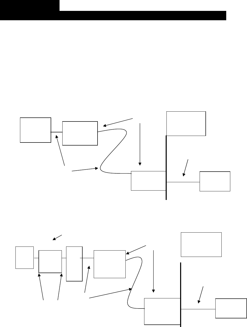
" Ensure that a properly grounded lightning rod has been installed on the iron tower or the
holding pole;
" Install an Ethernet lightning arrester outdoors at the position within 1.5m to the incoming inlet
or install an arrester in the indoor computer room to protect the indoor devices in the room.
" For integrated devices for outdoor use, install an outdoor Ethernet lightning arrester outdoors
at the position within 1.5m to the outdoor devices to protect wireless bridge equipment;
" For devices with separate antennas, install a RF feeder lightning arrester on the RF cable
to protect the high frequency circuit of the device; in the meantime, install a lightning arrester
on the outdoor Ethernet cable within 1.5m to outdoor devices;
" Ensure lightning arresters are properly ground