User Manual
G-scan2 User Manual
1
Contents
Chapter 1. Cautions and Warnings 3
Copyright Notice and Disclaimer 4
Introduction to G-scan2 6
Safety Warnings and Cautions 7
Warnings for environment protection 10
Chapter 2. Getting Started with G-scan2 11
Specifications 12
Parts and Components 14
Details of the base unit 23
Power supply to G-scan2 24
Rechargeable Battery 30
Connecting with the vehicle 32
Rear Pack Replacement 33
Chapter 3. G-scan2 Basic Operations 35
Main Menu and System Tools 36
Quick User Guide 39
Configuration 40
Utility 49
Internet Quick Update 65
Power Management 70
Recorded Data 71

G-scan2 User Manual
2
OBD-II 76
Vehicle Diagnosis 81
Diagnostic Functions 82
Maker Selection 97
Japanese Cars 100
Korean Cars 106
Measurement 120
Oscilloscope Function 121
Multi-meter Function 137
Simulation Function 143
Favorite 147
G-scan2 System Lock 151
Chapter 4. G-scan2 PC Utility Software 157
Installation and Removal 158
Main Menu 165
Software Update Online 167
Software Update Offline 175
Data Viewer 177
PC Utility Configuration 185
Network Printer Setup 190
Chapter 5. Appendix 192
G-scan2 Limited Warranty 193
Discard of Used Equipment 195

G-scan2 User Manual
3
1.1. Copyright Notice and Disclaimer
1.2. Introduction to G-scan2
1.3. Safety warnings and cautions
1.4. Warnings for environment protection
Chapter 1. Cautions and Warnings

G-scan2 User Manual
4
1.1 Copyright Notice and Disclaimer
Cautions and Warnings AA-1-1. Copyright Notice and Disclaimer
Thank you for purchasing G-scan2 supplied by GIT(Global Information Technology) Co., Ltd.
This manual contains information needed for using G-scan2.
We recommend you to read this manual and comprehend the provided functionality before start using
G-scan2 in order to get the maximum performance out of the product
Copyright Notice
G-scan and G-scan2 are copyrighted 2008-2013 by GIT Co., Ltd. All rights are reserved.
File manipulation, de-compilation, disassembly, reverse-engineering, alteration, use as a
reference tool for the purpose of developing a product with similar functionality, and re-distribution
in any form without the prior written consent of GIT Co., Ltd. is prohibited.
GIT Co., Ltd. owns the intellectual property including but not limited to patents, trademarks and
copyright contained in this user’s manual. No part of this manual may be photocopied, reproduced,
or translated to another language in any way without the prior written consent of GIT Co., Ltd.
Purchase of this user’s manual shall not be assumed as granting or transferring the rights to
utilize intellectual property of GIT Co., Ltd. contained in this manual.
Copyright Notice
By use of this product, you acknowledge that the product is provided "as is" and "with possible
faults, defects and errors" and that all use of the Product is at your own risk.
Even though the product has been extensively tested and evaluated, GIT Co., Ltd. cannot
guarantee it will work correctly as intended with every system in every vehicle. GIT Co., Ltd. will
do our best to fix any bugs and to bring enhancements to the product, but we specifically disclaim
any liability for damage to the car and yourself.
GIT Co., Ltd. reserves the right to change or modify the content of this instruction manual for both
technical and non-technical product enhancement without notice. This may include scan tool
graphic displays, vehicle coverage, supported functions and operating procedures. Hardware may
also be modified, altered or redesigned or may differ from the descriptions and illustrations
displayed in this manual.

G-scan2 User Manual
5
G-scan2 is originally designed not to show the emblems or trademarks of the car manufacturers
in the menu in order not to cause infringement of intellectual property rights of the car
manufacturers, therefore any attempt to alter or modify its software to show those emblems and
trademarks on G-scan’s screen is against the policy of GIT Co., Ltd therefore it shall be done at
user’s own risk and GIT Co, Ltd. shall not be held responsible.
G-scan2 User Manual
6
1.2. Introduction to G-scan2
Cautions and Warnings AA-1-2. Introduction to G-scan2
Functionality
G-scan2 is designed to maximize the product efficiency by helping the users fully utilize the
diagnostic and measurement functions with the user friendly interface and intuitive operations
Advanced Touch Screen Interface
Touch screen offers easy and intuitive selection of the menu or the desired function right from the
screen without the complexity of pressing the buttons
7.0” Color TFT LCD
Large scale 7” TFT LCD ensures readability with striking graphical display and friendly user
interface for better presentation of diagnostic information
Expandability through USB interface
Standard USB interface enables the product to host the new diagnostic devices that are going to be
developed in the future
Wireless Connectivity (WLAN)
The on-board Wi-Fi module enables the software update through wireless internet connection and
use of the network printer for direct printing
Large Capacity SD card
Large capacity the SD card accommodates the diagnostic programs and data, and offers sufficient
storage for user’s own database build-up
2100mA Battery
Rechargeable battery enables the use of the measurement functions without external power supply
and the diagnostic functions that need engine cranking without a power-cut

G-scan2 User Manual
7
1.3. Safety Warnings and Cautions
Cautions and Warnings AA-1-3. Safety Warnings and Cautions
This section contains warnings and cautions for safe and proper use of this product, therefore it is
recommended that every user should read this section carefully before using the product and make
sure that such warnings and precautions are well observed and comprehended.
Use G-scan2 only for the original purposes as it was designed for.
Keep G-scan2 within the specified storage temperature when not in use (See spec sheet)
Place the G-scan2 at a secured location and keep clearance with any moving part of the vehicle or
hazardous environment when using G-scan2 with the vehicle.
Use only the parts and accessories authorized by GIT.
Do not disassemble or dismantle the G-scan2 base unit in any case.
Beware that only the service personnel authorized by GIT is entitled to provide after-sales service
for G-scan2.
Supply stable power from the external source (using AC/DC adapter) when updating G-scan2
software (Operating System, Firmware and Application updates).
Use the power adapter and cables supplied by GIT only when supplying power from then external
source.
Make secure connections of all cables and connectors. Be careful not to let the DLC cable or
power cable gets disconnected while the G-scan2 is operating.
Observe the instructions of this user’s manual when replacing the rechargeable battery.
Do not use the rechargeable battery other than GIT supplies.
Do not disassemble the rechargeable battery in any case.
Do not put the rechargeable battery in the water and keep away from moisture.
Keep the rechargeable battery from the heat.
Warning
Dangerous consequences may arise, with the possibility of fire, death or serious injury to the user,
if the product is not handled properly as instructed below.
The user shall be fully liable for any direct or consequential damage or loss caused by not following
the instructions provided in this G-scan2 user’s manual.

G-scan2 User Manual
8
Do not apply physical impact to the rechargeable battery or pierce with a sharp object.
Do not put the rechargeable battery in the microwave oven or high-voltage container.
In case any smell, heat, distortion or discoloration is observed with the rechargeable battery, stop
using it. If such a symptom is witnessed when charging or operating, remove the battery from
the base unit.
Be careful not to put the rechargeable battery in reversed polarity.
Do not short-circuit the rechargeable battery terminals.
Do not connect the rechargeable battery terminals directly with the external power sources.
Do not put the rechargeable battery in fire or expose it to direct sun light.
Put G-scan2 base unit on a secure place and avoid unstable, inclined or slippery place.
Be careful not to drop the G-scan2 base unit.
Avoid humidity and dusts when storing and using G-scan2 in order to prevent electric shock or
fire.
Do not put heavy objects such as hand tools on the G-scan2 base unit.
Stow the parts and accessories that are not in use in the G-scan2 carry case.
Avoid following hazards for storing G-scan2.
- Too high or low temperature (See Spec sheet)
- Too high or low humidity (See Spec sheet)
- Exposure to direct sunlight
Be careful not to cause damages to the cables by heat from the engine or the moving parts in the
engine compartment when G-scan2 cable connection is made under the hood.
Securely tighten the screw lockers when connecting the DLC main cable to the G-scan2 base unit.
When supplying power from the vehicle battery, check the connection for correct polarity.
Do not carry the G-scan2 by holding the cables connected to the base unit.
Avoid physical impart and vibration when carrying G-scan2.
Caution
Dangerous consequences may arise, with the possibility of serious injury to the user and or
damage to the product, if the equipment is not handheld correctly as instructed below.
The user shall be fully liable for any direct or consequential damage or loss caused by not
following the instructions provided in this G-scan2 user’s manual.

G-scan2 User Manual
9
Do not put the SD card upside down when inserting to the base unit
Use only the AC/DC adapter that is supplied with G-scan2 when supplying power from AC source
Storing the rechargeable battery in a hot place may shorten its lifetime
In case battery liquid gets in the eyes, do not rub and wash them with fresh running water. And
see the doctor immediately
Use the stylus pen supplied as the basic accessory of G-scan2 when touching the screen. Use of
sharp or pointed object may cause serious and irrecoverable damage to the touch screen film and
the LCD
Keep LCD away from liquid or splash of water
Liquid Crystal may run from the broken LCD. Do not touch the LCD when it is broken, and be
careful not to get liquid crystal in the eyes or mouth. If contaminated by liquid crystal on the skin,
remove them immediately using soap and running water
Use soft fabric and alcohol to clean the surface of the LCD
Do not use volatile solvents other than alcohol when cleaning the LCD
Perform Touch Screen Calibration when the touched point is not coordinated correctly. The touch
screen needs zeroing when used for an extensive period of time
G-scan2 User Manual
10
1.4. Warnings for environment protection
Cautions and Warnings AA-1-4. Warnings for environment protection
When the product has been used up to its life-time and needs to be disposed, the rules and
regulations that the government of each country has set forth for material recirculation, wasted
electric/electronic product disposal or other related legal procedure shall be checked and followed.
When disposing the wasted product, please observe the warning message below.
Warning
When disposing G-scan2, do not dump it among the daily wastes. In many countries, it
either shall be approved by local authorities or recollected by the local distributor.
Disposal by burning or burying it underground without authorization is not generally allowed
in most of the countries.
Contact your local distributor to consult the proper procedure for G-scan2 disposal.

G-scan2 User Manual
11
2.1. Specifications
2.2. Parts and Components
2.3. Details of Base unit
2.4. Power Supply to G-scan2
2.5. Rechargeable Battery
2.6. Connecting to the vehicle
2.7. Rear Pack Replacement
Chapter 2. Getting started with G-scan2
G-scan2 User Manual
12
2.1. Specifications
Getting Started with G-scan2 AA-2-1. Specifications
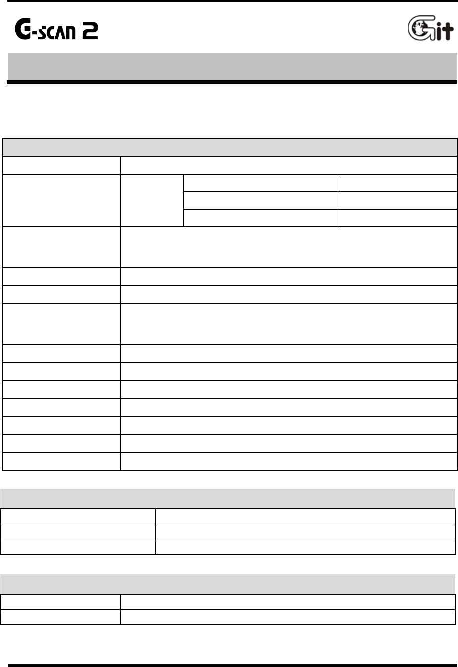
G-scan2 Base Unit
General Specification
Category Specifications
CPU Triple CPU
Main control Board ARM11@ 600MHz
Communication Board ARM9 @ 266MHz
Measurement Board ARM9 @ 266MHz
System Memory
Main Control Board: NAND Flash 128MB and SDRAM 256MB
Communication Board: NAND Flash 32MB and SDRAM 8MB
Measurement Board: NAND Flash 32MB and SDRAM 8MB
External Memory 16GB SD Card
LCD 7” TFT LCD (1024 X 600 pixel)
Input Devices
Touch Screen
Power, Enter and Esc keys
4 way directional keys , F1 ~ F6 function keys
Indication Lamps 3 Color LED
Sound Buzzer and speaker
Rechargeable Battery Li-Ion Polymer 2100mAh 1cell
Operating voltage 7 ~ 35V DC (10~35V for charging)
Housing Material PC + ABS resin with rubber shrouds
Dimension 230 X 146 X 72 mm (with VMI pack mounted)
Weight Approx. 1300g (with VMI pack mounted)
Connectivity
External COM port 1 X USB 2.0 standard (master) + 1 X mini USB (slave)
WiFi Module On-board
Blue Tooth On-board
AC / DC Power Adapter
Input Power 100 ~ 240V AC
Frequency 50 / 60 Hz
G-scan2 User Manual
13
VMI Pack (Optional)
Oscilloscope
Voltage Division 2 Channel Mode
400mV,
800mV,
2V,
4V,
8V, 20V, 40V,
80V,
200V, 400V
4 Channel Mode
4V,
8V,
20V,
40V,
80V,
200V, 400V
Vertical Resolution 10 bit
Sampling Mode Normal / Peak Mode
AC/DC Coupling Supported
Time Division
2 Channel Mode 100 ㎲, 200 ㎲, 500 ㎲, 1 ㎳, 2 ㎳, 5 ㎳, 10 ㎳, 20 ㎳,
50 ㎳, 100 ㎳, 200 ㎳, 500 ㎳, 1s, 2s, 5s
4 Channel Mode 200 ㎲, 400 ㎲, 1 ㎳, 2 ㎳, 4 ㎳, 10 ㎳, 20 ㎳, 40 ㎳,
100 ㎳, 200 ㎳, 400 ㎳, 1s, 2s, 4s
Digital Meter
Voltage 400 mV, 4V, 40V, 400V / Auto Range
Resistance 1Ω ~ 10 ㏁ / Auto Range
Frequency 1Hz ~ 10kHz / Threshold level : 2.50.5V
Duty Cycle
0.1% ~ 99.9% @ 1Hz ~ 100Hz
1.0% ~ 99.0% @ 100Hz ~ 1kHz
3.0% ~ 97.0% @ 1kHz ~ 3kHz
5.0% ~ 95.0% @ 3kHz ~ 5kHz
10.0% ~ 90.0% @ 5kHz ~ 10kHz
Pulse Width 10 ㎲ ~ 1,000ms
Simulation
Voltage Signal Output 0.0 ~ 5.0 V
Frequency Signal Output 1Hz ~ 999Hz (50% duty)
Actuator Control
Frequency Range 1Hz ~ 999Hz
Duty Range 1% ~ 99% @ 1Hz ~ 99Hz
10% ~ 90% @ 100Hz ~ 999Hz
Pulse Width Variable
G-scan2 User Manual
14
2.2. Parts and Components
Getting Started with G-scan2 AA-2-2. Parts and Components
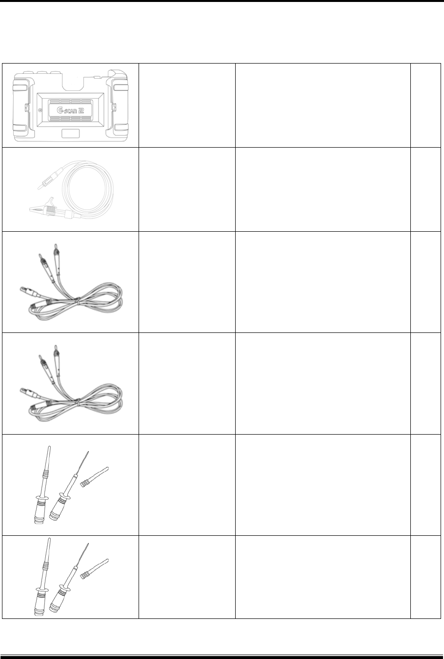
Basic Supplies
Part Part Number Description Q’ty
G1FDDMN029
(Blue)
G1FDDMN020
(Black)
Part Name: G-scan2 Base Unit
G-scan2 base unit with VMI module
Includes the battery and SD Card
1
A2MDT2SD16G
Part Name: SD Card 16GB
Provided included in the base unit.
A memory card that contains software
and data for diagnostic functions.
1
G1FZFCA001
Part Name: Cable – DLC Main Cable
The main cabled used for connecting
the G-scan2 base unit and the car’s
OBD2 connector.
1
A2MDK1CCRP5
Part Name: SD Card Reader
A USB card reader used for connecting
the SD Card to the PC.
(Specs can be changed without notice)
1
G1CDDPA008
Part Name: Self Test Adapter
A cable used for self test of G-scan2
base unit and the cable connection.
Do not use this cable for vehicle
diagnostic functions
1
G1PZGDP001
Part Name: PC Utility CD (S/W)
A CD that contains the G-scan2 PC
utility installation program and soft
copy of user’s guide.
1
G-scan2 User Manual
15
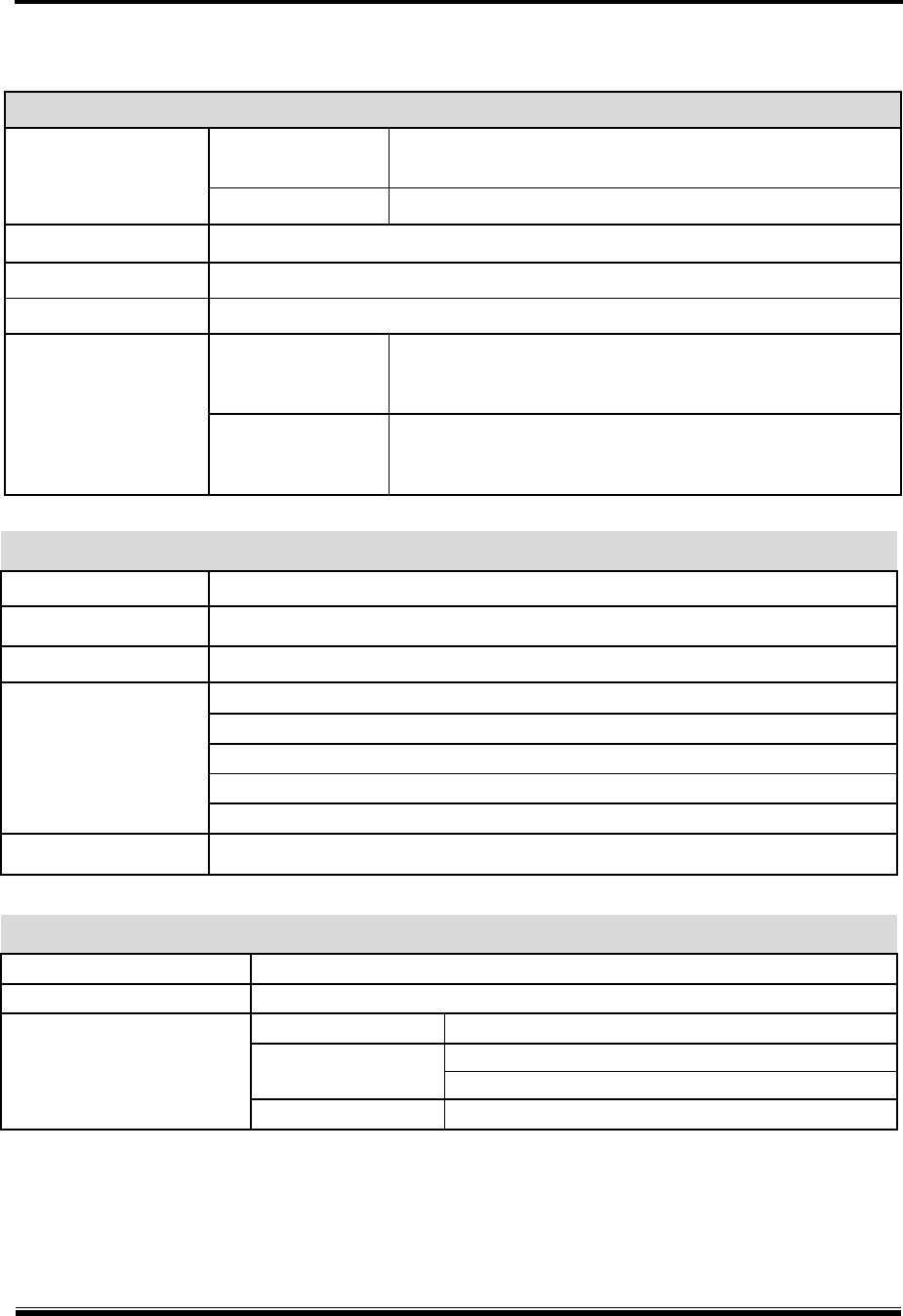
G1FZDHA001
Part Name: Carrying Hard Case
A portable and heavy duty
hard case that contains
G-scan2 base unit and parts.
1
G1CDDPA013
Part Name: AC/DC Adapter
AC to DC converter used for supply of
AC power to the G-scan2 base unit.
1
G1CDECA001
(Europe, Korea)
G0PDDCN001
(Australia)
G0PDDCN002
(UK, Malaysia)
G1PDDCA002
(North America)
Part Name: AC Power Cord
AC power cord used with the AC/DC
adapter for supply of AC power to
G-scan2 base unit
Different type AC plugs may apply for
different countries i.e. Korea, USA.
Australia and UK.
Spec: IEC 60320 C13
1
G2SDDCA003
Part Name: Cable – Battery
A power supply cable used together
with the Cigarette Lighter Cable when
supplying power from the car’s battery.
1
G1PDDCA002
Part Name: Cable-Cigarette Lighter
A power supply cable used when
supplying power from the car’s
cigarette lighter socket.
1
G1FZTZM001
Quick Manual
A single piece laminated paper manual
for quick guidance for G-scan2 usage.
G-scan2 User Manual
16
Non-standard OBD Adapters Asian Vehicles
Parts included in the Asian and Full Kit (Not included in Standard Kit)
Part Part Number Description Q’t
y
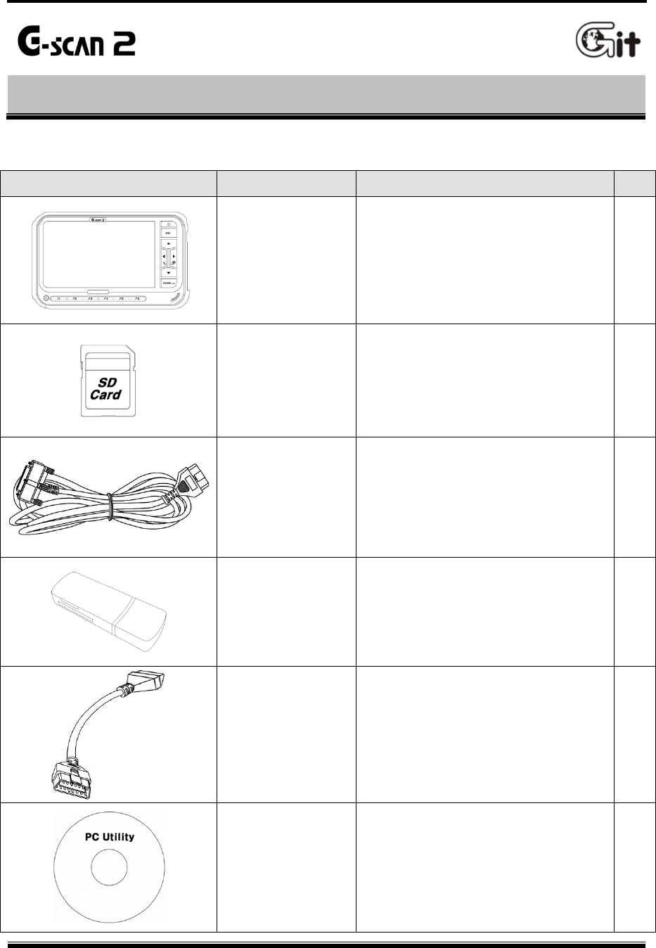
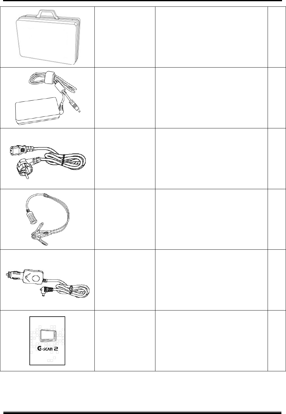
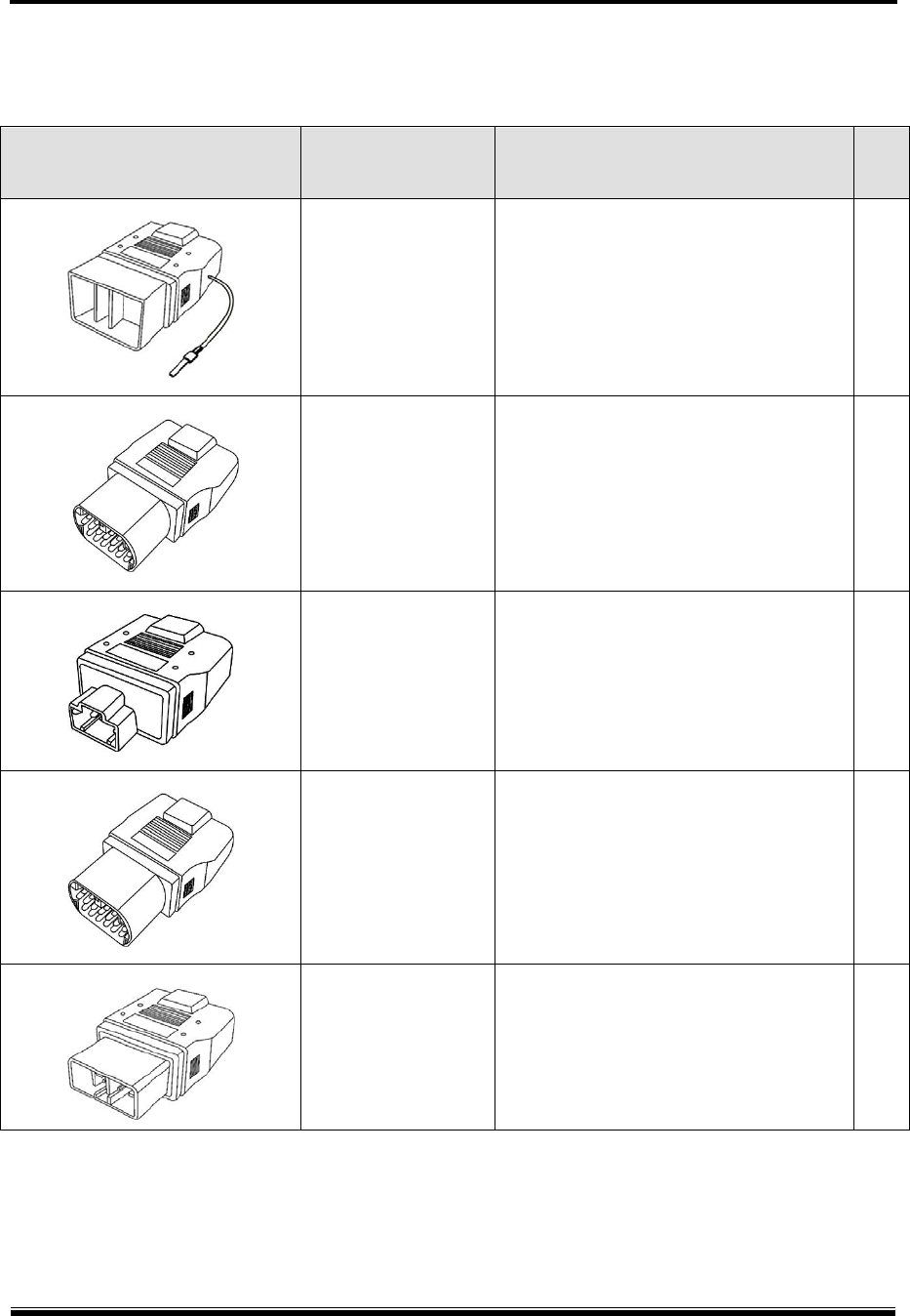
TOYOTA 17+1PIN Square
G1PZDPA001
Used for communication with old
Toyota and Lexus cars with 17+1 pin
“Square (rectangular)” type diagnostic
connector in the engine compartment.
1
TOYOTA 17P Round
G1PZFPA002
Used for communication with old
Toyota and Lexus cars with the 17-pin
“Round (Semi-circular)” type diagnostic
connector.
Same appearance as the Mazda 17P
adapter, make sure to check the name
engraved on the surface.
1
HONDA/ACCURA 3P
G1PZFPA003
Used for communication with old
Honda and Acura cars with the 3-pin or
5-pin diagnostic connector.
1
MAZDA 17P
G1PZFPA004
Used for communication with old
Mazda models.
Same appearance as the Toyota 17P R
adapter, make sure to check the name
engraved on the surface.
1
SUBARU 9P
G1PZFPA005
Used for communication with old
Subaru cars with the
9-pin diagnostic connector.
(Can be excluded from the Asian kit due to
regional preferences)
1
G-scan2 User Manual
17
MITSUBISHI 12P+16P
G1PZDPA002
Used for communication with old
Mitsubishi or Hyundai cars with the
12-pin single or 12+16pin dual
diagnostic connector.
1
Kia 20P-A type Connector
G1FDDPA001
Used for communication with old Kia
cars with 20 pin diagnostic connector
in the engine compartment.
Generally used for ‘99 ~ ‘02 MY cars.
1
Kia 20P-B type Connector
G1FDDPA002
Used for communication with old Kia
cars with 20 pin diagnostic connector
in the engine compartment.
Generally used for ‘03 ~ ‘05 MY cars.
1
Hyundai & Kia Keyless
Connector
G1CDDPA007
Used for some old Hyundai and Kia
models that require special connector
for keyless entry remote control coding
1
NISSAN 14P
G1PZFPA007
Used for communication with old
Nissan or Infiniti cars with
the 14-pin diagnostic connector.
1
Ssangyong 14P Connector
G2WDDCN006
Used for communication with old
Ssangyong cars with 14 pin circular
diagnostic connector in the engine
compartment
(Can be excluded from the Asian kit due to
regional preferences)
1
G-scan2 User Manual
18
Ssangyong 20P Connector
G2WDDCN007
Used for communication with old
Ssangyong cars with 20 pin square
diagnostic connector in the engine
compartment
(Can be excluded from the Asian kit due to
regional preferences)
1
Daewoo 12P Connector
G2WDDCN008
Used for communication with old
Daewoo cars with 12 pin diagnostic
connector
(Can be excluded from the Asian kit due to
regional preferences)
1
G-scan2 User Manual
19
Optional European Car OBD Adapters
Parts included in the Full Kit (Not included in Standard and Asian Kit)
BMW 20P
G1PZEPA001
Used for communication with old BMW
cars with the 20-pin circular diagnostic
connector.
1
AUDI / VW 4P
G1PZEPA002
Used for communication with old
Volkswagen, Audi, Seat or Skoda cars
with the 2 X 2 pin diagnostic connector.
1
BENZ 38P
G1PZEPA012
Used for communication with old
Mercedes Benz cars with the 38-pin
circular diagnostic connector in the
engine compartment.
(Can be excluded from the full kit and replaced
with the other optional adapters due to regional
preferences)
1
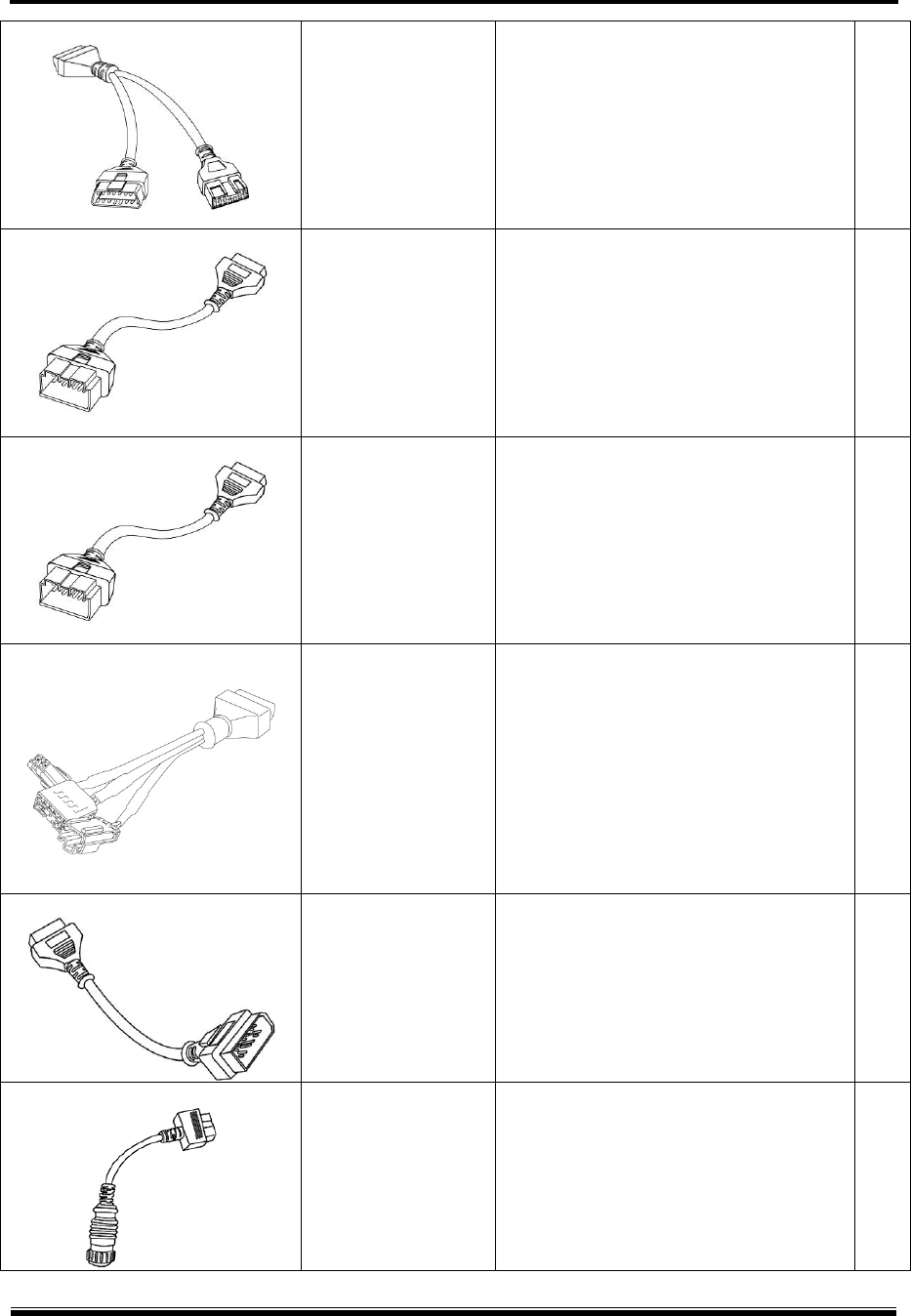
Optional Diagnostic Adapters for Commercial Vehicles and Rare Models
Parts available as optional supply
J1939 9-P adapter
G1PZDPA005
Used for generic communication with
SAE J1939 compatible commercial
vehicles
1
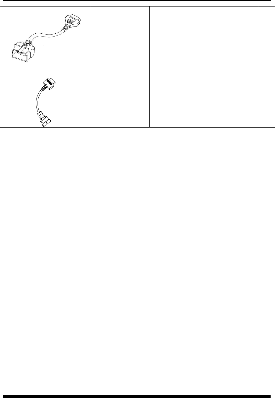
Isuzu 20-10-3P adapter
G1PZDPA006 Used for communication with old type
Isuzu commercial vehicles 1
G-scan2 User Manual
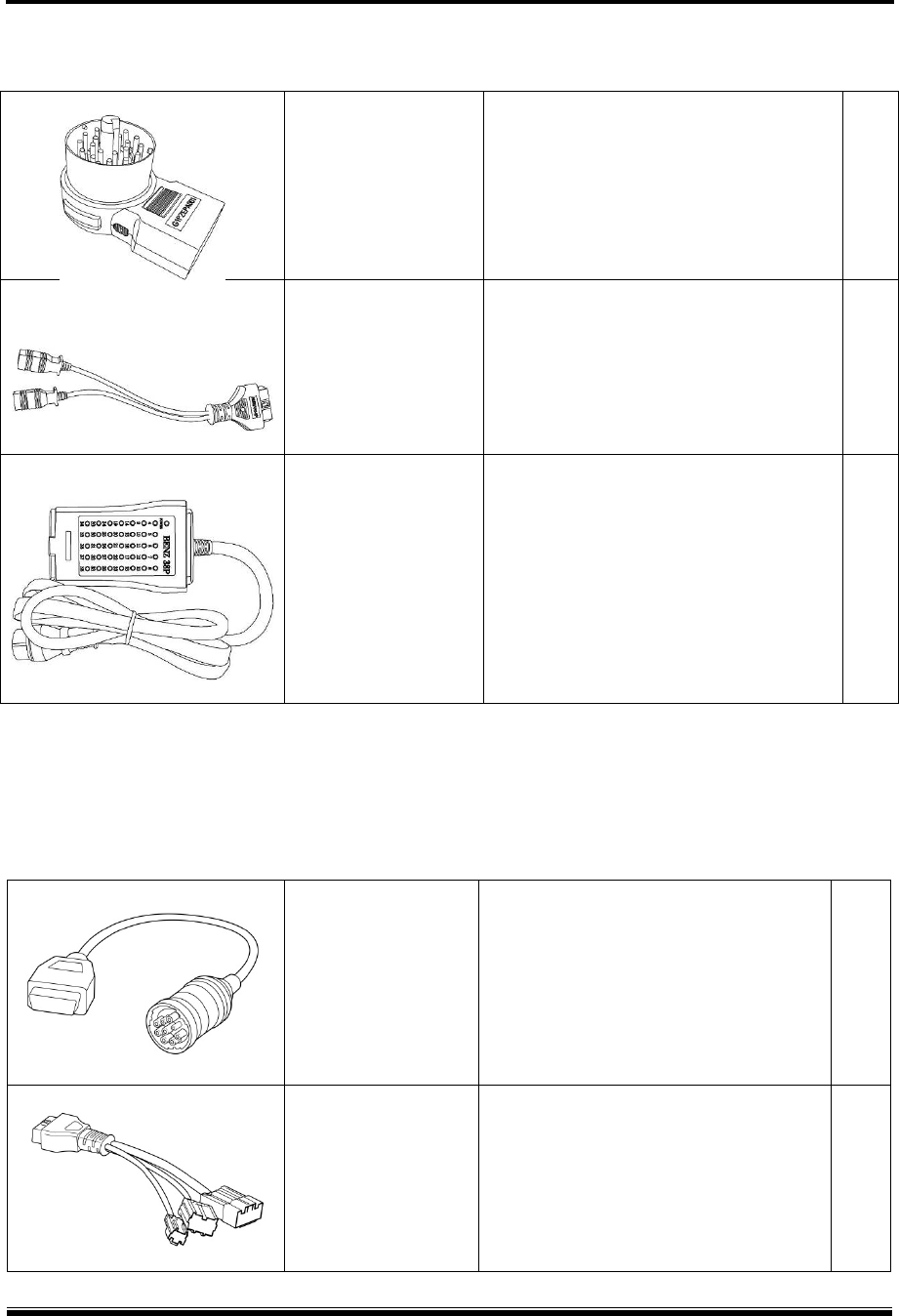
20
Universal Adapter
G2WDDCN010
Used for communication with the
vehicles that are fitted with non-
standard OBD adapters that G-scan’s
standard kit adapters are not
compatible
1
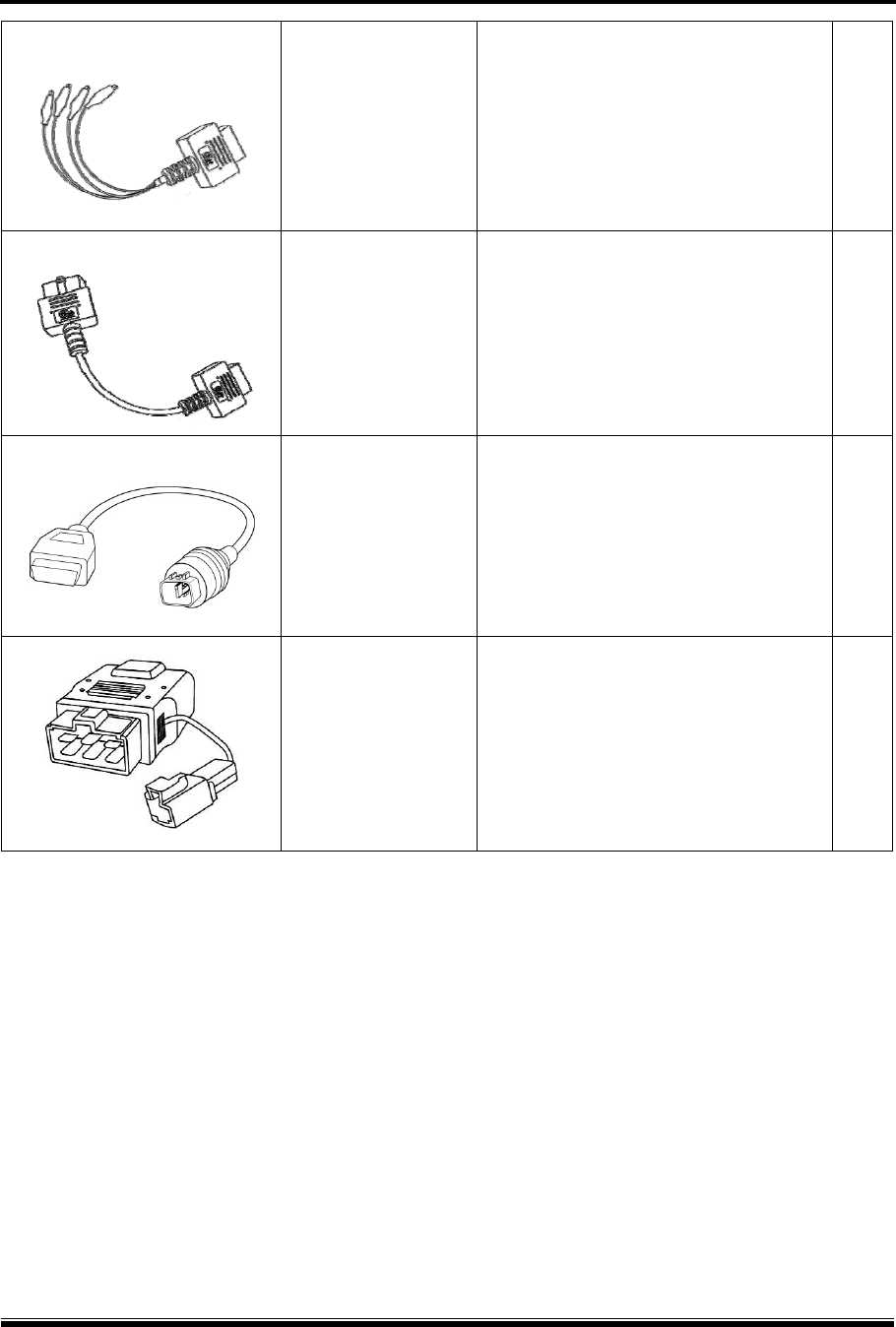
Hyundai Commercial 16-pin
G2SDDCA029
Used for most Hyundai and Kia
commercial vehicles.
Similar to standard OBD2 connector,
but the internal wirings are different.
Colored light grey for recognition
1
Hyundai Commercial 4-P
CNG
G1GDDPA001
4-pin circular connector used
specifically for Hyundai CNG
(Compressed Natural Gas) buses
1
Kia 6P Connector
G1CDDPA005
Used for communication with old Kia
cars with 6 pin diagnostic connector in
the engine compartment.
(Can be excluded from the Asian kit due to
regional preferences)
1
G-scan2 User Manual
21
Basic components for Measurement Functions
Parts supplied with the G-scan2 for measurement functions
G1FDDMN006
VMI Pack
Detachable rear module that enables
G-scan2’s oscilloscope, meter and
simulation functions. Part of G-
scan2 base unit, not sold separately.
Includes rechargeable battery.
1
G1FDDCA002
Ground Cable
Used for independent grounding of
the VMI circuit for stable and accurate
measurement
1
G1MTKCA002
Channel A Probe (Red)
Connected to the red Channel A port
of the VMI, used for acquiring electric
signal from the wires or terminals.
1
G1MTKCA003
Channel B Probe (Yellow)
Connected to the yellow Channel B
port of the VMI, used for acquiring
electric signal from the wires or
terminals
1
G1SDDCN005 Scope Pins (Red) 2
G1SDDCN005
(Part number
shared)
Scope Pins (Black) 2
G-scan2 User Manual
22
G1SDDCN005
(Part number
shared)
Spring Pin 2
G1SDDCN005
(Part number
shared)
Scope Clip (Red) 2
G1SDDCN005
(Part number
shared)
Scope Clip (Black) 2
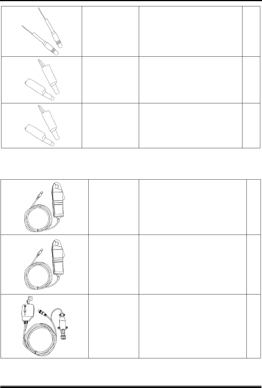
Optional components for Measurement Functions
Parts available as optional supplies
G1GDKCA003
Current Clamp, small current
Used for measurement of small current
of up to 20A
G1GDKCA004
Current Clamp, large current
Used for measurement of large current
of up to 100A or 1000A (switchable)
G1GDKCA006
Pressure Sensor
Used for measurement of pressure
G-scan2 User Manual
23
2.3. Details of the base unit
Getting Started with G-scan2 AA-2-3. Details of the base unit
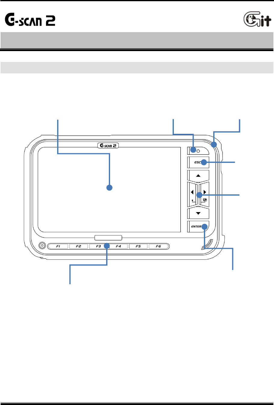
Touch Screen and Input Buttons
[ G-scan2 base unit front view]
LCD Touch Screen Power Key LED Indicator
ESC Key
4-way
Directional
Keys
ENTER Key
Function Keys
G-scan2 User Manual
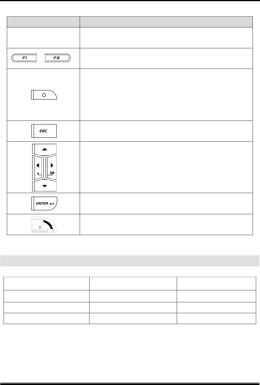
24
Part Name Function
Touch Screen Menu items, graphic buttons or icons are selected by directly
touching the screen
~
Different functions are assigned to the buttons, and the selected
function runs when pressed
Turns G-scan2 power On /Off
1) ON: Keep pressing the button for 0.5 seconds or more
2) OFF: Hold down the button for 1 ~ 2 seconds
3) A short press of the button, for less than 0.5 seconds while
G-scan2 is turned on, puts G-scan2 into the “Standby Mode”
Returns to the previous step or aborts the currently running
function
Moves the cursor up, down, left or right to select the item or
function in the menu
Pressing the Left and Right keys at the same time works as the
hot key for the screen capture.
Confirms the selection or executes the selected function
Indicates the power charging status of G-scan2.
RED: Charging, Green: Fully Charged, Blue: Stand-by Mode
LED Indicator Signal
Power Source When charging When fully charged
AC/DC adapter Red LED ON Green LED ON
DLC cable Red LED ON Green LED ON
Internal Battery Red LED ON Green LED ON
G-scan2 User Manual
25
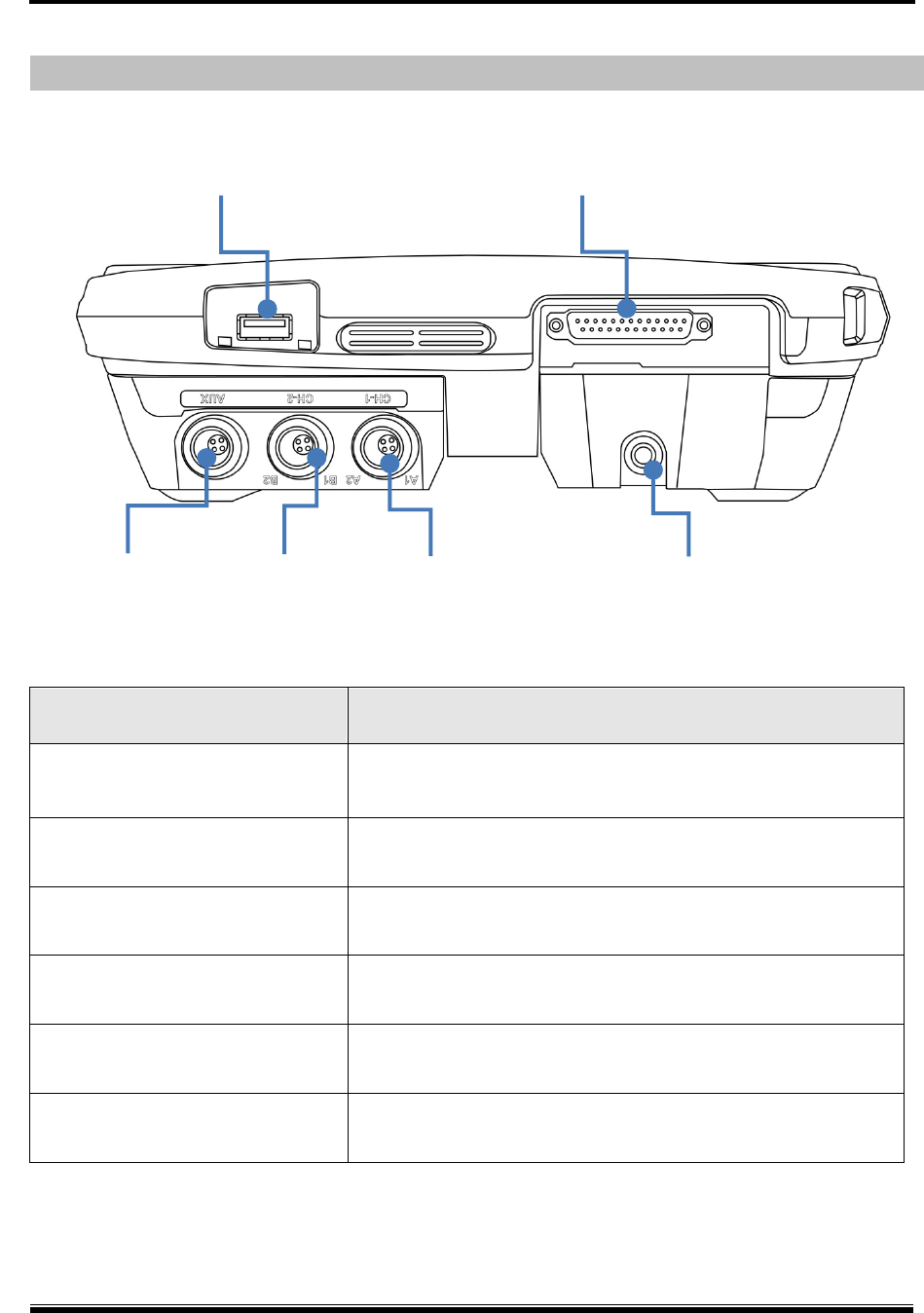
G-scan2 Hardware Configuration – Top
[ G-scan2 base unit top view ]
Part Name Description
DLC D-sub Main Data Link Cable is connected
USB port Standard USB cable is connected
Ground port (Green) Ground cable is connected for the measurement functions
Channel A (CH-A) port (Red) CH-A oscilloscope probe cable is connected for the
measurement functions
Channel B (CH-B) port (Yellow) CH-B oscilloscope probe cable or the pressure sensor is
connected for the measurement functions
AUX port (Blue) Current sensor, Small or large, is connected for the
measurement functions
USB Port Main Data Link Cable D-Sub
Channel B port Channel A port Ground port
AUX port
G-scan2 User Manual
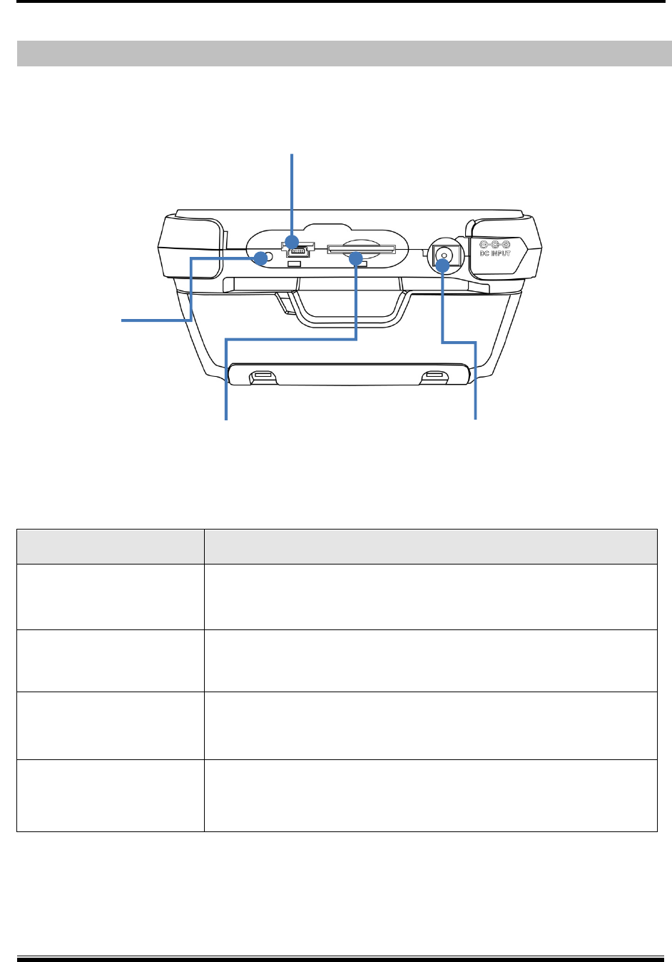
26
G-scan2 Hardware Configuration – Side
[ G-scan2 base unit side view ]
Part name Description
Reset button Resets G-scan2 by force in case the system is unable to shut down
normally due to the software failure caused by O/S defect or others
Mini USB port Mini-USB cable is connected
SD Card memory slot Accommodates the SD Card
DC input jack AC/DC Adapter or Cigarette Lighter Cable is connected for the
supply of external power to G-scan2
Mini USB port
Reset button
DC Input jack
SD Card memory slot
G-scan2 User Manual
27
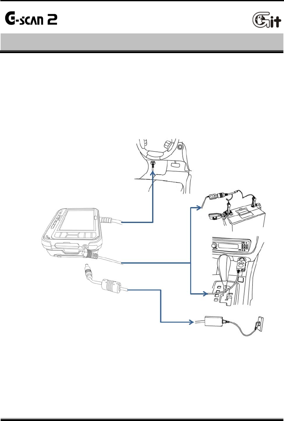
2.4. Power Supply to G-scan2
Getting Started with G-scan2 AA-2-4. Power Supply to G-scan2
Power supply to G-scan2 is available from 4 different sources.
from diagnostic connector
from cigarette lighter socket
from vehicle battery
from AC outlet (through AC/DC adapter)
[ Delivery of power to G-scan2 ]

G-scan2 User Manual
28
from the diagnostic adapter
1. Extend the G-scan2 main cable to the vehicle side diagnostic socket. Attach the paring OBD
non-standard connector if necessary.
2. Turn the ignition key to ACC or ON position, and power is supplied to G-scan2.
The power is supplied through the diagnostic socket even when the IG key is turned OFF.
However, please note that the IG key must be turned ON for diagnostic communication.
3. By the industrial standard, all OBD-2 / EOMB compliant vehicles are designed to supply power
through the diagnostic adapter.
4. The vehicle side DLC socket is recommended to be placed within 1 meter from the driver’s
seat. It is generally found under the dashboard. However, be reminded that there are
exceptions.
from the cigarette lighter socket
1. Connect the cigarette lighter power cable to G-scan2’s DC input jack.
2. Extend the cable and insert the connector to the vehicle side cigarette lighter socket
3. Turn the ignition key to ACC or ON position, and power is supplied to G-scan.
In case of drawing power from the cigarette lighter socket, the power is lost when cranking
the engine causing G-scan2 to turn off if the internal battery is discharged or not installed.
It is recommended to use the other power source if rechargeable battery is not charged or
the battery pack is not installed to G-scan2
from the vehicle battery
1. Connect the cigarette lighter power cable to G-scan2’s DC input jack.
2. Attach the battery cable with the alligator clips to the end of the cigarette lighter power cable.
3. Beware of the battery polarity, and extend the red clip to the (+) terminal of the vehicle
battery and the black one to the (-) terminal.
4. Turn the ignition key to ACC or ON position, and power is supplied to G-scan2.
Caution
Never connect the battery cable clips to the reversed polarity terminals.
It may cause serious damage to G-scan2.
G-scan2 User Manual
29
from AC outlet
1. Connect the DC jack of the AC/DC converter to G-scan2’s DC input jack.
2. Extend the AC plug of the AC/DC converter to the AC outlet.
3. Power is supplied to G-scan2
Caution
Make sure to use the AC/DC adapter that is supplied with G-scan2.
Damage caused from use of unapproved AC/DC adapter is not subject to warranty service.
Turning G-scan2 ON
Hold down the POWER button for about 0.5 seconds to turn the G-scan2 on.
The LED indicator illuminates in blue which goes off shortly after, then the G-scan2 booting
sequence is initiated. The booting sequence is followed by the main menu display.
Turning G-scan2 OFF
Hold down the POWER button for about 2 seconds to turn the G-scan2 off.
“The system is shutting down” message appears on the screen, the LED indicator shortly
illuminates in blue, then the G-scan2 is powered off completely.
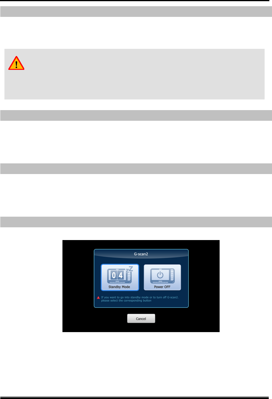
Switching G-scan2 to Standby mode
A stand-by mode query pops up when the POWER button is pressed shortly as shown below:
Wait until the timer counts down to zero, then the G-scan2 switches to “Standby mode”. In
Standby mode, G-scan2 hibernates until any key is pressed. Upon any key stroke or a screen
touch, it resumes normal operation instantly without going through the boot-up sequence.
Select “Power OFF” to turn the G-scan2 off completely.
In case of unintended stroke of POWER button or pressed by accident, select “Cancel”.
G-scan2 User Manual
30
2.5. Rechargeable Battery
Getting Started with G-scan2 AA-2-5. Rechargeable Battery
G-scan2 is fitted with the Li-Ion rechargeable battery pack as the basic supply, and it enables the
device to run normally when the external power supply is lost. However, drawing power from the
car is always recommended for diagnostic communication stability.
1. Connect DC jack of the AC/DC adapter to G-scan2’s DC input jack.
2. Extend the adapter plug of the AC/DC adapter to the AC outlet.
3. LED indicator illuminates in red when charging the battery. When fully charged, the LED
turns to green.
Charging Fully Charged
Red LED On Green LED On
Warning
Frequently check the battery indicator icon on the corner of the screen when operating
G-scan2 on its battery without an external power source.
Recharge the battery immediately by supplying external power when the battery status
appears low; otherwise G-scan2 will turn off automatically.
G-scan2 User Manual
31
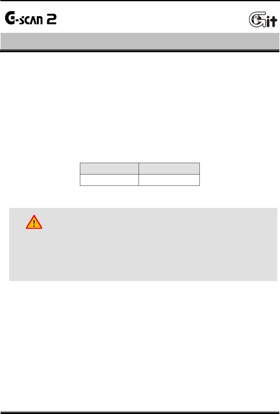
Rechargeable Battery Replacement
A rechargeable battery is an expendable supply of which performance deteriorates over the
repeated recharging cycles, and the replacement of the battery is recommended when the
lowered charging performance is experienced.
Open the rear battery cover and lift the battery to remove.
Insert the new battery in place and close the cover.
[ Rechargeable Battery Replacement ]
G-scan2 User Manual
32
2.6. Connecting to the vehicle
Getting Started with G-scan2 AA-2-6. Connecting to the vehicle
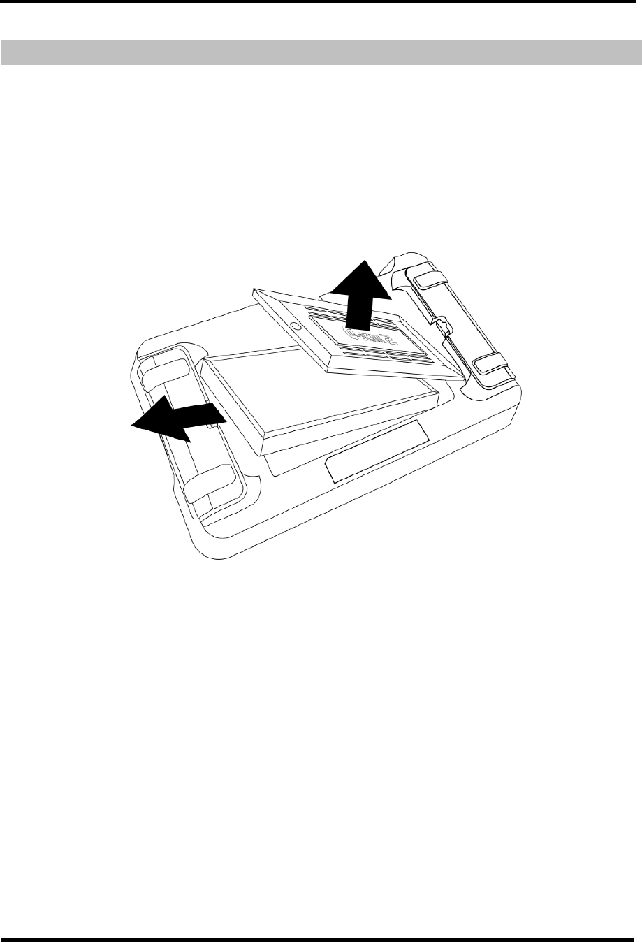
Connecting the main DLC cable to the base unit
Connect the DLC main cable to the G-scan2 D-sub connector, and secure the connection by
fastening the 2 main screws as well as the 2 vertical screws. Do not apply excessive power
when fastening the screws.
Connecting to the Vehicle
Extend the DLC main cable connected to the G-scan2 to the vehicle side DLC socket.
Different types of diagnostic adapter may be used for the old models or the commercial vehicles.
If the vehicle is not OBD2 / EOBD compliant, identify and attach the matching adapter, then
connect it to the vehicle side socket.
Warning
Do not hold the G-scan2 base unit by the main cable when carrying the
product. Make sure to hold the base unit or the hand strap
G-scan2 User Manual
33
2.7. Rear Pack Replacement
Getting Started with G-scan2 AA-2-7. Rear Pack Replacement
G-scan2 rear pack replacement
G-scan2 is supplied with the VMI rear pack which offers the measurement capability including
oscilloscope, digital multi-meter and simulation functions.
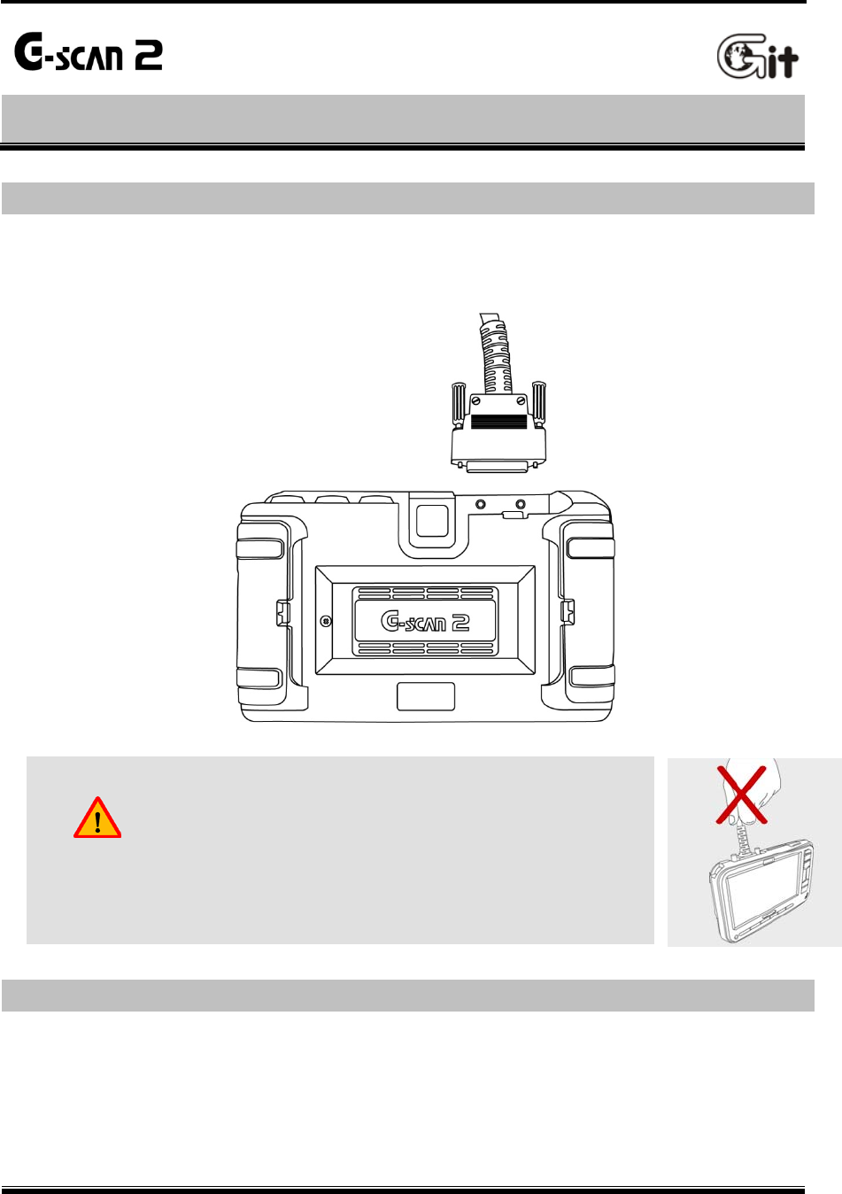
1. Detaching
Unlock the lockers on both sides by pressing them sideways
Swing open the locker hinges, then the rear pack is released
Detach the rear pack from the base unit by lifting gently
[ Rear pack removal ]
Locker
G-scan2 User Manual
34
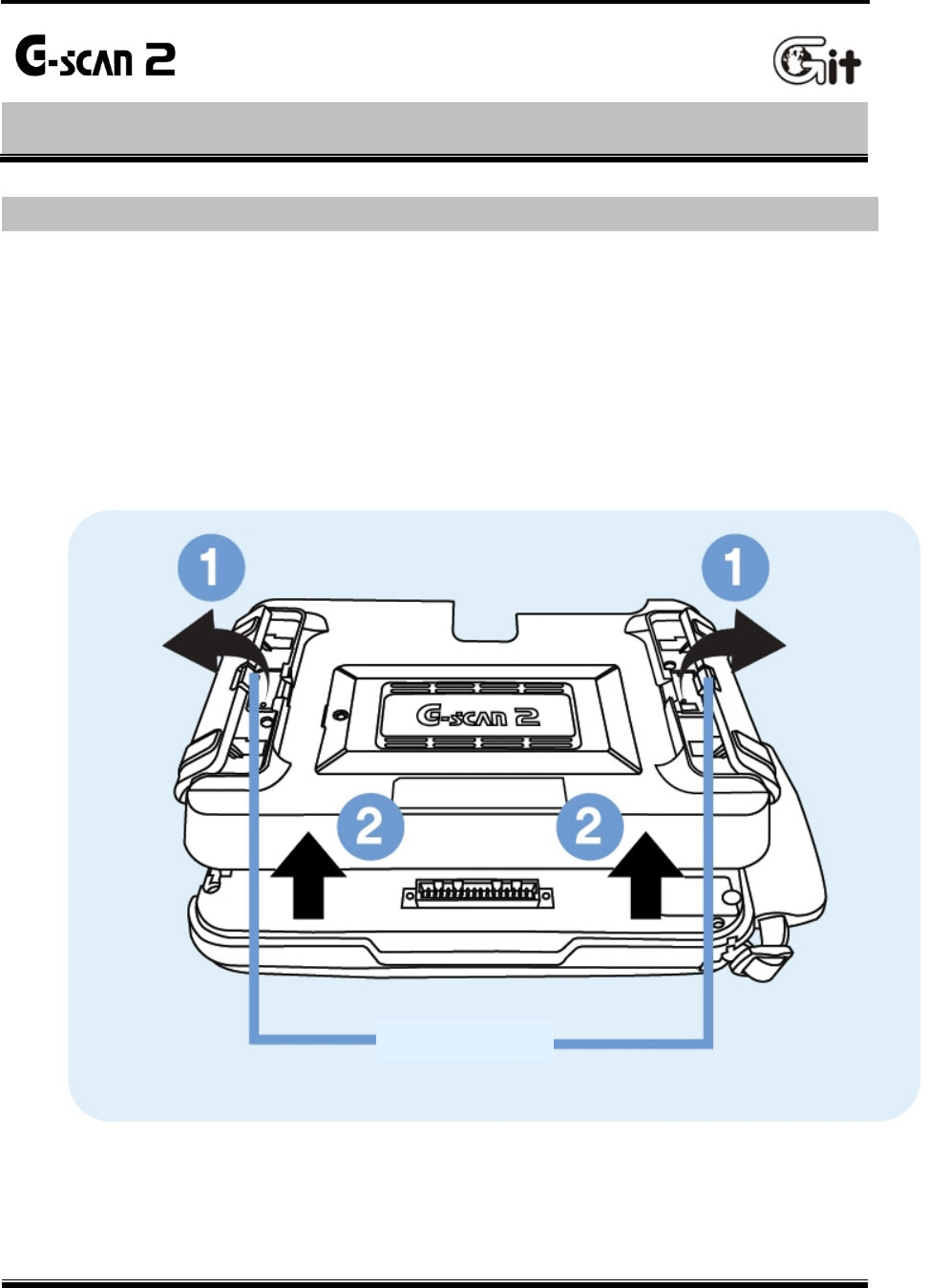
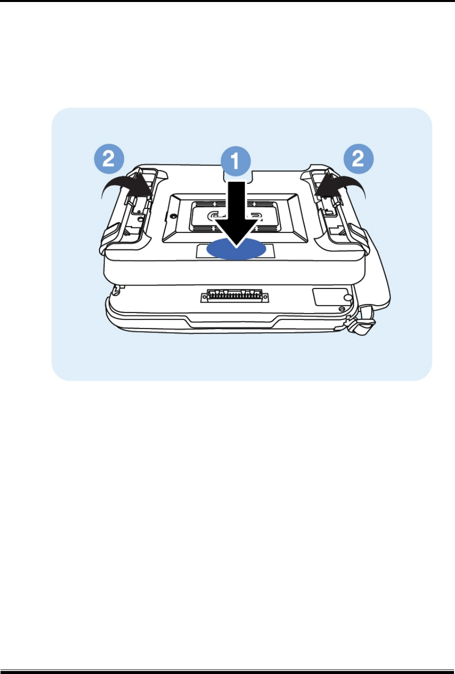
2. Mounting
Put the rear pack well aligned in place
Lock the rear pack to the base unit by gently pressing down the center part
Swing close the locking hinges on both sides.
[ Rear pack mounting ]

G-scan2 User Manual
35
3.1. Main Menu and System Tools
3.2. Recorded Data
3.3. OBD-II
3.4. Vehicle Diagnosis
3.5. Measurement
3.6. Favorite
3.7. G-scan2 System Lock
Chapter 3 G-scan2 Basic Operations
G-scan2 User Manual
36
3.1. Main Menu and System Tools
G-scan2 Basic Operations AA-3-1. Main Menu and System Tools
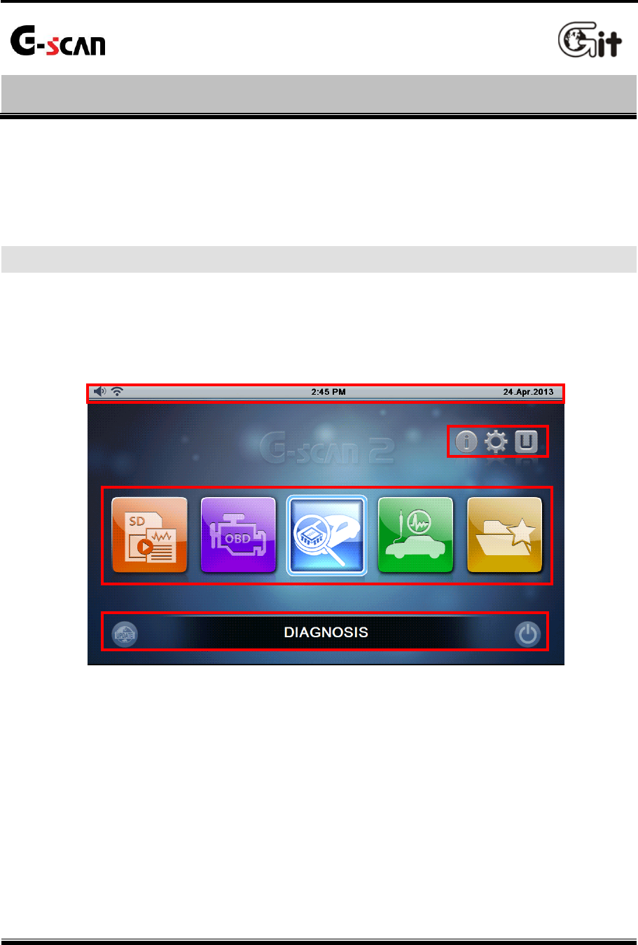
The main menu as shown below appears when G-scan 2 is turned on.
Please refer to the information about the main menu items and functions provided in this chapter
for further usage of G-scan2 product.
The main menu of G-scan2 is consisted of 4 sections (header, additional functions, major
functions and bottom).
[4 sections of main menu]
Main menu
G-scan2 User Manual
37
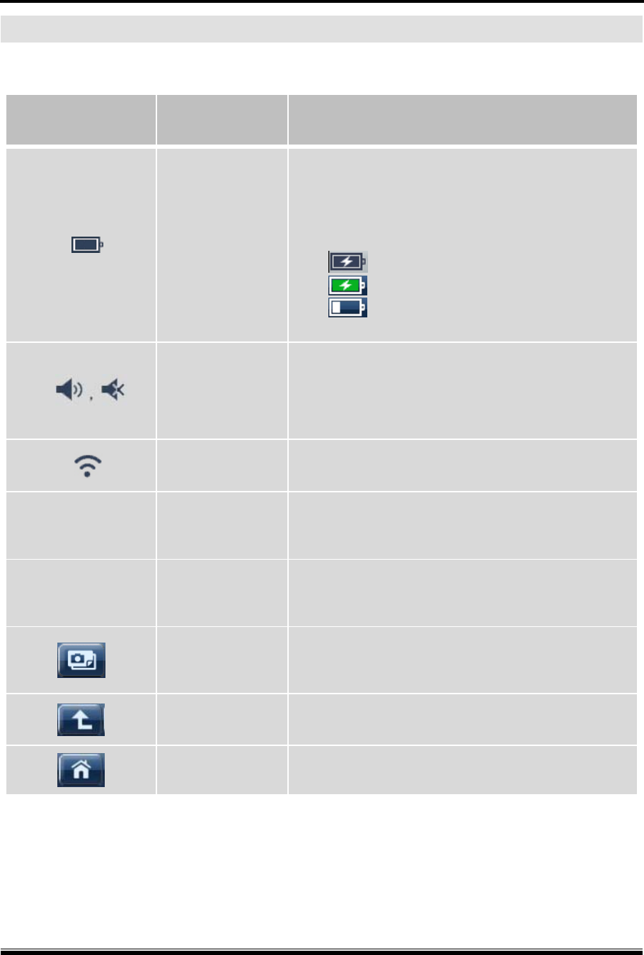
The header carries different type of information and indicators according to the selected functions.
Icon Name Description
Battery Status
Indicates the battery charging status
* A rechargeable battery is an expendable supply
of which performance deteriorates over
repeated recharging cycles.
: Charging
: Fully charged,
: Battery balance
(while running on the battery power).
Volume
Level of speaker volume (loudness).
Switching off the speaker is possible from the
configuration menu.
WiFi Status Indicates the WiFi (WLAN) connection status
12:00 AM time Indicates the system time
13 Jul 2013 Date Indicates the system date
Screen
Capture
Captures the current screen and saves to the SD
card memory.
Previous Moves back to the previous step
Home Jumps to the Main Menu
Main menu - Header
G-scan2 User Manual
38
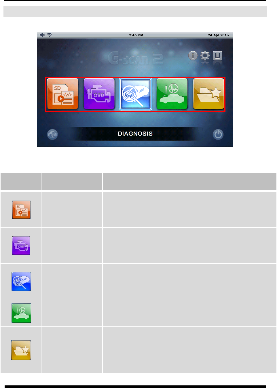
Main Functions
[ Main Functions ]
Icon Title Description
Recorded Data
Retrieves data files recorded in the SD card, including flight
record data, saved oscilloscope waveforms and screen
captures
OBD-II
Performs Generic OBD2/EOBD diagnostic functions for the
ISO9141-2, ISO14230 (KWP2000) and ISO15765-4 (CAN-
Bus) compliant vehicles.
Diagnosis
Runs manufacturer specific diagnostic functions including
DTC Analysis, Data Analysis, Actuation Test, ECU Info and
various Special Functions for each car manufacturer.
Measurement Executes the vehicle measurement features including
oscilloscope, digital multi-meter and simulation functions.
Favorite
Opens the favorite functions folder where the frequently
used functions are listed and organized by the user. The
listed functions can be revisited simply without having to
navigate the multiple menu layers each time.
G-scan2 User Manual
39
Additional Function Section
Includes the icons of the additional functions that can be directly selected from the main menu,
including Quick User Guide, Configuration, and Utility.
Icon Name Description
Quick User
Guide
Opens the Quick User Guide, where the simplified user’s
manual can be viewed. Refer to the user’s manual
included in the PC Utility program for more details.
Configuration
Opens the configuration menu where software version
information check, date and time set, language selection
and various user settings can be reviewed and changed.
Utility
Calls the various utility programs such as “Vehicle
Communication Line Check”, “Unit Converter”,
“Calculator”, “Special Function Calculator”, etc.
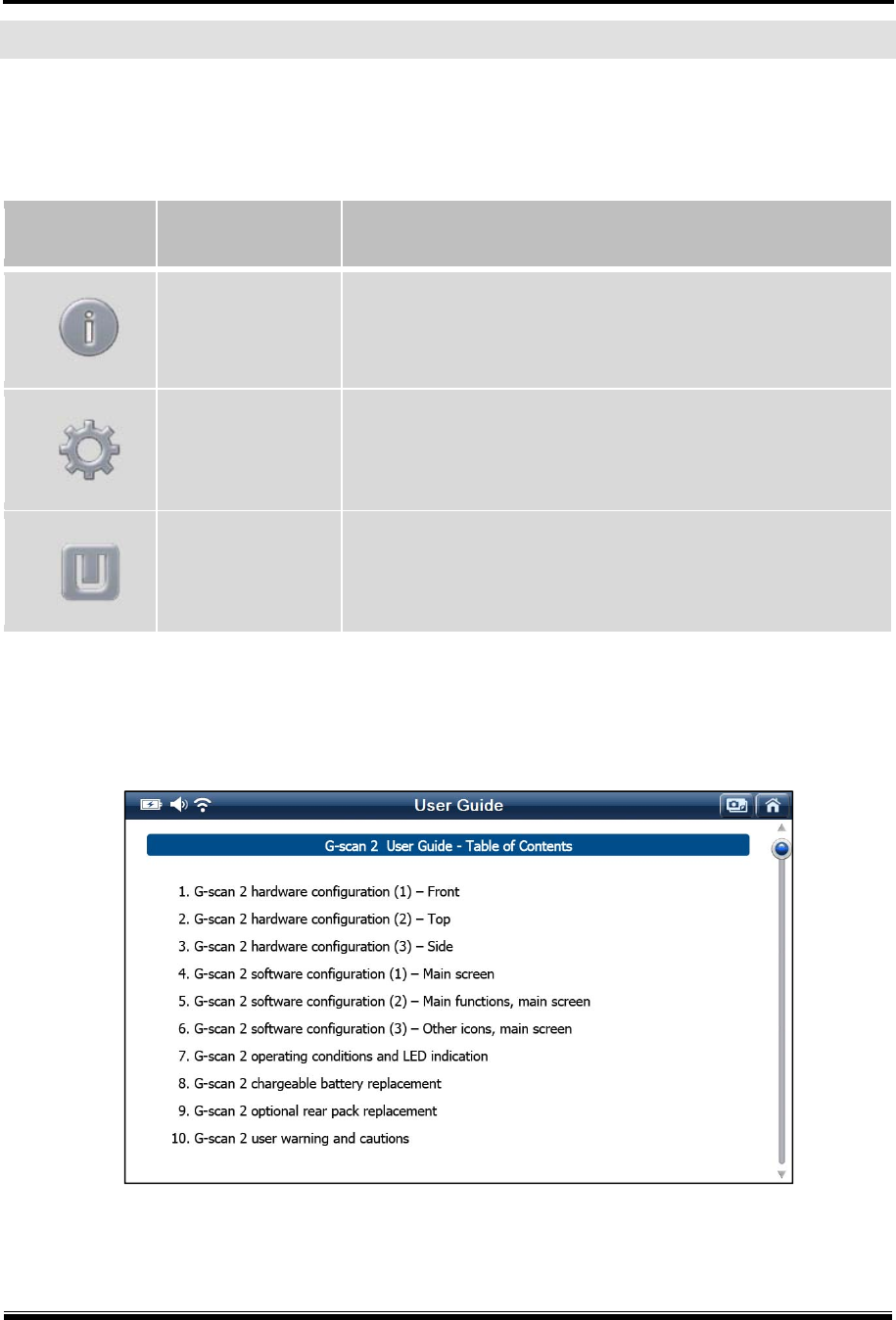
1. Quick User Guide
Select “Quick User Guide” from the G-scan 2 main menu among the Additional Functions icons
to view the simplified user’s manual for quick reference.
[ Quick User Guide – Index ]
G-scan2 User Manual
40
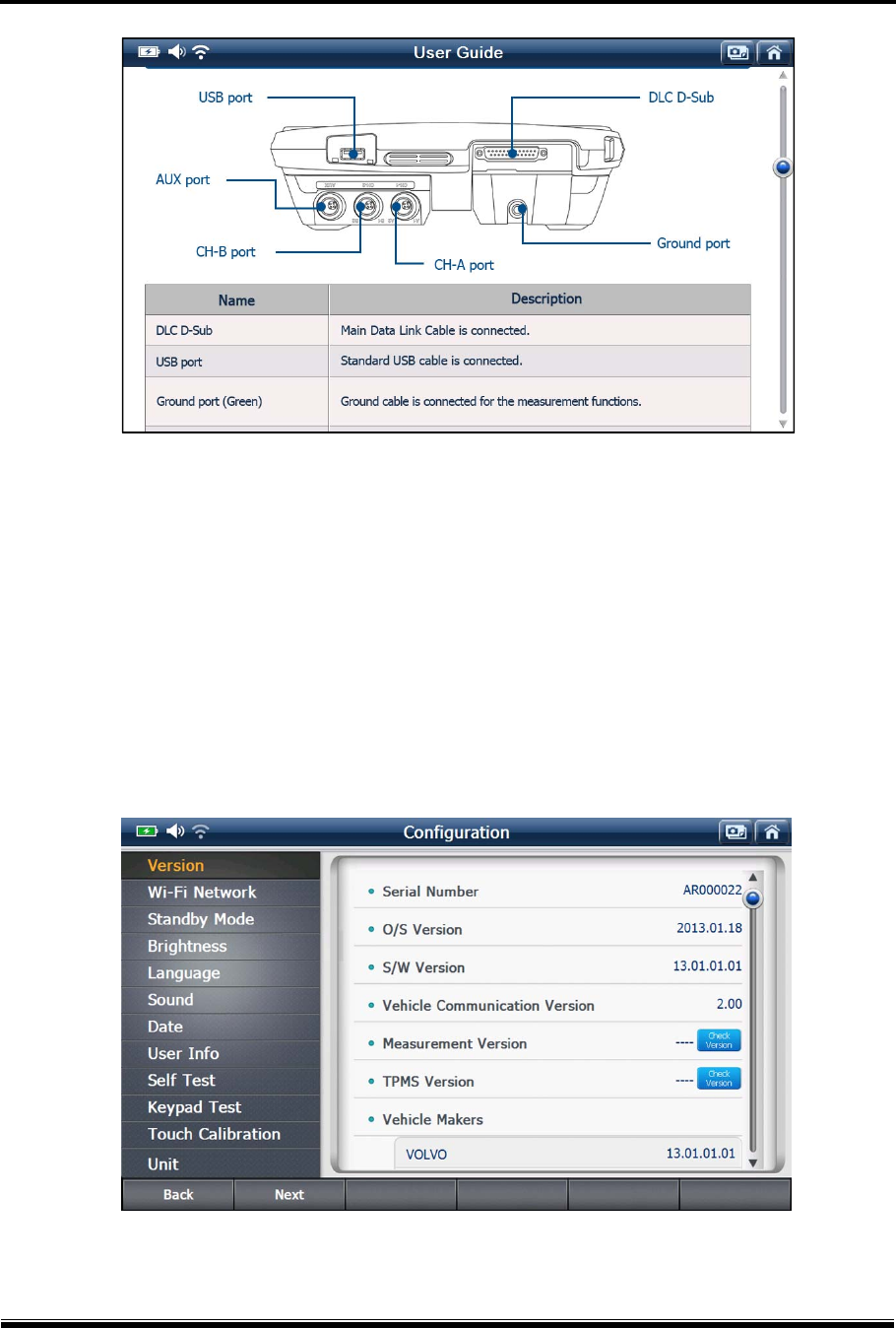
[ Quick User Guide – Main Body ]
2. Configuration
Select the “Configuration” among the Additional Functions icons to check the software versions,
set up the WiFi connection, perform the self-test, keypad test or touch screen calibration, or
change the various user settings such as stand-by mode, brightness, sound, user information.
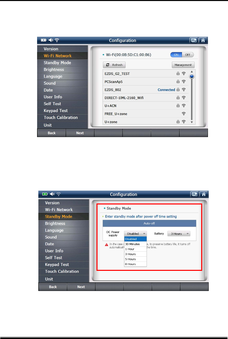
2-1. Software version
The G-scan2 serial number and the version numbers of operating system and the individual
diagnostic programs can be checked.
[ G-scan 2 Configuration – Software Version ]
G-scan2 User Manual
41
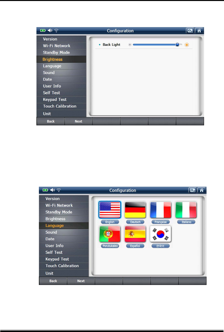
2-2. Wireless Network
Wireless network status can be checked. The Wireless network setup can be carried out from
the PC Utility’s Configuration menu.
[ G-scan 2 Configuration - Wireless Network Status ]
2-3. Stand-by mode setting
Automatic power off while G-scan2 is hibernating in stand-by mode can be selected from the
drop down menu either when powered by the DC Power input or the internal battery.
G-scan2 User Manual
42
2-4. LCD Brightness Control
Brightness of the LCD Backlight can be adjusted
2-5. Language
Select the preferred language among the supported languages (if available). The
languages are supported in different set by the regions. Generally English is the primary
language with the different local languages supported as the secondary.
G-scan2 User Manual
43
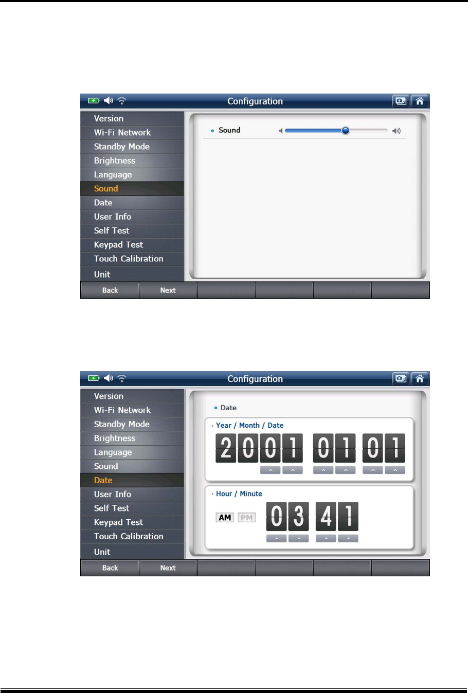
2-6. Sound
The loudness of the sound that G-scan2 internal speaker can be adjusted.
The speaker turns to mute when adjusted to the lowest level.
2-7. Date
The date and time that are applied while using G-scan2 can be set and adjusted.
G-scan2 User Manual
44
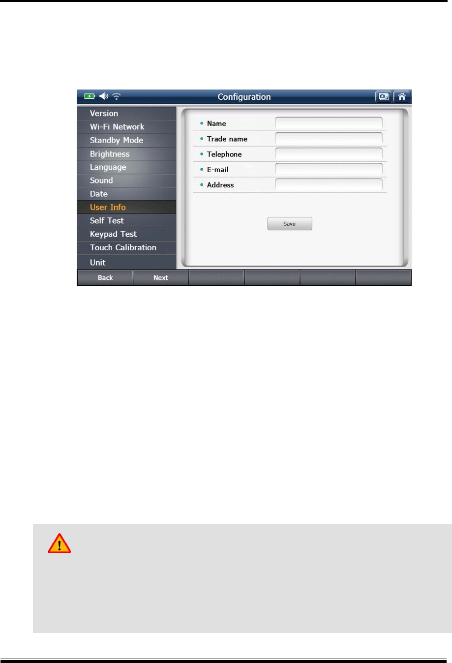
2-8. User Information
G-scan2 user information can be reviewed.
. The user information can be inputted or revised from the PC Utility’s Configuration menu.
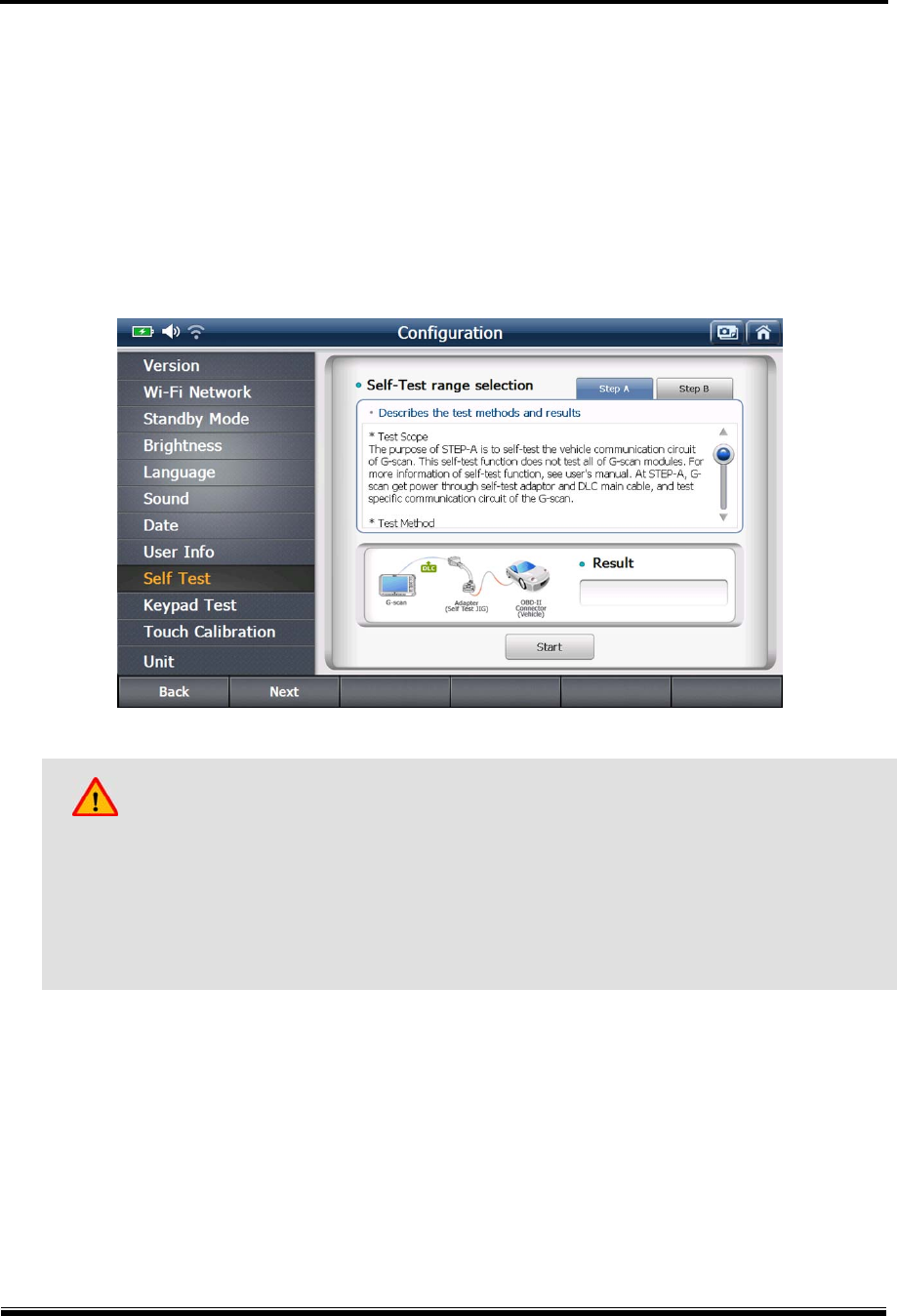
2-9. Self-test
In case the G-scan2 fails in performing the diagnostic functions properly, Self Test function
helps the user identify whether the communication problem is caused by the defective DLC
main cable or the malfunction of the base unit. (This function does not tell which part of G-
scan2 is defective)
Self-test is designed based on the Loop Back system, with which G-scan2 sends off signals
from the base unit through the DLC cable, and the self-test adapter returns the signal back to
the base unit. By sending signals from different channels and lines, and verifying the
correctness of every signal echoed from this looped connection in each case, it becomes
identifiable where the communication failure originated.
Caution
Loop back test is not supported in some vehicles with High Speed CAN, Low Speed
CAN and SAE J1708 communication systems.
Self-test can be used with OBD-II / EOBD compliant cars only. Cannot be used with
OBD1 generation cars with non-standard adapters.
G-scan2 User Manual
45
The Self-test is consisted of 2 steps: STEP-A and STEP-B.
Please observe and follow the instructions given on the screen during the test.
The Self-test Adapter is used for the both steps.
Step-A : Checks the internal communication control circuit of G-scan2 base unit
Step-B : Checks the signal delivery circuit of the DLC main cable
Caution
Please make sure to connect the Self-Test Adapter to the vehicle’s diagnostic connector
before starting the Self-Test process. The Self-adapter is a dedicated adapter used only for
the self-testing purpose. Never use the Self-Test adapter for normal vehicle diagnosis, or it
may cause serious damage to the vehicle and the G-scan2.
G-scan2 User Manual
46
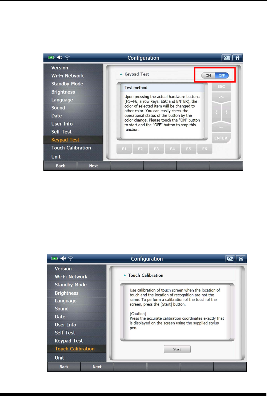
2-10. Keypad Test
Individual hard keys can be tested by observing the response of G-scan2 to a stroke.
Switch the ON/OFF selector on the screen to “ON” to initiate the Keypad Test and refer to the
Test Method for further process.
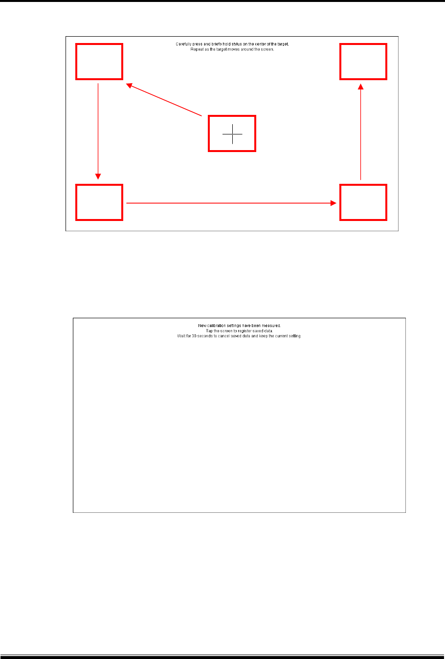
2-11. Touch Screen Calibration
G-scan2 may activate unwanted menu or item if the touch screen is not calibrated properly.
The touch screen needs recalibration if the coordination of the actual position of the touched
point is not recognized by the G-scan2 correctly.
A. Select “Touch Calibration” from the Configuration menu and select “Start”
G-scan2 User Manual
47
B. Touch the center of the crosshair one after another on the screen as shown below.
C. Touch any position on the screen to complete the process if you see the “Calibration
Completed” message as shown below. If you want to cancel the calibration, wait for 30
seconds until the timer counts down to zero.
G-scan2 User Manual
48
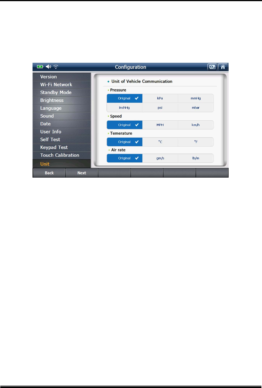
2-12. Unit
G-scan2 shows the parameter values and the measuring units just as the vehicle’s Electronic
Control Unit is programmed. However, it the different measuring units are preferred, the units
can be selected among the given variations as preferred.
[ Default measuring units as the vehicle’s ECU is programmed ]
G-scan2 User Manual
49
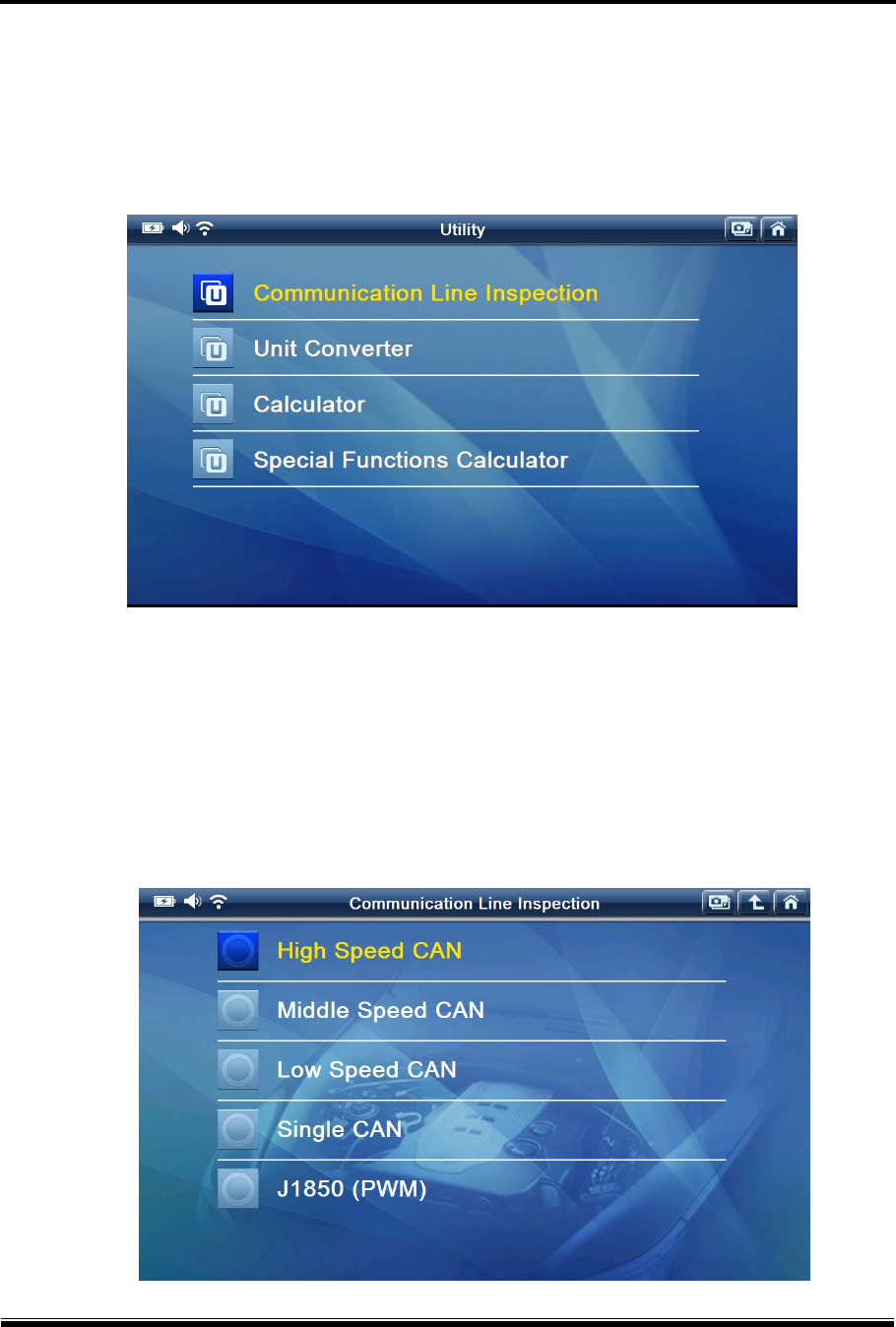
3. Utility
G-scan2 offers a variety of utility functions for user’s convenience.
[ Utility Functions ]
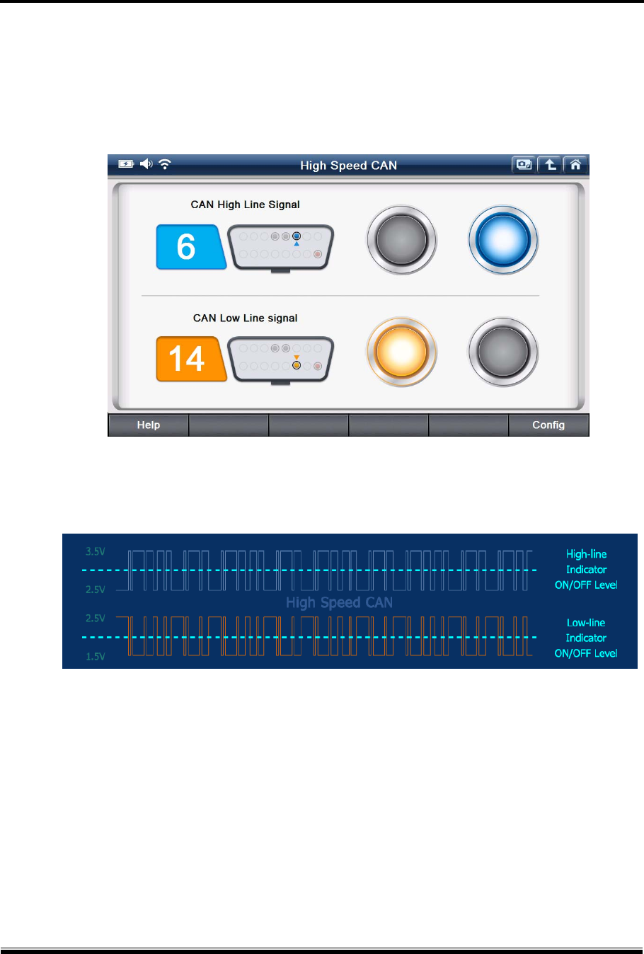
3-1. Communication Line Inspection
The electronic control systems fitted in the cars are designed to comply with the specific
communication protocols, and the electronic control units communicate with the G-scan2 based
on the protocol as they are designed through the diagnostic adapter, mostly through the OBD2
socket.
G-scan2 User Manual
50
This function helps the user figure out whether the vehicle’s electronic control units
communicate with the other control units properly or not by indicating the status of the
communication signal by illuminating ON-OFF lamps by sensing the change of the voltage level
of the communication signal pins of the diagnostic socket.
5 types of communication protocols including High Speed CAN-bus, Middle Speed CAN-bus,
Low Speed Can-bus, Single CAN-bus and SAE J1850 (PWM) are supported by this test
function.
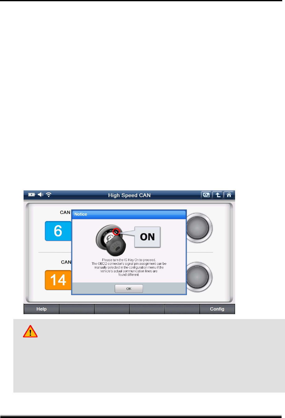
The same procedure is applied for all the protocols. Therefore refer to the following example
based on testing the High-speed CAN-Bus system, and consider the same procedure when
testing the other communication protocols.
A. Check the ‘Notice’ pop-up and select “OK” to continue.
As instructed, make sure to turn the IG key to ON position.
Caution
This function works based on the standard communication line assignment.
However, sometimes the communication lines may be assigned to the different pins of
OBD2/EBOD adapter for different cars according to the non-standard design by the car
manufacturers.
Please refer to the circuit diagram of the test vehicle and check the correct communication
lines if the function fails due to no signal input. If the communication lines are found assigned
G-scan2 User Manual
51
to the different pins, please select “Configuration” button in the bottom right, and change the
settings accordingly.
B. Select “OK”, then the OBD2 connector pin numbers that the signals are being transmitted
are indicated, and “Indicator lamps” illuminate in turn.
The illuminating “Indicator lamp” indicates that the change of voltage is being sensed from
the communication lines as illustrated below.
If the lamps are not flashing, check the IG Key ON status and the OBD2 connector’s signal
pin assignment, then make closer inspection on the circuit.
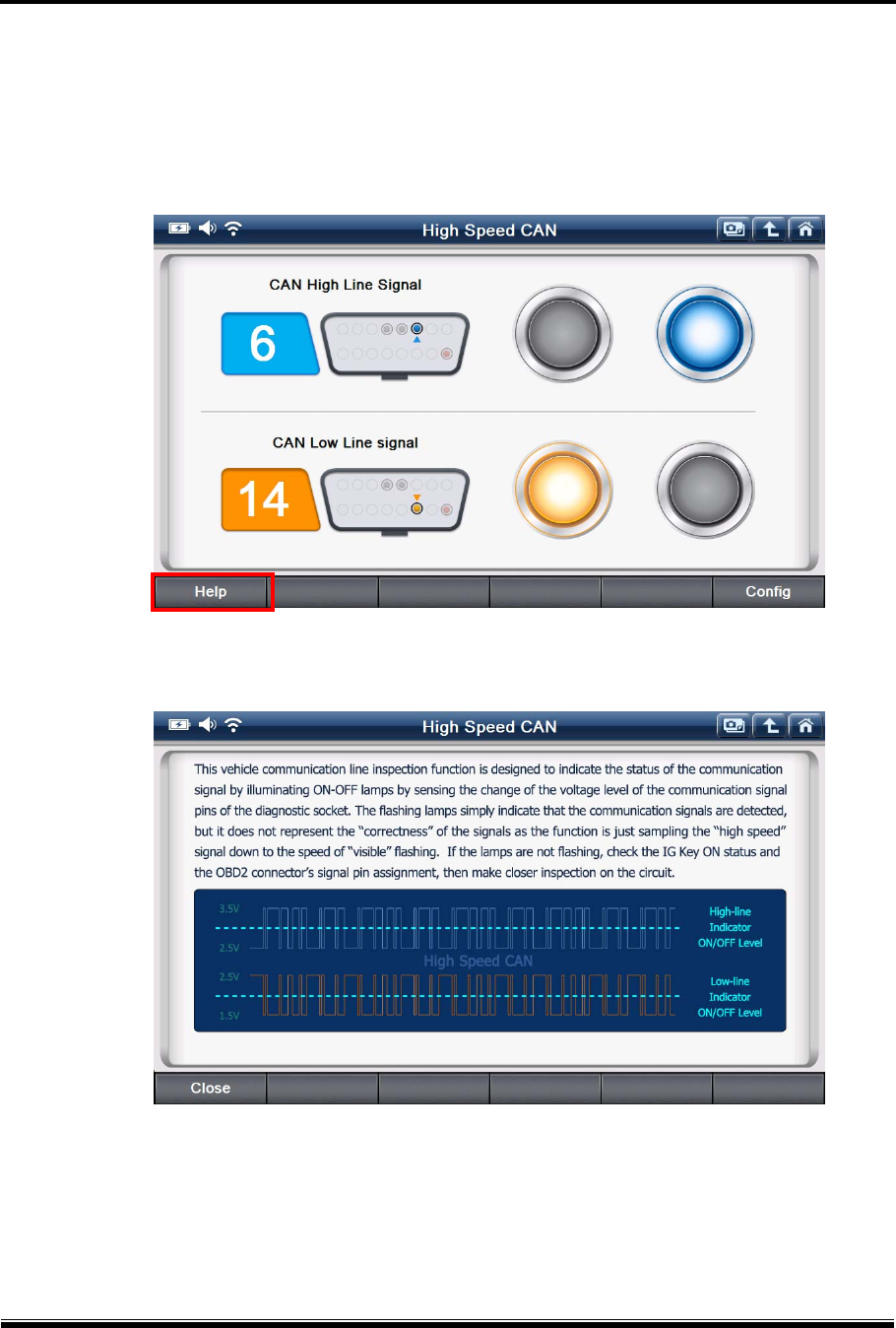
This function offers ability to test the communication of the vehicle’s control system indirectly.
Please mind that the result of this function may differ from the direct reading from the
communication lines, because the function is not measuring the voltage from the
communication lines, but indirectly senses the voltage fluctuations through the OBD2 socket.
G-scan2 User Manual
52
Also, the flashing lamps simply indicate that the communication signals are detected, and it
does not represent the “correctness” of the signals as the function is just sampling the “high
speed” signal down to the speed of “visible” flashing.
Select “Tips” and the additional information about the function follows as shown below.
[Vehicle Communication Line Inspection – Tips]
[Hi-Speed CAN-Bus Inspection Tips]
G-scan2 User Manual
53
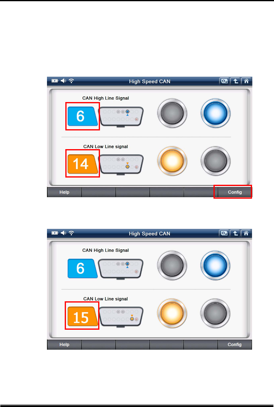
C. According to the Hi-Speed CAN-Bus standard protocol, the CAN-High communication line is
assigned to Pin 6 and the CAN-Low line is assigned to pin 14 of the OBD2 socket as default.
If the car is not complying with the standard, therefore the actual communication lines are
assigned to the different pins, please select “Configuration” and change the settings
accordingly.
[ Default Setting ]
[ Settings Changed: CAN-Low assigned to pin 15 ]
G-scan2 User Manual
54
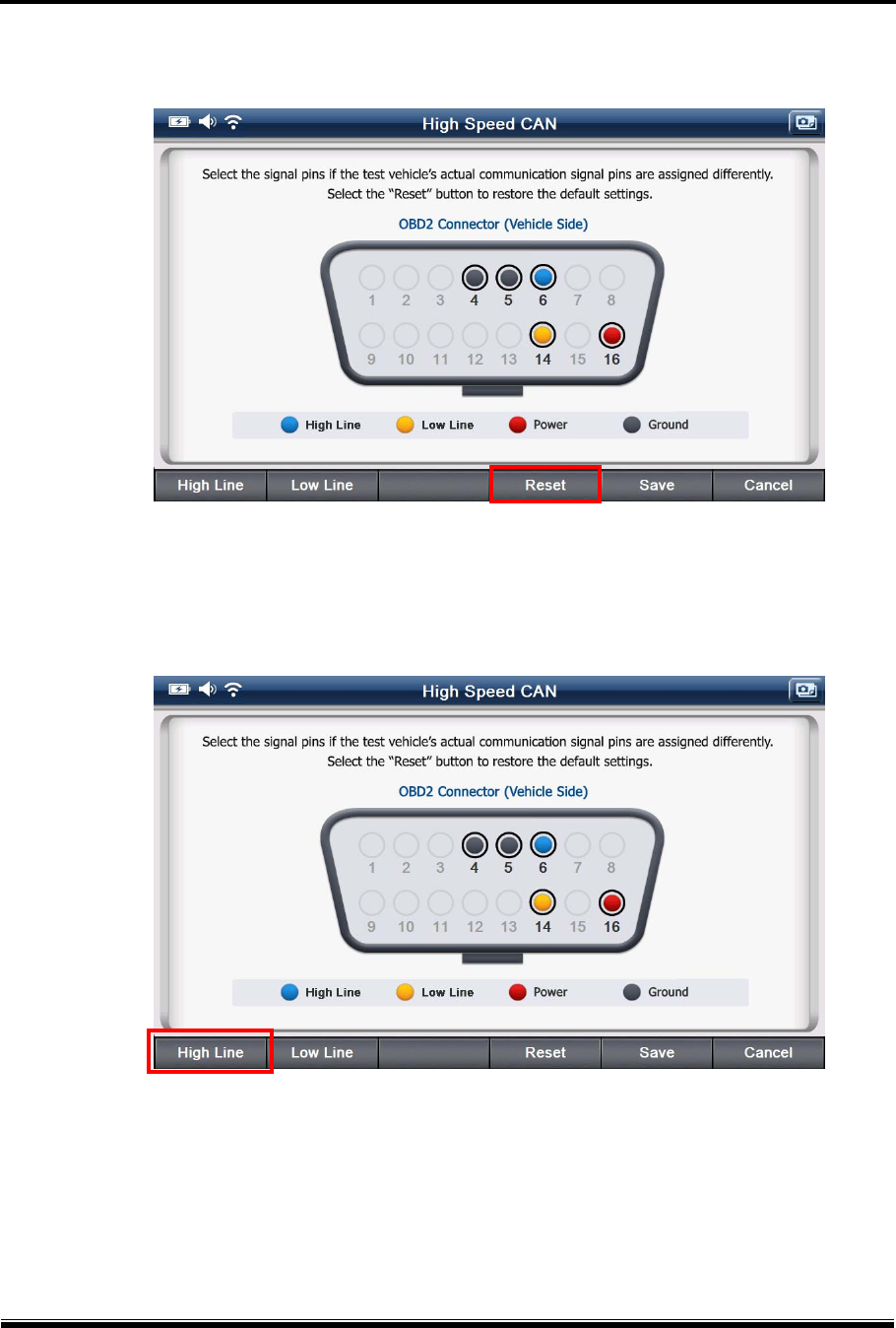
Selecting “Reset” will restore the default settings.
[ “Reset” for default setting restoration ]
D. Interactive menu for changing the settings follows when “Configuration” is selected as shown
below. Select “High Line” to select the pin assigned for CAN-High communication line.
When the custom pin assignment is completed, select “Save” to save the changes.
G-scan2 User Manual
55
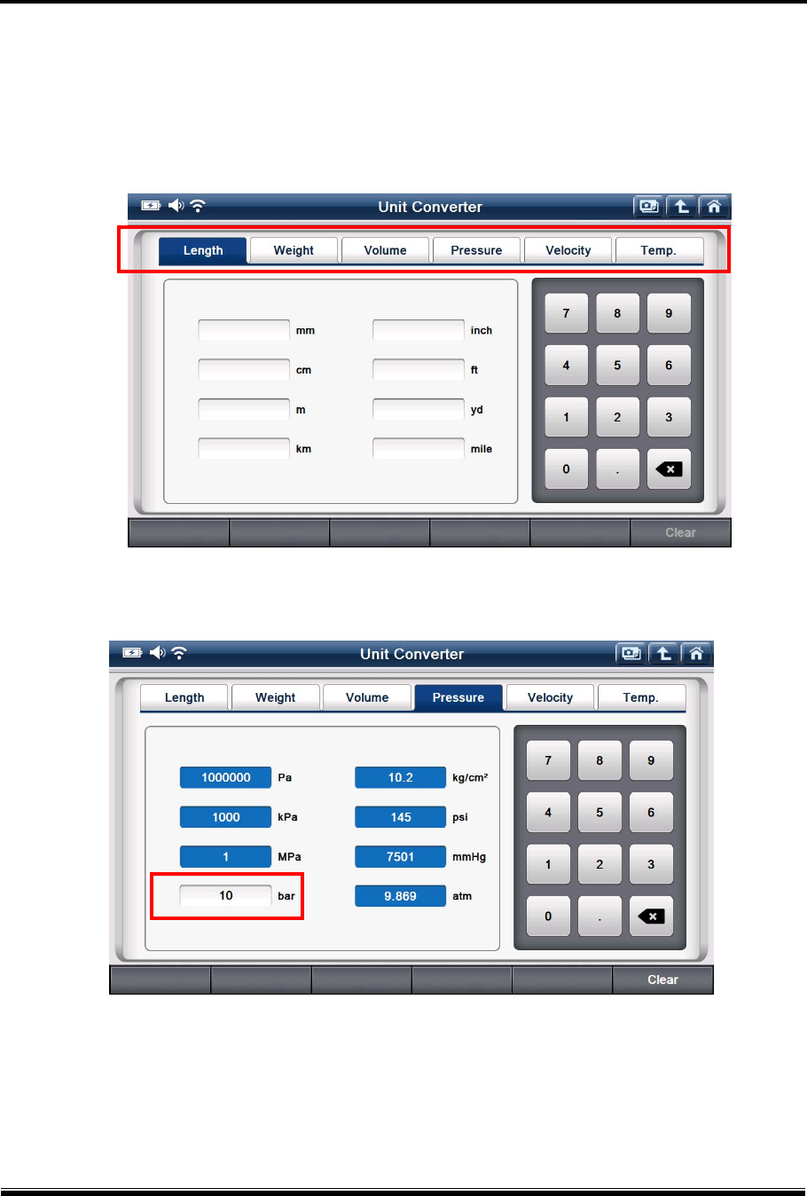
3-2. Unit Converter
This is a utility function used for converting the length, weight, volume, pressure, speed and
temperature readings to the different measuring units.
[ Unit Converter Menu ]
[ Unit Conversion – Different pressure measuring units converted from 10 bar ]
G-scan2 User Manual
56
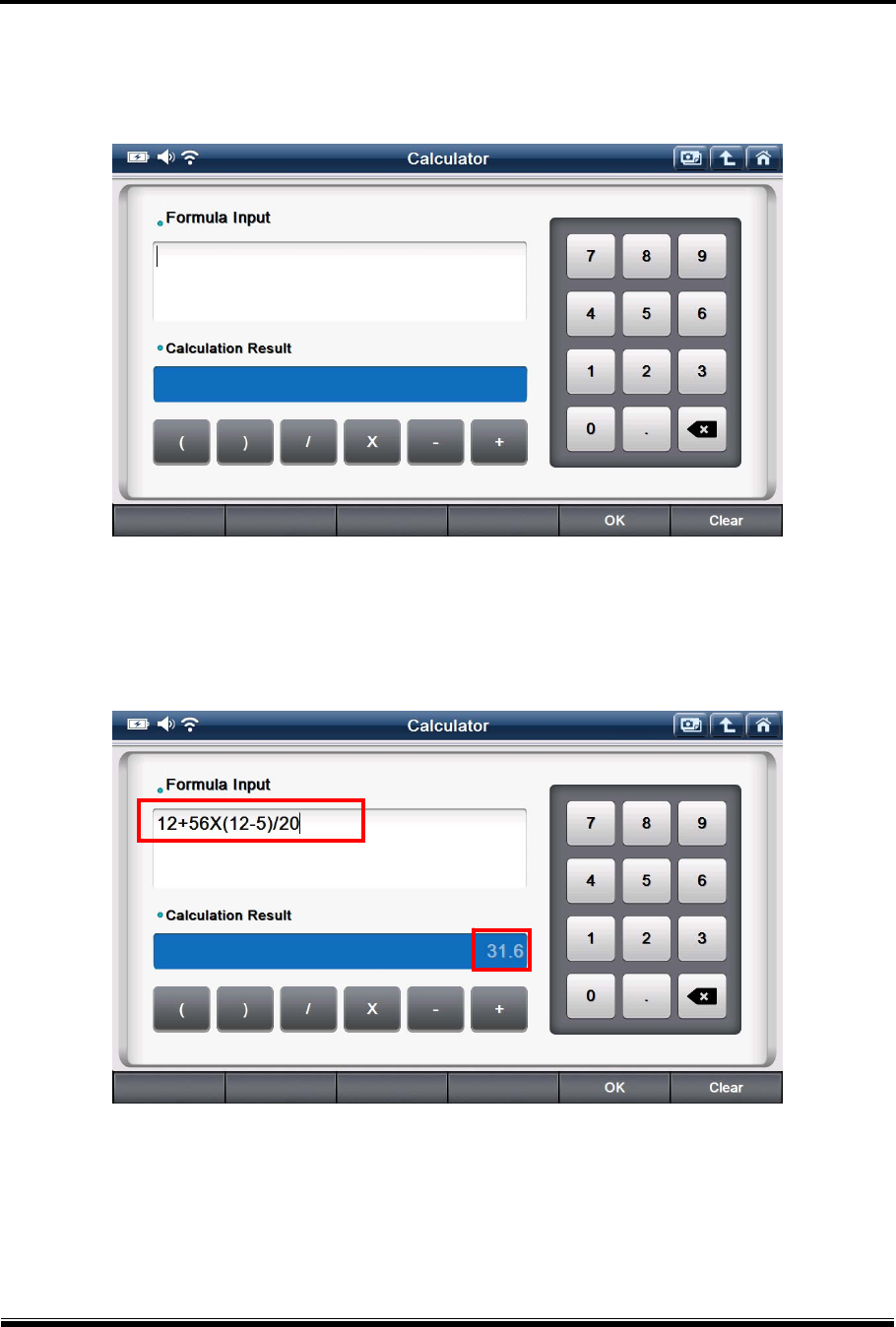
3-3. Calculator
This is a utility function that works like a simple calculator.
[ Calculator ]
The difference from an ordinary calculator is that you can type in the lengthy formula to get the
result.
G-scan2 User Manual
57
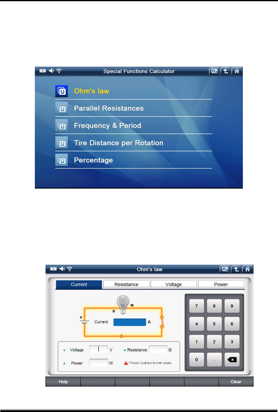
3-4. Special Functions Calculator
This is utility that offers a set of functions that are used frequently at the workshops, which
include Ohm’s law, parallel resistance, frequency/duty cycle, distance per tire rotation and
percentage calculation.
[ Special Functions Calculator Menu ]
A. Ohm’s Law
This function is to get the value you want from the given data with correlation among
Amperage, Voltage, Resistance and Wattage according to the Ohm’s law.
G-scan2 User Manual
58
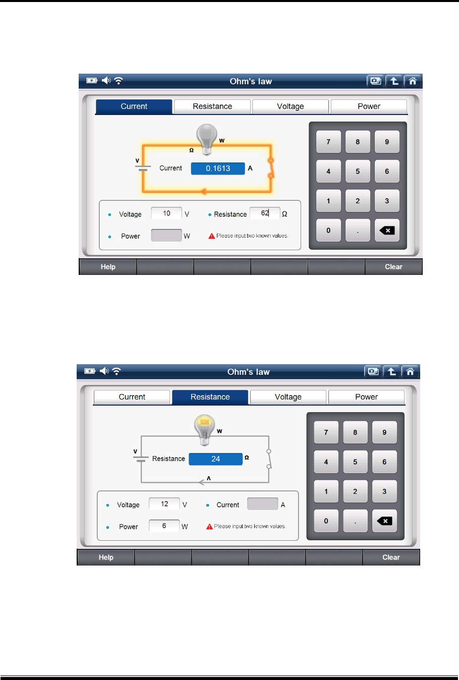
a. Amperage
Input any known 2 values of Voltage, Resistance and Wattage, then Amperage is calculated.
[ Example. Amperage Calculation ]
b. Resistance
Input any known 2 values of Voltage, Amperage and Wattage, then Resistance is calculated.
[ Example. Resistance Calculation ]
G-scan2 User Manual
59
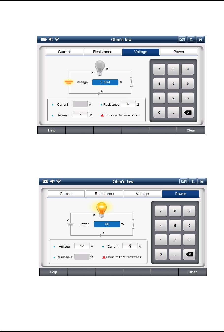
c. Voltage
Input any known 2 values of Resistance, Amperage and Wattage, then Voltage is calculated.
[ Example. Voltage Calculation ]
d. Wattage
Input any known 2 values of Voltage, Resistance and Amperage, then Wattage is calculated.
[ Example. Power Calculation ]
G-scan2 User Manual
60
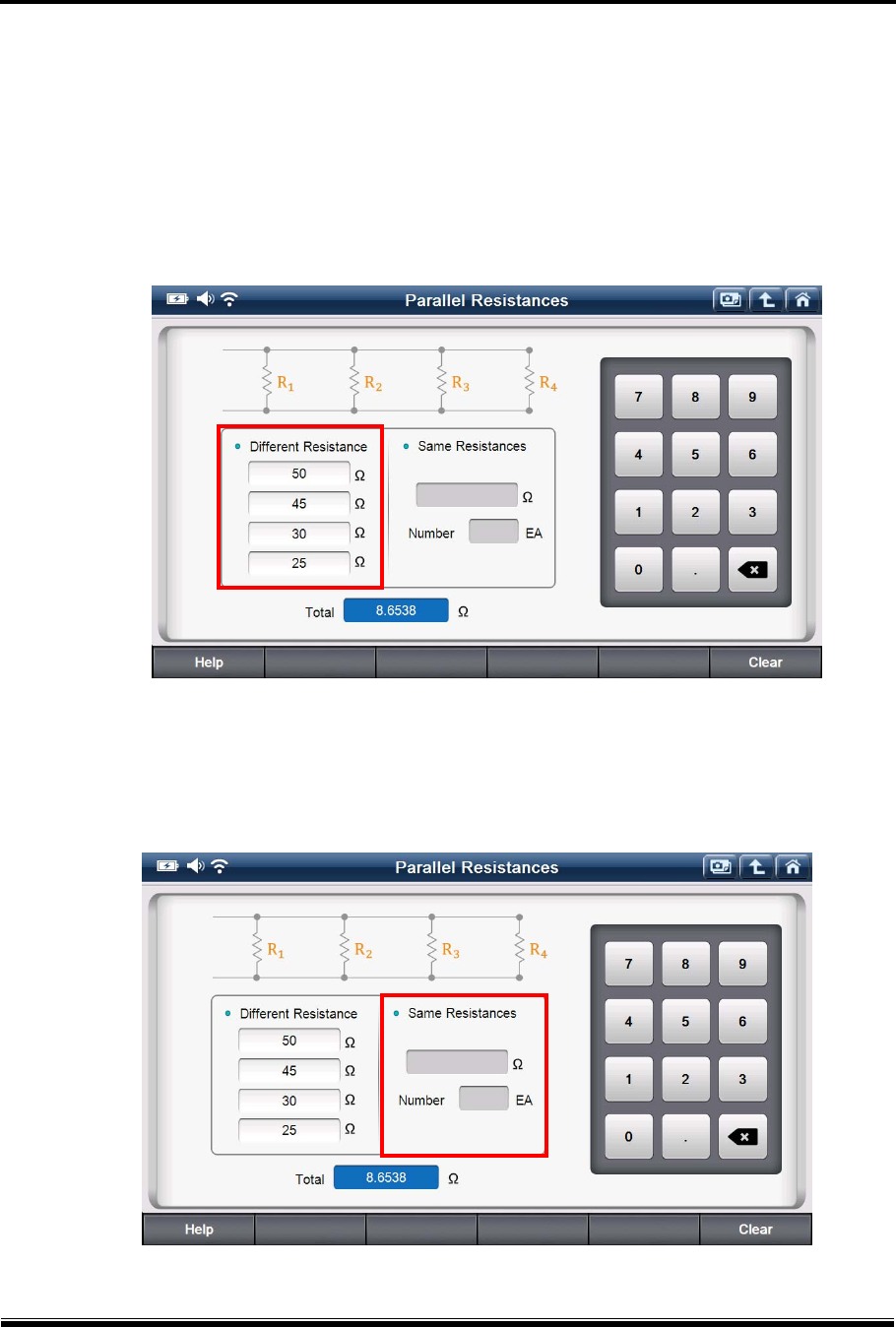
B. Parallel Resistance
This function helps the user calculate the combined resistance of all resistors connected in
parallel in the circuit.
The parallel resistance is calculated by typing in the resistance values of up to 4 resistors
connected in parallel if the resistors have different resistance values. For more than 5
resistors, please get the parallel resistance for the first 4, and then input the result and the
more resistance values to get the final result.
[ Parallel Resistance – individual resistance value input ]
If the resistors are of the same resistance values, type in the value and the number of
resistances to calculate the total parallel resistance.
[ Parallel Resistance – Multiple resistances of same value ]
G-scan2 User Manual
61
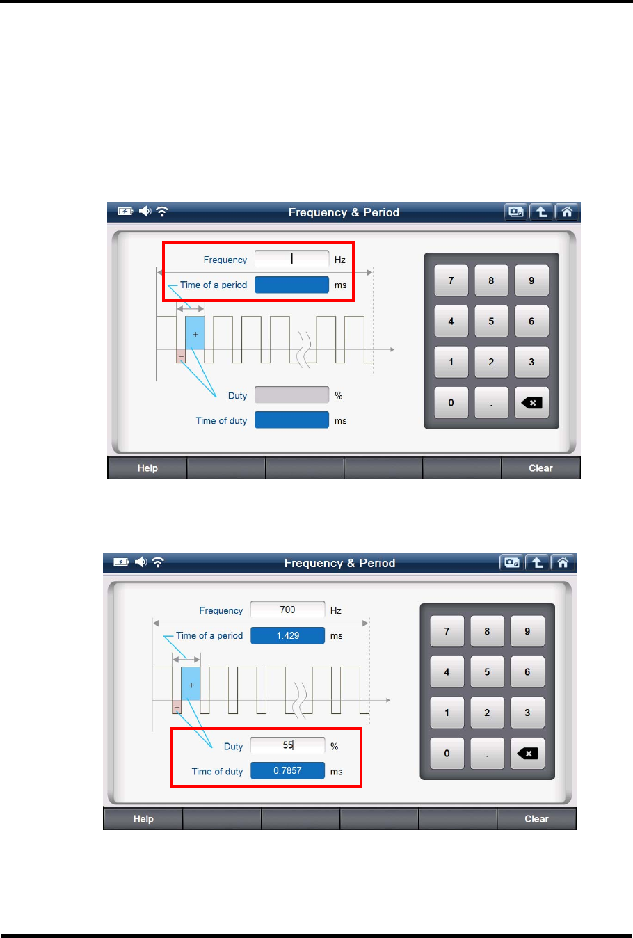
C. Frequency and Period
This function helps the user calculate the duration of one cycle according to the frequency
and duty. While frequency means “working numbers per second”, this function converts it to
“duration of each work”.
[ Frequency and Period. Ex. Duration of a cycle ]
[ Frequency and Period. Ex. Duration of duty ]
G-scan2 User Manual
62
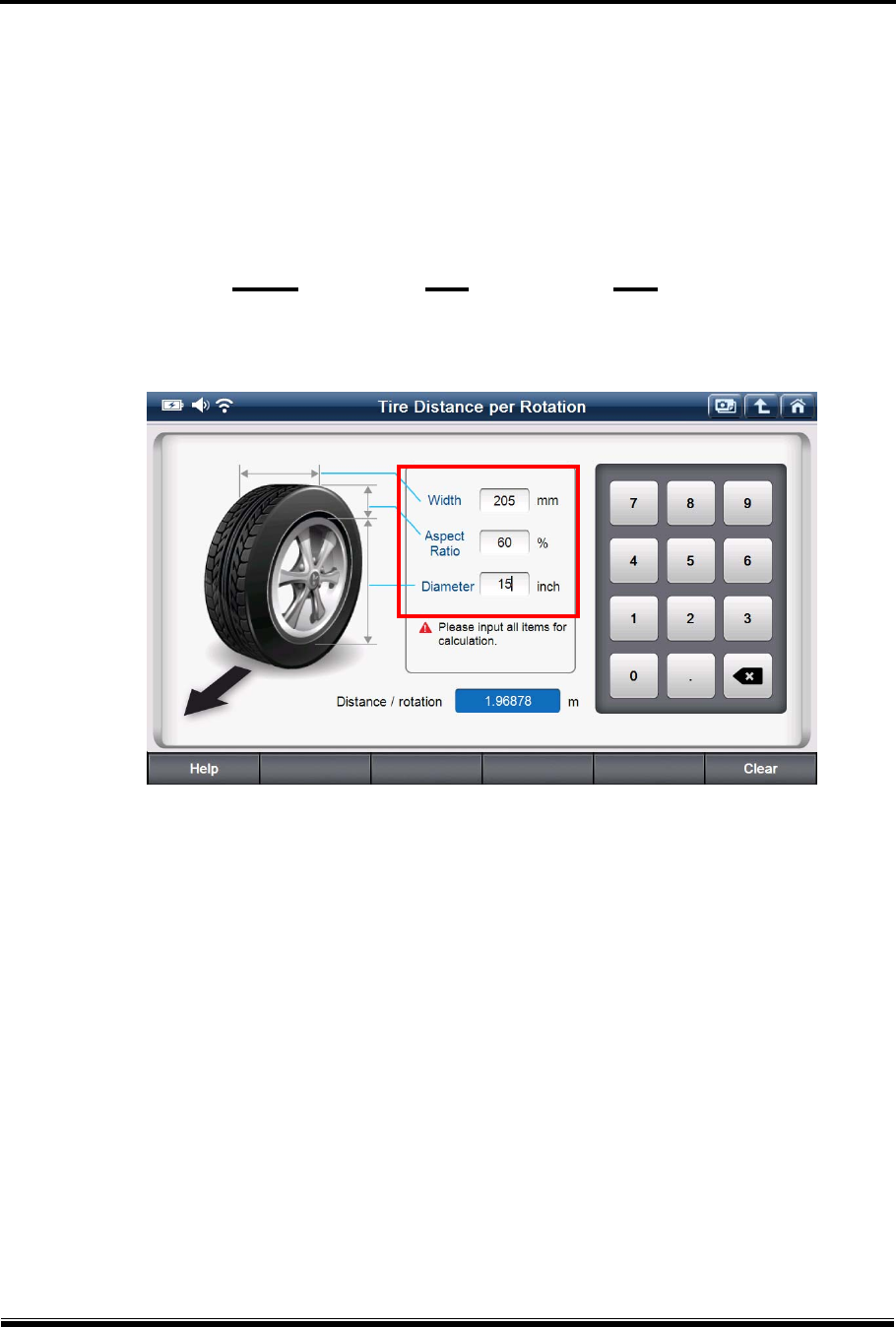
D. Tire Distance per rotation
This function is used for calculating the distance traveled when a tire revolves one time based
on the width, flatness ratio and inner diameter that can be checked on the surface of any tires.
205 / 60 R 15
Width Flatness Ratio Inner Diameter
[ Distance per tire revolution ]
G-scan2 User Manual
63
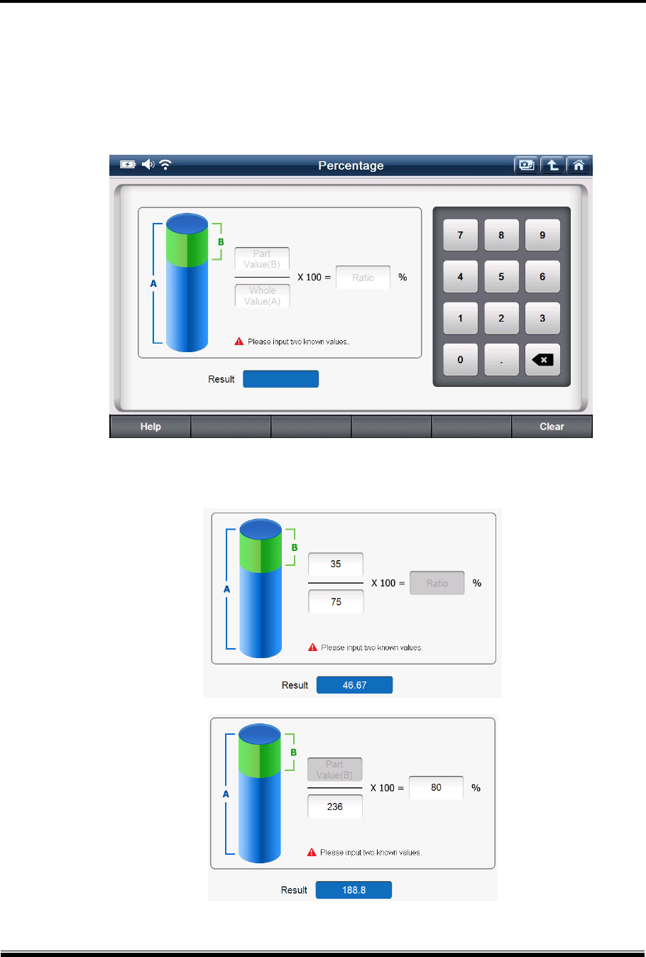
E. Percentage
This function calculates the one out of the other two input variables among Total Value,
Percentage and Partial Value.
[ Percentage Calculation ]
G-scan2 User Manual
64
Bottom Menu
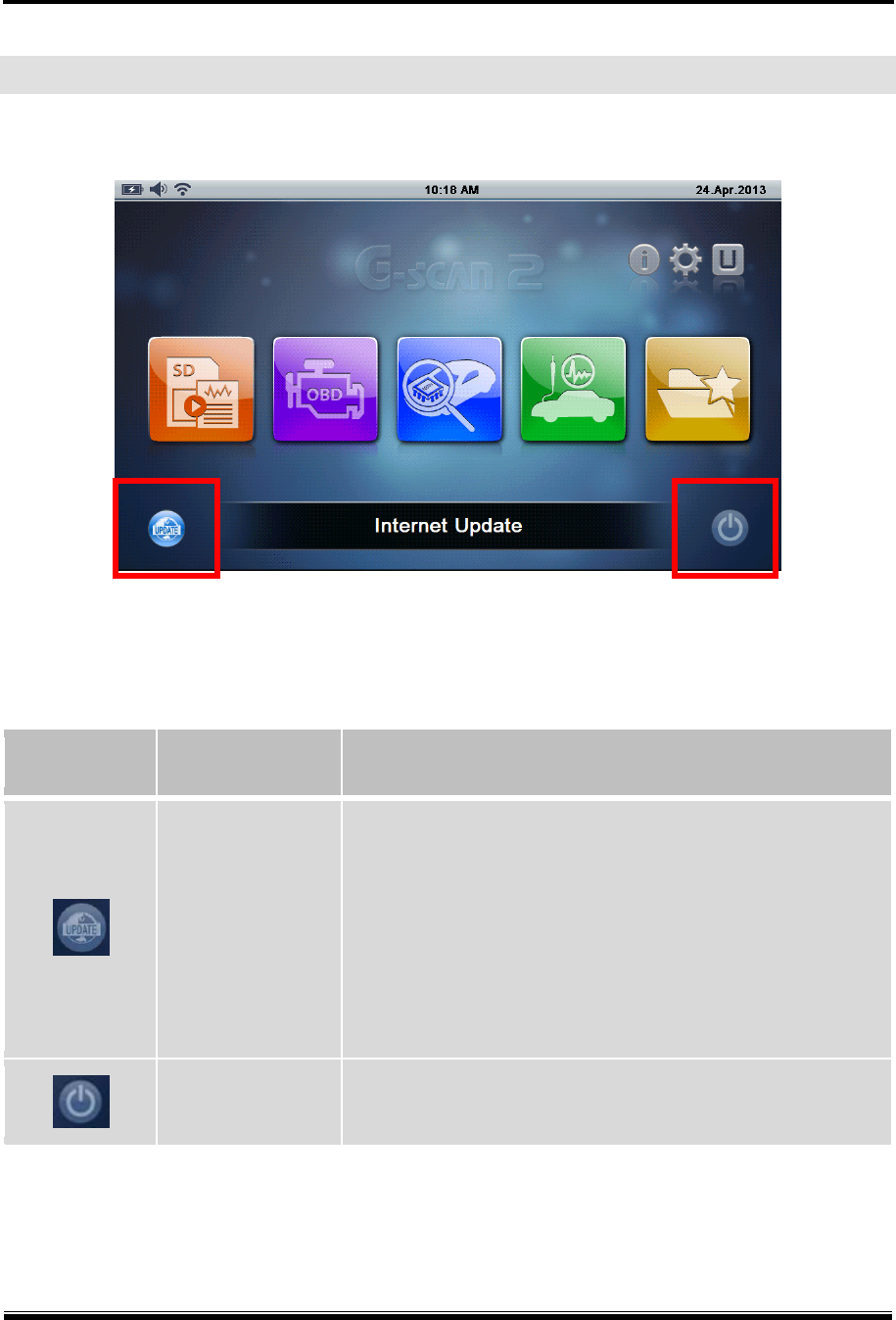
The bottom menu includes the buttons for Internet Update and Power Control.
[ Bottom Menu ]
Icon Title Description
Internet Update
Activates Internet Quick Update function.
G-scan2 needs to be registered on GIT’s server before
using this function and connected to internet through WiFi
networking.
Software for just one brand can be downloaded at a time
for this quick update function. Use of PC Utility is
recommended for downloading multiple brands
Power Control Switches G-scan2 to the Stand-by mode after 5 seconds.
G-scan2 User Manual
65
1. Internet Quick Update
G-scan2 software update is released every 3 months, and the minor patches can be
released in response to customer feedback more frequently as needed. G-scan2 needs to
be updated of its software to add the new features for extending the coverage for more
brands, models and functions as well as the improvement of the product performance.
G-scan2 internet update can be done in 2 ways:
- Download by Direct WiFi Connection
- Download using PC Utility
1-1. Quick update by Direct WiFi Connection
Utilizing the onboard WiFi module, G-scan2 can access to GIT’s update server directly
through internet, check the available updates, select and download the update files.
All these operations can be done on the G-scan2 base unit.
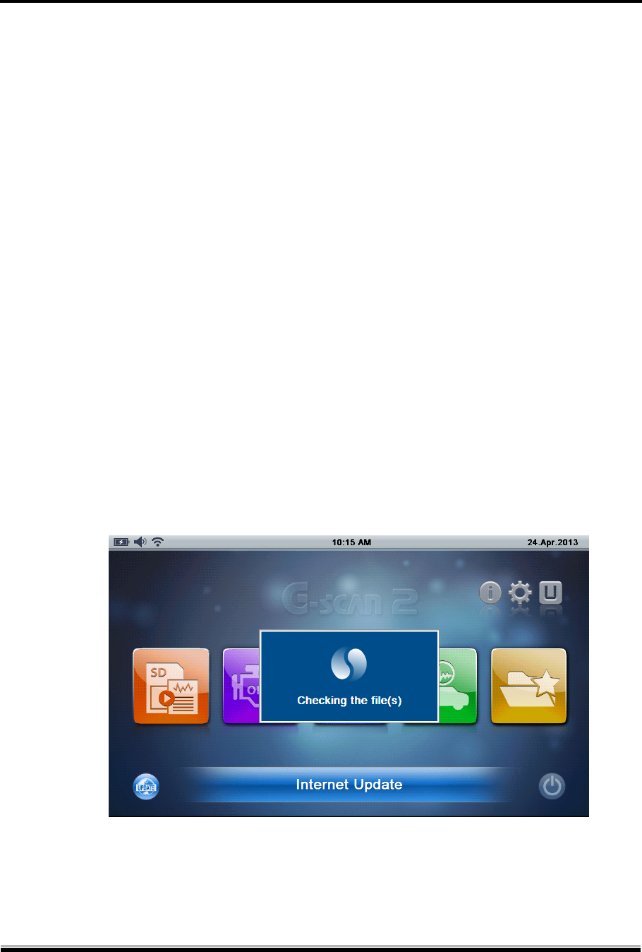
A. Please make sure that the G-scan2 is connected to the internet through the WiFi network.
Select Internet Update icon in the bottom left of the main menu, then the internet update
function is initiated.
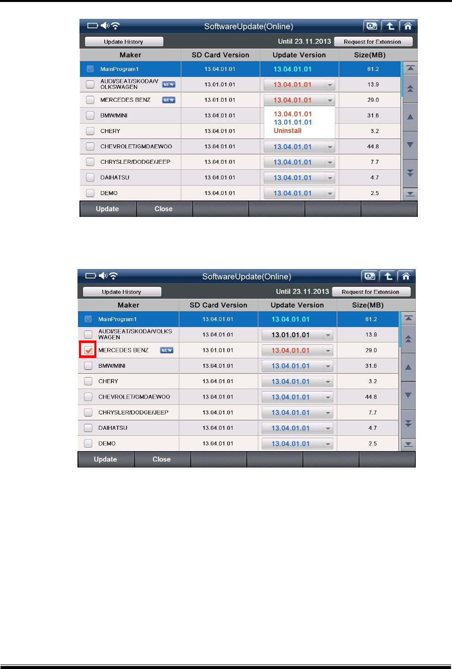
B. Check the availability of new updates.
“New” icon represents that the new update is available for the car manufacturer.
G-scan2 User Manual
66
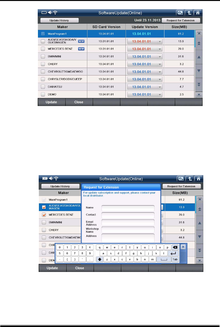
If the update subscription has been expired, no car manufacturers will be listed.
In this case, please check the Expiry Data information provided in the upper right side of the
screen and contact your local distributor for the renewal or extension of the G-scan2’s
update subscription. Or, simply select the “Request for Extension” button in the top right
corner, fill in the pop-up query with your contact information and select “Confirm”, then the
request will be sent to your local distributor automatically.
The download server may offer multiple versions for each vehicle brand, therefore you can
also select the older version if available in case you do not like the new features and want to
restore the known best version.
G-scan2 User Manual
67
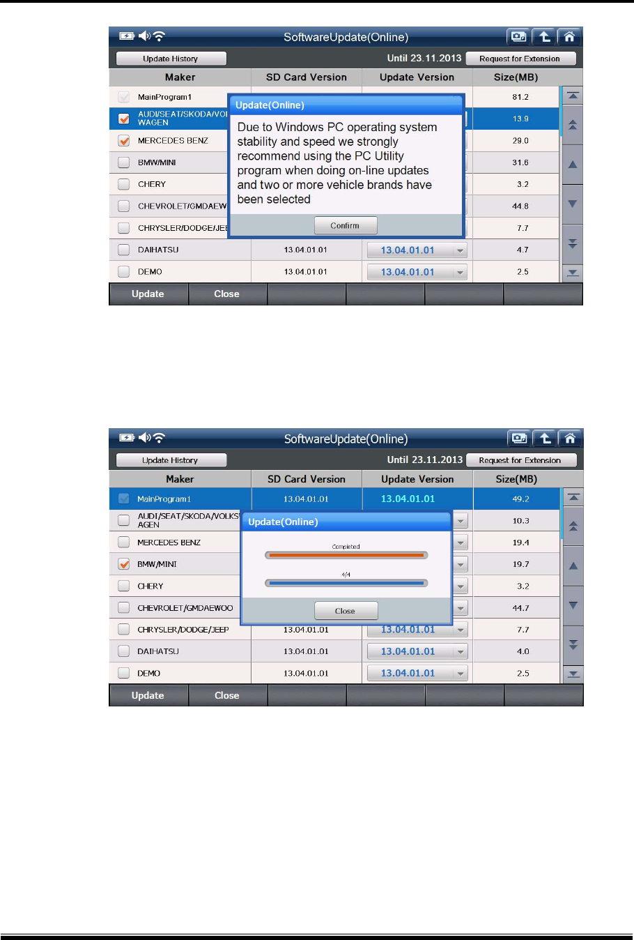
C. Select the car manufacturer by ticking on the check box.
D. Even though G-scan2 is running on the latest Windows CE system, when compared with
PC’s Windows operating systems, it shows relatively limited stability and performance for
conducting heavy operations like downloading, extracting, deleting and copying the big size
files.
Direct WiFi download is allowed for downloading the programs for 1 vehicle brand at a time,
and when the 2nd car manufacturer is selected from the menu, the warning message will pop
up as shown below.
Please use the PC Utility program when doing on-line updates for more than 2 car
manufacturers.
G-scan2 User Manual
68
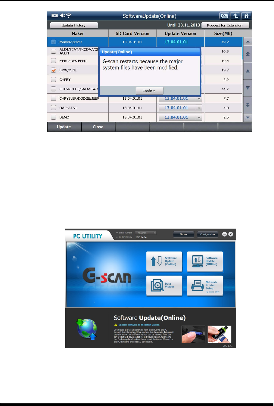
E. Select “Update” button in the bottom left corner, then G-scan2 begins downloading the
selected files from the server. Software update is consisted of total 4 steps – downloading,
deleting, copying and verifying and the progress is indicated as shown below.
F. Select “Close” button when the software update is completed.
In most cases, G-scan2 needs to restart to apply the newly downloaded updates.
Select the “Confirm” button to let the G-scan2 restart its system.
G-scan2 User Manual
69
1-2. Download using PC Utility
In case the WiFi facility is not available or downloading the files for 2 or more car
manufacturers is required, PC Utility needs to be used for updating the G-scan2 software.
Please refer to the Chapter 4. G-scan2 PC Utility in this manual for more details.
G-scan2 User Manual
70
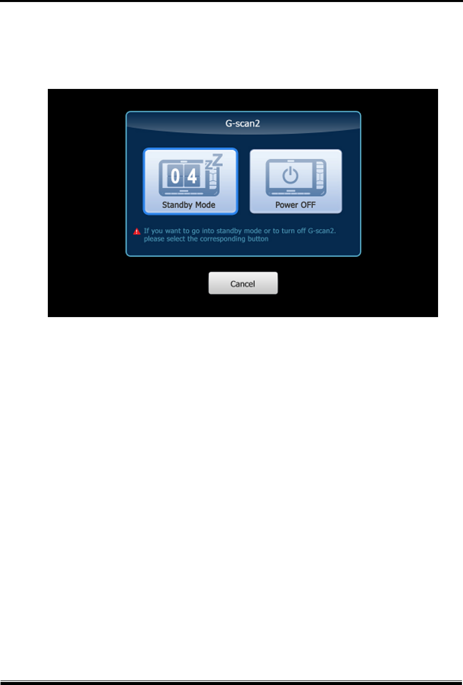
2. Power Management
Selecting this button works primarily the same as pressing the [Power] key shortly.
When selected, the following window pops-up for further selection – sleep mode or complete
power off.
Select Standby Mode button to let the G-scan2 enter into the hibernating mode, then G-scan2 will
restart instantly by a key stroke or a touch on the screen, without the boot up sequence.
Select Power Off button to turn the G-scan2 completely. G-scan2 will make a cold start taking
the normal boot up sequence when the [Power] key is pressed.