Users Manual
User’s Manual
- 1 -
Check before use
Read me first ----------------------------
Introduction of G-scan ----------------------
Safety Warnings and Cautions before Use ------
G-scan Configuration
Specification ----------------------------------
Introduction of component ----------------------
Introduction of function -------------------------
Basic Use of G-scan
Power supplying ----------------------------
Power ON/OFF ----------------------------
Description for Main Component of H/W -----------
Description for Main Component of S/W Screen ------
Connecting the DLC cable ---------------------
Self Test Adapter connection ------------------
Configuration
Setup ------------------------------------
User Information -----------------------------
Version -----------------------------------
Self Test ----------------------------------
Contents
Check before using Module NO: A-00-001

User’s Manual
- 2 -
Vehicle Communication Function
System Select --------------------
Fault Code Searching ------------
DTC Analysis ----------------------
DATA Analysis ------------------
Actuation Test ---------------------------
Vehicle S/W Management ---------
ECU Upgrade ------------------------------
OBD-II Function (CARB OBD-II) -----------------
Flight Recording --------------
PC Communication
Software Installation --------------------------
Operating Program --------------------------
Appendix
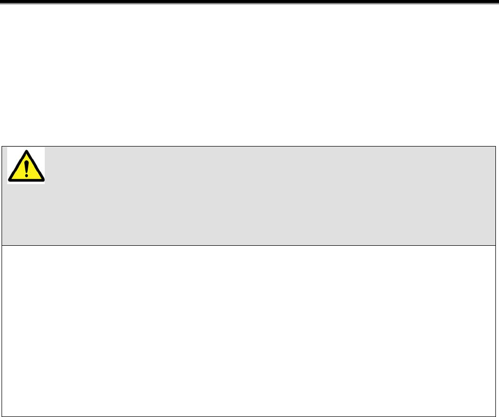
How to install Optional Items --------------------
O/S & Bootloader Update --------------------
G-scan and Peripherals Limited Warranty ----------
Disposal of Old Electrical and
Electronic Equipment
--------------------
Module NO: A-00-001

User’s Manual
- 3 -
User’s Manual
- 4 -
Read me first
Check before use Module NO: A-00-002
Introduction
Thank you for purchasing G-scan. This manual describes the basic
information for using G-scan. Before using G-scan, please read this
manual to be familiar with important information.
Copyright
Global Information Technology Co., Ltd copyrights this Manual. All rights
reserved. No part of this manual may be reproduced in any form without
the prior written permission of Global Information Technology Co., Ltd.
No patent liability is assumed with respect to the use of the information
contained herein.
G-scan is registered trademark or trademark of Global Information
Technology Corporation in the United States and/or other countries.
ⓒ2007 Global Information Technology Co., Ltd. All Right Reserved.
Disclaimer
G-scan specifications and manual are subject to change without prior
notice. Global Information technology Co., Ltd. assumes no liability for
the products, which GIT do not produce.

User’s Manual
- 5 -
Introduction of G-scan
Check before use Module NO: A-00-003
Overview
Comparing with the conventional diagnosis equipment, the interface of
G-scan is configured to be easily operated. Anyone can easily use the
G-scan to maintain the vehicle with maximized service efficiency.
z Input using the Touch Screen
Without complicated button operation, you can select menu and
function on the screen directly. You can use diagnosis equipment
easily.
z 5.6″ Color TFT LCD
Adapting the 5.6″ large size Color TFT LCD, various data can be
shown on the same screen at the same time.
z TPMS (Option)
Embedding with TPMS module, it is possible to access to the TPMS
sensor installed in the vehicle with wireless communication.
z USB communication interface
Using the USB communication interface, it is possible to connect with
the diagnosis newly developed in future easily..
User’s Manual
- 6 -
Safety Warnings and Cautions
Before Use
Check before use Module NO: A-00-003
This section contains WARNINGS and CAUTIONS for safe usage of
G-scan Before use, the user should read the following information.
z The G-scan should be secured in a safe location when operated in
the vehicle to avoid interference with other vehicle equipment.
z Only use the specified adapters and cables when connecting the G-
scan module. (7~35VDC).
z Ensure all cables are properly connected during operation. Do not
disconnect communication cable or power cables unless finished with
the equipment.
z Do not disassemble the G-scan module.
z When updating G-scan, connect the external power (AC/DC adaptor)
to supply stable power.
z Ensure that the module is installed in a safe and secure location to
avoid interference with other vehicle equipment.
z Use only genuine accessory parts supplied by GIT.
WARNING
This indicates incorrect handling may result in a
major accident involving death or serious injury.

User’s Manual
- 7 -
z Never connect the device to equipment rather than vehicles.
z Products are to be used within the right temperatures. (Refer to
Specifications)
z Products are to be stored within the right temperatures. (Refer to
Specifications)
z Use GIT products for their original purpose only.
z This product is designed for technicians with proficient skills therefore
all users must digest manuals fully before using the product.
z Users have their own responsibility for Product damages, fire hazards
and emitted gas caused by users with no full understanding of the
Cautions and other information stated in the manual.
z GIT products should never be tested or repaired by any one rather
those authorized service technicians by GIT.
z When exchanging rechargeable battery, comply with the method
described in this manual by reading before exchanging it.
z Use only rechargeable battery supplied from GIT.
z Do not disconnect the rechargeable battery at one’s discretion.
z Be careful that the rechargeable battery is not wet in water.
z Do not put the rechargeable battery near the fire.
z Do not impact to or prick the rechargeable battery with sharpen object.
z Don not put the rechargeable battery into the microwave oven or high
pressed vessel.
z Do not throw or apply with physical impact to the rechargeable battery.
Module NO: A-00-003
User’s Manual
- 8 -
z Be careful that the terminals of rechargeable battery are not shorted.
z If the rechargeable battery makes any abnormal condition such as
odor, heat, deformation or discolor, do not use it. If you are charging
or using the battery, stop the operation and remove the battery
immediately.
z Do not reverse the positive(+) and negative(-) terminals.
z Do not connect the battery directly to wall outlets or car cigarette-
lighter sockets.
z Do not put the battery into a fire or apply direct heat to it.
z Do not short-circuit the battery by connecting wires or other metal
objects to the positive(+) and negative(-) terminals.
z We GIT are not responsible for products other than products produced
by GIT.
CAUTION
This indicates incorrect handling may lead to
injury or damage to properties. Under certain
conditions more serious consequences may
result.
z Do not drop the G-scan.
z Do not place any objects (tools, manuals, etc.) on the G-scan.
z When connecting cables under the hood, secure the cables to avoid
damage caused by hot or moving parts.
z When connecting the DLC cable, check the locking device.
z Observe correct polarity when connecting the power supply cable.
z Properly store all components when not in use.
Module NO: A-00-003

User’s Manual
- 9 -
z Do not use cables as carrying handles.
z Do not store products in places where
Extremely high or low temperature (Refer to feature of products)
Extremely high or low humidity (Refer to feature of products)
Inside a vehicle during summer season for a long time
z Exposed to direct rays
z Avoid a shock or vibrations or under heavy weight.
z Avoid a shock or vibrations during shifting.
z Keep products away and store from moisture.
z Keep products away from flammable substances or places where
fierce static electricity can occur.
z Products and accessories are not to be coated or painted with
chemical substances or acid that can corrode the equipment.
z Do not expose the equipment to X-ray or Microwave. This might cause
severe damage to the equipment.
z When inserting SD memory, check the direction.
z When supplying electric power to G-scan with 220/100V source, use
only the adapter supplied with this product.
z When using touch screen, use the specified stylus pen only. If you use
other sharp or keen object on the touch screen, it can be damaged
severely.
z Do not store the battery in the hot area. It may reduce the service time
of battery.
z If the G-scan with battery pack has to be stored for a long time(over 3
months), the environmental condition(Temperature: 23±5℃, Humidity:

User’s Manual
- 10 -
65±20%RH, Battery Level Indicator: 2 of 3 levels) should be observed.
z When your eyes contact battery liquid, do not rub your eyes, but clean
out them with fresh water. Contact doctor immediately.
z Do not expose the LCD to moisture or water.
z When LCD is broken, the liquid crystal material will be flown out. Do
not contact liquid crystal. If you contact it, clean it out immediately
with soap water.
z When LCD surface is contaminated, clean it using soft clothes with
alcohol.
z Do not contact volatile material except alcohol to LCD surface.
z Do not lay any heavy object down on LCD panel.
z After using for a long time, conduct zero calibration to the touch
screen.

User’s Manual
- 11 -
User’s Manual
- 12 -
Specification
G-scan Components Module NO: A-01-001
Main Specification
Item Specifications
Micro Controller ARM9 (S3C2440A) @400MHz
NOR Flash Memory 16MB
NAND Flash 64MB
Memory
SDRAM Memory 32MB×2
External Memory 1GB (up to 4GB)
0℃~45℃(32℉~113℉) : Battery Charging
Operating 0℃~50℃(32℉~113℉) : Battery Discharging or
without Battery
Temperature
Storage
-10℃~70℃(14℉~158℉)
(Refer to cautions of manual)
Noncondensing @ 0℃~10℃(32℉~50℉)
90%RH @ 10℃~30℃(50℉~86℉)
Operating
70%RH @ 30℃~50℃(86℉~122℉)
Relative
Humidity
Storage
Noncondensing @ -10℃~70℃(14℉~158℉)
(Refer to cautions of manual)
LCD 5.6″ TFT Analog LCD (480 × 234 pixel)
Power ON/OFF Key, Enter Key, ESC Key,
Arrow 4 Keys, Functional 6 Keys
Input Devices
Touch Screen 5.6 ″
User’s Manual
- 13 -
External Lamps 2 Color LED × 3 (Power, DLC, Option)
Sound Buzzer 1 Tone
Battery (*Option) Li-Ion Polymer 2100mAh 1cell
Operating Voltage 7~35VDC
Housing PC + ABS & Rubber Shroud
Dimension 194×129×59 mm
Weight about 900g(Body weight including Battery, TPMS
Pack)
G-scan TPMS
Item Specifications
TPMS radio frequency
Transmission: 125Khz Reception: 315Mhz or
433Mhz
TRW (ASK, FSK)
LEAR (FSK)
TPMS Protocol
Siemens (FSK)
PC SPEC.
Item Specifications
External input/output device USB Host, USB Slave (USB 1.1)
G-scan (Vehicle Communication Interface)
Item Specifications
CAN ISO – 11898, ISO - 11519
K-Line/L-Line ISO-9141, ISO-9141-CARB, KWP-2000
Module NO: A-01-001
User’s Manual
- 14 -
Commercial Veh SAE-J1708, RS-232C
Data/Control Line Melco Pull-Down UART
Added interface
Item Specifications
1. VSS Vehicle Speed Simulation
2.Voltage Output 5~20 VDC
Module NO: A-01-001

User’s Manual
- 15 -
FCC ID: TMGG1PZFMN001
NOTE: This equipment has been tested and found to comply with the
limits for a Class A digital device, pursuant to Part 15 of the FCC Rules.
These limits are designed to provide reasonable protection against
harmful interference when the equipment is operated in a commercial
environment. This equipment generates, uses, and can radiate radio
frequency energy and, if not installed and used in accordance with the
instruction manual, may cause harmful interference to radio
communications. Operation of this equipment in a residential area is
likely to cause harmful interference in which case the user will be
required to correct the interference at his own expense.
CAUTION: Changes or modifications not expressly approved by the
party responsible for compliance could void the user's authority to
operate the equipment.
This device complies with part 15 of the FCC Rules.
Operation is subject to the following two conditions:
(1) This device may not cause harmful interference.
(2) This device must accept any interference received, including
interference that may cause undesired operation.
User’s Manual
- 16 -
Introduction of Components
G-scan Components Module NO: A-01-002
Part Description Qty.
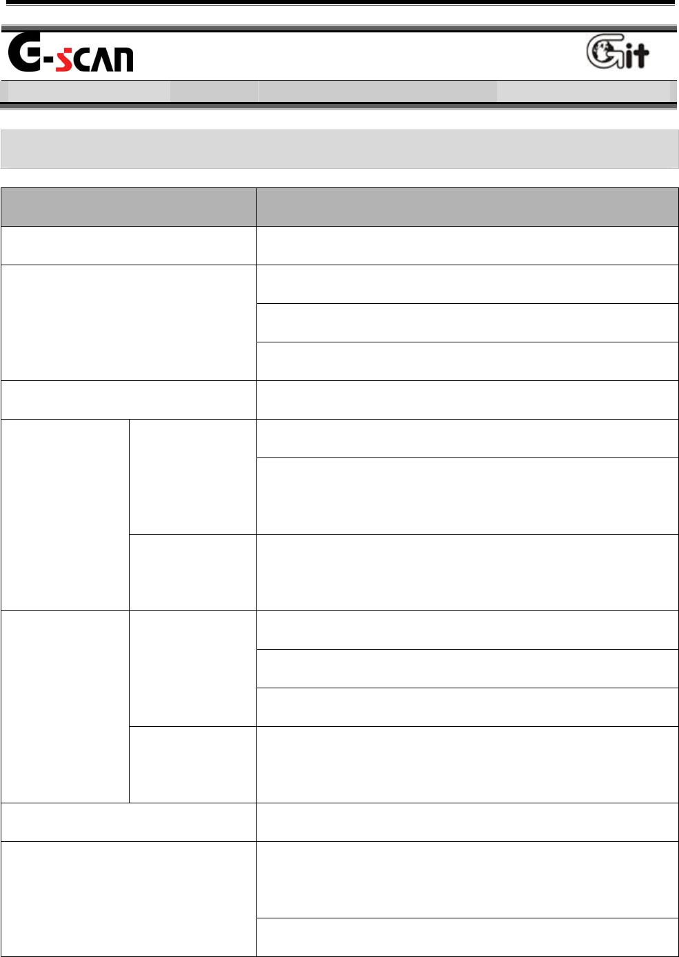
Part Name: G-scan module
P/No:G1PZFMN001
G-scan module comprises of the main module
for vehicle communication and the option pack
(Battery pack, TPMS pack).
1
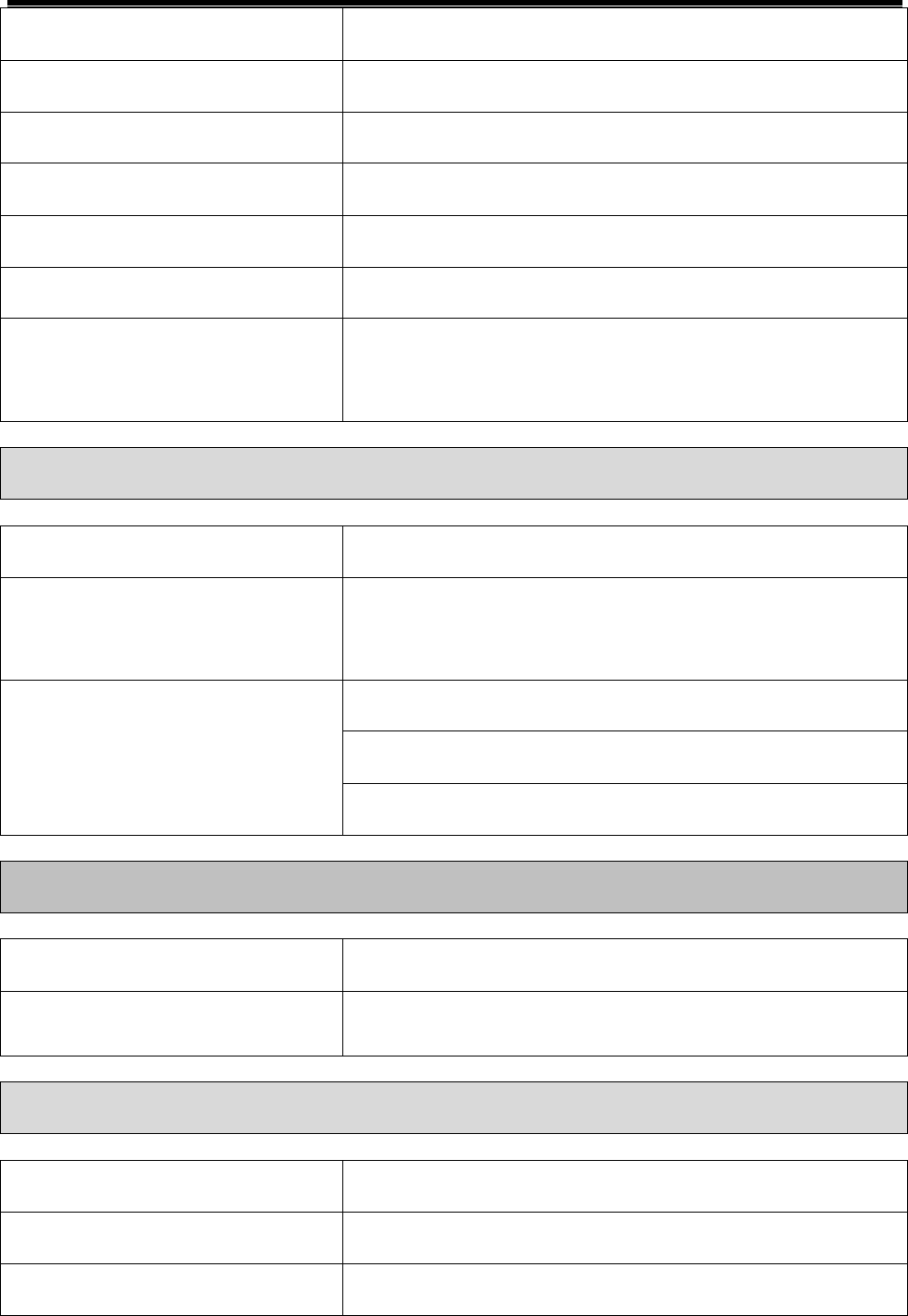
P/Name: Hand Strap
P/No: G1PDDMN002
This is the hand strap for preventing damages
by falling during using the G-scan. 1
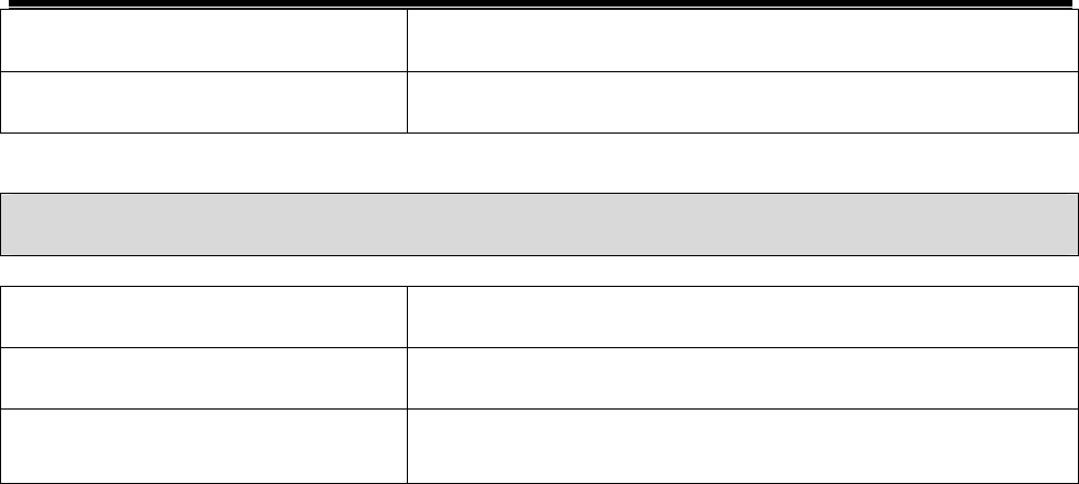
P/Name: String - Stylus
P/No: G1PDDMN003
A spring type string for preventing the stylus
pen from being lost. 1
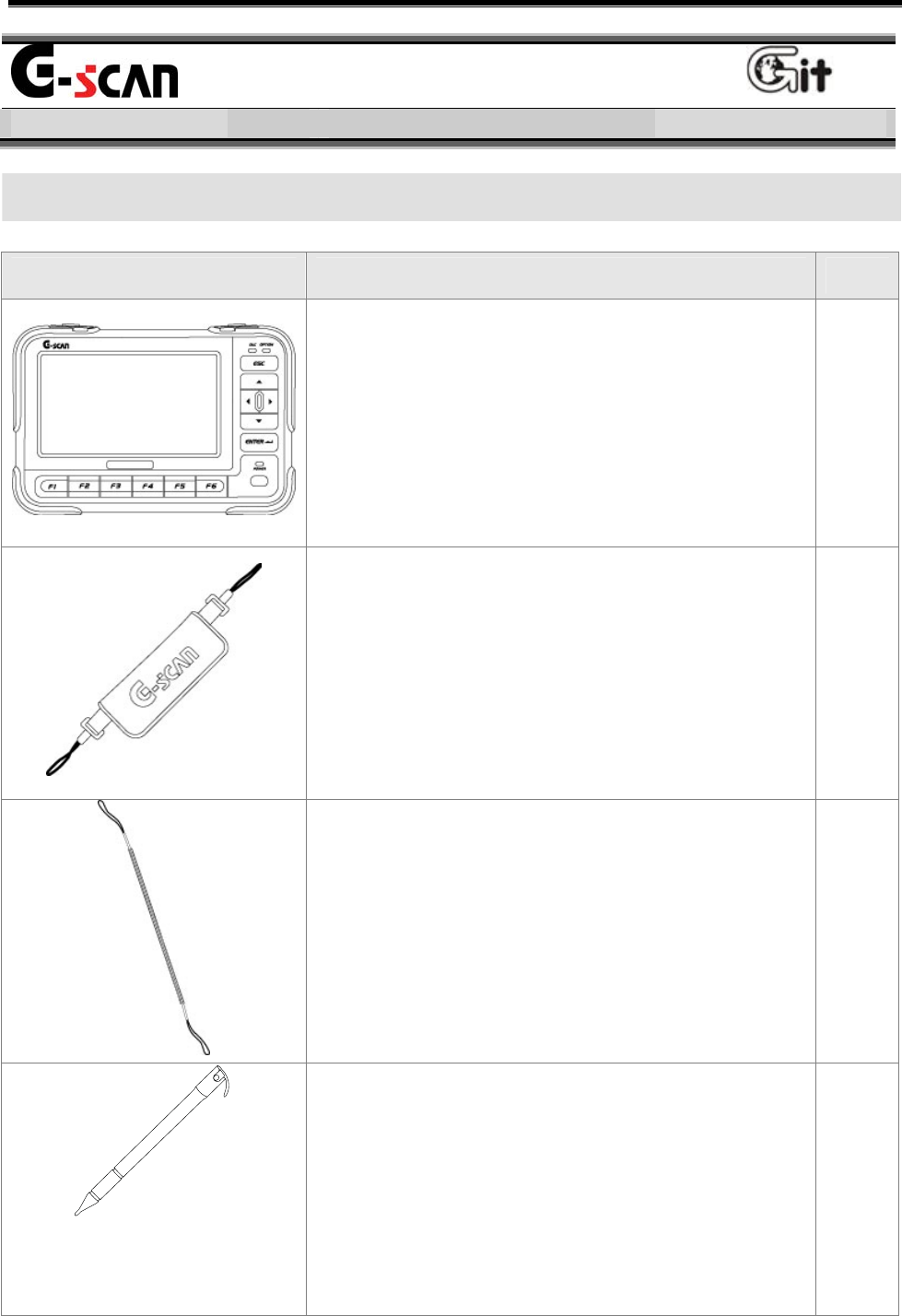
P/Name: Stylus Pen
P/No: G1PDDMK020
The specific tool for operating touch screen of
G-scan. When using the touch screen, use
this stylus pen only.
1
G-scan Hardware Components
User’s Manual
- 17 -
Part Description Qty.
P/Name: CABLE-DLC
P/No: G1PDDCA001
DLC main cable for communication between
G-scan module and (16 pin) OBD-II diagnosis
connector on vehicle. 1
P/Name: User’s Manual
P/No: N/A
The book describing the basic information for
using the G-scan. 1
P/Name: CD (S/W)
P/No: N/A
CD includes the PC utility program.
The PC utility supports the G-scan update and
the G-scan system recovery. 1
P/Name: Adapter[16pin-20pin(R)]
P/No: GHDM-244000
DLC Adapter cable [16pin to 20pin(R)] for
Main DLC cable (P/No: G1PDDCA001) and
20-pin diagnosis connector on vehicle.
20pin (R) connector is GRAY in color.
1
User’s Manual
- 18 -
Part Description Qty.
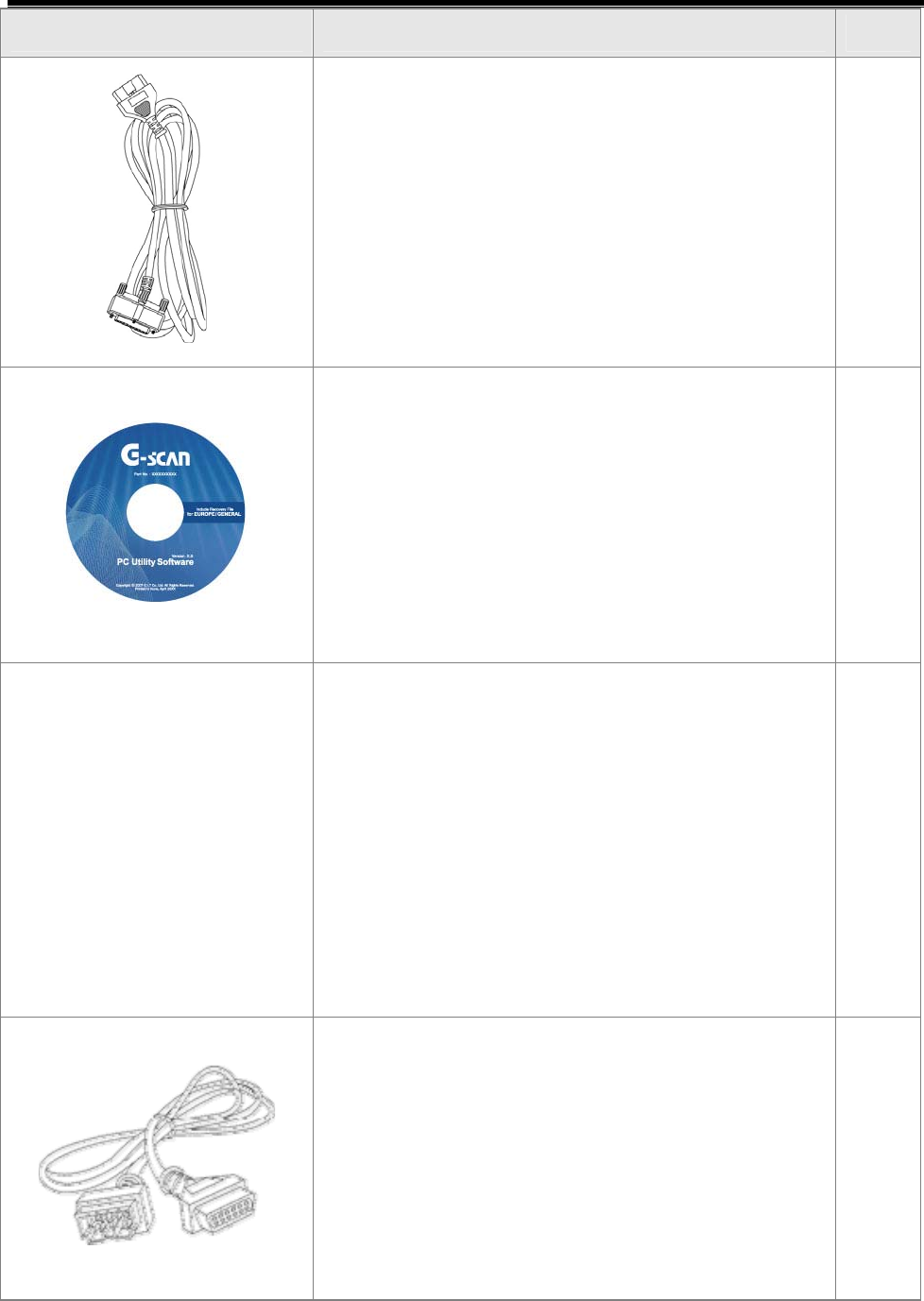
P/Name: CABLE - CIGAR
P/No: G1PDDCA002
It is used for supplying external power to the
G-scan using cigarette lighter terminal.
1
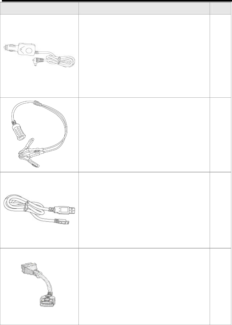
P/Name: CABLE - BATTERY
P/No: GSTA-37210A
The cable for connecting the Cable – Cigar
(P/No: G1PDDCA002) to the battery terminals.
1
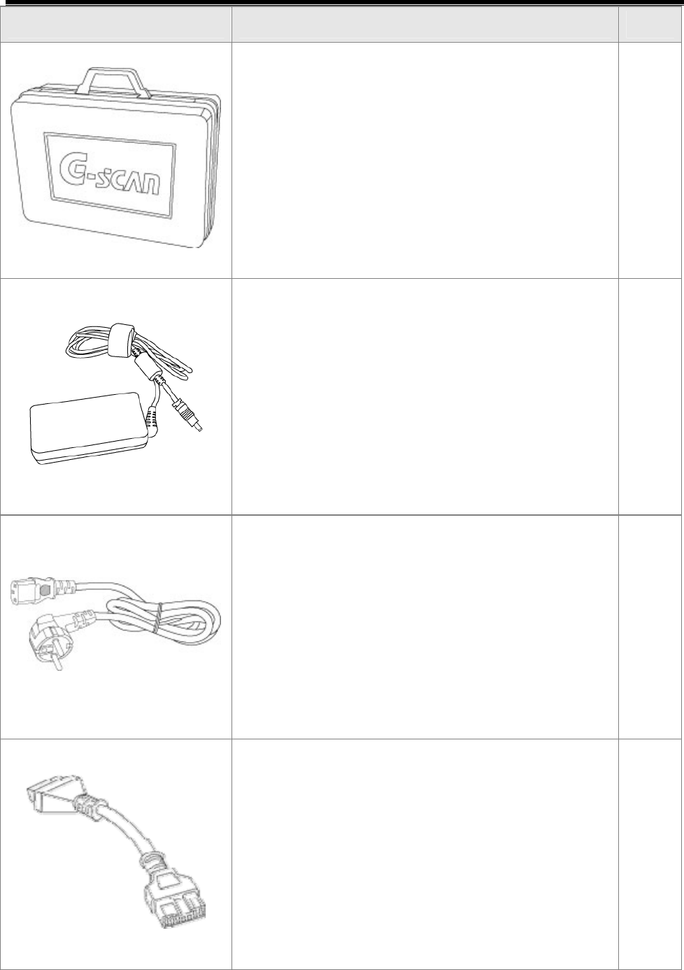
P/Name: CABLE-mini USB(DOWNLOAD)
P/No: G1PDDCA003
Cable for communication between G-scan and
PC(Laptop)
1
P/Name: ADAPTER(Self Test Jig)
P/No: GHDM-24D000
This self-test adapter is used for self-
diagnosis functions that are described in a
separate chapter. Do not use this adapter
except for its specified purposes. For more
information about self-diagnosis, see chapter
(Module: A-02-006) Self-test adapter.
1
User’s Manual
- 19 -
Part Description Qty.
P/Name: Carrying Case
P/No: G1PDDHA001
The case preserving G-scan body and
components. For preventing from being
damaged and lost, G-scan should be stored in
this case after using.
1
P/Name: AC/DC Adapter
P/No: GHDM-260001
Adapter for supplying power to the G-scan
main module from AC power
1
P/Name: AC Power Cable
P/No: GHDM-273000
Cable for AC/DC adapter
The socket plug for AC power cable can be
different depends on each area. Please
purchase the right plug if it doesn’t match with
your country’s electrics specification.
1
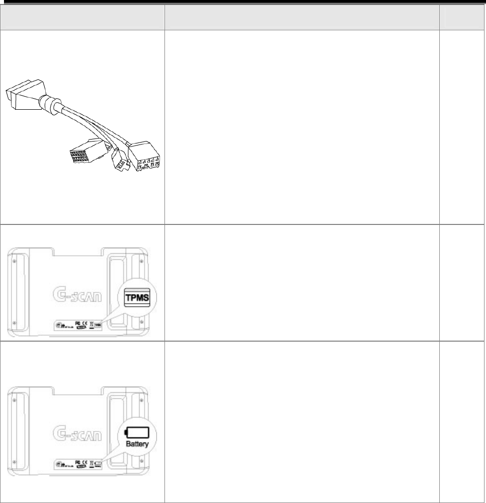
P/Name: Adapter(16-12)
P/No: GHDM-245000
This adapter is connected between Main DLC
cable(P/No: G1PDDCA001) on the G-scan
module and 12pin diagnosis connecter on
some specific vehicles.
1
User’s Manual
- 20 -
Part Description Qty.
P/Name: (10-8-2)
P/No: GHDM-247000
DLC adapter cable for reprogramming and
setting Remote Keyless Entry(RKE). 3 different
connectors each(10, 8 and 2pins) compose
the other side of this 16pins diagnosis
connector. This adapter is used with the main
DLC cable(P/No: G1PDDCA001) , while
connected to the G-scan module.
1
(Optional Item)
P/Name: G-scan TPMS Pack
P/No:
TPMS module and rechargeable battery are
embedded. 1
(Optional Item)
P/Name: G-scan Battery Pack
P/No:
Rechargeable battery is embedded.
1
z Please check above items at opening this product.
z The optional items are for purchasing additionally.

User’s Manual
- 21 -
Introduction of function
G-scan Components Module NO: A-01-003
z Possible to communicate with all vehicles of HMC/KIA
z 5.6″ TFT LCD
z Possible to search the DTC of all control module installed in vehicle at
the same time
z ECU upgrade
z Diagnose the vehicle with CARB OBD-II
z Record the travel data
z Support supplementary functions for diagnosis
z Actuator enforced drive test
z Comparison analysis through dual mode
z Support data relating to DTC
z Convenience and Long endurance
z Easy to operate using touch screen
z Expandable function using USB interface
z TPMS module diagnosis
z Embedded rechargeable battery (Option)
z Support supplementary function relating to TPMS (Option)
Module NO: A-01-003

User’s Manual
- 22 -
User’s Manual
- 23 -
Power Supplying
Basic Use of G-scan Module NO: A-02-001
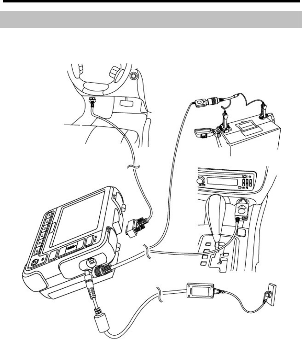
1. Supply external power
There are 4 methods for supplying external DC power to the G-scan.
z With DLC cable
z From the cigarette lighter terminal in cabin
z From the battery of vehicle
z From the AC/DC adapter
2. Power supplying from embedded rechargeable battery (Option)
z When using wireless communication (LF/RF) of TPMS
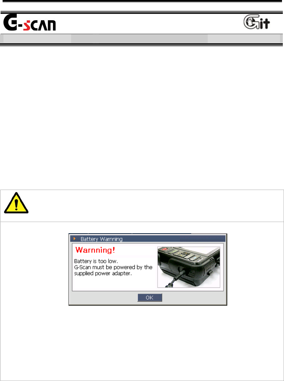
Caution
<Figure 1: Low Voltage Warning for Rechargeable Battery>
z The <Figure 1> is the message warning the low battery. If you see
this message, supply the external power immediately.
z Otherwise, the G-scan will be turn OFF automatically.
User’s Manual
- 24 -
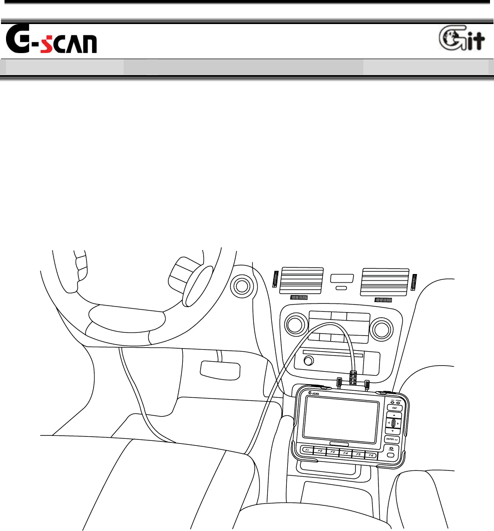
How to connect the external power
<Figure 2: Connect the External DC power to G-scan>
Module NO: A-02-001

User’s Manual
- 25 -
Description of Power Supplying Method
Power supplying with the DLC cable
The vehicle of which diagnosis connector terminal is the 20-Pin
connector or which is satisfying the OBD-II communication regulation
can be supplied the electric power from the DLC cable without any
additional power line.
Note:
The DLC connector, in general, is located at the lower part of the
driver’s front panel. This location may be different somewhat, please
check the correct location before connecting.
From the cigarette lighter in the cabin
Using the cigarette lighter power cable purchased as a basic item with
the G-scan, the electric power can be supplied.
Note:
When using the cigar cable, the power will be cut during ignition of the
engine. Therefore, for the G-scan without rechargeable battery, the
power will be OFF. If your G-scan does not have rechargeable battery
and you diagnose vehicle relating to the ignition of engine, use other
power supplying method.
Module NO: A-02-001
User’s Manual
- 26 -
From the vehicle battery
When power is supplied form the vehicle battery, the electric
power can be supplied without interruption.
Cautions at connecting the vehicle battery
Do not contact the battery power line to the driving part in the
engine room.
Connect correct power lines to the battery terminals.
From the AC/DC adapter
Using the AC/DC adapter purchased as a basic item with the G-
scan, the electric power can be supplied to the G-scan.
When updating the G-scan, use the AC/DC adapter for supplying
stable power to the G-scan.
Warning
Use only the AC/DC adapter supplied by GIT for the G-scan. GIT
has not responsibility for the damage by different kinds of AC/DC
adapter.
Caution
At communicating with vehicle (for all vehicle diagnosis function
with DLC cable), the vehicle battery should be connected always.
For updating the G-scan, connect the AC/DC adapter for supplying
the stable power.
Module NO: A-02-001
User’s Manual
- 27 -
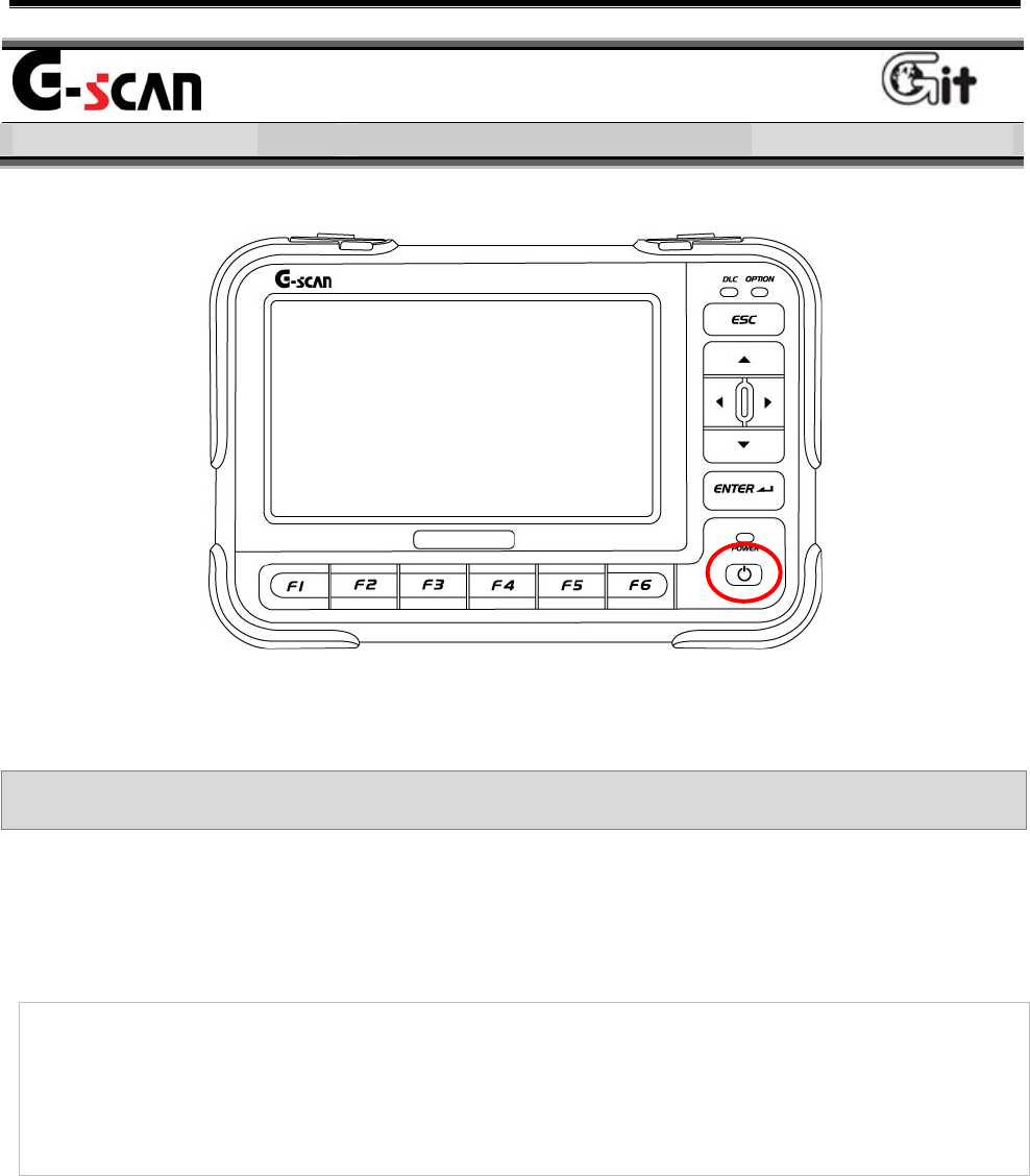
Power ON/OFF
Basic Use of G-scan Module NO: A-02-002
<Figure 1: Location of the Power S/W>
Power ON/OFF Method
Power ON
1) Check the power supplying condition of G-scan.
Notice:
For the details of power connection to the G-scan, refer to “Power
Supplying” of the “Basic use of G-scan”.
2) Press the “Power Switch” shown in <Figure 1> until the DLC LED and
OPTION LED located at upper right of the G-scan are turn from amber
to green. (It requires about 0.5 seconds..)
User’s Manual
- 28 -
Notice
For the lightening color of POWER LED, refer to the “Description for
Main Component of H/W” of the “Basic Use of G-scan” (Module: A-
02-003).
After booting the G-scan normally, the main screen of G-scan will be
shown as <Figure 2>.
<Figure 2: Main Screen of G-scan>
Power OFF
z Press the power switch for 2.5 seconds, the G-scan will be turn off.
Module NO: A-02-002
User’s Manual
- 29 -
Description for Main
Component of H/W
Basic Use of G-scan Module NO: A-02-003
Even the G-scan is developed as its function can be operated through
the touch screen, for more fluent operation of G-scan, please be familiar
with the functions and positions of the buttons, terminals and LEDs
installed at the G-scan hardware.
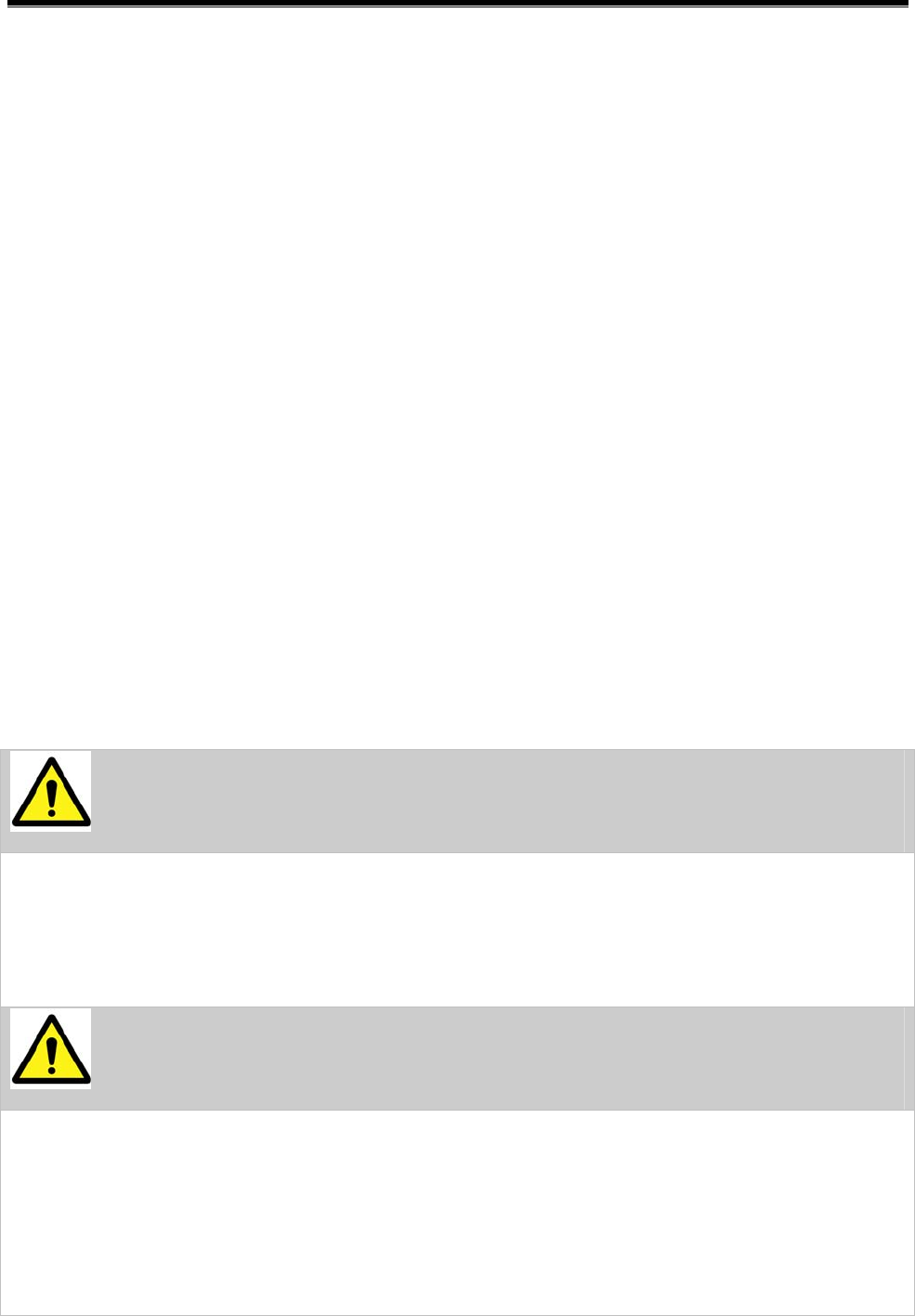
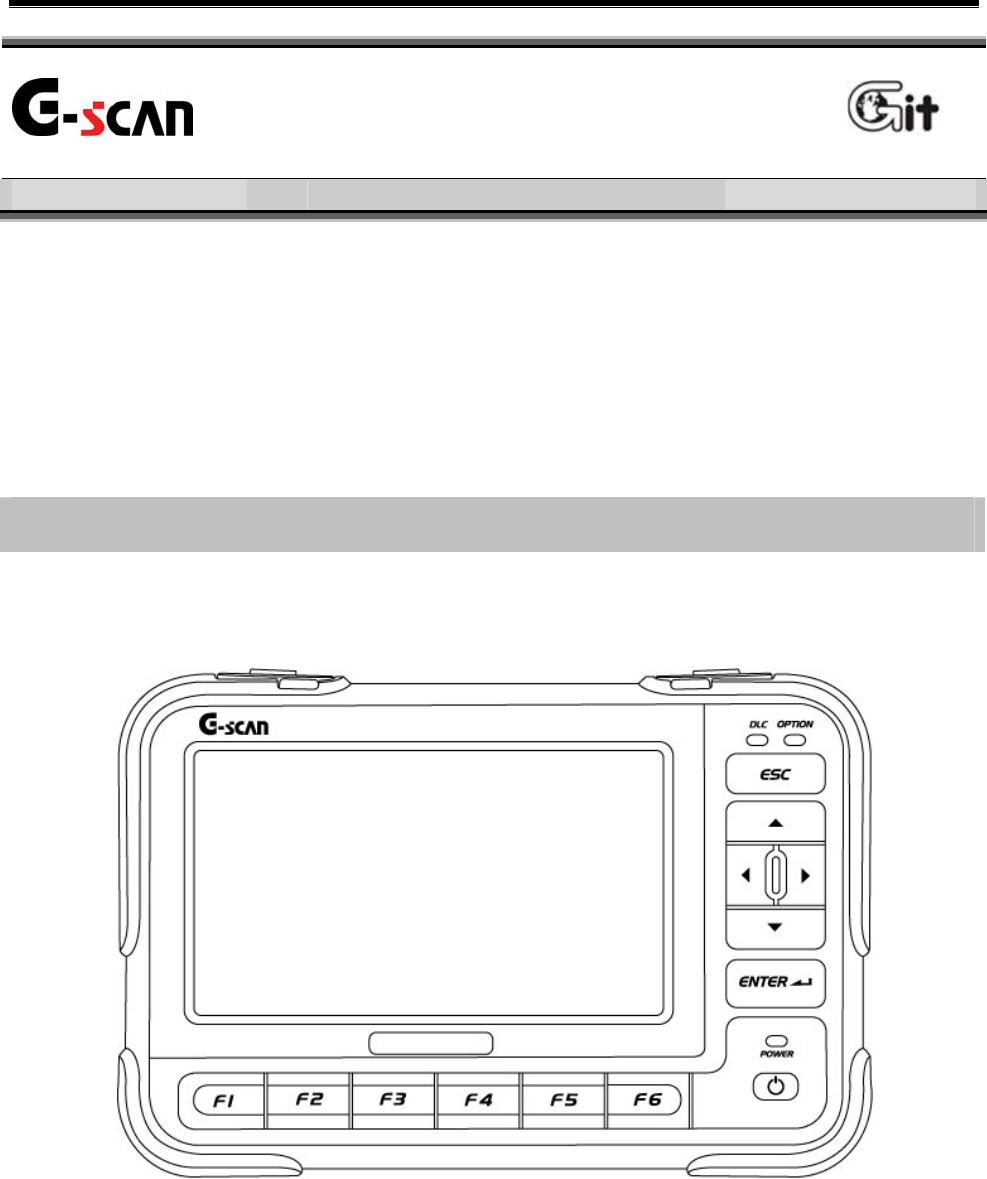
Touch Screen and Input Button
<Figure 1: Front view of G-scan>
User’s Manual
- 30 -
1. Description for Front side of Body
① Touch Screen
Use the specific stylus pen at selecting functions
and items on the touch screen
②
H/W buttons for operating functions represented in the
screen function button at bottom of screen.
③
Exit from the screen currently executed.
Move the previous screen at selecting model.
Close the pop-up window.
④
Execute the item or function selected on the current
screen
Move to the next screen at selecting model.
⑤
Move the cursor to the wanted item or function on the
current screen.
At diagnosing in dual mode, you can select the
diagnosing window with , and the items in
the diagnosing window with , .
⑥ Power ON/OFF the power of G-scan.
⑦ POWER LED LED showing the power condition.
⑧ DLC LED
LED showing the communication condition with the
control module installed in the vehicle.
⑨ OPTION LED
LED showing the communication condition with
supplementary option item connected to G-scan.
Module NO: A-02-003

User’s Manual
- 31 -
Note:
As the CALIBRATION of the touch screen may be changed by the
temperature variation or passing of the time, reset the CALIBRATION of
the touch screen at the “Setup” in the Configuration.
Notice
For the details relating to the power ON/OFF, refer to the “Power
ON/OFF” in the “Basic Use of G-scan” <Module NO: A-02-002>.
z POWER LED Lighting Condition
Charging Charged
With DC power LED (Red) ON LED (Green) ON
Battery Pack
Installation Without DC
power
LED OFF LED OFF
Tips
If the battery pack is not installed, when the external power is connected,
the Power LED lights the Green up.
Notice:
For the details of the power supplying, refer to the “Power Supplying” in
the “Basic Use of G-scan” <Module NO: A-02-001>.
Module NO: A-02-003

User’s Manual
- 32 -
z DLC LED Lighting Condition
LED operating condition
Communicate with Control
Module
LED (Green) Flicker
Communication with Control
module is OFF
LED OFF
z OPTION LED Lighting Condition
TPMS Pack (LF) wireless
transmission
LED (Red) ON
TPMS Pack (RF) wireless reception LED (Green) ON
Communication by USB port (Host)
of the G-scan body
LED (Green) Flicker
Others LED OFF
User’s Manual
- 33 -
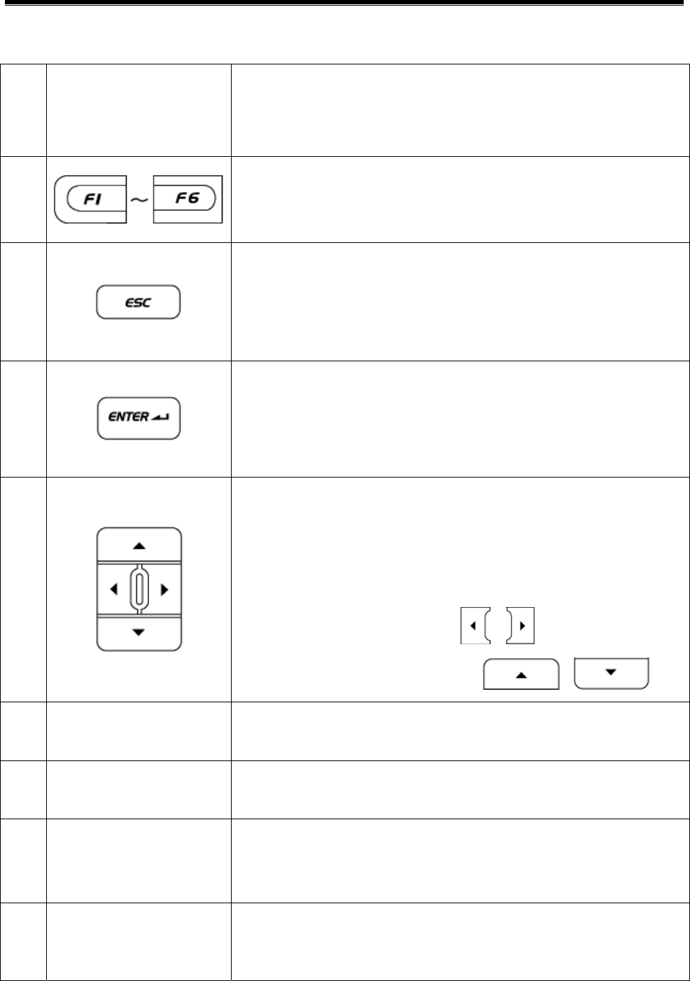
2. Description for the Communication Terminals
<Figure 2: G-scan COM port>
DLC
Terminal for connecting to DLC cable to
communicate with vehicle.
OPTION
The USB Host port prepared for expanding
the function by connecting to additional
equipments in future.
PASS-THRU
The COM port for using the vehicle COM
functions from the PC.
PC COMM
DOWNLOAD
The COM port for maintaining the G-scan and
expanding the functions in future.
User’s Manual
- 34 -
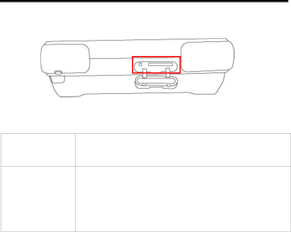
3. SD Memory Slot & Reset Button
<Figure 3 SD Memory Slot and Reset Button>
SD Memory
Slot
Slot for inserting the SD card restoring the various
data for driving the G-scan.
RESET Button
When program has errors by the O/S or other
problems, press the Reset button to turn OFF the
G-scan in force. After pressing the Reset button,
press the Power Switch to reboot the G-scan.
User’s Manual
- 35 -
Description for the Main
Component of the S/W Screen
Basic Use of G-scan Module NO: A-02-004
Unlike the conventional diagnosis equipments, the screen of the G-
scan is equipped with the touch screen. The images output on the G-
scan screen are not simple pictures but the functional buttons for
operating the diagnosis equipment.
This chapter describes the functions and marks commonly applied to
the Main Screen of the G-scan and other diagnosing screen. Please be
familiar with these descriptions to operate G-scan freely.
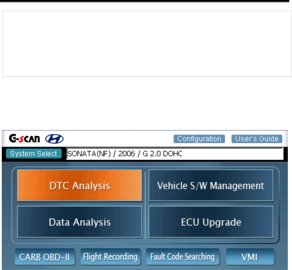
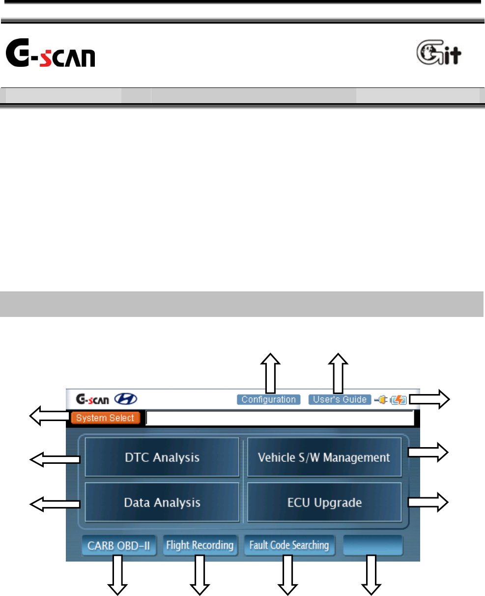
Components of the Initial Screen
<Figure 1: Components of the Main Screen>
③
⑫
⑥
⑦
④
⑤
⑧ ⑨ ⑩ ⑪
① ②
User’s Manual
- 36 -
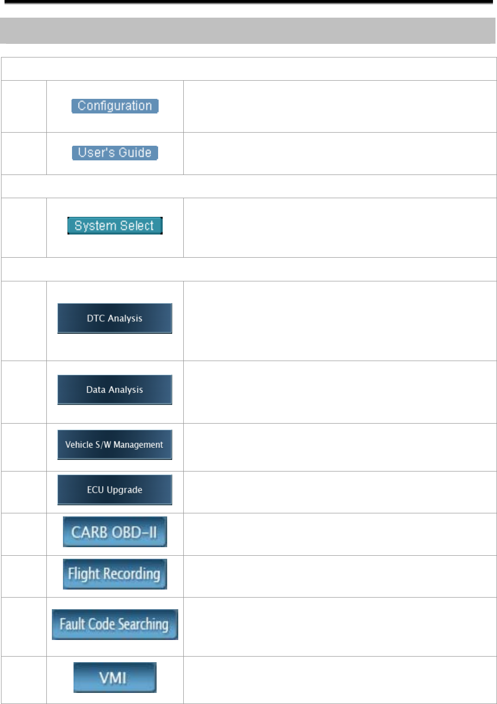
Description for the Components of the Initial Screen
Configuration and Help
①
ConFigure or proceed to the “Setup”, “User
Information”, “Software version” or “Self-diagnosis”
② Support the Help for using this product.
Model Selection
③
Select the model and system for diagnosing.
* The selected system is shown in the window right
side of the “System Select” button.
Diagnosis Menu
④
Show the fault code on the screen by
communication with the selected vehicle system.
Show the additional fault codes by further
communication.
⑤
Check the data of input/output devise of ECU
installed at the current vehicle by the communication
with the selected vehicle system.
⑥
Support supplementary vehicle S/W function except
the diagnosing functions (DTC, Current Data,
Actuation Test).
⑦ Support the ECU upgrade.
⑧
Diagnose the vehicle applied with OBD-II COM
program.
⑨ Recording the travel data, analyze the data.
⑩
Search the fault codes of vehicle systems setup in
system selection multiply at the same time without
re-selection of system.
⑪
At connecting GDS VMI (expanded install item), the
multi-meter, oscilloscope, simulation test functions
are possible.

User’s Manual
- 37 -
Diagnosis Screen Components
<Figure 2: Diagnosis Screen>
Showing the Diagnosing Model and Hot Key
z The diagnosing item currently undergoing and the model for
diagnosing are shown. For the right icons, refer to the following table.
z Description for the Common Icons in Diagnosing Window
Closing the window currently undergoing, return to the initial main
screen.
Capture the screen currently undergoing and save it.
The captured screen will be saved at the “Storage Card₩G-
scanImage₩Model” folder of SD memory inserted into G-scam.
Show the data of the system currently communicating in detail.
Change the system for diagnosing except the vehicle model.
Change to the dual mode from the overall screen.
Change to the overall screen from the dual mode.
User’s Manual
- 38 -
Diagnosing Window
According to the diagnosis mode of the G-scan, it shows the data and
the results of the diagnosis.
<Figure 3: Data Output Window>
Screen Function Button
<Figure 4: Screen Function Button>
At the diagnosis item currently undergoing, the functions of the function
button are shown. the function can be operated by
selecting it using the stylus pen.
Tips:
The property of the screen function button will be changed according to
the diagnosis mode (or the activated window at the dual mode).
User’s Manual
- 39 -
Connecting the DLC cable
Basic Use of G-scan Module NO: A-02-005
For the communication between the control module installed at the
vehicle and the G-scan, the DLC cable should be connected.
According to the kinds of connector used in the communication, there
are different in connection of power supplying line and the adaptor
connection.
<Figure 1: Connecting the DLC cable>

User’s Manual
- 40 -
Vehicle with the OBD-II Standard Connector
Only with the DLC COM cable without additional power line, it is possible
to communicate with control module and to supply power.
Tips
In general, the DLC connector is located at the lower part of the driver’s
front panel. According to the kinds of vehicle, it may be different.
Therefore, before connecting, please check the correct position at first.
Vehicle without the OBD-II Standard Connector
Connecting the power
For the vehicle without the OBD-II standard connector, connect the
power line additionally for operating the G-scan
Connecting the vehicle diagnosis
For the communication with the control module installed at the vehicle,
additional adapter is required. After connecting the adapter to the 16
th
pin of the DLC cable, connect it to the COM connector terminal of the
vehicle.
Notice:
For the power supplying, refer to “Power Supplying”<A-02-001> in the
“Basic Use of G-scan”.
User’s Manual
- 41 -
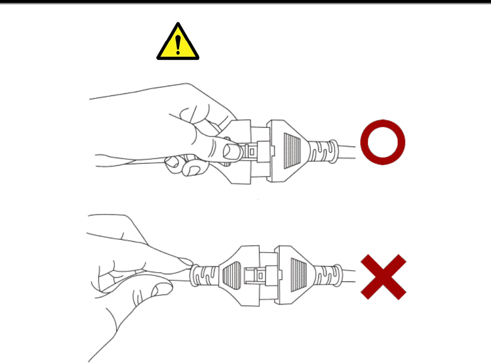
Caution
When disconnecting the main DLC cable, press the locking clip. Do not
pull the wire or distort it. It may cause the damages of the cable or
connector.
User’s Manual
- 42 -
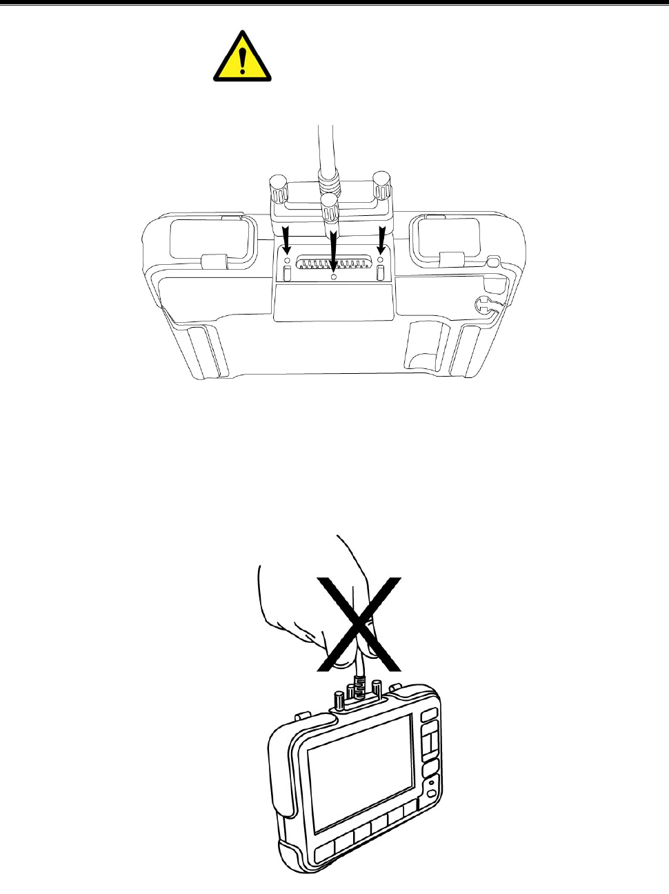
Caution
At connecting the main DLC connector to the G-scan, tighten the 3
clamping screws to the body of G-scan firmly.
At carrying the G-scan, do not hold the DLC cable. Hold the module
body or hand strap.
User’s Manual
- 43 -
Self Test Adapter
Basic Use of G-scan Module NO: A-02-006
The self-test functions are used to check the Main DLC cable (P/No:
G1PDDCA001) and specific related circuits. Not all G-scan circuits are
checked with the self-test functions.
Basic operation of the self-test function is the loop-back theory.
Loop-back theory is verification between sent data from the G-scan
module and returned data, which passed through the pins of all the
outside connectors during the self-test.
Some communication circuits such as high speed CAN, low speed CAN
and SAE-J1708, cannot be checked with loop-back tests.
There are 2 self-test steps included in the Self Test function on the
Configuration menu.
z Step A: Performs test functions by automatically changing circuit
Configurations at the inner end of DLC connector of the G-scan
module.
Purpose and Scope of Self Test (Semi-Test)

User’s Manual
- 44 -
z Step B: Performs test functions on the Main DLC cable using the self-
test adapter which will short all the terminals (except power and
ground functions) at the end of Main DLC cable.
This self-test function cannot determine open or short circuits in other
adapter cables except Cable-DLC (P/No: G1PDDCA001).
User’s Manual
- 45 -
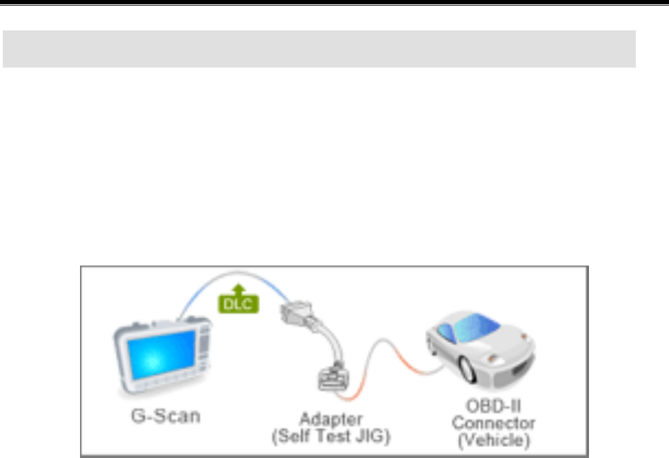
Before performing the self-test function, connect the Main DLC cable
(P/No: G1PDDCA001) between G-scan module and Self-test adapter
(P/No: GHDM – 24D000). Then, connect the other side of Self-test
Adapter to the OBD-∥ Connector on the vehicle as shown in [Figure1].
Figure 1. Installation of the Self-test adapter
After installing the adapter, follow the instructions as indicated on the
Self-Test screen located on the Configuration menu.
Connecting the Self-Test Adapter (GHDM – 24D000)
Module: A
–
01
-
00
3
(p.02)

User’s Manual
- 46 -
Configuration
User’s Manual
- 47 -
Setup
Configuration Module NO: A-03-001
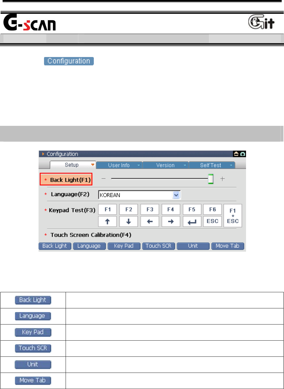
Selecting at the main screen, “Setup” screen will be
shown. In this item, the brightness of touch screen can be adjusted for
the user’s favor, the language can be selected and the operation of key
pad and calibration of the touch screen can be controlled.
Introduction of the Setup Main Screen
<Figure 1: Setup Screen>
The descriptions for the screen function button in “Setup” are as follows.
Item for setup the brightness of LCD screen.
Item for setup the language.
Checking the operations of the 12 function buttons.
Calibrating of the touch screen.
Set the diagnosis Data unit and the Buzzer ON/OFF.
Move to the next Tab.
User’s Manual
- 48 -
Operating Order and References
Screen Brightness Adjustment
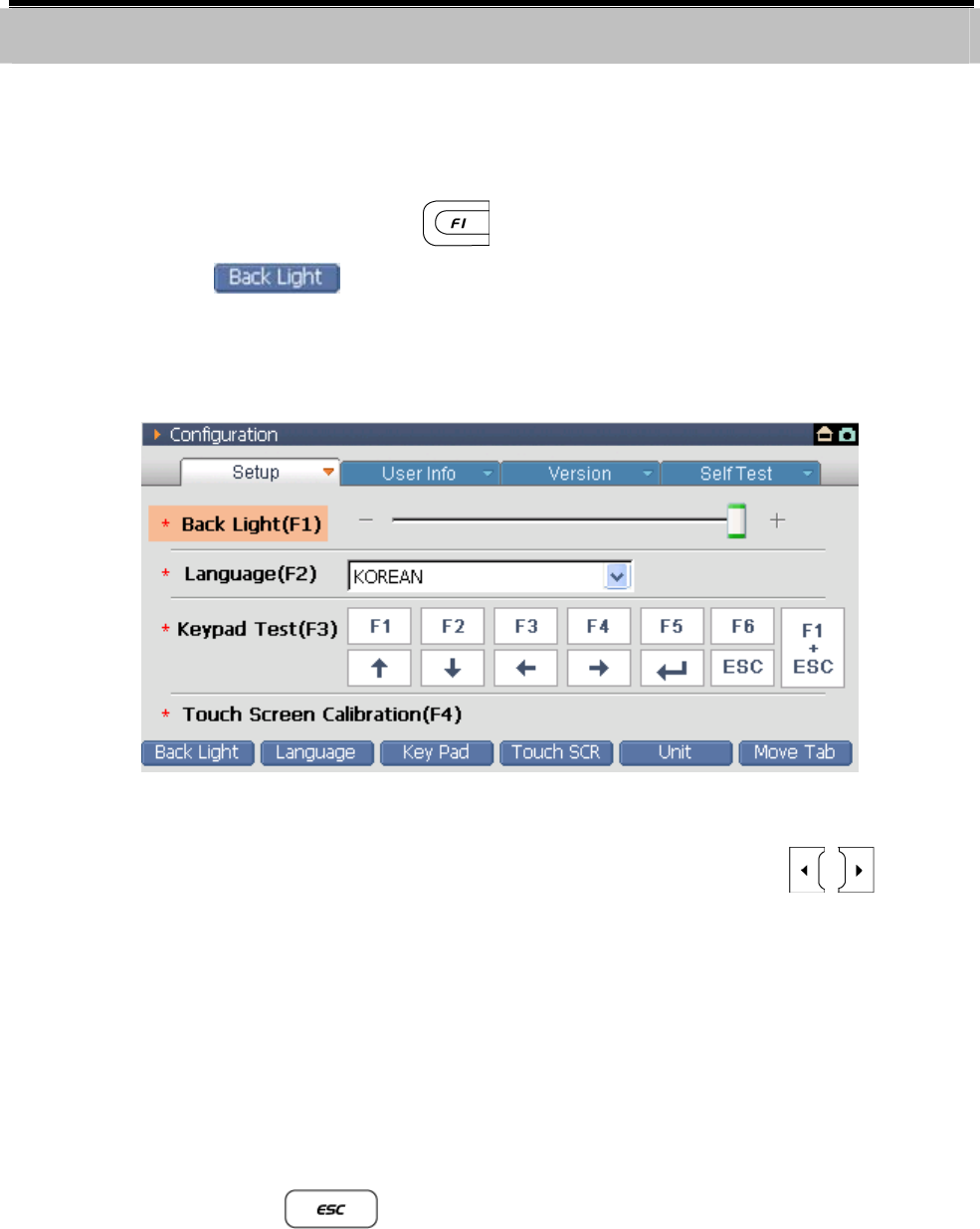
1) Select the “Back Light” item to change the gray scale of ambient color.
Select the function button .
Select the at the bottom of screen on the touch screen.
Select the “Back Light(F1)” on the touch screen.
<Figure 2: Back Light Adjustment>
2) Adjust the brightness using stylus pen or pressing the on the
key pad.
3) It can be adjusted with 5 levels. Screen will be brighter as it is adjusted
to (+).
4) Item movement after adjusting screen
Using stylus pen, move to the item directly on the screen
Selecting the , move to the menu and use the direction
arrow keys to move to wanted item.
User’s Manual
- 49 -
Language Selection
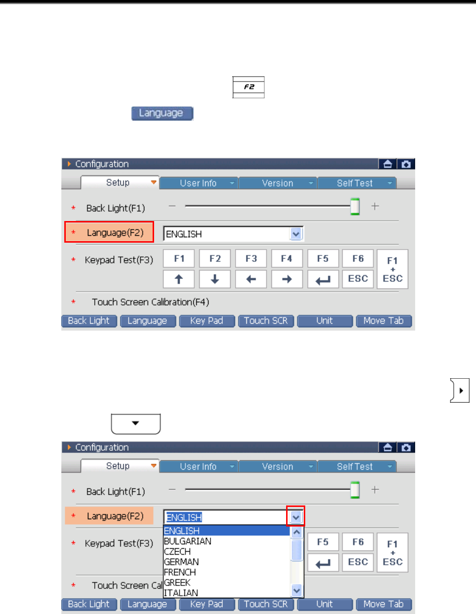
1) Selecting the “Language” item, the gray scale of around is changed.
Select the function button .
Select the at the bottom of the touch screen.
Select the 의 “Language(F2)” on the touch screen.
<Figure 3: Move to Language Selection>
2) Using the stylus pen, press the right mark of language window or ,
and press the . Then language list will be shown.
<Figure 4: Language Selection>

User’s Manual
- 50 -
3) Change item after selecting language
Using stylus pen, select item want to move on the touch screen.
Select or to move to menu, change item using
arrow keys
User’s Manual
- 51 -
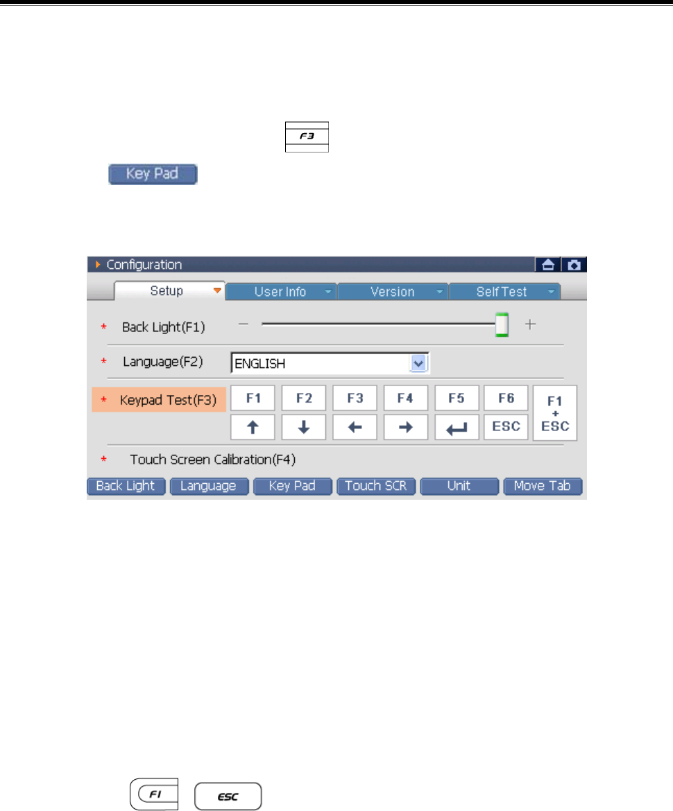
Keypad Test
1) Selecting “Keypad Test” item, around color is changed as shown in
<Figure 5>.
Select the function button .
Select at the bottom of the touch screen.
Select the “Keypad Test(F3)” on the touch screen directly.
<Figure 5: Keypad Test>
2) Pressing the function button F1~F6, arrow keys, ENTER, ESC key, the
color of position representing mark of button will be changed to
orange color. You can easily check the button condition.
3) Change Item after completing Keypad Test
Select item want to move on the touch screen using stylus pen.
Select + at the same time, move to menu. Using
arrow keys, move to the wanted item.
User’s Manual
- 52 -
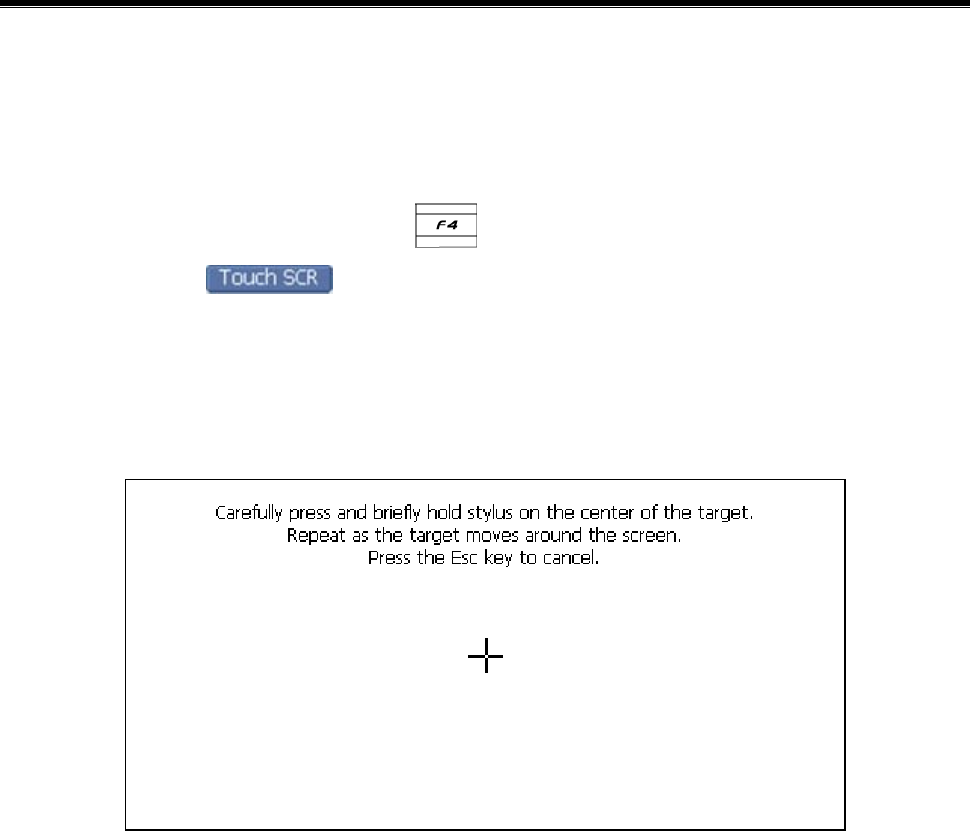
Calibration of Touch Screen
Selecting the “Touch Screen Calibration(F4)” item, following screen will
be shown.
Select the function button .
Select the at the bottom of the touch screen.
Select the “Touch Screen Calibration(F4)” directly on the touch
screen.
<Figure 6: Calibration of Touch Screen>
1) Select the center of (+) mark on the touch screen as shown in the
above figure with the stylus pen.
* Totally 5 points are shown on the screen. Select all center points of the
5 marks.
User’s Manual
- 53 -
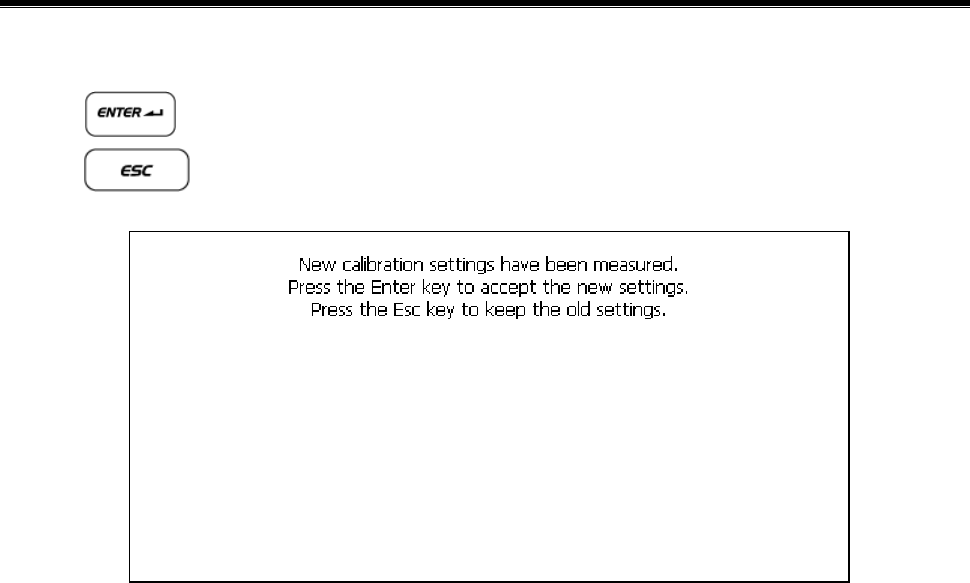
2) After selecting 5 centers of (+) marks, message is shown in <Figure 7>.
: Save the new calibration and move to menu.
: Cancel the new calibration and move to menu.
<Figure 7: Completion of the Touch Screen Calibration >
User’s Manual
- 54 -
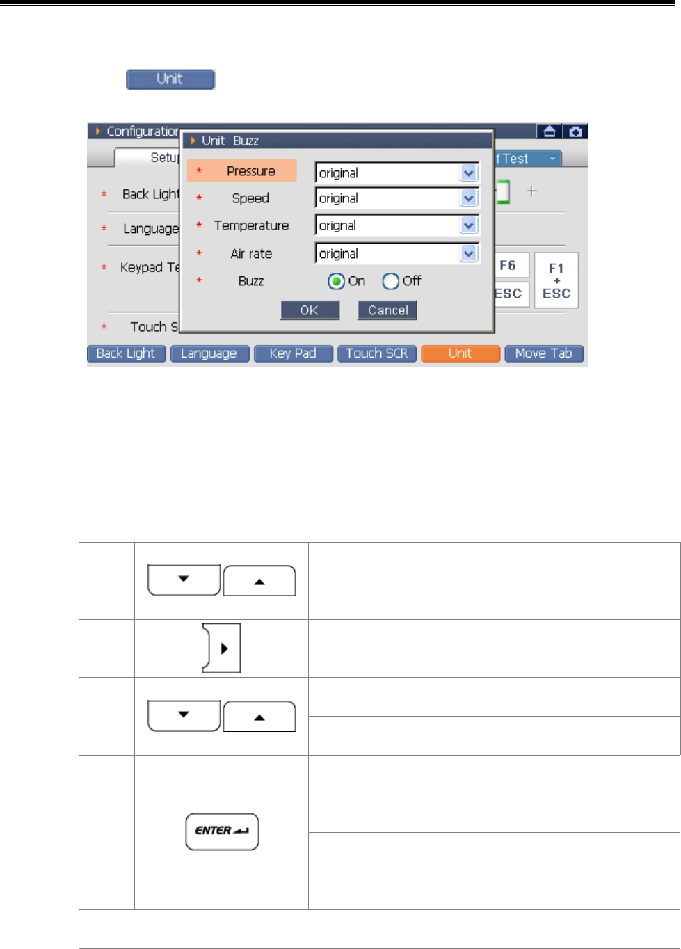
Setup for Unit and Buzzer ON/OFF
1) Selecting or ‘F5’, following setup window will be shown.
<Figure 8: Unit & Buzz setup>
2) Setup the Unit and Buzz operation in the setup window.
Using stylus pen, setup on the touch screen.
Setup using the function button
①
Change to the wanted item among the
setup items
②
Select the item to setup
Unit: select wanted unit in the list.
③
Buzz: select ON or OFF
Unit: after selecting unit, move to
setup list.
④ Buzz: after setup ON/OFF, move to
setup list.
Repeating ①~④, setup the unit

User’s Manual
- 55 -
3) After completing all setup, select at the bottom of setup
window.
Notice:
The unit selected at this Tab is applied to the unit of data represented in
the diagnosis function.
User’s Manual
- 56 -
Exit from“Setup”
After completing “Setup” item, move to other Tab.
Select to move to “User Info”.
Using stylus pen, select the “Tab” on the upper portion of the touch
screen directly to move.
Move to the main screen
Select to move to the main screen.
Select at the right upper portion of the screen to move to the
main screen.
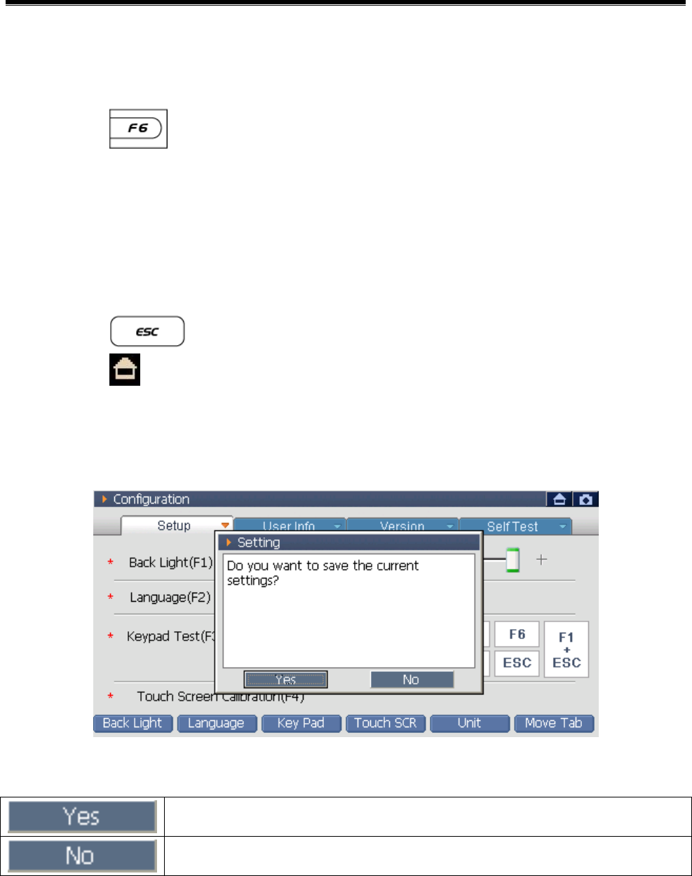
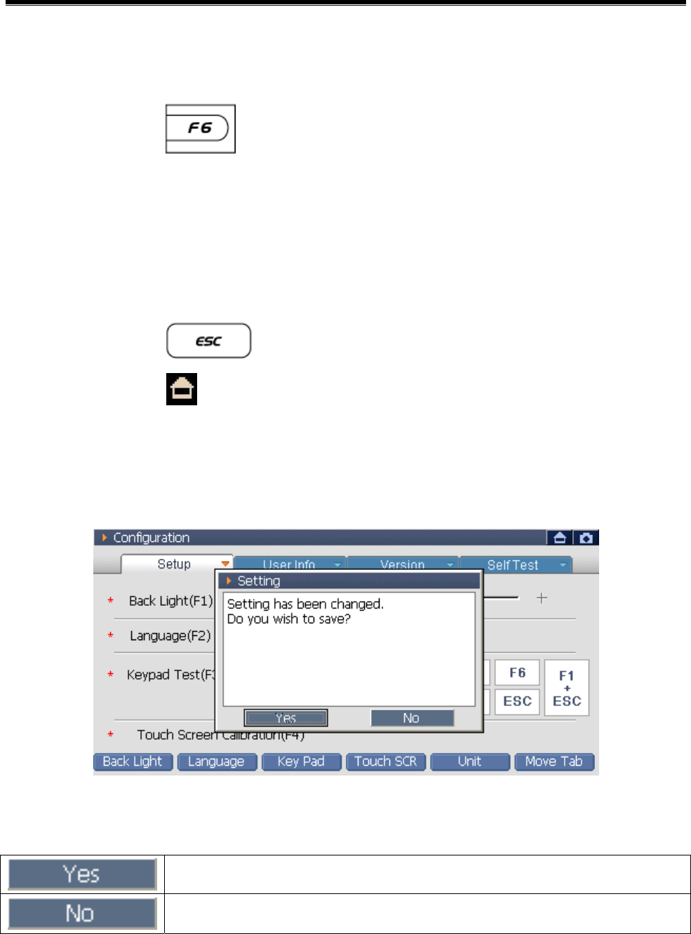
Selecting ‘Move to main screen’, following message will be shown.
<Figure 9: Save Message>
Save the setups and exit to the main screen.
Cancel the setups and exit to the main screen.
“Back Light”, “Touch SCR”, “Unit” among the “Setup” items will be
save with the final setups regardless of this message shown at moving
to main screen.
User’s Manual
- 57 -
User Information
Configuration Module NO: A-03-002
This is the item for inputting customer’s personal information.
To change items in the below level of ‘User Info’ item, use the touch
screen and the function button. To input personal information, us the
touch screen only.
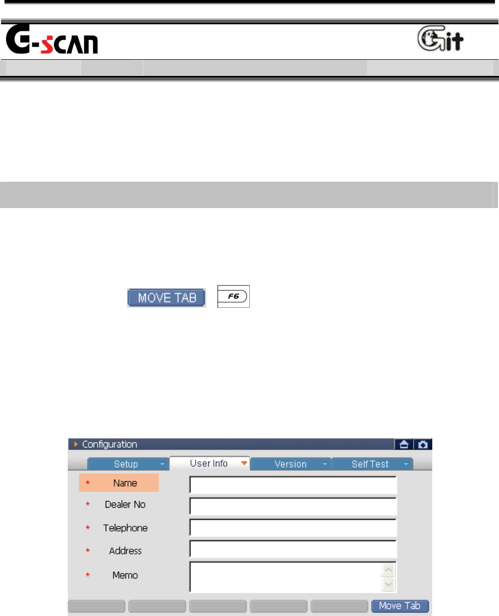
How to input the User Information
How to change to“User Info” item
Selecting the “User Info” on the touch screen using the stylus pen,
following screen will be shown.
Select the , buttons in the “Setup” to move to
“User Info”.
How to change between “User Info” lists
Select the items on the touch screen using the stylus pen.
Using arrow keys (Up, Down) of the function button, move to the
list want to input and press the arrow key (right) to select it.
<Figure 1: User Info Screen>
User’s Manual
- 58 -
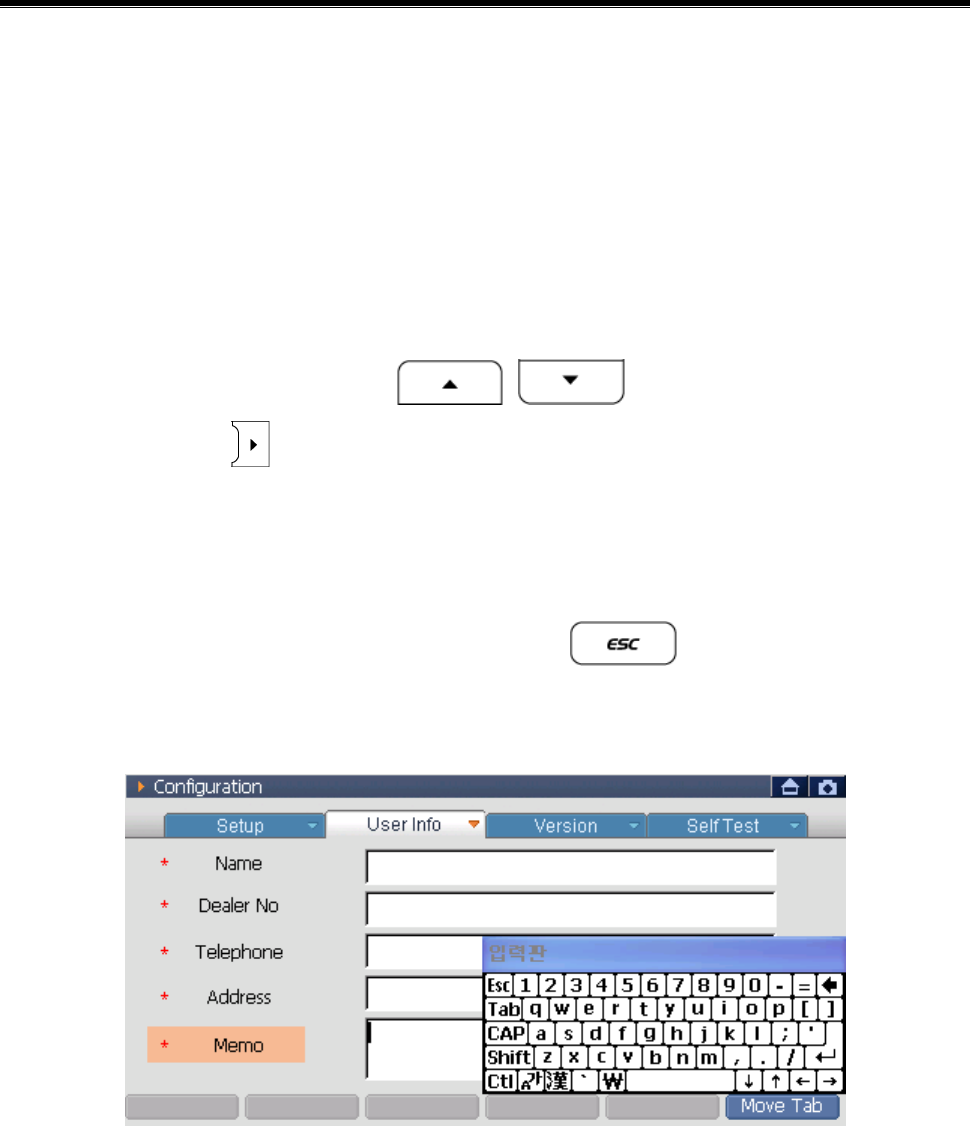
Input the personal information
It is impossible to input the information using the Function &
Supplementary Function buttons. Use the stylus pen on the touch screen
to input personal information.
How to input
1) Using stylus pen, at the “User Info” screen, select the input window or
using the direction button , select the User Info list
and select the , then following keyboard will be shown.
2) Using the stylus pen, press the keyboard on the touch screen to input
the personal information.
3) After input the user information, select or select other input
window using the stylus pen.
<Figure 2: Screen Keyboard>
User’s Manual
- 59 -
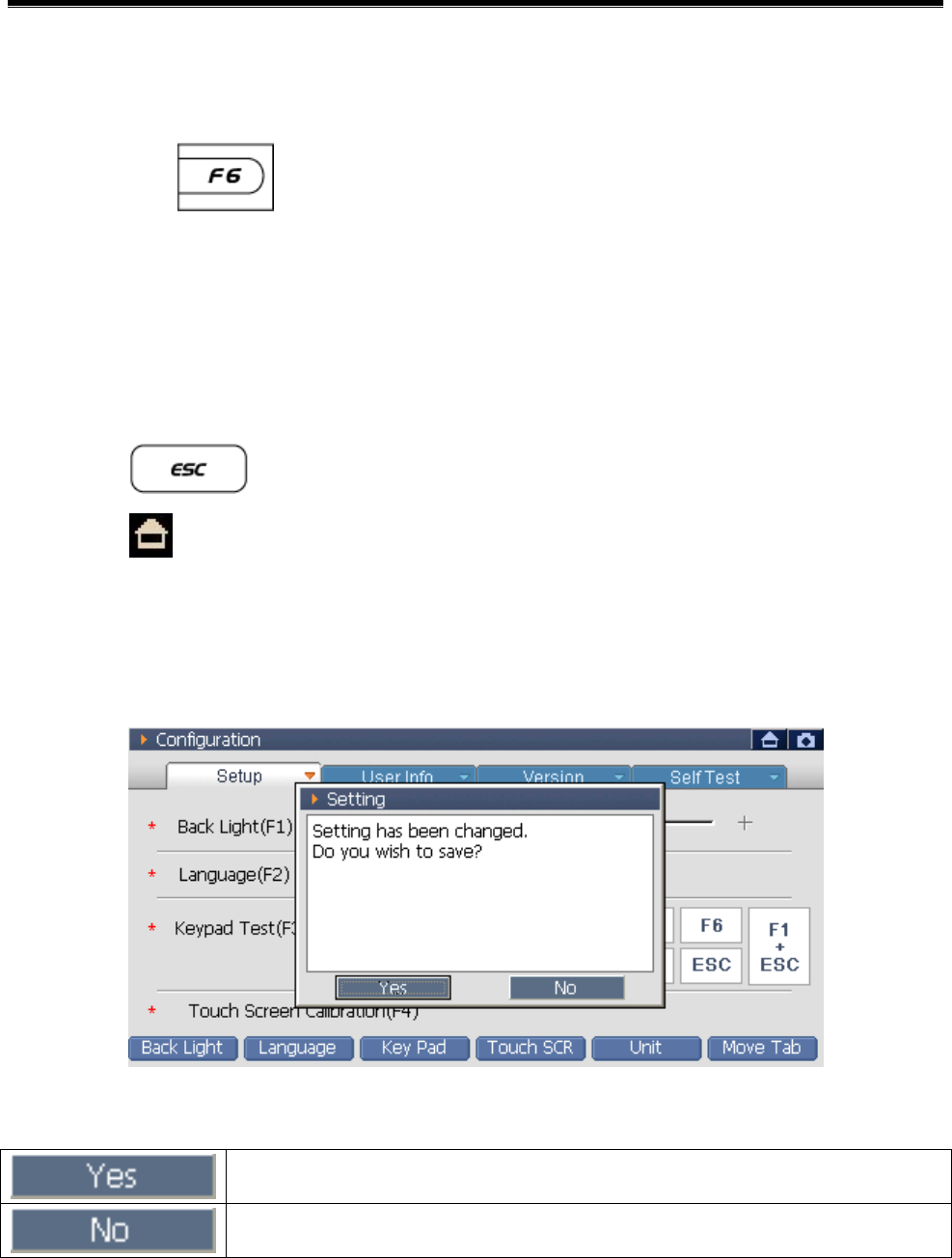
Exit from “User Info”
After setup the “User Info” item, move to other Tab
Select the to move to “Version”.
Select the “Tab” at the upper side of the touch screen using the stylus
pen to move.
Move to main screen
Select to move to the main screen.
Select at the upper right side of the touch screen to move to the
main screen.
Selecting the ‘to main screen’, the following message will be shown.
<Figure 3: Save Message>
Save the setups and move to main screen.
Cancel the setups and move to main screen.
User’s Manual
- 60 -
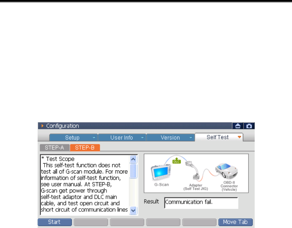
Self Test
Configuration Module NO: A-03-004
It is the function for checking if the circuits relating to the
communication of G-scan and the DLC cable have defects or not. If the
equipment has problems relating to the communication function,
conduct test following to the instruction of the screen.
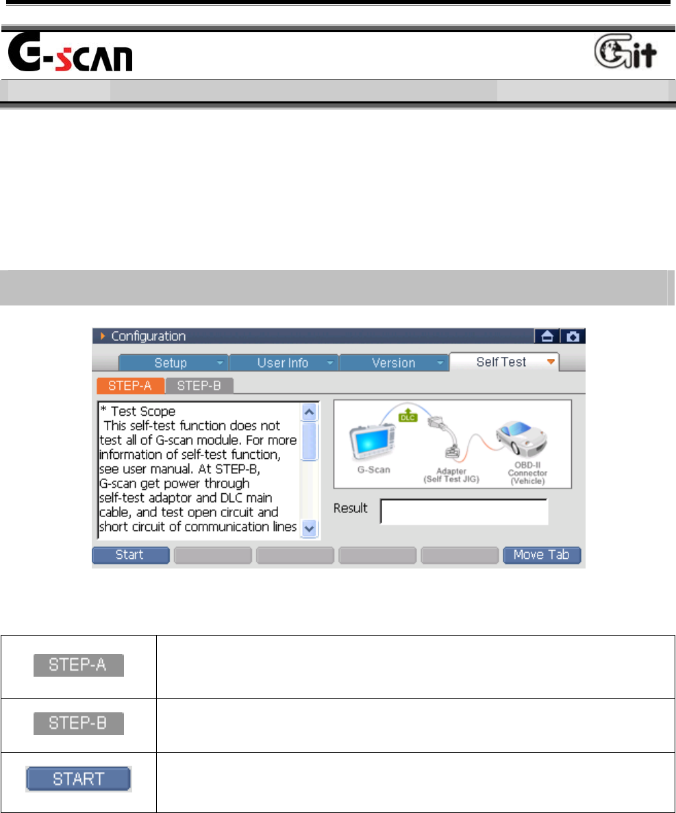
Description of Self Test Screen
<Figure 1: Description of Self Test Screen>
Item for checking the defects of circuits relating to the
communication of G-scan.
Item for checking the defects of the DLC cable.
Start the Self Diagnosis Test.
User’s Manual
- 61 -
Self Diagnosis Test
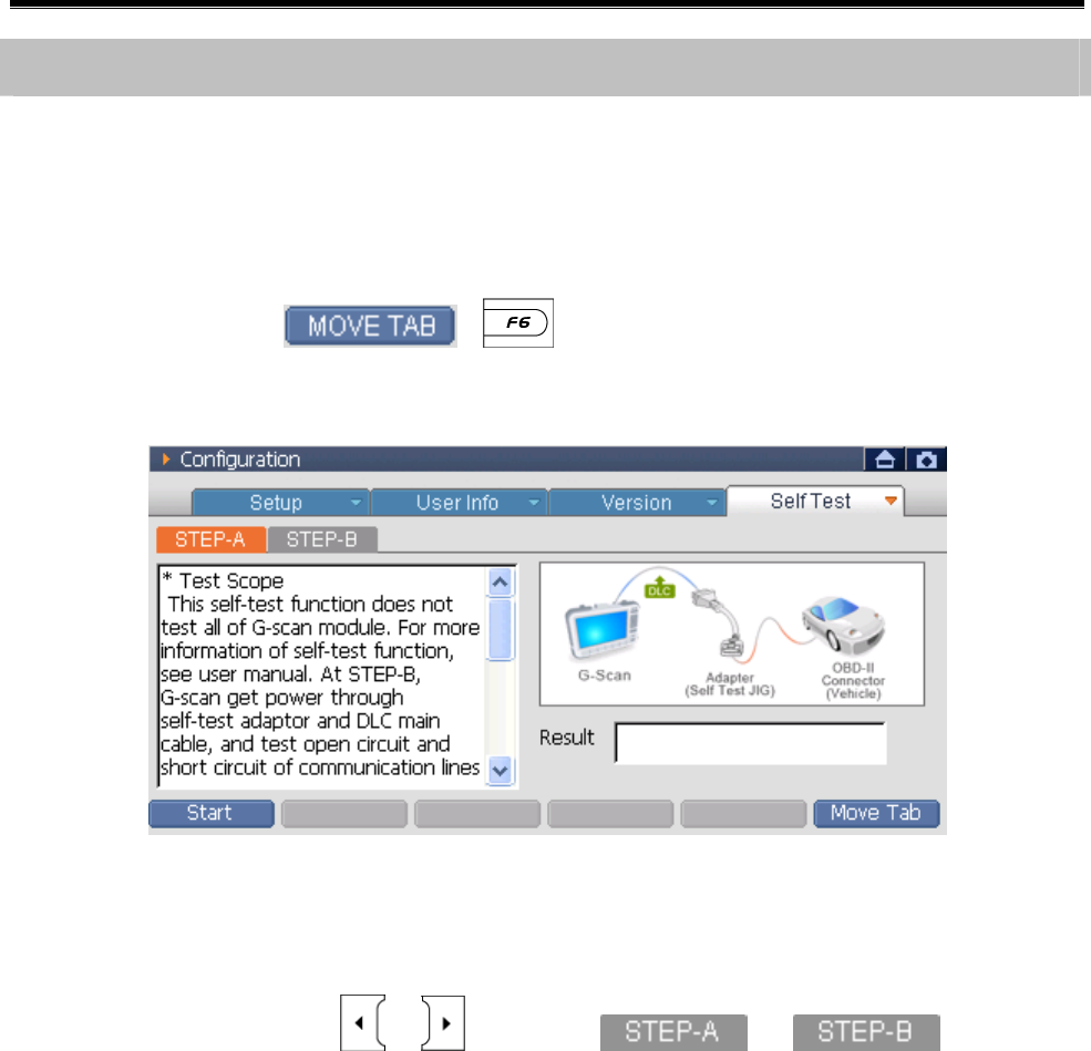
How to change to the “Self Test” item
z Selecting the “Self Test” on the touch screen using the stylus pen, the
following screen will be shown.
z Press the 에서 , button at “Version” to move to the
“Self Test”.
<Figure 2: Move to the Self Test>
z Using the stylus pen, select it on the touch screen or press the
direction buttons , then , can be
selected.
User’s Manual
- 62 -
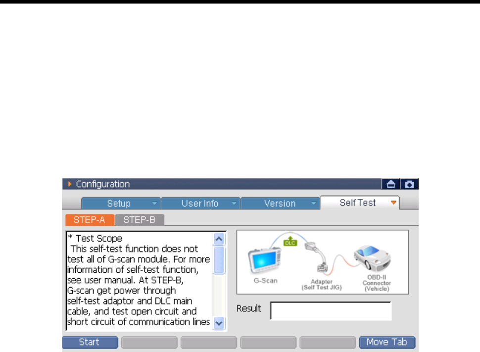
STEP-A Test
The purpose of STEP-A test is for diagnosing the specific
communication circuit of the G-scan. During proceeding with this test,
the power is supplied by the DLC cable and the Self Test adapter. For
the details of Self Test adapter, refer to the ‘Connecting the Self Test
adapter’ in the ‘Basic Use of G-scan’.
<Figure 3: Self Test A Screen>
Method for proceeding with the test is as follows.
1) Connect the DLC cable to the G-scan and connect the Self Test
adapter to the other end of DLC cable. Connect the adapter to the
OBD-II connector of the vehicle.
2) Turn the power of G-scan ON and change to the ‘Self Test’ item of
configuration.
User’s Manual
- 63 -
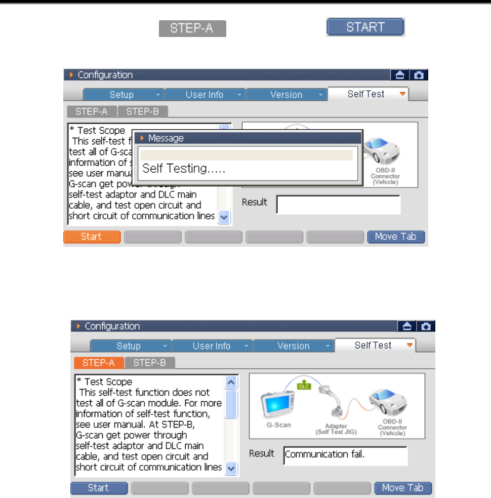
3) After selecting the , select the or ‘F1’ to
proceeding to the test.
<Figure 4: Self Test A Proceeding 1>
4) Check the ‘Test Result’ shown on the test result window.
<Figure 4: Self Test A Result>
Good: Proceed with the test of 16-pin DLC cable; begin the “STEP-
B” test.
Failure: G-scan main module may be inoperative. Contact the
authorized service provider
User’s Manual
- 64 -
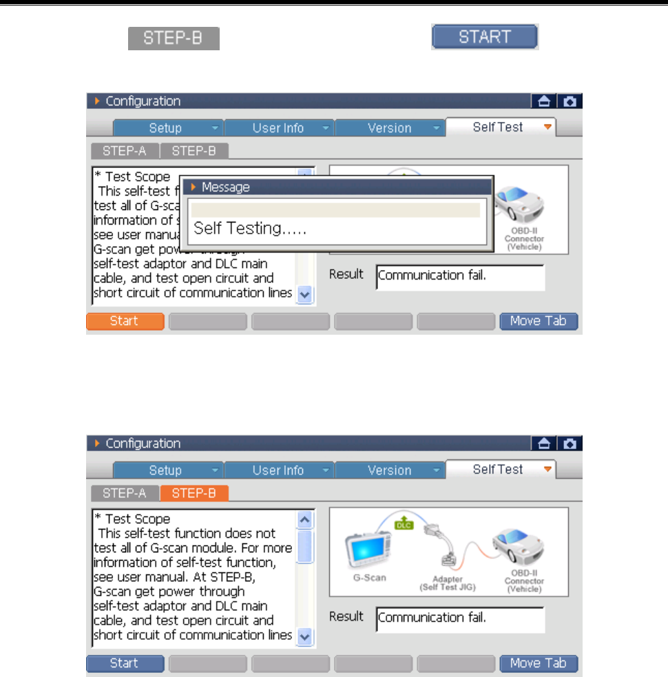
STEP-B Test
The STEP-B test is the function for checking if the DLC main cable
line is broken or shorted with the condition in which the communication
module of G-scan is normal state. During proceeding to this test, the
power is supplied by the DLC cable and the Self Test adapter. For the
details of Self Test adapter, refer to the ‘Connecting Self Test adapter’ in
the ‘Basic Use of G-scan.’
<Figure 5: Self Test B Screen>
The method for proceeding to test is as follows.
1) Connect the DLC cable to the G-scan and connect the other end to
the Self Test adapter. Connect the adapter to the OBD-II connector of
the vehicle.
2) Turn the G-scan power on to move to the ‘Self Test’ item of the
configuration.
User’s Manual
- 65 -
3) Select the and then select the or ‘F1’. The
test will be proceeding.
<Figure 6: Self Test B Proceeding>
4) Check the test result in the test window.
<Figure 7: Self Test B Result>

User’s Manual
- 66 -
The test result messages are explained below:
Good: You may still need to test cable integrity by wiggling to test for
intermittent connections.
** If the test results indicate “Good” and the vehicle communication
continues to fail after the self-test adaptor is removed, verify that the
communication problem is not vehicle related; contact the authorized
service provider if necessary.
Failure: When the test result in self-diagnosis STEP-A are good but the
result of STEP-B is failure, then there is a high possibility that the 16-pin
Main DLC cable (P/No: G1PDDCA001) is inoperative. Contact the
authorized service provider.
Module: A-02-006 (p.10)
User’s Manual
- 67 -
Exit from the “Self Test”
After setup the “Self Test” item, move to other Tab.
z Select the to move to the “Setup”.
z Using stylus pen, select the “Tab” at the upper side of the touch
screen to move there.
Move to main screen
z Select the to move to the main screen.
z Select the at the upper right side of the touch screen to move
to the main screen.
Selecting ‘Move to main screen’, the following message will be shown.
<Figure 8: Save Message>
Save the setups and move to main screen.
Cancel the setups and move to main screen.

User’s Manual
- 68 -
User’s Manual
- 69 -
System Select
Vehicle COM Function Module NO: A-04-001
For diagnosing the vehicle using the G-scan, select the vehicle model
and system wanted to be diagnosed by user at first.
The system selection can select the multiple systems saved in the G-
scan at the same time and diagnose the system problems.
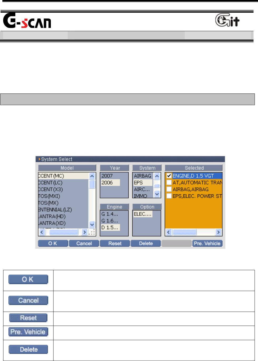
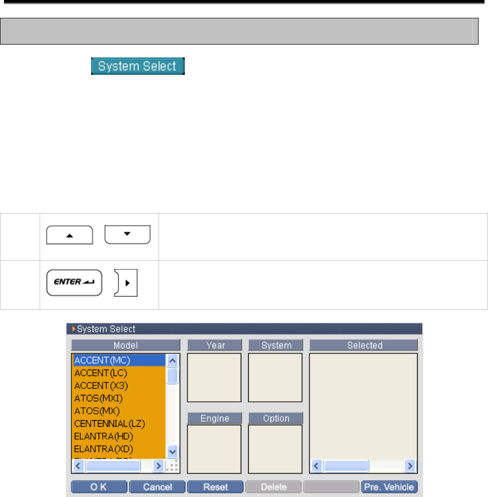
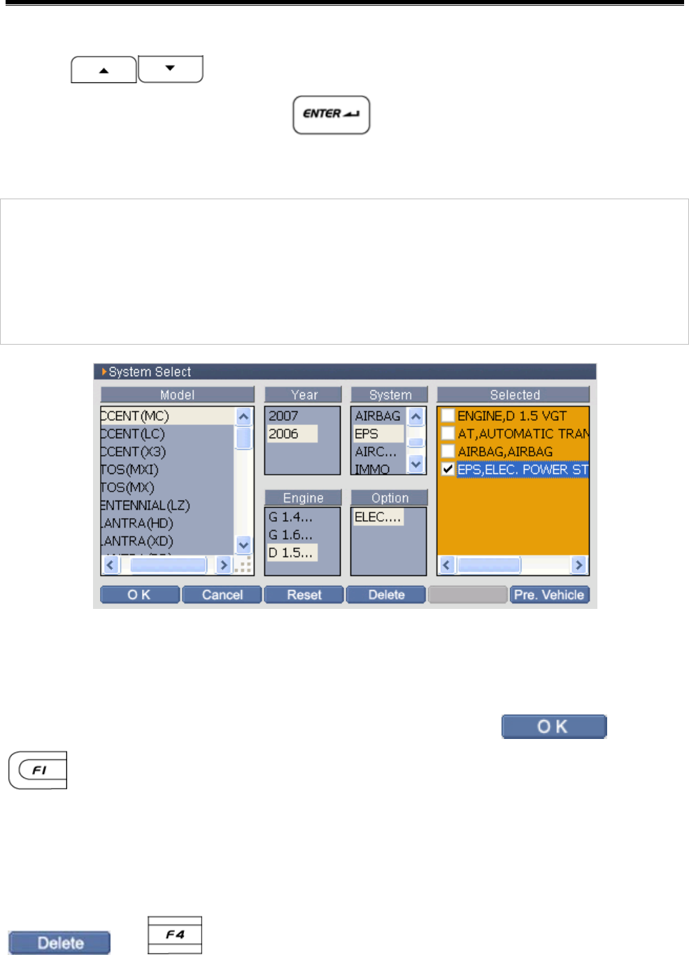
Introduction of Model Selection Screen
For the convenience of user, it is divided into the Model, Year, Engine,
System and Option. According to the order of selected windows, the
system selected by user can be shown in the “Selected” window at right
side.
<Figure 1: Model Selection Screen>
Save the diagnosing system selected by user. Change to the
initial main screen or the diagnosis item screen selected by user.
Cancel the selection of system selection of current window and
return to the main screen.
Release the all system items currently selected.
Set to system SPEC setup in the latest version.
Delete the list on which the cursor is located in the list of the
“Selected” zone.
User’s Manual
- 70 -
System Selection using the H/W Button
Select the on the main screen, then the screen as
shown in below figure will be shown.
How to select System
1) Model Selection
Changing to the system selection screen, the cursor will be located at
the upper portion of the Model Selecting Zone as follows.
<Figure 2: Change to Model Selection Screen>
1 , Set the cursor on the model to be diagnosed.
2 ,
Select the model to be diagnosed. Move to
“Year” zone.
User’s Manual
- 71 -
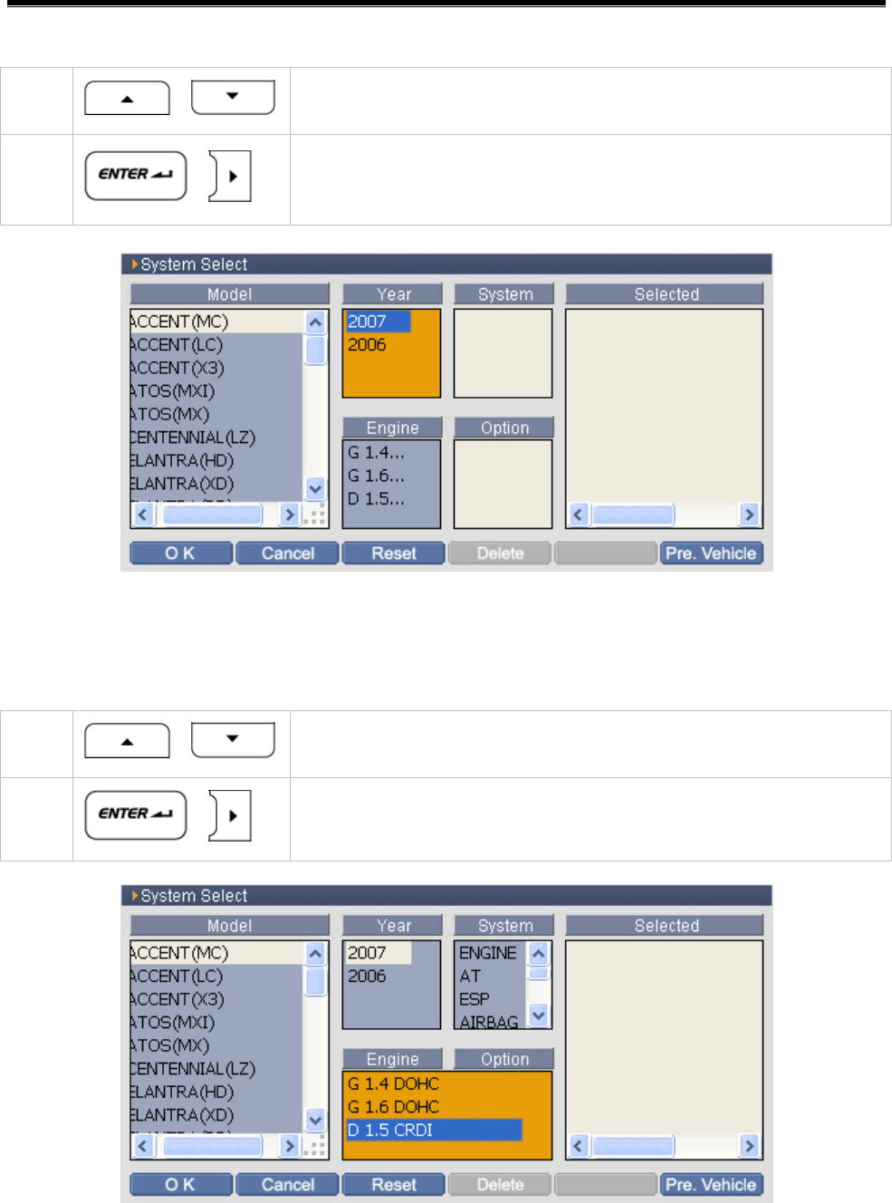
2) Year Selection
<Figure 3: Year Selection>
3) Engine Selection
<Figure 4: Engine Selection>
1 , Set the cursor on the year of model to be
diagnosed.
2 ,
Select the year of model to be diagnosed. Move
to “Engine” zone.
1 , Set the cursor on the engine of model to be
diagnosed.
2 ,
Select the engine of model to be diagnosed.
Move to “System” zone.
User’s Manual
- 72 -
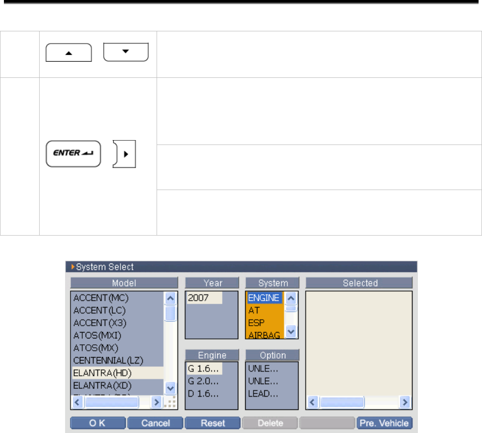
4) System Selection
<Figure 5: System Selection>
1 , Set the cursor on the system of model to be
diagnosed.
After selecting the system of model to be
diagnosed, conduct followings according to the
condition.
When there is one system option:
The system is registered in the “Selected” zone.
2 ,
When there are two or more system options:
Move to the “Option” zone.
User’s Manual
- 73 -
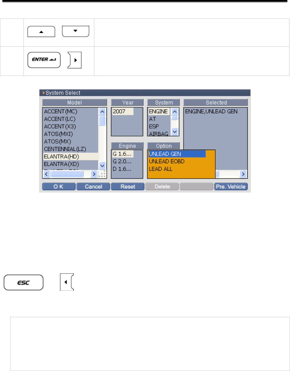
5) Option Selection
<Figure 6: Option Selection>
6) Multiple System Selection
When the number of the System to be diagnosed is multiple, press the
or with cursor locating at “Selected” zone to move to
the “System” zone and repeat from 4) to select again.
Notice:
During selecting system, when it moves to upper zone than “System”
zone (“Model”, “Year”, “Engine” zones), all previously selected
system selection will be released.
1 , Set the cursor on the system option of model to
be diagnosed.
2 ,
The system option of model to be diagnosed is
registered in the “Selected” zone.
User’s Manual
- 74 -
7) Main Diagnosis System Selection
Using in the “Selected” zone, locate the cursor on the
wanted system and select the . Then the ; mark will be
shown at the front of the system name as following figure.
Main Diagnosis System:
The vehicle communication function except the “Fault Code Searching”
can communicate with the control module marked with ; at vehicle
selection. Please be advised that the other control modules without ;
mark can communicate in the “Fault Code Searching”.
<Figure 7: Main Diagnosis System Selection>
8) Completion of System Selection
After selecting all system to be diagnosed, press the or
button to complete the system selection.
9) Delete the selected System
For deleting the system registered in the “Selected” zone, select the
system to be deleted in the “Selected” zone and then press the
or button.
User’s Manual
- 75 -
System Selection using touch screen
z The system selection order and cautions using the touch screen are
the same with them using the H/W button described above. Using the
stylus pen, select wanted items on the touch screen.
z When the wanted items are not shown in each zone, move the scroll
bar up and down to find the items.
z To delete the registered system in the “Selected” zone, select the
system in the “Selected” zone again and then press the
or button.
Note:
The system selection setup finally by user is not deleted even the
power is OFF. When the is selected, the previous setup
will be applied again.
.
Multiple System Selection
The multiple of control modules registered in the “Selected” will shows
all fault codes saved in the control modules to be diagnosed in one
screen by just one function selection using the .
Select all control modules which may have problems in the vehicle.
However, it is not supported to the vehicle applied with special protocol
type communication method.
User’s Manual
- 76 -
Fault Code Searching
Vehicle COM Function Module NO: A-04-002
It, the error diagnose mode, can search the all fault codes occurred at
the multiple system selected at the ‘System Selection’, diagnose the
problems at the system having fault code and move to the ‘Service Data’
directly.
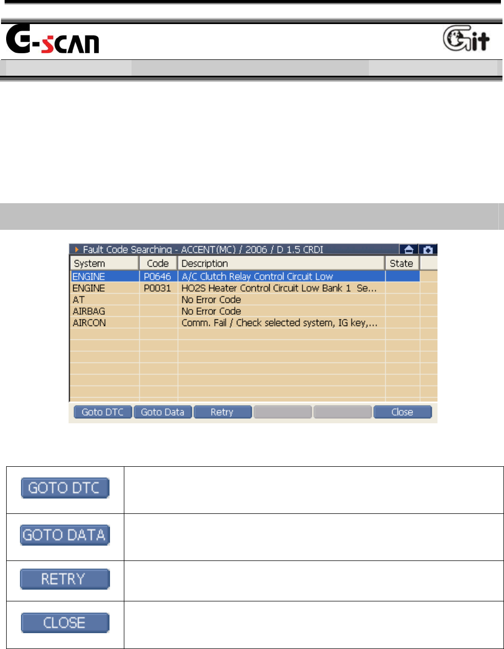
Introduction for Fault Code Auto Searching Screen
<Figure 1: Fault Code Search Screen>
Change to the Error Diagnosis Mode of system
selected at the “Fault Code Search” window.
Change to the Service Data Mode of system selected
at the “Fault Code Search” window.
Search the fault code of the selected system again.
Close the current window and change to the main
screen.
User’s Manual
- 77 -
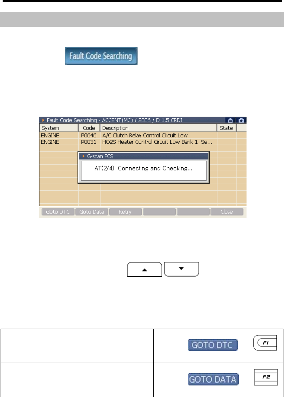
Operating Sequence and Reference
Fault Code Searching
Executing the in the main screen after completing
system selection, the fault code occurred at all system selected at the
system selection are searched and shown on the screen as the
following figure.
<Figure 2: Fault Code Search>
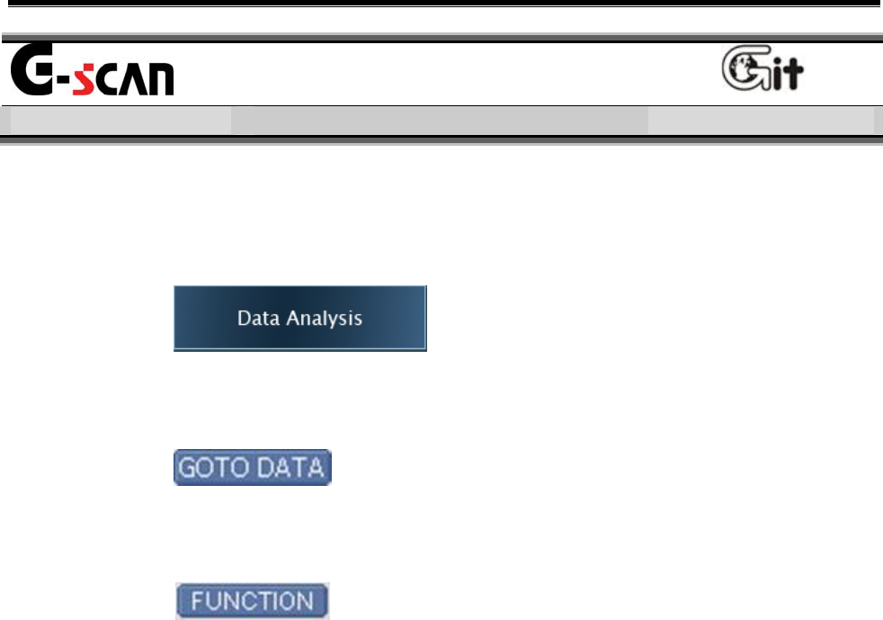
DTC Analysis, Current Data Analysis
1) Using the stylus pen or buttons, select the
searched fault code item.
2) Select the diagnosis mode.
Move to DTC Analysis of system
having fault code selected at step 1). Select or
Move to Data Analysis of system
having fault code selected at step 1). Select or
User’s Manual
- 78 -
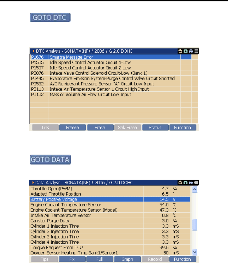
z When is selected
You can delete the fault code and check the data for the related DTC.
<Figure 3: When ‘GOTO DTC’ is selected>
z When is selected
You can check the input/output status of related control module.
<Figure 4: When ‘GOTO DATA’ is selected>
User’s Manual
- 79 -
DTC Analysis
Vehicle COM Function Module NO: A-04-003
The "Fault Code Searching" searches the fault code of the system
selected by user and presents exact information of the fault code and
can delete the fault code after troubleshooting the faults.
There are 3 methods for using the fault code searching.
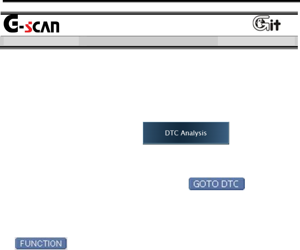
z On the main screen, select the .
→ Move to the DTC Analysis of main diagnosis system set at the
system selection.
z On the “Fault Code Searching”, select the .
→ Move to the DTC Analysis of the control module in which DTC
selected at the “Fault Code Searching” is include.
z Select the DTC among the menu output after selecting the
at the “Data Analysis”
→ The “DTC Analysis” and “Data Analysis” of the control module
which communicated at the “Data Analysis” are output at the same
time in dual mode.
User’s Manual
- 80 -
Introduction of Fault Code Searching Screen
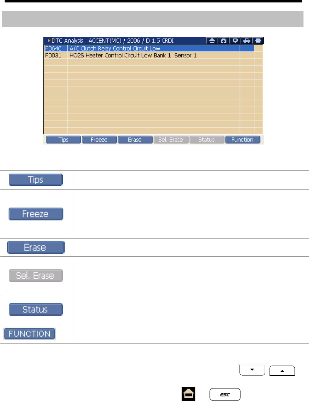
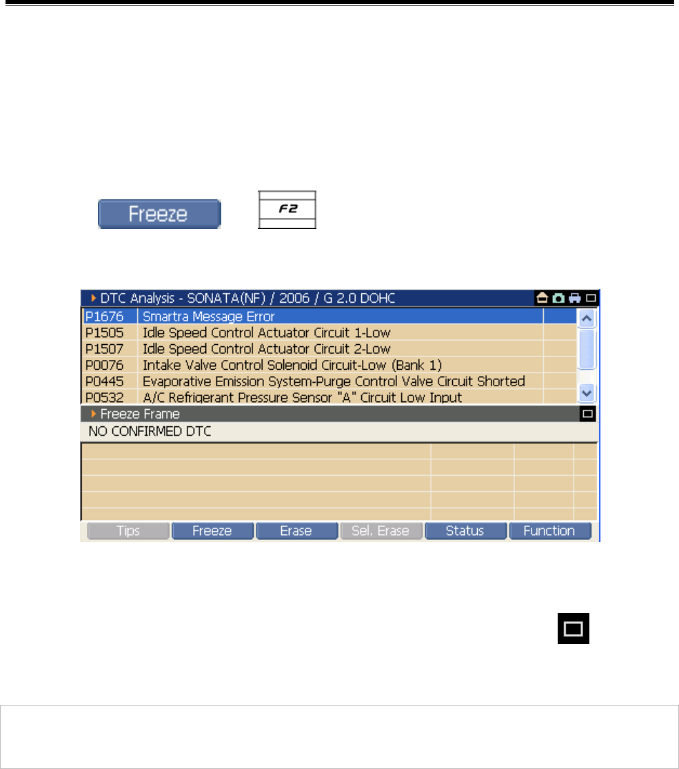
<Figure 1: DTC Analysis Screen>
General Description of fault code are shown.
As the Freeze Frame function, the input/output data of the control
module relating to the saved fault code when the fault code is
occurred.
* According to the specification of control module, function
supporting is different.
Delete all fault codes saved at the control module
Delete the fault code selectively among the fault codes shown by
the fault searching.
* According to the specification of control module, function
supporting is different.
Show the “Fault Detail Information”.
* According to the specification of control module, function
supporting is different.
Change to the dual mode and use other supplementary
information function.
Note:
z When all items are not shown in one screen due to a lot of fault codes, move the
scroll bar at right side using the stylus pen or the arrow keys to
find item you want.
z If you want to back to main screen, press the or at the right upper
side in <Figure 1>.
User’s Manual
- 81 -
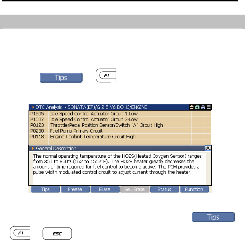
See Tips
1) To see the detail information about the fault code occurred by the
diagnosis result, select the relating fault code item.
2) Select the or buttons, a description window will
be shown as in <Figure 2>.
<Figure 2: Show Tips>
3) If you want to close the ‘General Description’ select the ,
or .
Fault Searching Sequence and Reference
User’s Manual
- 82 -
See Freeze Frame
1) Select the fault code item of the Freeze Frame you want to see.
Freeze Frame: Data of sensor related to the fault code saved by the
control module when fault code is occurred.
2) Select or button on the fault searching screen,
you can see the Freeze Frame as shown in <Figure 3>.
<Figure 3: See the Freeze Frame>
3) If you want to close the Freeze Frame screen, select the of “DTC
Analysis” at the upper side of <Figure 2>.
Notice:
According to the control module, it is supported to some kinds of model.
User’s Manual
- 83 -
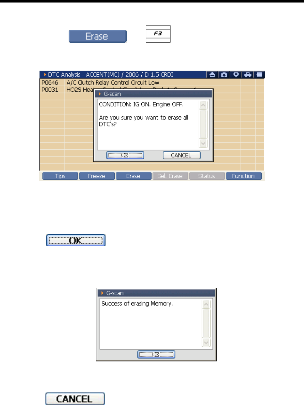
Delete the Fault Code
1) Select the or button on the fault searching
screen.
<Figure 4: Delete Fault Code>
2) As shown in <Figure 4>, the message window for deleting the fault
code is shown overlapping the diagnosis window.
- When is selected:
All fault codes are deleted and the message like the <Figure 5> will
be shown.
<Figure 5: Fault Code Delete Message>
- When is selected:
The Fault Code delete will be canceled.
User’s Manual
- 84 -
Fault Code Selection Delete
1) Select the fault code to be deleted on the Fault Searching Screen.
2) Select the or button.
3) The message for checking the fault code delete will be shown.
- When is selected:
The fault code selected in step 1) is deleted and message is shown.
- When is selected:
The fault code delete is cancelled.
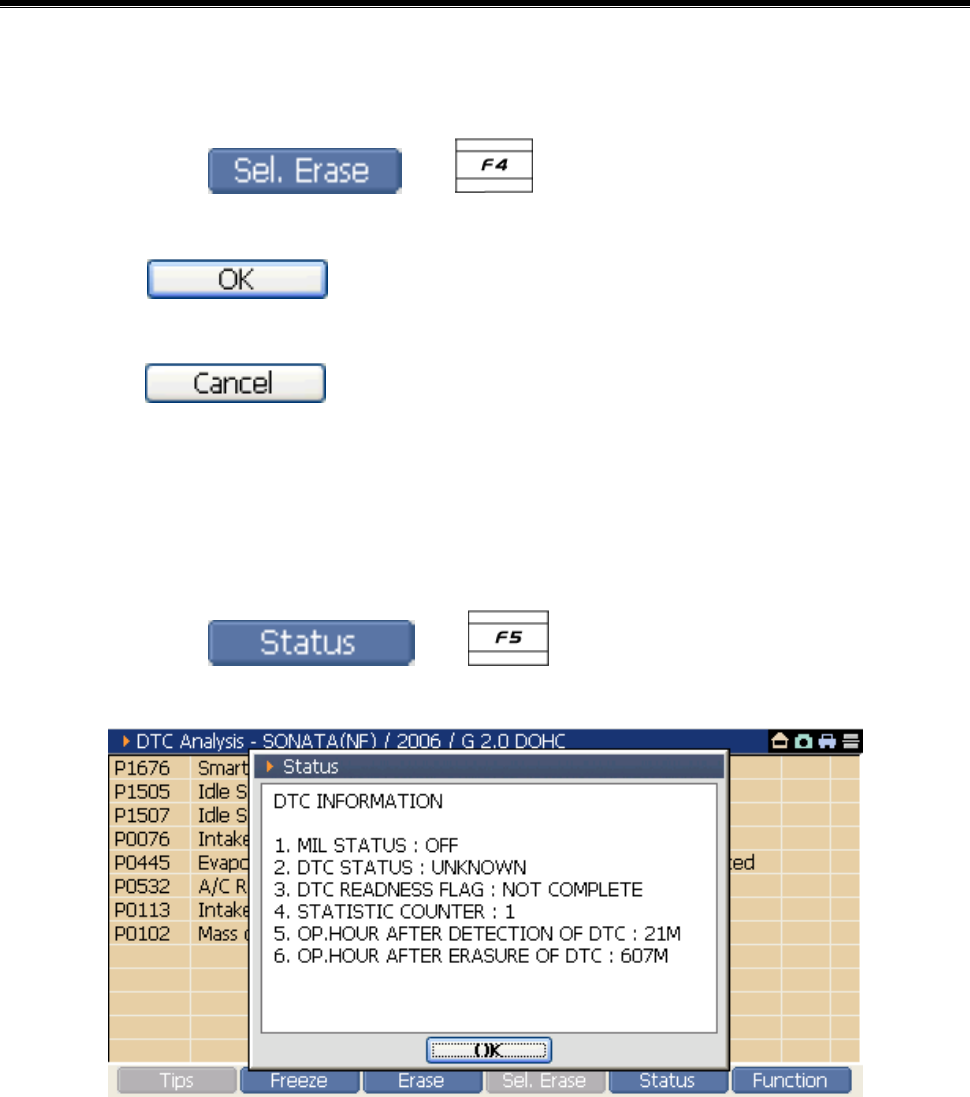
See the Fault Code Detail Information
1) Select the fault code on the Fault Code Searching screen.
2) Select the or button.
<Figure 5: Detail Fault Information>
3) As shown in <Figure 5>, the “Fault Code Detail Information” window
will be shown. You can check the detail information about the
selected fault code.
User’s Manual
- 85 -
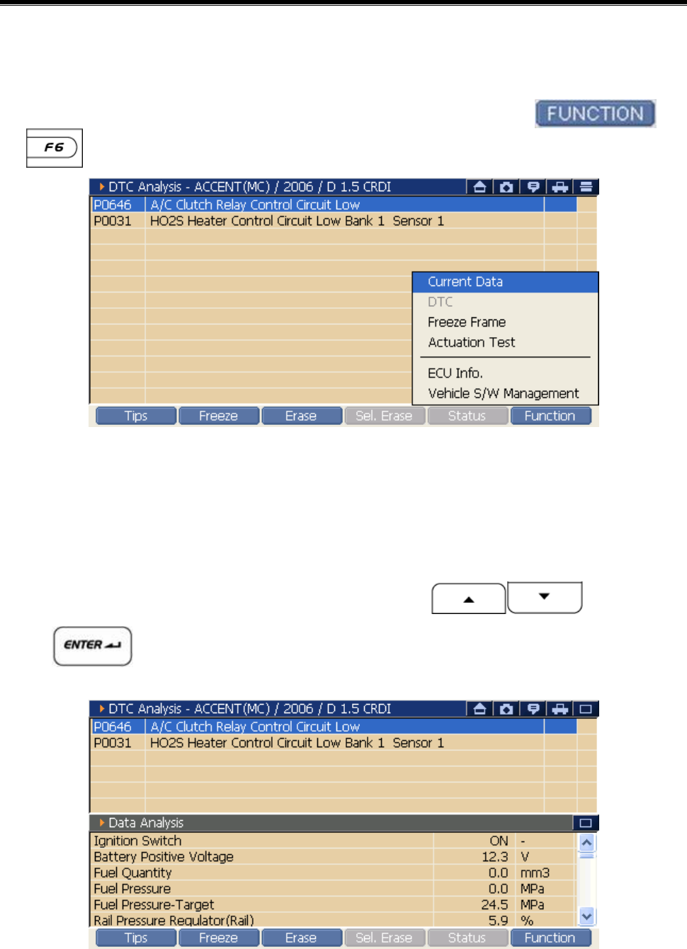
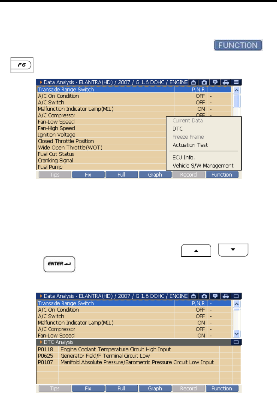
DTC Analysis Dual Diagnosis Mode
See the DTC Analysis and Data Analysis at the same time
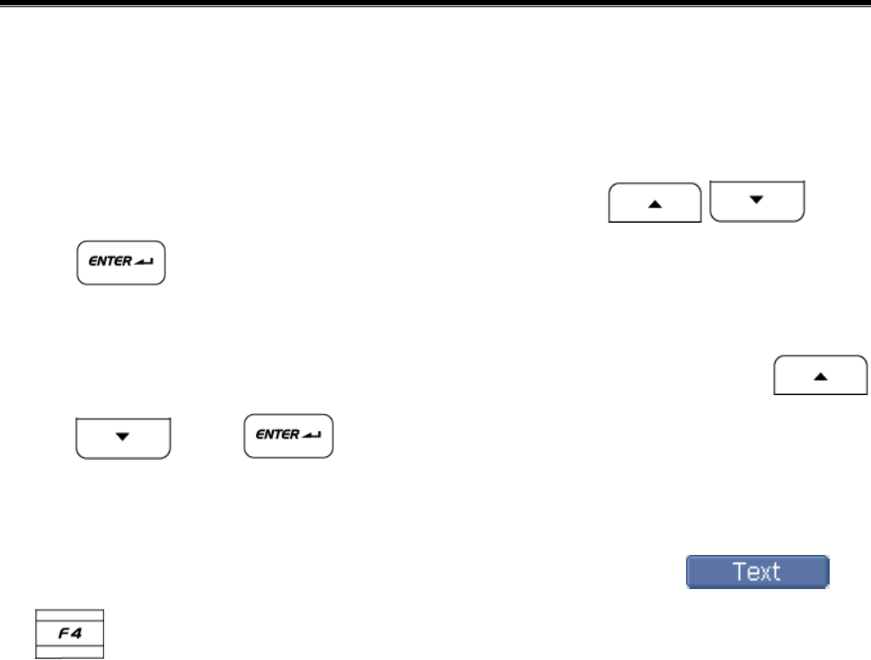
1) On the <Figure 1> DTC Analysis screen, select the or
, the Function Menu is shown as in <Figure 6>.
<Figure 6: DTC Analysis “Function Menu”>
2) On the showing menu, select the Current Data, it changes to the Dual
mode as shown in <Figure 7>.
Using stylus pen, select on the touch screen directly.
After moving cursor using H/W buttons , press the
button
<Figure 7: DTC Analysis & Data Analysis Dual Diagnosis Mode>
User’s Manual
- 86 -
See DTC Analysis and Actuation Test at the same time
1) On the <Figure 1> DTC Analysis screen, select or ,
The Function Menu will be shown as in <Figure 6>.
2) Select the Current Data on the showing menu, then it changes to the
Dual mode as shown in <Figure 8>.
Select it using stylus pen on the touch screen.
After moving the cursor using H/W buttons , press
the button.
<Figure 8: DTC Analysis & Actuation Test Dual Diagnosis Mode>
User’s Manual
- 87 -
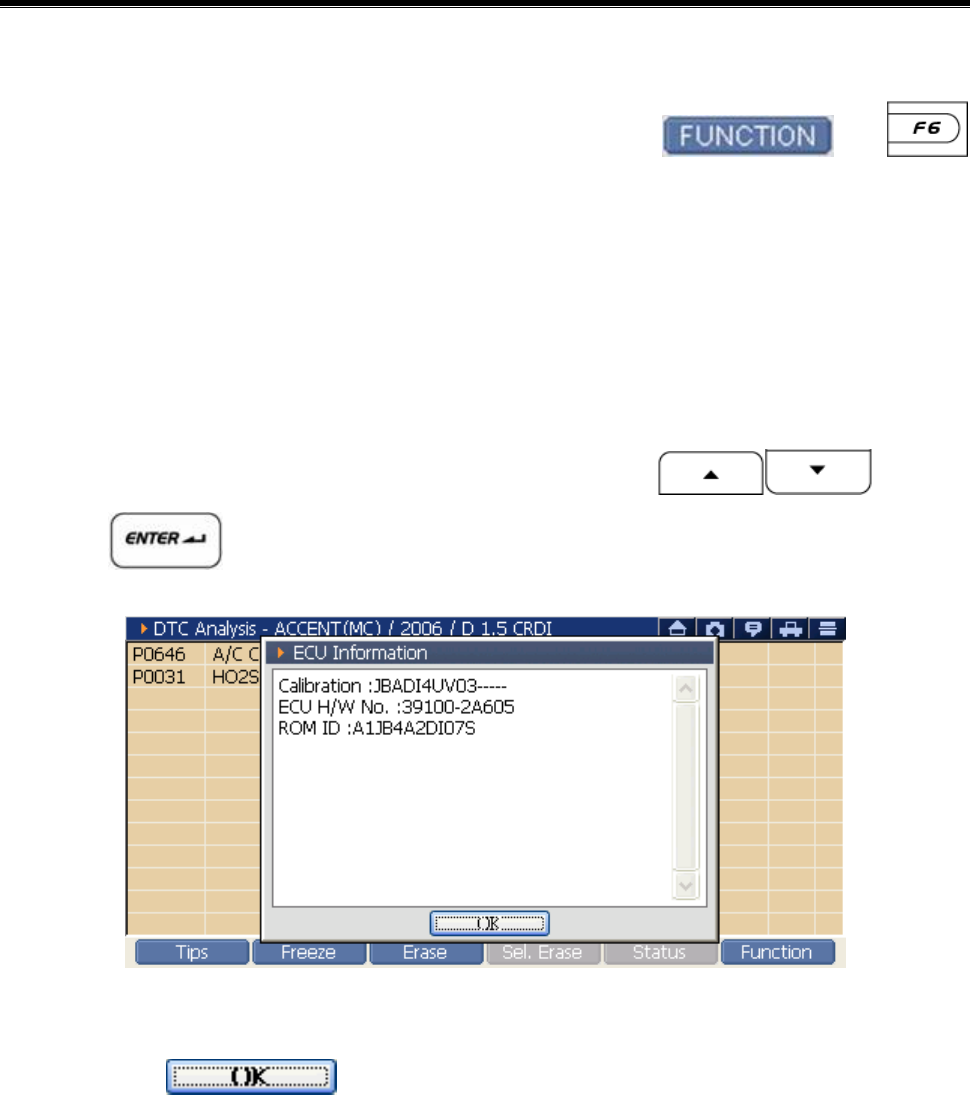
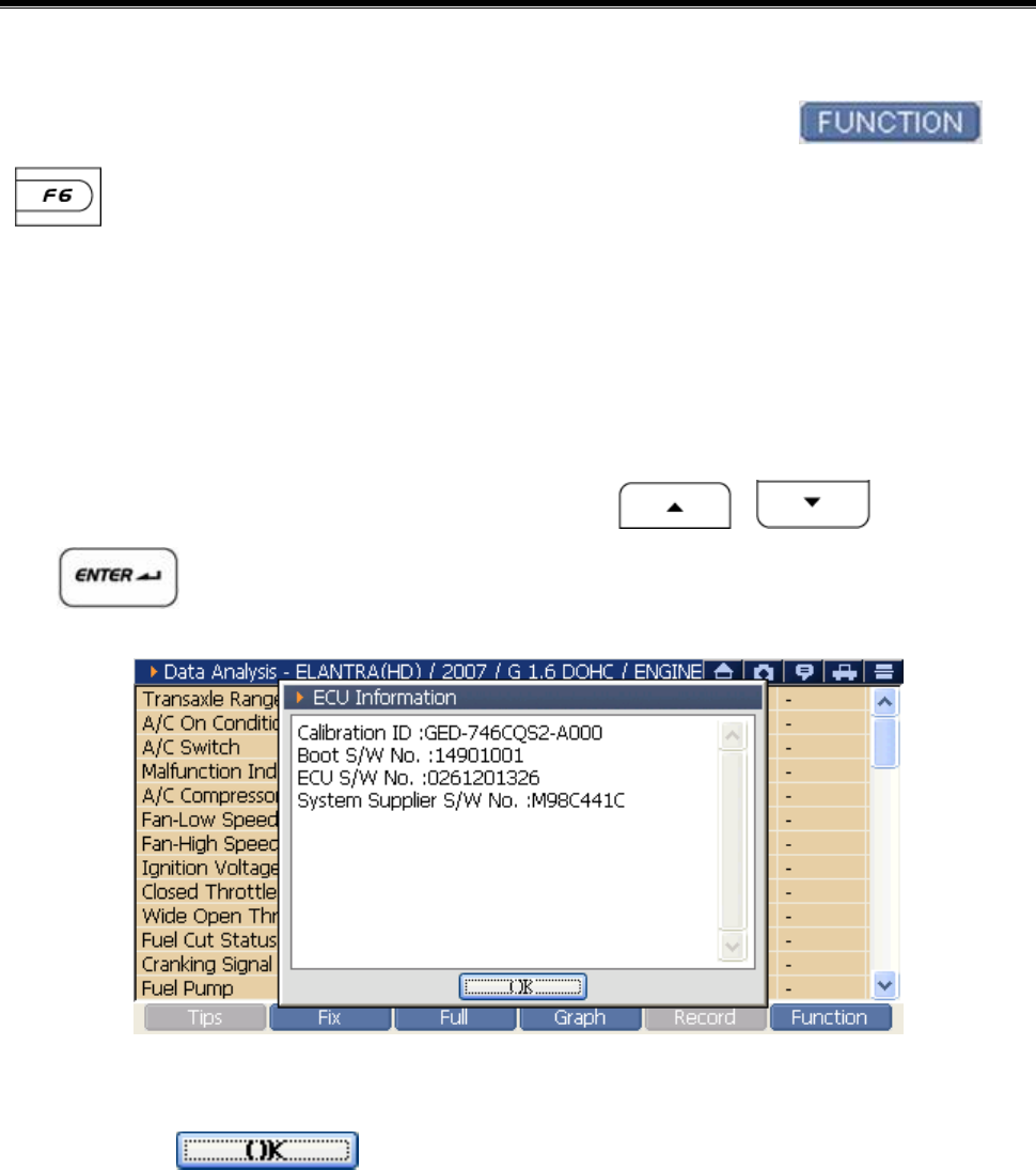
Check the ECU Information
1) On the <Figure 1> DTC Analysis screen, select or ,
then the Function Menu is shown as in <Figure 6>.
Selecting the ECU Info in the showing menu, the screen changes to the
ECU Information as shown in <Figure 9>.
Using the stylus pen, select on the touch screen directly.
After moving cursor using the H/W buttons , press
the button.
<Figure 9: ECU Information>
2) Press the button at the bottom of the “ECU Information”
to close the window.
User’s Manual
- 88 -
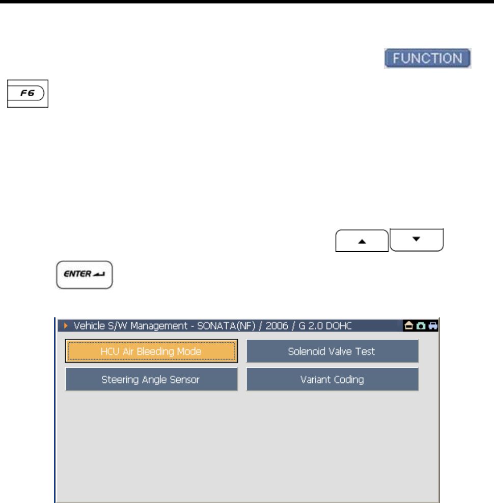
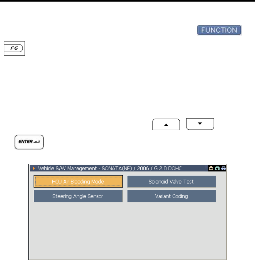
Change to the Vehicle S/W Management
1) On the <Figure 1> DTC Analysis screen, select the or
, then the Function Menu is shown as <Figure 6>.
2) Select the Vehicle S/W Management in the showing menu, the screen
changes to the Vehicle S/W Management as <Figure 9>.
Using the stylus pen, select on the touch screen directly.
After moving cursor using the H/W buttons , press
the button.
<Figure 10: Vehicle S/W Management>
User’s Manual
- 89 -
Data Analysis
Vehicle COM Function Module NO: A-04-004
It is the diagnosis item for checking the data input/output status of the
control mode to be diagnosed through the service data.
There are 3 methods for using the service data.
z Select the on the main screen
→ Move to the “Data Analysis” of main diagnosis system set in the
System Selection.
z Select the at the “Fault Code Searching”
→ Move to the “Data Analysis” of the control module having DTC
selected in the “Fault Code Searching”.
z Select the in the “DTC Analysis” and select the Current
Data among the showing menu
→ The “DTC Analysis” and “Data Analysis” of the control module
communicated in the “DTC Analysis” are output in dual mode at the
same time.
User’s Manual
- 90 -
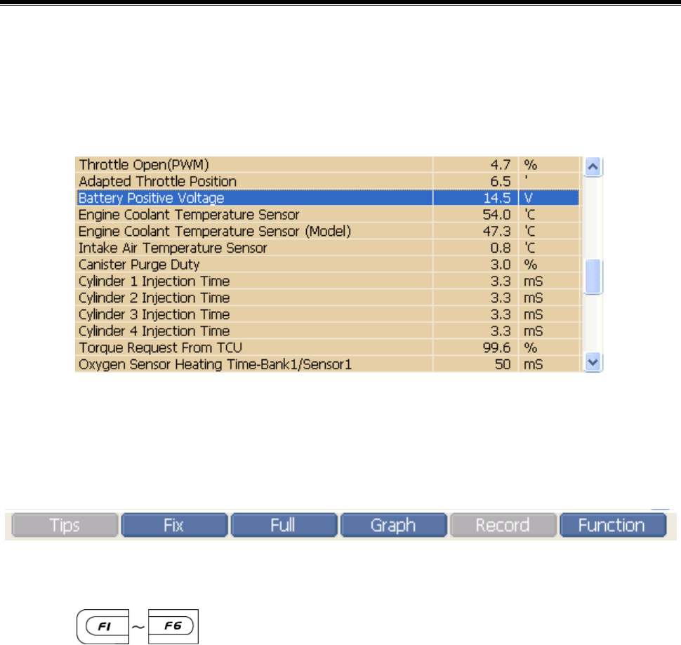
Introduction of Service Data screen
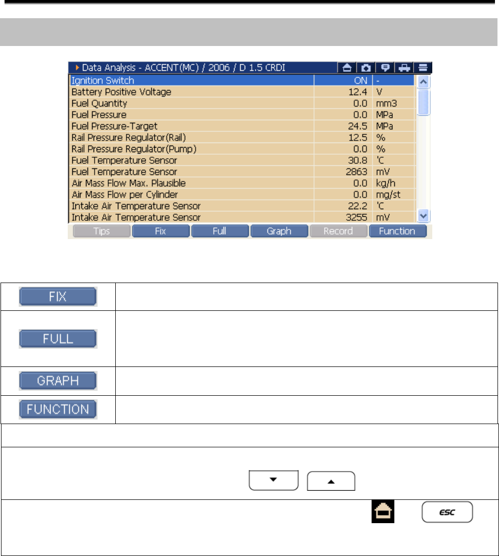
<Figure 1: Data Analysis Screen>
Fix the selected item at the top of the screen.
Split the service data screen into left and right sides
and show the 26 data at maximum.
Show the fixed item in line graph.
Change to dual mode and use other functions.
Reference
z If the wanted item is not shown, move the scroll bar with the stylus
pen or use the direction buttons to find it.
z If you want to return to initial screen, press the or at
the right upper side of screen
User’s Manual
- 91 -
Operating Sequence and References
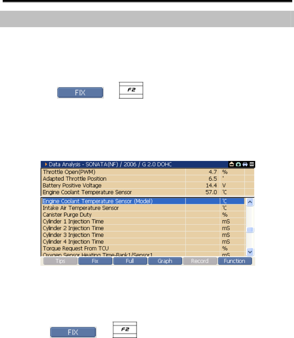
Fix the Data Item
z How to fix the Data item
1) Select the item want to fix.
2) Select the or at the bottom of the screen or
double click the item using the stylus pen on the touch screen,
then the selected item will be fixed at the top of the screen as
shown in <Figure 2>.
<Figure 2: Fix the Data Item>
z Release the fixed Data item
1) Select the fixed item again.
2) Select the or at the bottom of the screen or
double click the item to be released using the stylus pen on the
touch screen.
Tips
* The number of Fix is 4 at most in single mode and 2 at most in dual
mode.
User’s Manual
- 92 -
Full
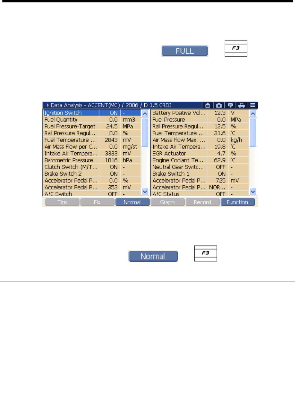
z See with Full screen
On the service data screen, select or , then the
screen will be divided as shown in <Figure 3> and 26 data items are
shown.
<Figure 3: See in Full>
z Return to Normal screen
On Full screen mode, press or .
Note:
On the screen in Full mode, FIX and Graph functions are not
available.
Find the item now shown on the screen using the arrow button or
moving the scroll bar with the stylus pen.
If all of item names are not shown, select the item using the
stylus pen, then all item name can be shown by moving it to right
side.
User’s Manual
- 93 -
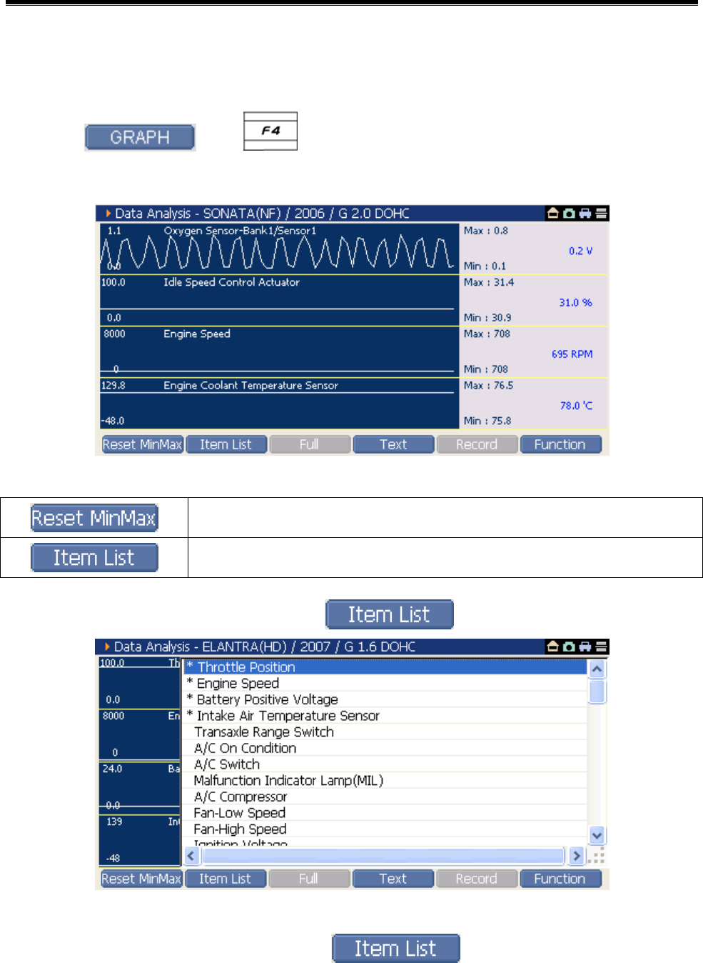
Graph
1) Fix the item want to see in graph.
2) Select or , then the selected item will be
shown in graph mode as in <Figure 4>.
<Figure 4: Graph Mode>
Initialize the Max and Min values output on graph.
Modify the item list on the graph.
* Add/Delete the graph list using
<Figure 5: Item List>
① In the graph mode, select , then Item List is shown
as in <Figure 5>.
User’s Manual
- 94 -
(The item having “*” mark among the Item List means the item
shown in graph mode currently.)
② Select the item want to be deleted among the list shown in graph
mode currently using the arrow buttons and
key or using the stylus pen on the touch screen.
③ Select the item want to be shown in graph mode among the list
not shown in graph mode using the arrow buttons
and key, or using the stylus pen on the touch
screen.
3) If you want to return to the service data, press the or
.
Note:
* The number of service data possible to applied to Graph mode is 4 at
most in single mode, and 2 at most in dual mode.
User’s Manual
- 95 -
Data Analysis Dual Diagnosis Mode
See the Data Analysis and the DTC Analysis at the same time
1) On the <Figure 1> DTC Analysis screen select or
, the Function Menu will be shown as in <Figure 6>.
<Figure 6: DTC Analysis “Function Menu”>
2) On the showing menu, select the Current Data to change the screen
to the Dual mode as shown in <Figure 7>.
Using the stylus pen, select on the touch screen
Moving the cursor with H/W buttons , , press
the key.
<Figure 7: Data Analysis & DTC Analysis Dual Diagnosis Mode>

User’s Manual
- 96 -
See the DTC Analysis and the Actuation Test at the same time
1) On the <Figure 1> DTC Analysis screen, select or
, the Function Menu will be shown as in <Figure 6>.
2) On the showing menu, select the Current Data, the screen will be
changed to the Dual mode as shown in <Figure 8>.
Using the stylus pen, select on the touch screen directly.
Moving the cursor with H/W buttons , , press
the key.
<Figure 8: Data Analysis & Actuation Test Dual Diagnosis Mode>
User’s Manual
- 97 -
Check the ECU Information
3) On the <Figure 1> Data Analysis screen, select or
, the Function Menu will be shown as in <Figure 6>.
4) On the showing menu, select the ECU Info, then the ECU Information
popup window as in <Figure 9> is shown.
Using the stylus pen, select on the touch screen directly.
Moving the cursor with H/W buttons , , press the
key.
<Figure 9: ECU Information>
5) Press the button at the bottom of the “ECU Information”
to close the window.
User’s Manual
- 98 -
Change to Vehicle S/W Management
3) On the <Figure 1> Data Analysis screen, select or
, the Function Menu will be shown as in <Figure 6>.
On the showing menu, select the ECU Info, then the screen will be
changed to the Vehicle S/W Management as in <Figure 9> is shown.
Using the stylus pen, select on the touch screen directly.
Moving the cursor with H/W buttons , , press the
key.
<Figure 10: Vehicle S/W Management>
User’s Manual
- 99 -
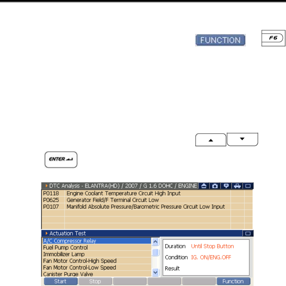
Actuation Test
Vehicle COM Function Module NO: A-04-005
Through the "Actuation Test", it is possible to check if the control
module and unit to be tested are defected or not.
There are two methods for using “Actuation Test”.
z At the “DTC Analysis”, select the "Actuation Test" of the menu
included in .
Æ “DTC Analysis” and "Actuation Test" are output in dual mode.
z At the “Data Analysis”, select the "Actuation Test" of the menu
included in .
Æ “DTC Analysis” and "Actuation Test" are output in dual mode.
User’s Manual
- 100 -
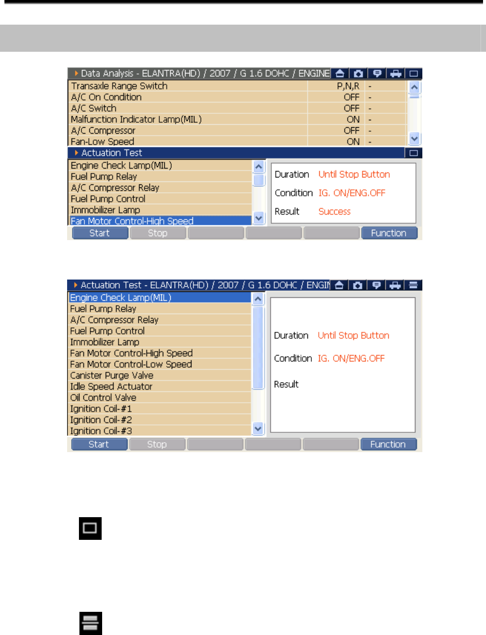
<Figure 1: Actuation Test& Data Analysis>
<Figure 2: Actuation Test overall screen>
Change to the "Actuation Test" overall screen:
Select the indicated by the arrow in <Figure 1>, then screen will be
changed to the overall screen.
Change to the Dual Mode Previous on Overall screen:
Select the at the upper right side of <Figure 2>, then the screen will
be change to the dual mode previous on overall screen.
Description of Actuation Test screen
User’s Manual
- 101 -
Left Zone of "Actuation Test" Screen:
You can see the “Actuation Test” item. For check the item, move the
scroll bar using the stylus pen or using the direction buttons
.
Right Zone of "Actuation Test" Screen:
You can check the Testing Lap Time, Test Condition and Test Result.
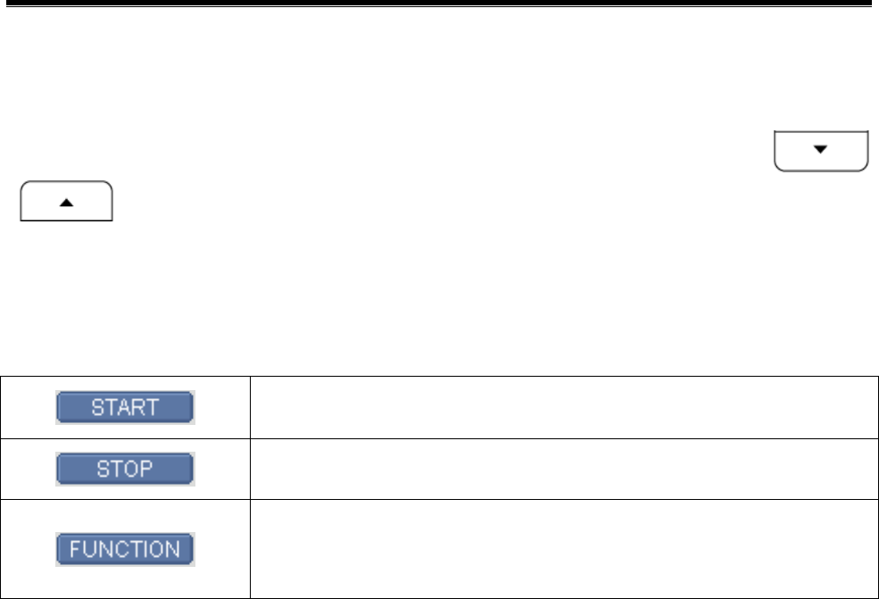
Start the test for the selected item.
Finish the test of selected item.
Change to the Current Data, DTC, ECU Info, or
Vehicle S/W management.
User’s Manual
- 102 -
1) Select the Actuation Test item
At the left zone of “Actuation Test” screen, select using stylus pen on
the touch screen or move the cursor using direction buttons
.
2) Check and setup the Actuation Test condition
After checking the Test Lap Time and Test Condition at the right zone
of “Actuation Test” screen, setup them according to the condition of
the testing vehicle.
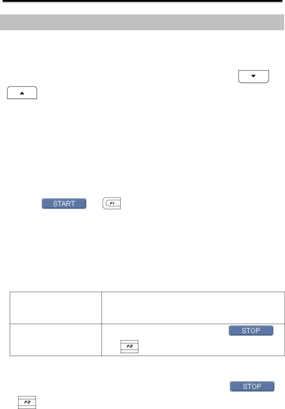
3) Start the Actuation Test
Select or to start the test.
4) Check the Actuation Test result
On the right zone of the “Actuation Test” screen, the test result
(Failure or Success) will be shown.
5) Stop the Actuation Test
Test which lap time is
determined:
After completing test time, the test will be
terminated automatically.
Test which lap time is
not determined:
After checking the result, select
or to terminate the test.
Note:
Even it is the test which lap time is determined, press the
or during test, then it will be terminated.
How to execute the Actuation Test
User’s Manual
- 103 -
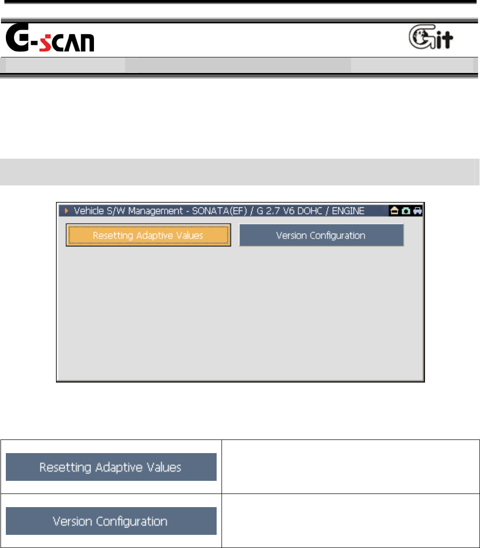
Vehicle S/W Management
Vehicle COM Function Module NO: A-04-006
It is the function for diagnosing all items except the fault searching,
service data, actuator test. For exact diagnosis, it supports various
diagnosis functions by system.
Diagnosis Supplementary Function Main Screen
<Figure 1: Vehicle S/W Management Screen>
Function for initializing the teaching
value in ECU.
Function for setting the option such
as ABS and TCS configured in ECU.
Note:
This screen is the main screen for supplementary diagnosis function of
specific vehicle. According to the system, the screen for diagnosis
supplementary function may be different.
User’s Manual
- 104 -
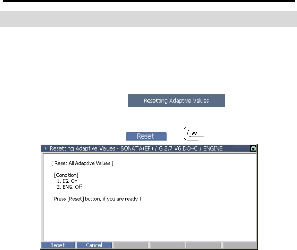
Example of Diagnosis Supplementary Function
Resetting Adaptive Values
The "Resetting Adaptive Values" function is used to reset adaptive learn
data on specific ECUs.
z On the main screen, select , then screen will
show the window as in <Figure 2>. After checking the sentence
shown in screen, press the or .
<Figure 2: Resetting Adaptive Values step 1>
User’s Manual
- 105 -
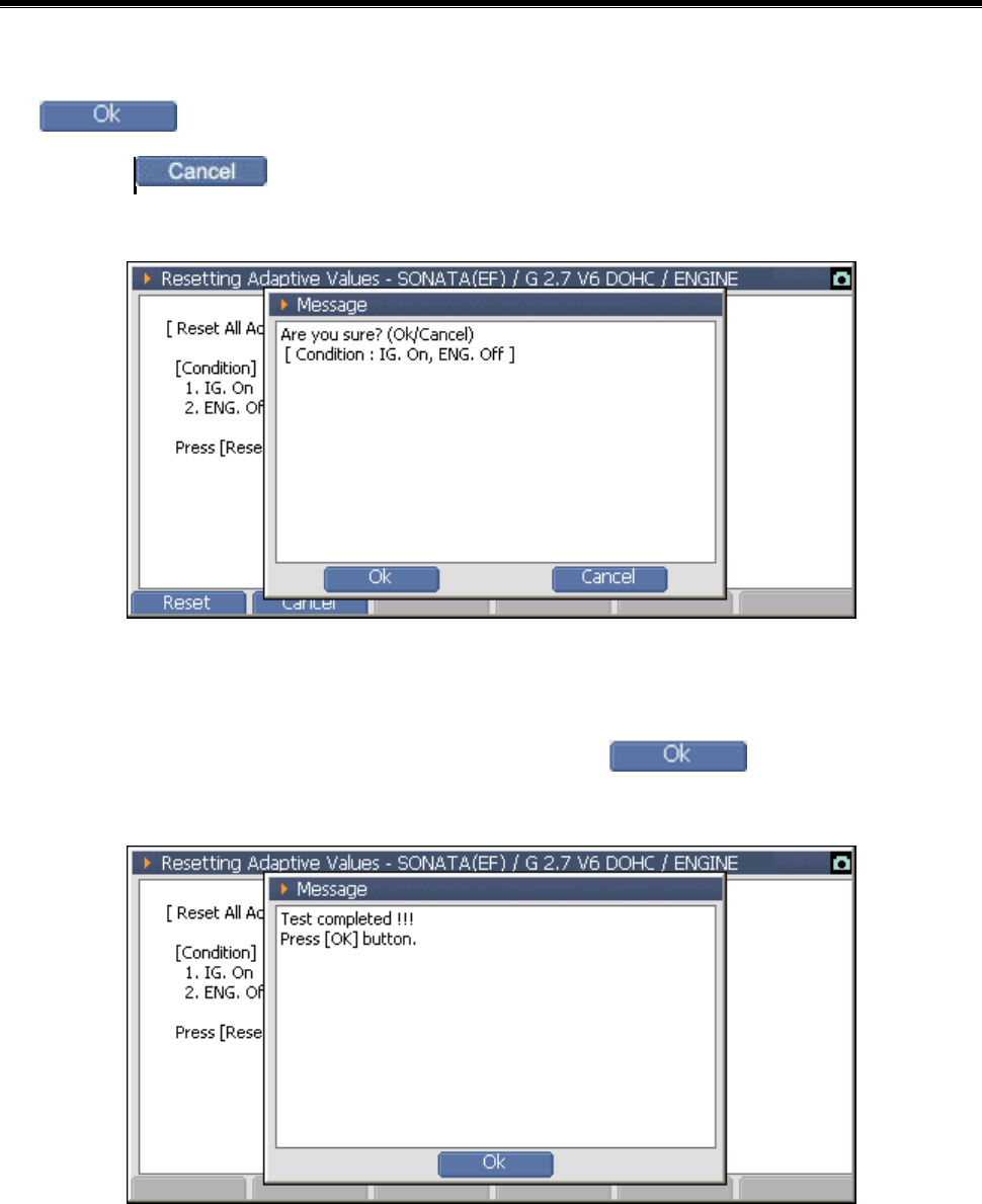
z After checking the sentence shown in the message window, press
button to initialize the ECU teaching value.
* Select , then the option setup will be cancelled and the
message window will be closed.
<Figure 3: Resetting Adaptive Values step 2>
z Checking the following message, press to complete the
initialization of ECU teaching value.
<Figure 4: Resetting Adaptive Values step 3>
User’s Manual
- 106 -
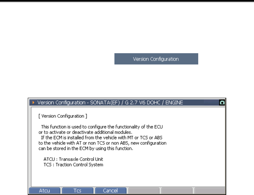
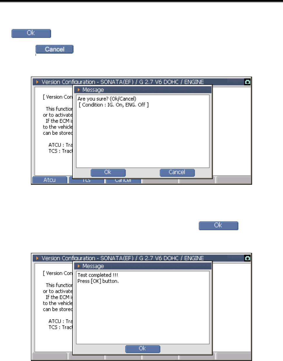
Version Configuration
The "Version Configuration" function is used on supported engine
ECUs to conFigure for transaxle and ABS ECU options.
On the main screen, select then following
window will be shown. After checking the sentence on the screen,
select the proceeding item.
<Figure 5: Version Configuration step 1>
User’s Manual
- 107 -
z After checking the sentence on the message window, press the
button.
* Select to cancel the option setup and to close the message
window.
<Figure 6: Version Configuration step 2>
z After showing the following message, press . Then the
ECU option setup is completed.
<Figure 7: Version Configuration step 3>
User’s Manual
- 108 -
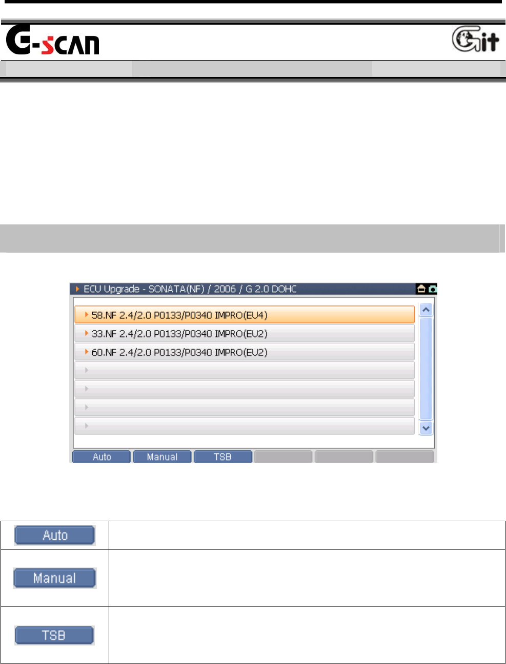
ECU Upgrade
Vehicle COM Function Module NO: A-04-006
It is the function for modifying the ECU program to enhance the
performance of ECU. Before using this function, be familiar with the
cautions and then perform the ECU upgrade. The ECU upgrading not
comply with the cautions may cause serious damages on the ECU.
Introduction of the ECU Upgrade screen
<Figure 1: ECU Upgrade Screen>
Upgrade the ECU for the selected event automatically.
For the case not to upgrade automatically, upgrade the
ECU in manual.
Show the Technical Service Bulletin of selected event.
It should be checked before updating.
User’s Manual
- 109 -
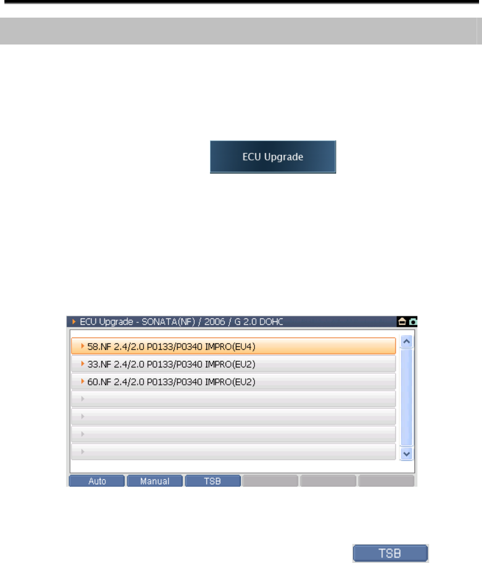
How to ECU Upgrade
How to use the Auto Upgrade
When the ECU of relating vehicle has the update event not applied, the
auto update is conducted in the Auto Mode.
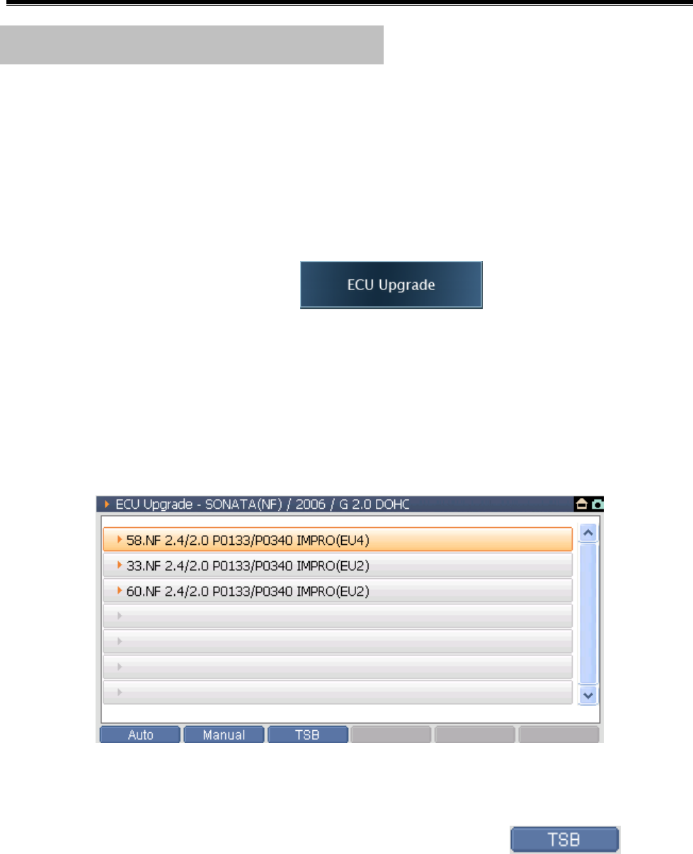
1) On the main screen, select , then screen will be
changed to the event selection screen as in the following figure, and
all events applied to the vehicle are shown. If there is no event
applied to the ECU of the vehicle, it is not changed from the main
screen to the event selection screen.
<Figure 2: ECU Upgrade Screen>
Notice:
After selecting the event to be upgraded, select at the
bottom of the screen to perform the update after checking the
Technical Service Bulletin.
User’s Manual
- 110 -
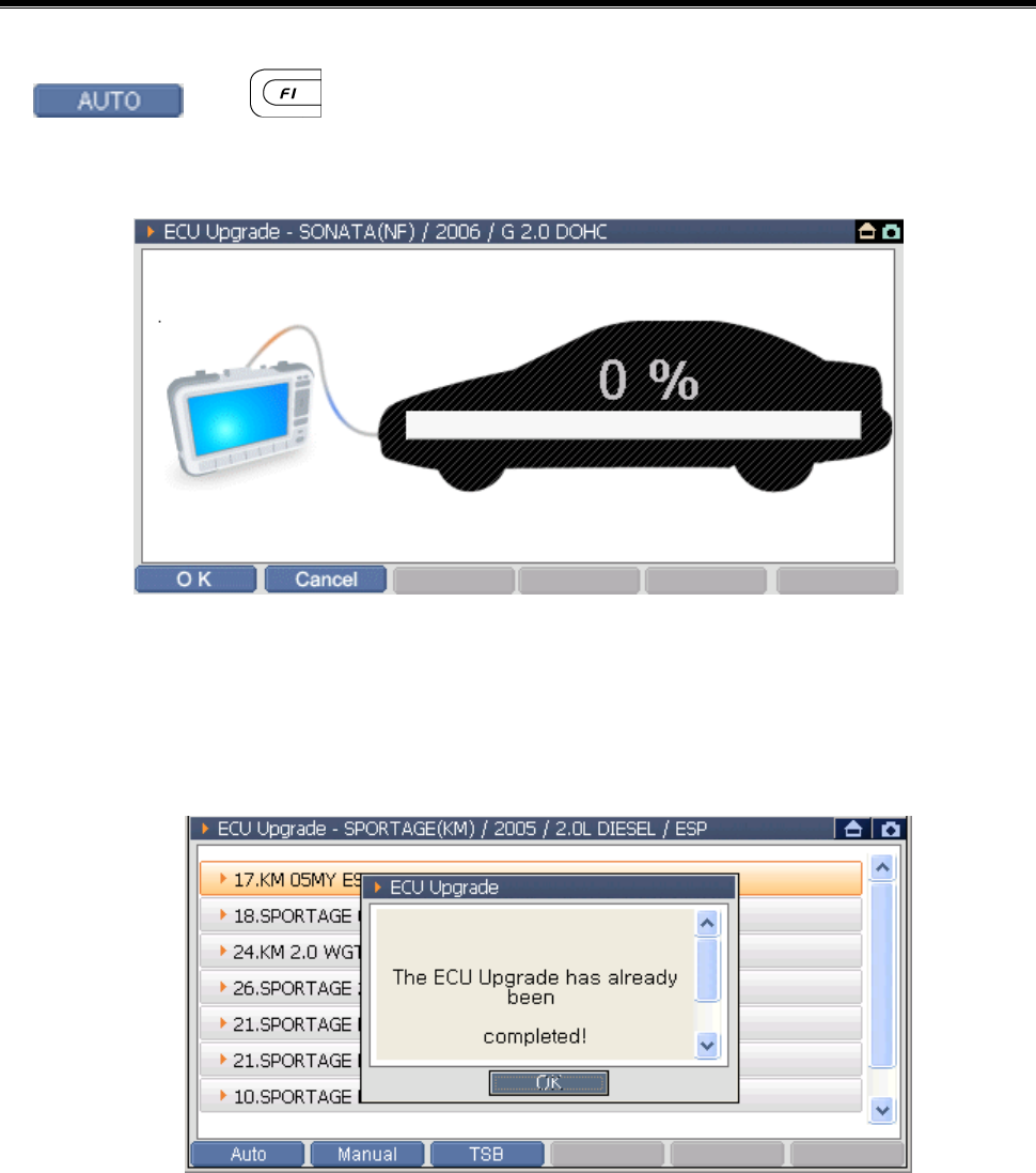
2) After selecting the event on the event selection screen, select
or , then the screen will be changed to the ECU
update preparing screen as follows.
<Figure 3: ECU Auto Upgrade step 1>
Error Message:
When the selected event is already applied to the vehicle
<Figure 4: ECU Auto Upgrade step 2>
User’s Manual
- 111 -
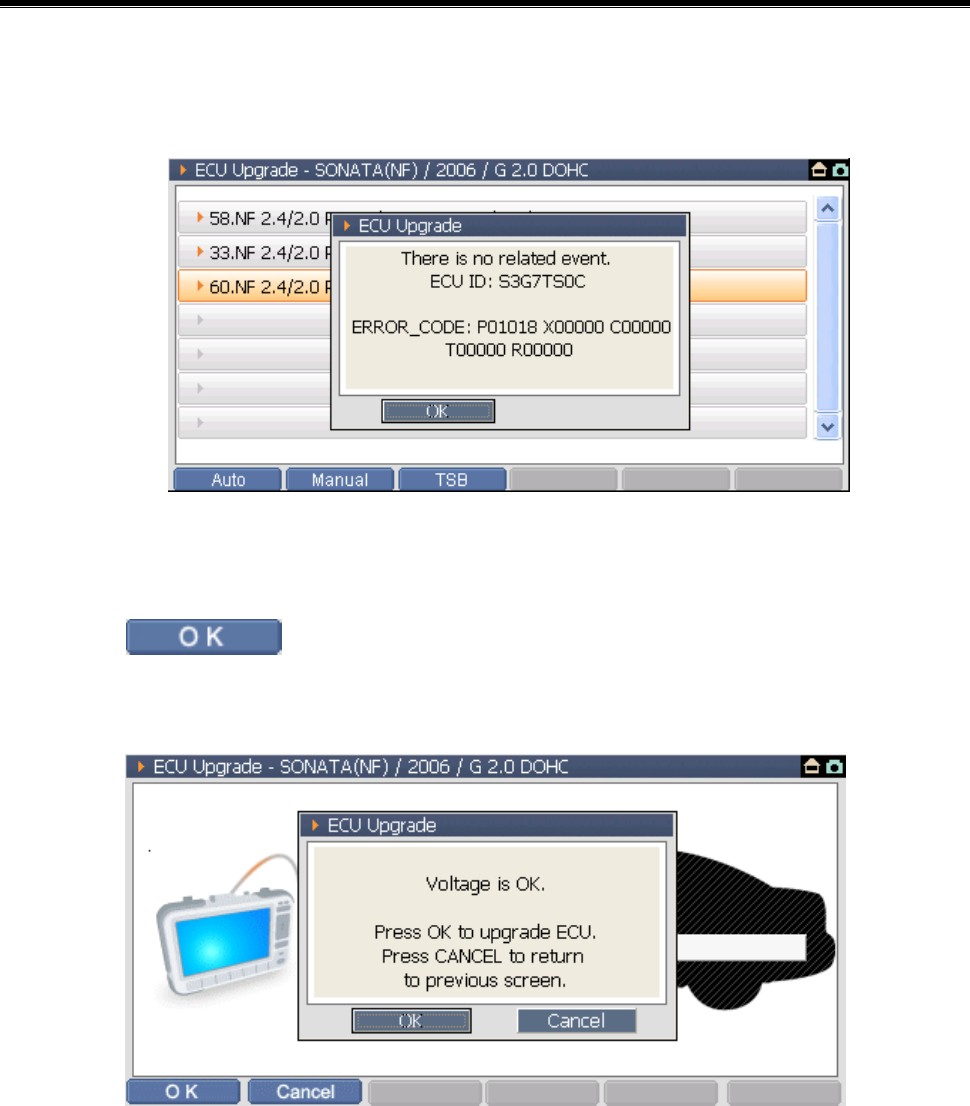
When there is no event related to the ECU specification of the
vehicle
<Figure 5: ECU Auto Upgrade step 3>
3) Select button at the bottom of the update proceeding
window screen, then following message will be shown.
<Figure 6: ECU Auto Upgrade step 4>
User’s Manual
- 112 -
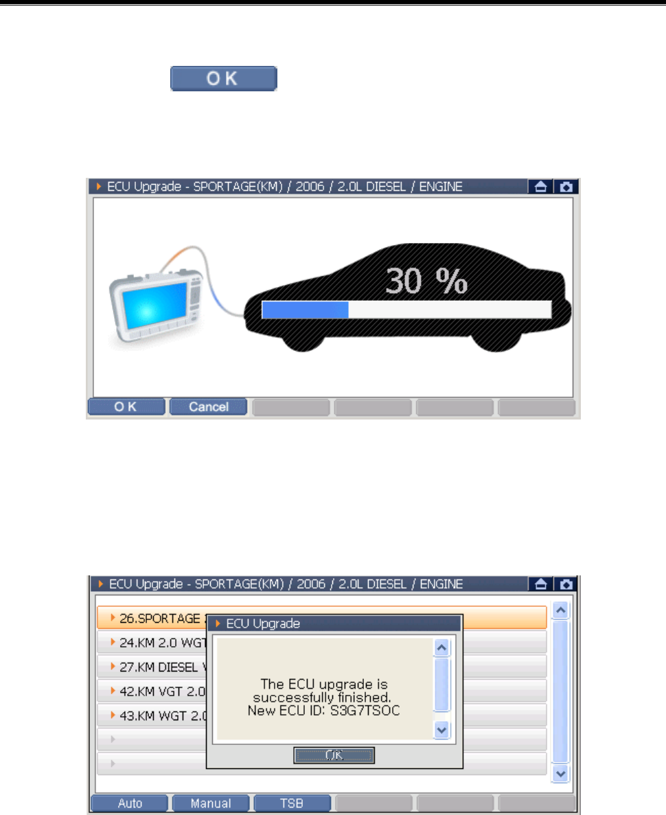
4) After checking the battery voltage of the vehicle, if there is no voltage
problem, select button, then update will be started as
shown in following figure.
<Figure 7: ECU Auto Upgrade step 5>
5) After completing all ECU update procedure, the following message
will be shown.
<Figure 8: ECU Auto Upgrade step 6>
User’s Manual
- 113 -
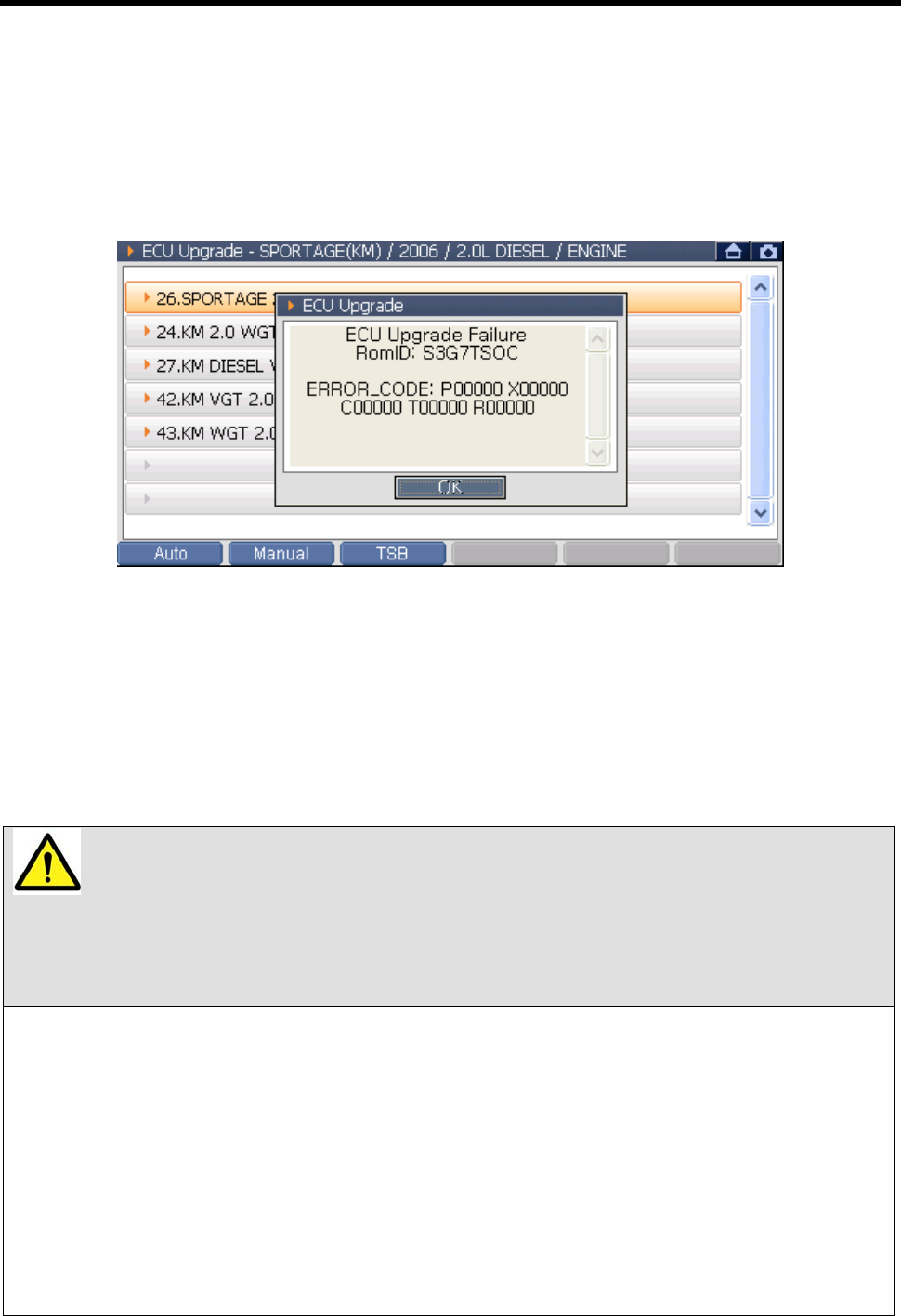
If an error is occurred during updating the ECU, the following
message will be shown. Then, using manual upgrade, conduct the
upgrade in force.
<Figure 9: ECU Auto Upgrade step 7>
Cautions for processing
The time required to complete an upgrade will vary. Menus and
buttons are all disabled during the upgrade process.
CAUTIONS
Following instructions should be kept during the upgrade process,
or else ECU could be damaged.
z Do not start the engine or turn the ignition key OFF.
z Do not operate any vehicle accessories during the upgrade
process.
z Do not disconnect the G-scan during the upgrade process.
z Review the TSB (Technical Service Bulletin) before upgrade, as
upgrade procedures can be different for each event.
Module: A-05-001 (p.07)
User’s Manual
- 114 -
How to conduct the Manual Upgrade
The manual mode is the ECU upgrade mode used when event is applied
in force even there is no event to be applied to the ECU of the vehicle.
Unlike the auto mode, in order to apply the event to the ECU of the
vehicle, the user directly selects the event and enters the password.
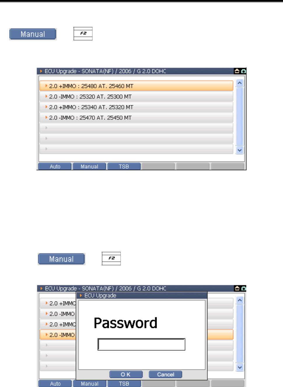
1) On the main screen, select , then the screen will
be changed to the screen as shown in following figure and all events
applied to the vehicle are shown. If there is no event applied to the
ECU of the vehicle, it is not changed from the main screen to the
ECU upgrade screen.
<Figure 10: ECU Upgrade Screen>
Caution:
After selecting the event to be upgraded, select at the
bottom of the screen to perform the update after checking the
Technical Service Bulletin.
User’s Manual
- 115 -
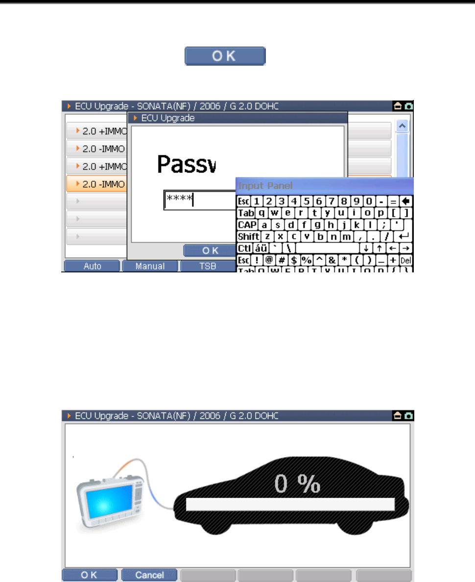
2) After selecting the event on the event selection screen, press
or , then the screen will be changed to the system
selection screen as shown in following figure.
<Figure 11: ECU Manual Upgrade step 1>
Note:
It is changed to the system selection screen. Select the system comply
with the vehicle specification.
3) Select or , then the message window for entering
the password as following figure.
<Figure 12: ECU Manual Upgrade step 2>
User’s Manual
- 116 -
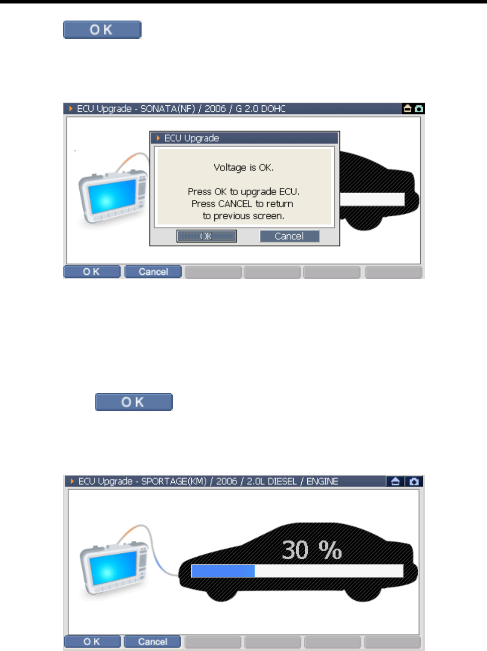
4) After entering the password using the stylus pen as shown in
following figure, select button at the bottom of the
message window.
<Figure 13: ECU Manual Upgrade step 3>
5) If the password is correct, the following update preparing screen will
be shown
<Figure 14: ECU Manual Upgrade step 4>
User’s Manual
- 117 -
6) Select button at the bottom of the update proceeding
window, then following message will be shown.
<Figure 15: ECU Manual Upgrade step 5>
7) After checking the battery voltage of the vehicle, if there is no problem,
then select button to start the update as shown in the
following figure.
<Figure 16: ECU Manual Upgrade step 6>
User’s Manual
- 118 -
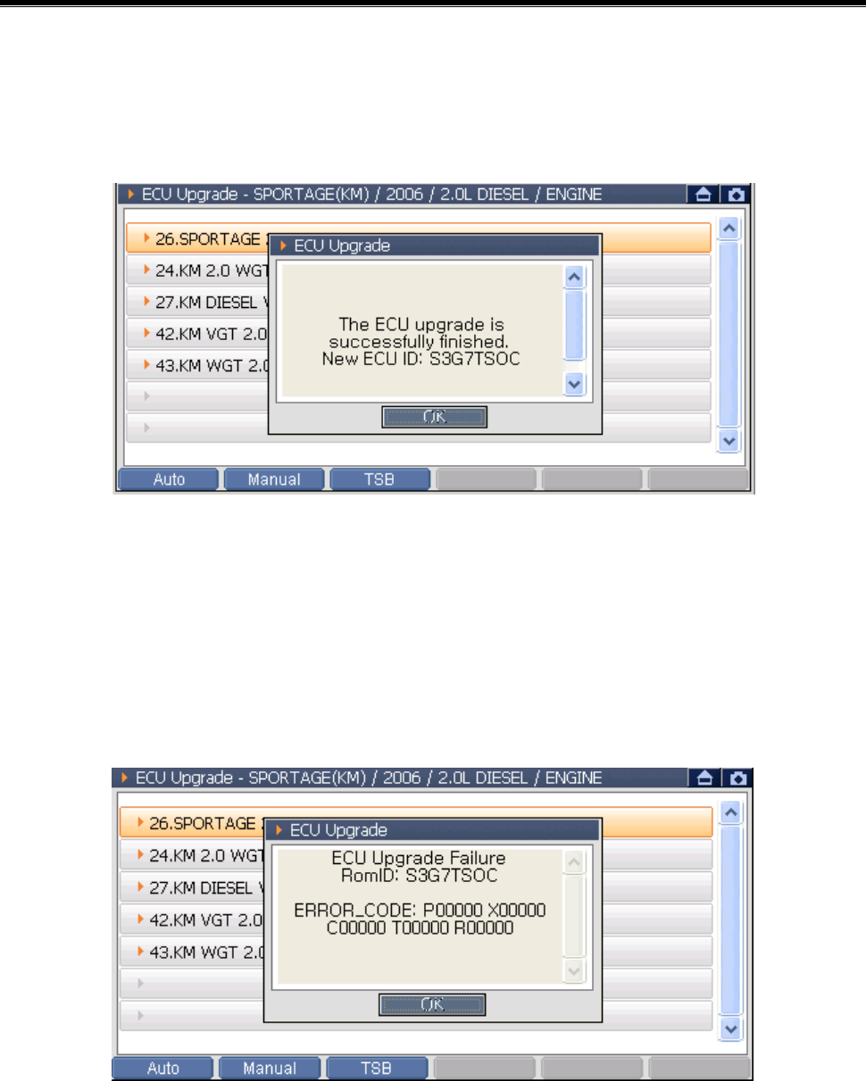
8) After completing all ECU updates, the following message will be
shown.
<Figure 17: ECU Manual Upgrade step 7>
Error Message
If any error is occurred during updating the ECU, the following
message will be shown.
<Figure 18: ECU Manual Upgrade step 8>
User’s Manual
- 119 -
Cautions for processing
The time required to complete an upgrade will vary. Menus and
buttons are all disabled during the upgrade process.
CAUTIONS
Following instructions should be kept during the upgrade process,
or else ECU could be damaged.
z Do not start the engine or turn the ignition key OFF.
z Do not operate any vehicle accessories during the upgrade
process.
z Do not disconnect the G-scan during the upgrade process.
z Review the TSB (Technical Service Bulletin) before upgrade, as
upgrade procedures can be different for each event.
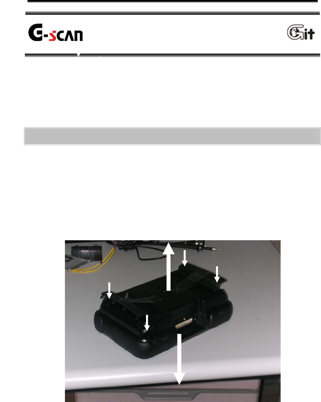
User’s Manual
- 120 -
The rechargeable battery and TPMS module embedded into G-scan are
the optional items.
The optional items should be installed to the G-scan according to the
method described in the manual. Otherwise, it may cause defects on the
product.
Battery & TPMS Pack Installation
1) Loosen the Package mounting bolts from the 4 points shown in
<Figure 1> with ①.
2) Disconnect the body module and Pack to the direction ② as shown in
<Figure 1> carefully.
(If excessive force is applied, the product may be damaged.)
3) Install the Battery Pack (or TPMS Pack) as the same figure of the
previous Pack condition.
4) Tighten the 4 mounting bolts loosened at step 1).
<Figure 1 Position of the Pack Mounting Bolt>
Optional Item Installation and
Expenditure Exchange
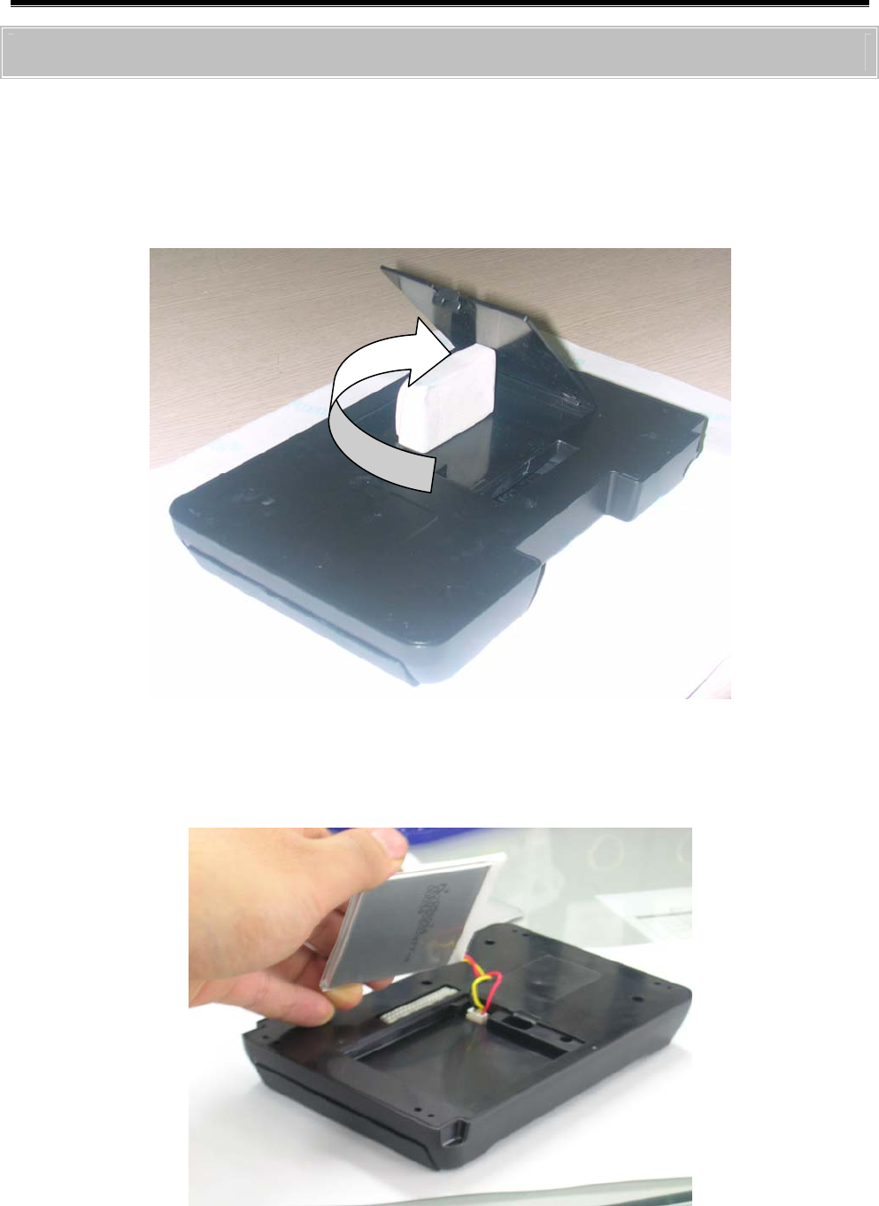
User’s Manual
- 121 -
Exchanging the Rechargeable Battery
1) For installation and removal of the Pack, refer to the Battery Pack &
TPMS Pack Installation.
2) Open the battery cover of Pack disassembled like the ① shown in
<Figure 2>.
<Figure 2 Open the battery cover>
3) Remove the used battery like the ① as shown in <Figure 3>.
<Figure 3 Remove the battery>
User’s Manual
- 122 -
4) Checking the battery terminal shape of the new rechargeable battery,
insert it properly.
<Figure 4 Install the New battery>
5) Locate the new rechargeable battery into the case correctly.
6) Close the rechargeable battery and assemble the pack according to
the manual.
Caution
z Be careful of the connector direction not to change the polarity of
the rechargeable battery.
z After installing the connector, be careful that the battery wiring is
not damage by the battery cover.
z After the rechargeable battery cover is closed completely, the
Pack should be mounted on the body module.
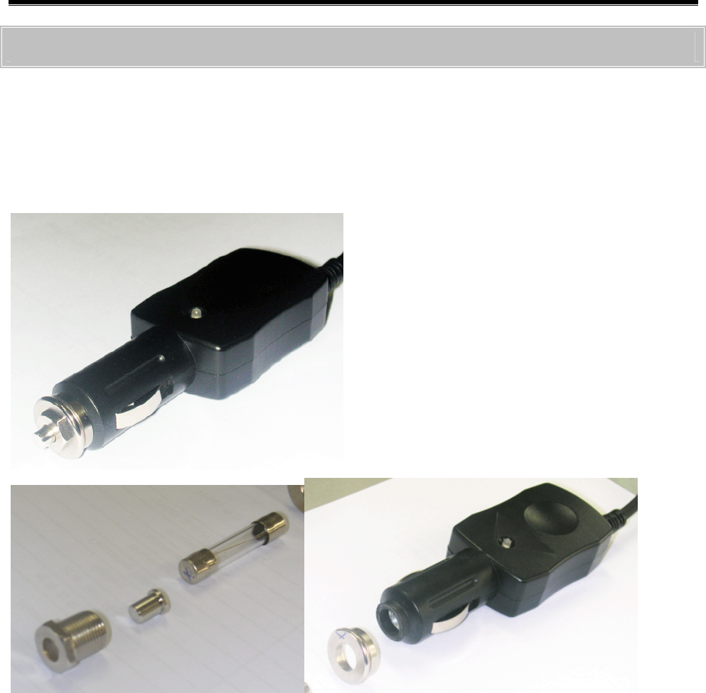
User’s Manual
- 123 -
Exchanging the Cigar-Cable Fuse
1) Turning the portion marked in the <Figure 5> to the counter
clockwise direction with the 10mm Hexagonal wrench, it is
disassembled as shown in <Figure 5>.
<Figure 5 Disassemble the Cable – Cigar>
2) After exchanging the fuse (250V 4A), assemble it in reversed order
of disassemble.

User’s Manual
- 124 -
G-scan and Peripherals Limited Warranty
Providing that this product has been installed and used as instructed in
the operation manual, Global Information Technology (referred to as
“GIT”) will repair G-scan module (main body other than software, which
is covered by a separate warranty) with new or rebuilt parts, free of
charge for three (3) years from the date of original purchase in the event
of a defect in materials or workmanship. This warranty excludes all other
options and accessories, which are covered for a period of one (1) year
from the date of original purchase.
This warranty is extended solely to the original purchaser. A purchase
receipt or other proof of evidencing the date of original purchase will be
required before warranty service is provided.
This warranty only covers failures due to defects in materials or
workmanship, which may occur during normal use. It does not cover
damage which occurs in shipment or failures which may be caused by
products not supplied by GIT, or failures resulting from alteration,
accident, misuse, introduction of liquid material or other foreign matter
into the product, abuse, neglect, installation, maladjustment of consumer
controls, improper maintenance, modification or service by anyone other
than GIT, or damage to be attributable to acts of God.
GIT SHALL NOT BE LIABLE FOR LOSS OF DATA OR OTHER INCIDENTAL
OR CONSEQUENTIAL DAMAGES RESULTING FROM THE USE OF THIS
PRODUCT, OR ARISING OUT OF ANY BREACH OF THIS WARRANTY. ALL
EXPRESS AND IMPLIED WARRANTIES, INCLUDING THE WARRANTIES OF
MERCHANTABILITY AND FITNESS FOR A PARTICULAR PURPOSE ARE

User’s Manual
- 125 -
LIMITED TO THE APPLICABLE WARRANTY PERIOD SET FORTH ABOVE.
GIT’s entire liability, and your exclusive remedy under this warranty shall
be limited to the replacement, of any defective parts or functions in the
product, which is returned to GIT’s Service Center, together with a copy
of the purchase receipt, during the aforementioned warranty period.
Anything in the foregoing to the contrary notwithstanding, GIT shall have
no obligation for any defects in the product resulting from your storage
thereof, or for defects that have been caused by operation of the
product other than on the operation manual or in environmental
conditions other than those specified by GIT or by alteration, accident,
misuse, abuse, neglect, mishandling, misapplication, installation,
maladjustment of consumer controls, improper maintenance,
modification of damage that is attributable to acts of God.
This limited warranty gives you specific legal rights, and you may also
have other rights, which vary from country to country. The laws of
Republic Korea, without regard to its conflict-of-laws rules, will govern
this Limited Warranty.
To obtain help or technical Assistance, please contact your product
supplier or distributor.
User’s Manual
- 126 -
Dis
p
osal of Old Electrical and
Electronic Equipment
WEEE (Waste Electrical and Electronic Equipment) symbol shown in
[Figure 1] is indicated on the back of the G-scan main module
Please follow the regulation guide for disposal of Waste Electrical and
Electronic Equipment.
[Figure 1] WEEE Symbol
Disposal of Old Electrical & Electronic Equipment (Applicable in the
European Union and other European countries with separate collection
systems)
This symbol on the product or on its packaging indicates that this
product shall not be treated as household waste. Instead it shall be
handed over to the applicable collection point for the recycling of
electrical and electronic equipment. By ensuring this product is disposed
of correctly, you will help prevent potential negative consequences for
the environment and human health, which could otherwise be caused by

User’s Manual
- 127 -
inappropriate waste handling of this product. The recycling of materials
will help to conserve natural resources. For more detailed information
about recycling of this product, please contact your local city office,
your household waste disposal service or the shop where you purchased
the product.