GMC XL 01082803EN To The Manual 645cf67c Ae03 4b96 Ac9e 66ea2f692eb0
User Manual: GMC XL to the manual
Open the PDF directly: View PDF ![]() .
.
Page Count: 94
User Manual
Magellan
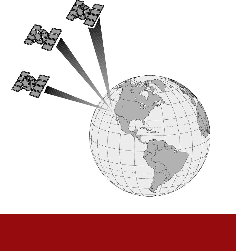
GPS Satellite
Navigator
Meridian XL

WARNINGS
USE GOOD JUDGEMENT
This product is an excellent navigation aid, but does not replace the need for
careful orienteering and good judgement. Never rely solely on one device for
navigating.
USE CARE
The Global Positioning System (GPS) is operated by the U.S. Government, which is
solely responsible for the accuracy and maintenance of GPS.
The accuracy of position fixes can be affected by the periodic adjustments to GPS
satellites made by the U.S. Government and is subject to change in accordance
with the Department of Defense civil GPS user policy and the Federal
Radionavigation Plan.
USE CAUTION
Accuracy can also be affected by poor satellite geometry. When the accuracy
warnings appear on the screen, use the data with extreme caution.
USE PROPER ACCESSORIES
Use only Magellan cables and antennas; the use of non-Magellan cables and
antennas may severely degrade performance or damage the receiver, and will void
the warranty.
LICENSE AGREEMENT
Magellan grants you, the purchaser, the right to use the software sup-
plied in and with MAGELLAN GPS products (the "SOFTWARE") in the
normal operation of the equipment. You may make copies only for your
own personal use and for use within your organization.
The SOFTWARE is the property of MAGELLAN and/or its suppliers and is
protected by United States copyright laws and international treaty provi-
sions; therefore, you must treat this SOFTWARE like any other copyright
material.
You may not use, copy, modify, reverse engineer or transfer this SOFT-
WARE except as expressly provided in this license. All rights not expressly
granted are reserved by MAGELLAN and/or its suppliers.
* * *
No part of this handbook may be reproduced or transmitted in any form
or by any means, electronic or mechanical, including photocopying and
recording, for any purpose other than the purchaser's personal use
without the prior written permission of Magellan Systems Corporation.
© 1996 by Magellan Systems Corporation. All rights reserved.
Magellan™, Meridian XL GPS™, and Backtrack™ are trademarks of
Magellan Systems Corporation.
22-10242-000
Table of Contents
Introduction ........................................................................ 1
Packing List ................................................................................ 1
Conventions Used In This Manual ............................................. 2
Getting Started ................................................................... 3
General Description ................................................................... 3
Connecting Receiver Power....................................................... 4
First Time Use - Initializing the Receiver .................................... 5
Proper Handling - Signal Reception ........................................... 9
Taking your First Fix ................................................................. 10
Saving Your First Waypoint ...................................................... 10
Introduction to Routes .............................................................. 13
Creating a GOTO Route .......................................................... 14
Reference Section ............................................................ 15
General Usage ......................................................................... 15
Turning the Receiver Off.................................................................. 15
Inputting Data ..................................................................................16
Turning the Light ON and OFF ........................................................16
NAV Screens ............................................................................ 17
Viewing the Position Screen ............................................................ 17
Viewing the NAV 1 Screen...............................................................18
Viewing the NAV 2 Screen...............................................................18
Customizing the Nav Screens ......................................................... 19
PLOT Screens.......................................................................... 21
Viewing the POINTER screen .........................................................21
Viewing the PLOT Screen ...............................................................21
Changing the Plotter Scale .............................................................. 22
Using PAN N SCAN......................................................................... 22
Setting a GOTO Using PAN N SCAN ..............................................23
Deleting Plotter Track ...................................................................... 23
Viewing the ROAD Screen ..............................................................24
Waypoints................................................................................. 24
Saving a Position Fix as a Waypoint ...............................................24
Creating a Waypoints ......................................................................26
Accessing the Waypoint Menu ........................................................26
Viewing a Waypoint ......................................................................... 27
Accessing the Waypoint Function Menu.......................................... 28
Projecting a Waypoint...................................................................... 28
Editing a Waypoint........................................................................... 29
Deleting a Waypoint......................................................................... 30
Routes ...................................................................................... 31
Activating a GOTO Route ................................................................ 31
Accessing the Route Menu.............................................................. 32
Creating a Multileg Route ................................................................ 32
Activating and Deactivating a Route................................................ 34
Reversing a Route ........................................................................... 34
Viewing the Route Summary (Edit Option) ..................................... 35
Viewing the Legs of a Route............................................................ 35
Inserting a Leg in a Route ............................................................... 35
Deleting a Leg .................................................................................36
Adding a Leg ...................................................................................37
Replacing a Waypoint...................................................................... 38
Navigating (Activating) a Leg........................................................... 38
Deleting a Route .............................................................................. 39
Creating a MOB (Man OverBoard) Route ....................................... 39
Creating a Backtrack Route............................................................. 40
Creating a COORD Route ...............................................................40
Viewing the LAST FIX Trip Summary Screen .................................. 41
Last Fix Buffer .......................................................................... 41
Viewing a LAST FIX......................................................................... 41
SETUP Options ........................................................................ 42
Initializing the Receiver.................................................................... 42
Setting the Coordinate System ........................................................ 43
Setting the Elevation Mode.............................................................. 43
Selecting Time Display ....................................................................44
Setting Velocity Averaging ...............................................................44
Setting Speed Units ......................................................................... 44
Setting Distance Units ..................................................................... 45
Setting Elevation Units .................................................................... 45
Setting North Reference. ................................................................. 45
Selecting Map Datum ...................................................................... 45
Setting NMEA ..................................................................................45
Selecting Baud Rate. ....................................................................... 46
Selecting Waypoint Sort .................................................................. 46
Selecting the Last Fix Interval .........................................................46
Plot Setup ........................................................................................46
Sampling.......................................................................................... 47
Power Lock ...................................................................................... 47
Light Intensity ..................................................................................48
Contrast ........................................................................................... 48
Additional Features .................................................................. 48
Viewing the SAT STATUS Screen ................................................... 48
Viewing the Odometer ..................................................................... 49
Resetting the Odometer and/or Trip Odometer ............................... 49
Viewing the Clock ............................................................................ 49
Setting Alarms .................................................................................49
Viewing the SUN/MOON Screen ..................................................... 50
Simulator ......................................................................................... 51
Deleting Last Fixes ..........................................................................51
Deleting Track from the Plotter Screen ............................................ 51
Delete All Waypoints from Waypoint List ......................................... 52
Clearing Receiver Memory .............................................................. 52
Status Line Icons ............................................................... 53
Troubleshooting ................................................................ 54
Appendix ........................................................................... 56
Optional Accessories ......................................................... 56
List of Available Datums .................................................... 57
NMEA Attachment............................................................ 58
City Reference Chart ......................................................... 63
Abbreviations and Data Terms ........................................... 66
Specifications .................................................................... 68
Coordinate Systems .......................................................... 69
General Maintenance........................................................ 72
Meridian XL ..................................................................... 72
Power/Data Cable Instruction Sheet .................................. 74
The Global Positioning System .......................................... 75
More Information on GPS ................................................. 77
Glossary ............................................................................ 79
Index ................................................................................ 82

Menu Cross-Reference Guide
This guide displays the menus found in the Meridian XL and the page
number of this manual that the operation is described.
SAVE POS ...... pg. 24
CREATE WPT .... pg. 26
ROUTE MENU .... pg. 31
CONTRAST ...... pg. 48
PAN N SCAN * .. pg. 22
Accessed by pressing ENTER from
any PLOT screen
* From PAN N SCAN screen only
PLOT Popup Menu
SAVE POS ...... pg. 24
CREATE WPT .... pg. 26
ROUTE MENU .... pg. 31
CONTRAST ...... pg. 48
CUSTOMIZE * ... pg. 19
WPT PROJEC** .. pg. 28
ESCAPE
Accessed by pressing ENTER from
any NAV screen
* From NAV1 and 2 screens only
** From POSITION screen only
NAV Popup Menu
DELETE LFIXES . pg. 51
DELETE TRACK .. pg. 51
DELETE WPTS ... pg. 52
CLEAR MEMORY .. pg. 52
ESCAPE
Clear Memory Menu
Accessed from the Function
Menu
SAT STATUS .... pg. 48
ROUTE MENU .... pg. 31
WAYPOINTS ..... pg. 24
SETUP ......... pg. 42
SIMULATOR ..... pg. 51
ODOMETER ...... pg. 48
LAST FIXES .... pg. 41
CLEAR MENU .... pg. 51
CLOCK ......... pg. 49
ALARMS ........ pg. 49
Accessed by pressing the
MENU key.
Function Menu
ACTIVATE ...... pg. 34
REVERSE ....... pg. 34
EDIT .......... pg. 35
DELETE ........ pg. 39
ESCAPE
Route Submenu
Accessed by pressing ENTER
from the ROUTE MENU screen
ADD LEG * ..... pg. 37
INSERT ........ pg. 35
DELETE ........ pg. 36
REPLACE ....... pg. 38
NAVIGATE ...... pg. 38
ESCAPE
Accessed by pressing ENTER
while viewing a route leg
* Displayed only for the last
leg in a route
Route Leg Menu
SETUP Defaults
INITIALIZE ------------ N/A
COORD SYS --------- LAT/LON
(DEG/MIN.00)
ELEV MODE --------- 2D
TIME FORMAT ------ LOCAL AM/PM
VELOCITY AVG ----- OFF
SPEED UNITS -------- KNOTS
DIST UNITS ---------- NM
ELEV UNITS ---------- FEET
NORTH REF ---------- MAGNETIC
MAP DATUM ------- WGS84
SETUP Menu
INITIALIZE .... pg. 42
COORD SYSTEM .. pg. 43
ELEV MODE ..... pg. 43
TIME FORMAT ... pg. 44
VELOCITY AVG .. pg. 44
SPEED UNITS ... pg. 44
DIST UNITS .... pg. 45
ELEV UNITS .... pg. 45
NORTH REF ..... pg. 45
MAP DATUM ..... pg. 45
NMEA .......... pg. 45
BAUD RATE ..... pg. 46
WPT SORT ...... pg. 46
LFIX INTERVAL . pg. 46
PLOT SETUP .... pg. 46
SAMPLING ...... pg. 47
POWER LOCK .... pg. 47
LIGHT INTEN ... pg. 48
CONTRAST ...... pg. 48
Accessed from the Function
Menu
Waypoint Popup Menu
EDIT .......... pg. 29
WPT PROJEC .... pg. 28
SUNRISE ....... pg. 50
DELETE ........ pg. 30
ESCAPE
Accessed by pressing ENTER
while viewing a waypoint from
the waypoint list.
Odometer Popup Menu
RESET TRIP .... pg. 49
RESET ODOM .... pg. 49
ESCAPE
Accessed by pressing ENTER
from the ODOMETER screen
NMEA ---------------- OFF
BAUD RATE ------------- 4800
WPT SORT --------------- ALPHA
LFIX INTERVAL ---------- 10 MINUTES
PLOT SETUP
TRACK ------------- 1.0
ORIENTATION ----- HEADING UP
ALARMS ----------------- ALL OFF
SAMPLING -------------- OFF
POWER LOCK ---------- OFF
LIGHT INTEN ------------ HIGH
CONTRAST -------------- 80%

Welcome from the Magellan crew.
With the purchase of a Magellan GPS satellite receiver, you have joined the
thousands of people who enjoy using GPS in their professional and recre-
ational activities.
Since we introduced our first product more than five years ago, Magellan has
established a reputation for product excellence and customer support. Our
customers include sailors, commercial fishermen, pilots, geologists, explorers,
surveyors, and the Allied Forces in Desert Storm. Your receiver represents the
next generation of GPS technology — technology that is combined with our
hallmark durability and ease of use, which have evolved over years of field
experience.
With your receiver are two documents: the Reference Guide and the Field
Guide.
Like the Magellan GPS receiver, the Field Guide is tough and ready to
go where ever your adventures take you. Printed on waterproof “pa-
per”, its purpose is to explain how to operate the receiver — in any
weather. When not in use, the Field Guide fits neatly in the carrying
case that is provided with the receiver.
The Reference Guide, which you are reading now, provides back-
ground information that will give you a deeper technical apprecia-
tion of the receiver and the GPS technology in general.
Wherever your outdoor recreation excursions take you, we hope your Magellan
receiver will add to your fun and safety.
So that your experiences contribute to the next generation of Magellan re-
ceivers, I need to hear from you. All comments will be considered for incorpo-
ration into future products. Address your letters to me at Dept. 3-A.
Yours truly,
Randy D. Hoffman, President and CEO
Magellan Systems Corporation
Dept. 3-A
960 Overland Court
San Dimas, CA 91773

1
Introduction
Your Magellan GPS receiver has the advanced navigation features that
experienced navigators expect, yet is simple enough for the novice
navigator. This manual is broken up into four chapters; Introduction,
Getting Started, Reference, and Appendix. It is very important that you
go through the Getting Started chapter first as it prepares your receiver
for use and provides some basic instruction for getting you up and running
with your GPS receiver.
The third chapter is a Reference Section for the features found in your
receiver including step-by-step instructions on their use. Because of the
advanced navigational features of the receiver some of the terminology
used in these procedures may be new to you, but don’t let that slow you
down. As you use the receiver such terms as waypoints, leg, route, etc.
will quickly become familiar.
The final chapter of this manual, Appendix, contains some further
explanations and information that will help you use your receiver and
defines many of the terms that may be unfamiliar.
Packing List
The following items should be in your package:
GPS satellite navigator
User Manual
Reference Guide
Additional Items
Carrying case
Lanyard strap
Mounting bracket
Power Cord
If any of these items is missing, please contact your local Magellan dealer or
distributor.
2
Conventions Used In This Manual
WARNING: Warning messages will occur to alert you to
potential problems that may be encountered if you do not
follow the directions carefully.
NOTE: Note messages are shown to provide important informa-
tion that will assist you in understanding your Magellan receiver
and its operation.
If you are following along with your receiver during the step-by-step
instructions, you should make key presses whenever the key name is in
bold text. Text where the key name is not bolded is informational but can
be pressed if you desire.
The Reference section of this manual is divided up into the various
operations that you can perform with your receiver. Each section is titled
with the operation to be performed, a brief description of the operation
and how it might be used, a graphic display of the key presses to be used
as a "quick reference" for the operation, and a detailed description of
the operation with the screens shown for clarity.
After you have used your receiver for a short period of time you will find
that you will need to refer to this manual less and less and the graphic
displays of the key presses will be all you will need to remind you of the
steps required.
3
Getting Started
General Description
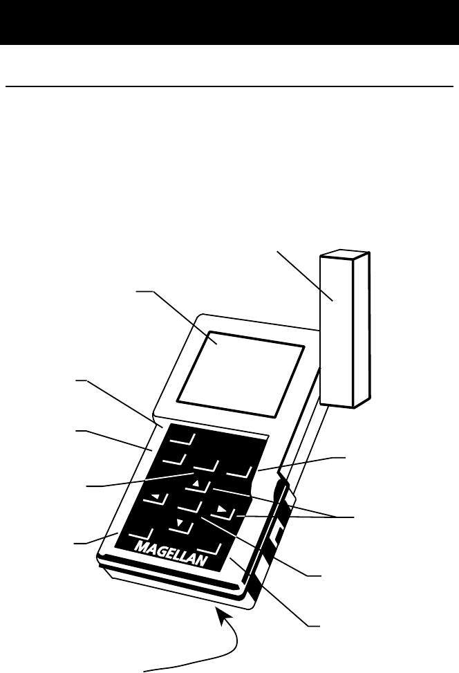
The Meridian XL is a self-contained hand-held GPS receiver designed for
general purpose position locating and navigation. It has a removable
quadrifilar antenna located on the upper right side of the receiver, a high-
contrast backlit LCD, and keypad. Using three AA batteries, inserted from
the battery door found behind and near the base of the receiver, the
Meridian XL will operate continuously for up to 6 hours.
Meridian XL
POWER
NAVPLOTMOB
GOTO
LIGHTMENU
Meridian XL
ENTER
Power Key
Turns the receiver
on and off
NAV Key
Accesses the three
navigational screens
PLOT Key
Accesses the three
graphical navigation
screens
Light Key
Turns the display
backlight on and
off
Menu Key
Accesses the
Function Menu
Enter Key
Accepts data inputs and
accesses pop-up menus
found on some screens
MOB/GOTO Key
Accesses the MOB/GOTO
list used to activate routes
Arrow Keys
Four keys used to input
data or to display other
screens.
Battery Door
(not shown)
Removable
Quadrifilar
Antenna
Backlit
Display
4
Receiver Accuracy. Before beginning, just a few words on the accuracy
of your receiver. The satellite constellation used to provide the GPS
information that your receiver uses was put into orbit and is maintained
by the Department of Defense (DoD) for use by the U.S. armed forces
and its allies. GPS positioning for general use produces an accuracy of 25
meters or better, far more accurate than anyone anticipated. Since the
signals generated by these satellites are accessible to anyone, the DoD
has introduced errors into the signals sent by the satellites for security
reasons. These errors are referred to as Selective Availability (or SA).
At present, your GPS position will be accurate to within 100 meters
horizontally and 150 meters vertically. This accuracy can be improved by
using Differential GPS (DGPS), which is described later in the manual. SA
means that 95% of the time, your horizontal coordinates will be within
100 meters of your actual position. Elevation may vary even further.
Connecting Receiver Power
Connecting Power to the Meridian XL. The Meridian XL receiver
operates on either three AA batteries or a 9-16 volt DC external power
source. Before using the Magellan Meridian XL GPS receiver, you need to
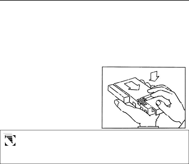
install the batteries by removing the battery compartment door as shown.
While the battery compartment was designed to be moisture resistant, it
is not sealed and will not prevent moisture from entering with prolonged
exposure. Even when operating the Meridian XL with external power, the
batteries are required to prevent loss of data if you should lose external
power for any reason.
Insert the batteries as shown in
the receiver and reinstall the
battery cover. You are now
ready to turn the receiver on.
The receiver’s memory has internal protection for power loss of
up to 10 minutes. This allows you to change the batteries
without losing the receiver’s memory provided that you change
the batteries within the 10 minute time frame.
5
First Time Use - Initializing the Receiver
You do not need to initialize your receiver each time you use it. Follow these steps
to initialize the Meridian XL if this is the first time you are using it, if the receiver
memory has been cleared or if the receiver has been transported more than 300
miles while turned off. In the latter case, you are not automatically prompted by
the receiver to reinitialize and the POSITION screen is displayed instead of the
initialization warning after the start-up screens. The POSITION screen tells you the
coordinates of the last position received. These coordinates are not necessarily
those of your current position.
Inputting Approximate Position. To give your receiver an approximate
idea of its current location, you will need to enter the approximate latitude,
longitude, date, and time of where you are now.
Since you may not know the latitude and longitude coordinates of your present
position, the Meridian XL provides you with a list of geographic regions in the
receiver’s Initialize function under Setup. This allows you to choose the general
area of the world you are in, and the specific country or province of your current
position. Selecting the appropriate location from the list will give your receiver an
approximate starting point for tracking satellites. This will greatly shorten the
time it will take the receiver to get your position for the first time (referred to as
Time To First Fix).
Turn the receiver on by holding down the POWER key until the start-up
screens appear.
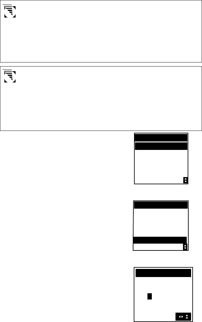
If the receiver has not been
initialized previously, or if the
receiver’s total memory has been
cleared, you will see the following
screen, prompting you to press
ENTER to initialize.
Press ENTER to Initialize.
MAGELLAN
UNIT IS NOT
INITIALIZED
PRESS ENTER
TO INITIALIZE
COPYRIGHT
MAGELLAN CORP.
BATTERY
POWER
6
If you inadvertently press another key without initializing manually, the
receiver displays the POSITION screen with null values for the latitude
and longitude (00°00.00N, 000°00.00W). In this case, the receiver will
self-initialize, which may take 15 minutes or more. The elevation mode
will automatically switch from 2D to 3D, which is necessary to obtain a
proper first fix. The recommended method is to press ENTER and
initialize manually, which will allow the receiver to get a position fix
sooner.
Using latitude and longitude will satisfy most of the users of this
receiver, but you may use any of the other coordinate systems
(UTM, OSGB, TDs, Irish Grid, Swiss Grid, Swedish Grid or Finnish
Grid) to initialize the receiver. If you prefer one of these coordi-
nate systems, select the desired coordinate system in the
COORD. SYSTEM section of Setup, then access INITIALIZE. You
will be prompted to enter the appropriate data in the format of
the chosen coordinate system.
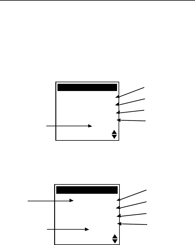
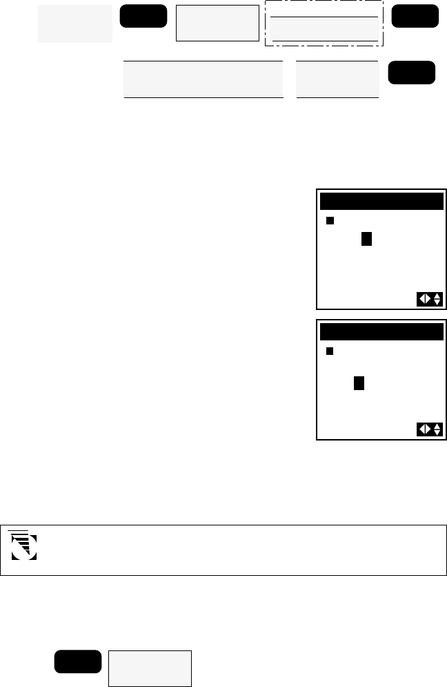
The region screen appears with a
list of locations around the globe.
This list extends to a second page
which can be viewed using the UP/
DOWN ARROWs. Highlight the
general area of the world where
you are located and press ENTER.
A list of countries, provinces or
states within that general area
appears. Use the UP/DOWN
ARROWs to select the country,
province or state of your location
and press ENTER.
The receiver displays the Initialize
page with the highlight active in
the elevation field. Use the LEFT/
RIGHT and UP/DOWN ARROWs
to enter your present elevation if
you know it, and press ENTER. If
you do not know your elevation,
simply press ENTER.
ELEVATION
37`00.00N
119`00.00W
+00000FT EL
COUNTRY/STATE
ALABAMA
ALASKA
ARIZONA
ARKANSAS
CALIFORNIA
REGION
USA
THE AMERICAS
EUROPE
EASTERN ASIA
WESTERM ASiA
7
If this is not the first time you have used your receiver, or if it is the first
time but your receiver has already begun acquiring satellite signals, the
following time and date entry may not be displayed.
Input your local time. Take extra
care to input the time correctly
(to within 10 minutes),
including the AM/PM
designator. Use the ARROW
KEYs to change the time. Use the
UP/DOWN ARROWs to change
“AM” to “PM” if necessary. When
the time is correct, press ENTER.
Please note that if you are located in a half-hour time zone, you will
need to manually reset the time, after the receiver has taken a position
fix, by adding or subtracting one half hour. Please refer to Setup - Time
Display for directions on resetting time.
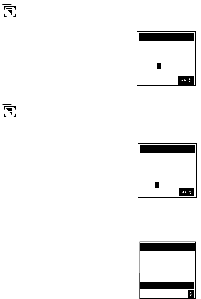
Your receiver requires just one
more piece of information and
that is the date. Use the UP/
DOWN ARROWs and RIGHT/
LEFT ARROWs to set the correct
date. Your display should resemble
the one shown at right. Double-
check all of the information
entered. Then, press ENTER.
If you notice that you made a mistake, press MNU, highlight SETUP, press
ENTER. Select INITIALIZE, press ENTER and start over.
Initializing With Known Coordinates
If you know your present latitude
and longitude, you may enter
them directly (instead of choosing
a geographic location from the
list). In this case, highlight ENTER
COORD on the second page and
press ENTER. The City Reference
Chart, found in the appendix,
provides coordinates of many
major cities.
DATE
37`00.00N
119`00.00W
+00000FT EL
12:05PM
18OCT96
TIME
37`00.00N
119`00.00W
+00000FT EL
12:05P
REGION
AUSTRALIA
AFRICA
PACIFIC
ATLANTIC
ENTER COORD
8
Press the UP ARROW. Notice that
the highlighted number has
incremented by one. Keep pressing
the UP ARROW until the first digit
matches the first number you
found for latitude. If you go past
the number you want, you can use
the DOWN ARROW to step down
or continue using the UP ARROW
and loop through the number
sequence.
When the correct number is
displayed, press the RIGHT
ARROW to step to the second digit
on the latitude line.
What’s important to remember
here is that the UP/DOWN
ARROWs step up or down through
the numbers and the RIGHT/LEFT
ARROWs move the highlight to the
right or left.
Continue entering the latitude. Use
the RIGHT ARROW to highlight
the “N” at the end of the latitude
line. Latitude may be north “N” or
south “S” and may be changed, if
necessary, by using the UP/DOWN
ARROW. Once the latitude is
correct, press ENTER.
The cursor (highlighted area) has
now jumped down to the first char-
acter on the longitude line. Follow-
ing the same procedure as before,
enter the longitude and “E” or
“W”.
Your display should now resemble the one shown above with your latitude
and longitude. If all of the information for the latitude and longitude is cor-
rect, press ENTER. (If you notice now that you made a mistake in the latitude
or longitude, press MNU, highlight SETUP MENU and press ENTER. Select
INITIALIZE, press ENTER to start over.)
0`00.00N 0
COORDINATE
000`00.00W
0
COORDINATE
3 `00.00N
000`00.00W
W
COORDINATE
34`17.00N
118`39.00
N
COORDINATE
34`17.00
000`00.00W
9
The receiver will prompt you for
your local elevation, time and date.
Use the UP/DOWN and RIGHT/
LEFT ARROWs to enter these as
described above; press ENTER to
confirm each screen.
The receiver is now ready to perform one of its primary functions,
providing you with your current position.
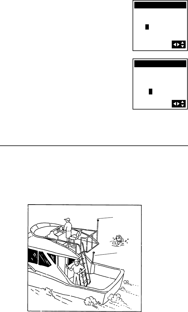
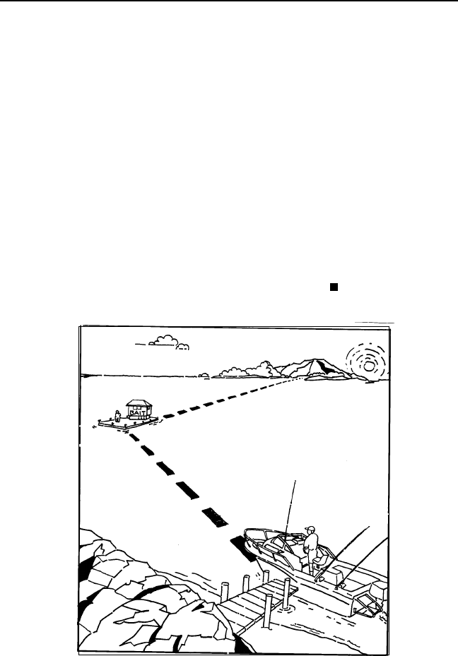
Proper Handling - Signal Reception
The illustrations show both the proper and improper placement of a fixed
antenna on a boat. Also, the fellow trying to get a position fix on the
deck of the boat would get better signals if he would move up to the
bridge. Physical obstructions (buildings, large trees, etc.) will block satellite
signals from reaching the receiver. If unable to get a position fix, move
the receiver so it has a clearer view of the sky, allowing it to choose from
all of the satellites currently available.
Good Antenna
Location
Poor Antenna
Location
+
COORDINATE
34`17.00N
118`39.00W
00000FT EL
COORDINATE
34`17.00N
118`39.00W
+00000FT EL
05:19PM
10
Taking your First Fix
To get a position fix, you must be outside with a clear view of the sky and
away from any large obstructions (buildings, large trees, etc.).
Rotate the antenna upward and hold the receiver in a comfortable position.
If the receiver is off, press the POWER key to turn the receiver on, or if
you have just finished initializing the receiver, press the NAV key until the
screen showing your coordinates is displayed. This screen is called the
POSITION screen.
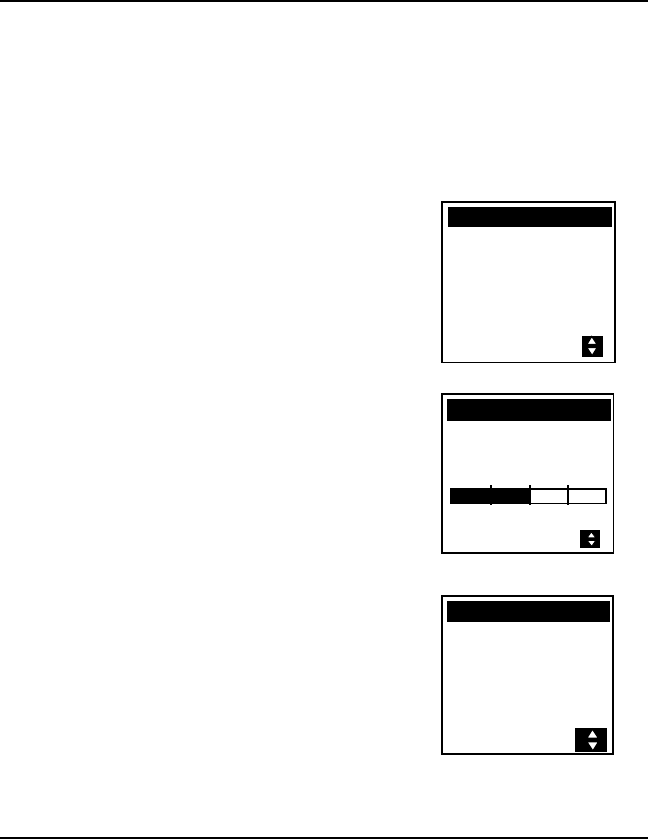
The POSITION screen appears with the
latitude, longitude, and elevation that
you entered in during INITIALIZE. The
word “SEARCHING” appears indicating
that the receiver is searching the sky
for satellites.
In a short period of time, the receiver
will locate the satellites and begin
receiving information. The first
indication of this is that “SEARCHING”
is replaced with a bar graph indicating
the receiver’s progress toward acquiring
GPS data from the satellites.
Within a few minutes, the bar graph
will disappear and be replaced with the
local time. This indicates that your
receiver is receiving GPS information
and has computed your present
position. Everything that you do from
now on is based on the position
information received.
Saving Your First Waypoint
You now have a position fix that defines your current location. During
normal operation your receiver continuously computes your position and
displays that information on the POSITION screen.
You can save this position in the receiver’s memory for use later on. This
stored fix is referred to as a waypoint. A useful way to record this would
be to assign a unique name to the position. That way, if you were to go to
a new location you could use your receiver to guide you back to your
current location.
34`17.00N
118`39.00W
0 F T E L
SEARCHING
POSITION
WGS84
34`17.00N
118`39.00W
0 F T E L
POSITION
WGS84
34`06.58N
117`49.56W
0 F T E L
10:39:07AM
POSITION
WGS84
11
Press NAV or PLOT (which will take you
to a NAV or PLOT screen if you are not
already there), then press ENTER,
highlight SAVE POS and press ENTER.
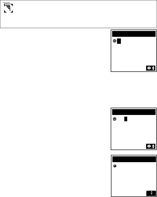
This tells the receiver that you want to
store the current position as a waypoint.
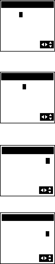
The cursor is in the upper left corner,
and the arrows displayed in the lower
right corner of the screen indicate that
it is in the edit mode. What you will do
next is assign a name to this position.
The waypoint name can be created by the receiver or you can input a
name that means something to you. If you press ENTER without creating
a name, the receiver automatically assigns a waypoint name. Waypoint
names assigned by the receiver appear in the format WPxxx, where the
xxx is a sequential number (001, 002 etc.).
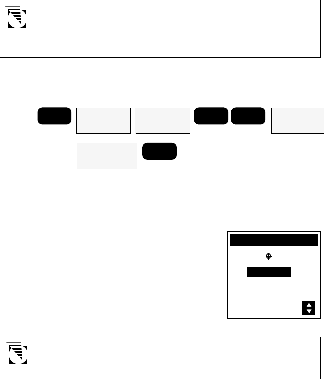
To allow the receiver to name the
waypoint automatically, press ENTER.
The following screen will appear briefly
and then the receiver returns to the
POSITION screen.
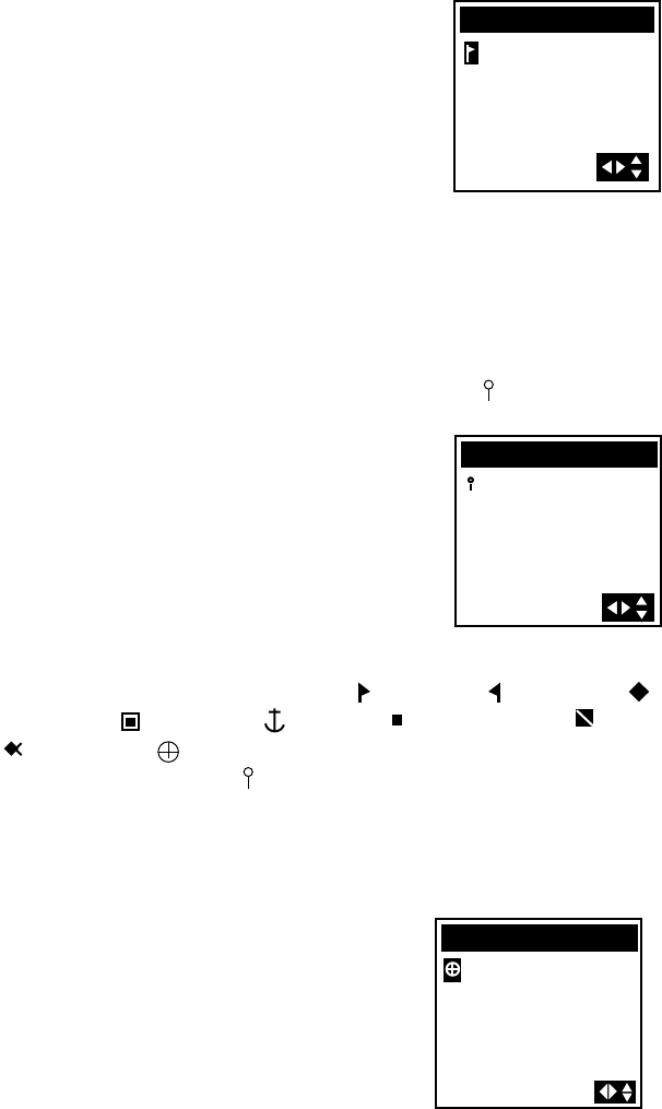
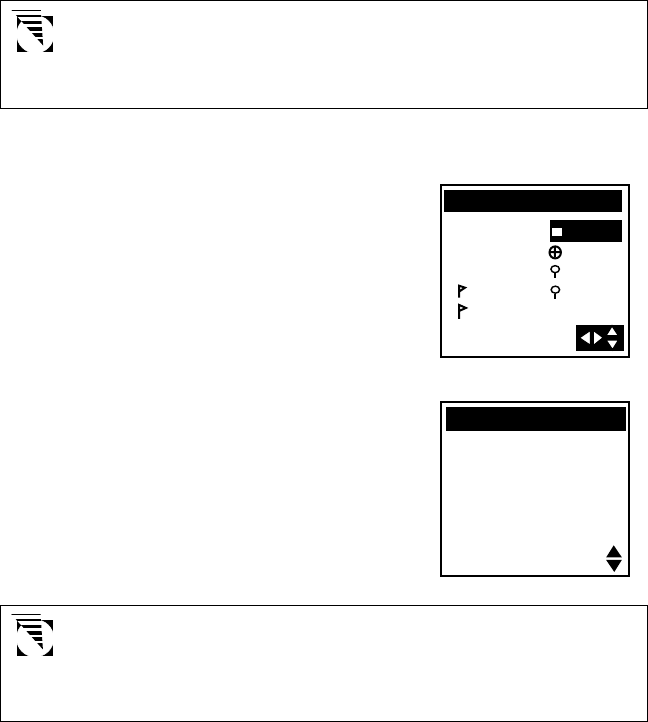
All waypoint names begin with an icon. You have the option of choosing
one of nine different icons: a right flag ( ), a left flag ( ), a diamond ( ),
a double box( ), an anchor ( ), a square ( ), a diving symbol ( ), a fish
(), or a target ( ). Unless you select a different icon, unit-generated
waypoint names use a pin ( ) icon. These icons will be used to display the
relative location of the waypoint on the PLOT screen and the ROAD screen
(described later).
Now you will save the same position as above, but this time you will
assign a name to the waypoint.
Press ENTER, highlight SAVE POS and
press ENTER again. Select an icon by
pressing the UP or DOWN ARROW .
34`06.58N
117`49.56W
0FT EL
SAVE POS
34`06.58N
117`49.56W
0 F T E L
SAVE POS
34`06.58N
A
18OCT96
117`49.56W
0 F T E L
11:56
SAVE POS
WP001
12
Selecting CREATE WPT instead of SAVE POS will allow you to
enter a waypoint exactly as described above with the additional
option of changing the latitude, longitude, and elevation of the
position. (See Creating Waypoints)
Press the RIGHT ARROW. This moves
the cursor one space to the right. Select
the letter “D” by using the UP/DOWN
ARROWs.
Press the RIGHT ARROW moving the
cursor again one character to the right.
Select the letter “O” by using the UP/
DOWN ARROWs.
A little trick in scrolling quickly through the letters and numbers in the
edit cursor is to hold down the UP or DOWN ARROW key. The characters
scroll by every third character. When you are near the character you want,
release the arrow key and step one character at a time.
Continue using the RIGHT ARROW to
move the cursor and the UP/DOWN
ARROWs until you have spelled out the
word “DOCK” and your screen appears
like the one shown. (Remember, your
position information will be different
from what is displayed here.)
Press ENTER. The screen to the right
will appear briefly and then the display
will return to the POSITION screen.
34`06.58N
117`49.56W
0FT EL
SAVE POS
D
34`06.58N
117`49.56W
0FT EL
SAVE POS
DOCK
34`06.58N
117`49.56W
0 F T E L
12:31A18OCT96
SAVE POS
DOCK
13
Introduction to Routes
A route is a planned course of travel defined by a series of waypoints. To
create a route, you select waypoints that you have stored in the receiver’s
memory. These waypoints are then connected to form the segments or
“legs” of the route. A route may contain from one to fifteen legs.
Suppose you were on a fishing trip in the area shown below. You want to
go from the dock to the bait shop, then across to the inlet on the island.
Before you start, turn the receiver on and let it get a position fix. Once
you have a fix, save it as a waypoint. That way you’ll be able to create a
route back to the dock at the end of the day, even if darkness or weather
conditions (cloud cover, rain, etc.) make it difficult to use your own
navigation skills.
In addition, you can instantly create a one-leg route called a GOTO. This
route uses your present position as its start and any waypoint you select
that you have saved in memory as the destination. The following will
show you how simple it is to create a GOTO route. In this example we
have stored a waypoint in memory and named it " JETTY."
14
If the receiver has not yet computed a position fix, then the start
of the GOTO may not represent your current position. It will,
however, correct the navigation information after a position fix is
acquired.
Creating a GOTO Route
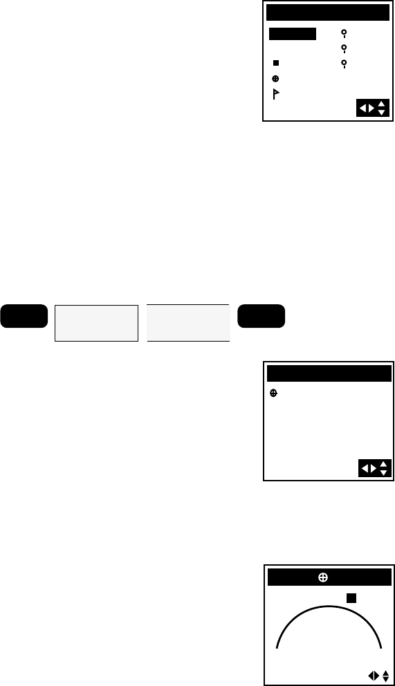
After computing a position fix, press
GOTO. Use the UP/DOWN ARROWs
to highlight the waypoint that
represents your destination.
The first four selections in the GOTO
menu allow you to create a Man
OverBoard (MOB), Backtrack, or
Coordinate route or to activate an
existing route; they are discussed in the
Reference Section.
Press ENTER. The receiver begins
navigating toward the selected
waypoint and the display returns to the
last viewed NAV screen. Note that the
destination is now placed in the header
bar of the NAV screen.
It is necessary to have a current position fix in order for the
receiver to compute navigation information. If you do not have
a position fix, the navigation information will be displayed with
dashes until a position fix is acquired.
GOTO
MOB
BCKTRK
ROUTE
COORD
JETTY
DOCK
WP001
WP002
BUOY
34`06.62N
117`49.54W
0 F T E L
09:38:15AM
POSITION
WGS84

15
Reference Section
This section explains the various functions of your receiver and is organized
by function or topic rather than by menu. To perform a given function,
refer to the Table of Contents and the Menu Cross Reference Guide in
order to quickly locate that section.
General Usage
The receiver is used to compute coordinate positions which are stored as
named waypoints and used to create routes. Waypoints can be viewed,
edited, and projected to create new waypoints, or deleted. Routes can be
created, activated, deactivated, reversed, edited and cleared. This section
covers these and other functions which will enable you to take full
advantage of your receiver’s capabilities.
Turning the Receiver On
Press the POWER key and hold for three seconds. If the batteries are
installed correctly or the external power is properly connected, the
copyright and Magellan displays will quickly flash on the screen, followed
by the POSITION screen (if the unit has been initialized) or by the message
UNIT IS NOT INITIALIZED PRESS ENTER TO INTIALIZE. (See section on
First Time Use - Initializing the Receiver.")
If these screens do not appear, please check that the battery installation
and/or external power is properly connected and turned on.
Turning the Receiver Off
To turn the receiver off, press the POWER key. The POWER DOWN
screen is displayed for five seconds. Pressing the POWER key again
before the counter reaches 1 will cause the receiver to turn off
immediately; pressing any other key will stop the receiver from turning
off.
POWER
POWER
16
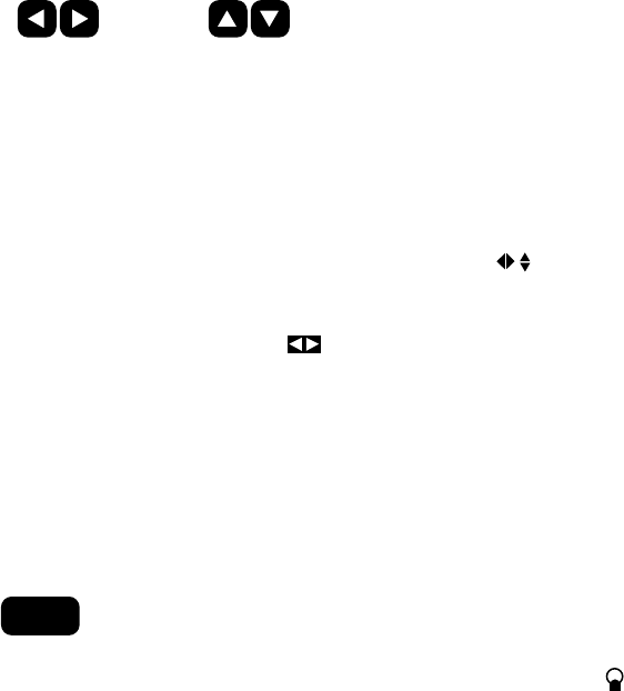
Inputting Data
Moves the cursor
one space , left or
right
Scrolls through the
icons or
alphanumeric list
The UP/DOWN and LEFT/RIGHT ARROWs have two functions depending
on how the ARROW ICONS are displayed in the bottom right corner of
the various screens.
While on some screens the UP/DOWN or LEFT/RIGHT ARROWs are used
to access additional pages, on other screens they allow you to input
data, such as waypoint names or coordinates, or to select menu items.
The ARROW ICONS in the status line indicate which mode is currently
being used. Whenever there are additional screens to view from the
one displayed, the receiver shows normal arrow icons ( ) in the lower
right corner of the display. A second type of arrow may be displayed in
the lower right hand corner. These arrows are similar to the first, but
are displayed in reverse video ( ) and are referred to as “input” or
“edit arrows.” When these reverse video arrow icons appear, the arrow
keys are used to enter data or make selections on the current display,
rather than to move from screen to screen.
Turning the Light ON and OFF
To activate the display light, press the LIGHT key. To deactivate the display
light, press the LIGHT key again.
LIGHT
The receiver will indicate that the light is on with a light bulb icon ( ) in
the status line next to the arrow icons.
The display light causes an increase in battery drain resulting in shorter
battery life.
Brightness level can be adjusted (LOW/HIGH) in the SETUP MENU.
17
NAV Screens
The three NAV screens accessible from the NAV key are the POSITION,
NAV 1 and NAV 2 screens. You may scroll through these screens using the
NAV key or the UP/DOWN ARROWs. Press NAV until the POSITION screen
is displayed.
Viewing the POSITION Screen
The POSITION screen displays the coordinates and elevation of the
current position in a larger format so that they may be easily viewed
from a distance.
POSITION Screen Using UTM Coordinate System
POSITION Screen Using LAT/LON Coordinate System
34`06.58N
117`49.56W
0 F T E L
10:39:07AM
Latitude
Longitude
Elevation
Time
POSITION
WGS84
Datum
11 423758E
3774562N
0 F T E L
10:39:07AM
Easting
Northing
Elevation
Tim e
Zone
POSITION
WGS84
Datum
18
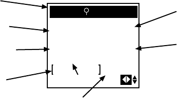
Viewing the NAV 1 Screen
Press the NAV key until the NAV 1 screen appears, showing BRG, DST,
COG and SOG. NAV 1, the first navigation screen, provides you with
information about your speed and direction of movement. If a route is
active, the NAV 1 screen also tells you where you are in relation to the
destination and courseline, and displays the name of the destination
waypoint of the active leg in the title bar.
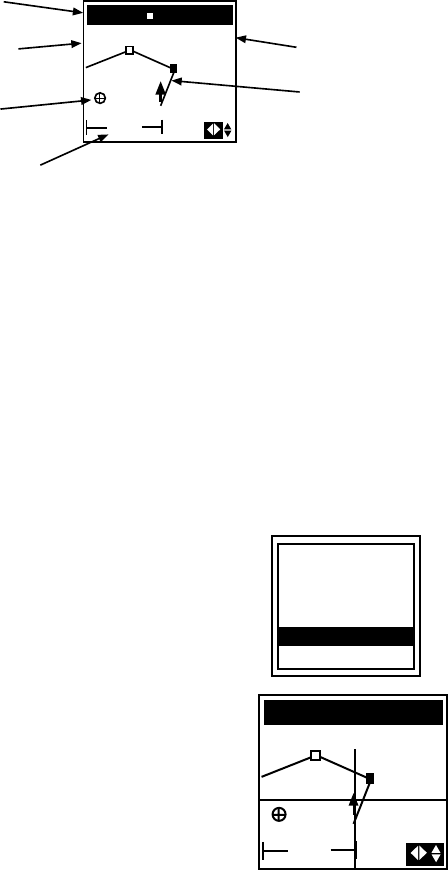
In the bottom corner of the NAV 1 screen is a CDI (course deviation
indicator), which is a graphic representation of cross track error, or how
far off course you are. The straight line is the course marker, and the
current position is represented by the arrow. If the arrow is to the left of
the course marker, you are to the left of the courseline. The number
next to the CDI is the CDI scale, or the distance from the courseline at
the center to either end of the CDI. Pressing the LEFT/RIGHT ARROWs
changes the CDI scale. Select from 0.2, 0.4, 1.0, 2.0, 4.0 or 8.0 distance
units.
BRG
... ... 1.0
n
m
Distance to
Destination
Speed Over
Ground
Course
Deviation
Indicator (CDI) CDI Scale
and Units
Bearing to
Destination
TO WP002
Current
Destination
DST
287`
M
3.87
n
m
COG SOG
282`
M
11KTS
Course Over
Ground *
* Displays dashes if receiver is stationary (<1 knot)
The default fields include bearing (BRG) to the active waypoint, Distance
(DST), course over ground (COG) and speed over ground (SOG), or
using customize, you may select VMG (velocity made good), SOA (speed
of advance), ETA (estimated time of arrival), TTG (time to go), XTE (cross
track error), STR (steering), CTS (course to steer) or a blank line. (See
Customizing the Navigation Screens.)
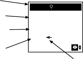
Viewing the NAV 2 Screen
Press NAV again, or use the DOWN ARROW to scroll to the NAV 2
screen.
The NAV 2 screen displays three additional information fields which
can also be customized.
19
BRG
Direction of
Cross Track
Error
Bearing to
Destination
TO WP002
Current
Destination
287`
M
COG 282`
M
XTE 0.04
n
m
Course Over
Ground *
Cross Track
Error
* Displays dashes if receiver is stationary (<1 knot)
Information is displayed in a large format so that it may be easily viewed
from a distance. All of the fields can be customized; default fields include
bearing (BRG) to the active waypoint, course over ground (COG) and
cross track error (XTE), or you may select VMG (velocity made good),
SOA (speed of advance), SOG (speed over ground), ETA (estimated time
of arrival), TTG (time to go), DST (distance), XTE (cross track error), STR
(steering), CTS (course to steer) or a blank line. Cross track error (XTE) is
displayed as a numeric value. The arrow next to XTE indicates the
direction of the error, left or right of the course line.
Customizing the Nav Screens
As previously mentioned, NAV 1 and NAV 2 screens can be customized
to display the data fields you find most convenient for navigation.
When you access these two screens for the first time, the fields shown
are the default choices. The NAV 1 screen displays BRG, DST, COG and
SOG fields, while the NAV2 screen displays BRG, COG and XTE fields.
Available options include:
BRG Bearing to the active waypoint
DST Distance to the active waypoint
SOG Speed Over Ground
COG Course Over Ground
ETA Estimated time of arrival to the active waypoint
TTG Time to go
VMG Velocity made good toward active waypoint
XTE Cross track error
SOA Speed of Advance toward active waypoint
CTS Course to steer
STR Steering

20
Press the NAV key from any screen to view a NAV screen. Press NAV
again as necessary to display either the NAV 1 or NAV 2 screen.
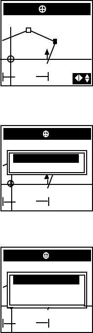
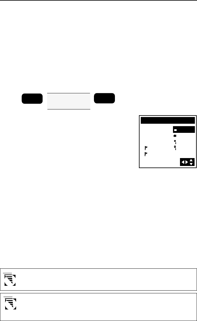
Press ENTER to display the pop-up
menu.
Use the UP/DOWN ARROWs to
highlight CUSTOMIZE and press
ENTER.
The pop-up menu disappears and the
display returns to the NAV screen from
which you came.
NAV 1 screen
When the pop-up menu disappears and the display returns to the NAV
1 screen, the first field is highlighted. (The first default is BRG, but
another option may appear if you have previously customized the fields.)
Use the UP/DOWN ARROWs to select the field to edit, and the LEFT/
RIGHT ARROWs to scroll through the various options.
After you have selected an option, press the UP/DOWN ARROWs to
move to the next field, where you scroll through the list of options
again using the LEFT/RIGHT ARROWs.
When you have finished selecting all of the options you wish to include
in the NAV 1 screen display, press ENTER to exit and save the selections.
NAV 2 screen
When the pop-up menu disappears and the display returns to the
NAV 2 screen, the first default field heading “BRG” is highlighted.
Use the UP/DOWN ARROWs to select the field to edit, and the LEFT/
RIGHT ARROWs to scroll through the various options.
After you have selected an option, press the UP/DOWN ARROWs to
move to the next field, where you scroll through the list of options
again using the LEFT/RIGHT ARROWs.
When you have finished selecting all of the options you wish to include
in the NAV 2 screen display, press ENTER to exit and save the selections.
SAVE POS
CREATE WPT
ROUTE MENU
CONTRAST
CUSTOMIZE
ESCAPE
21
PLOT SCREENS
Three graphical screens can be accessed from the PLOT key: the PLOT
screen, the ROAD screen and the POINTER screen. You may scroll through
these three screens by pressing the PLOT key repeatedly once you have
accessed one of the PLOT screens or by using the UP/DOWN ARROWs.
Press ENTER from any of these three screens to display the pop-up menu.
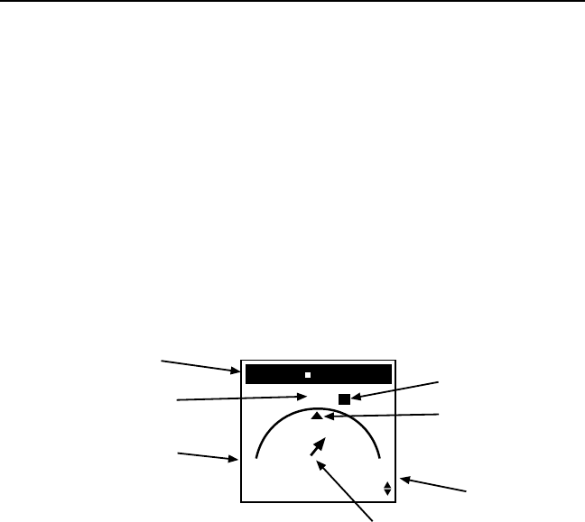
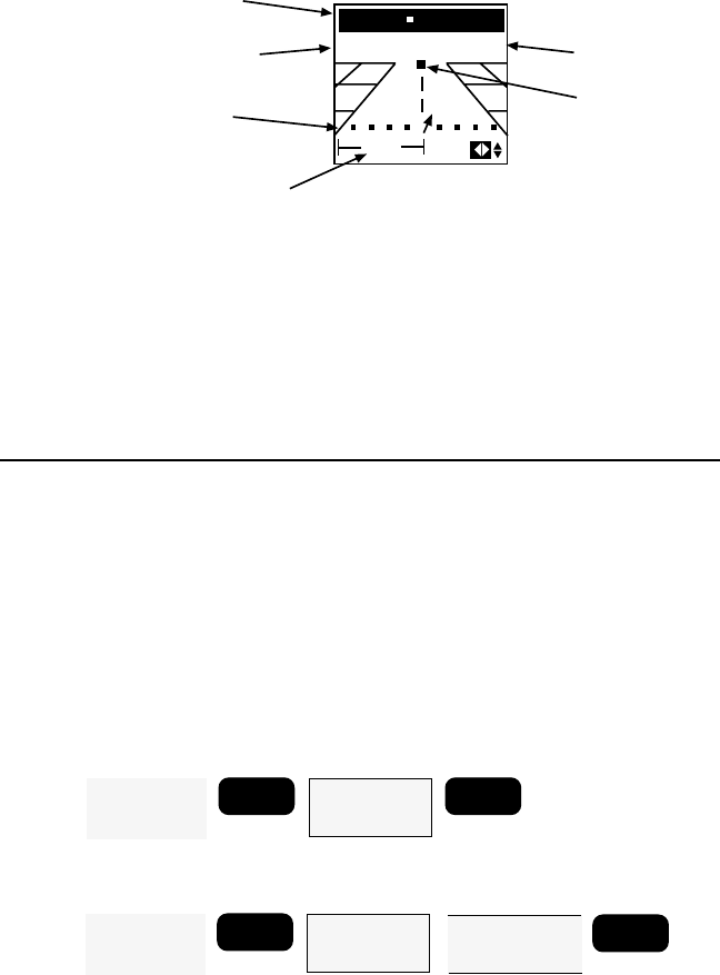
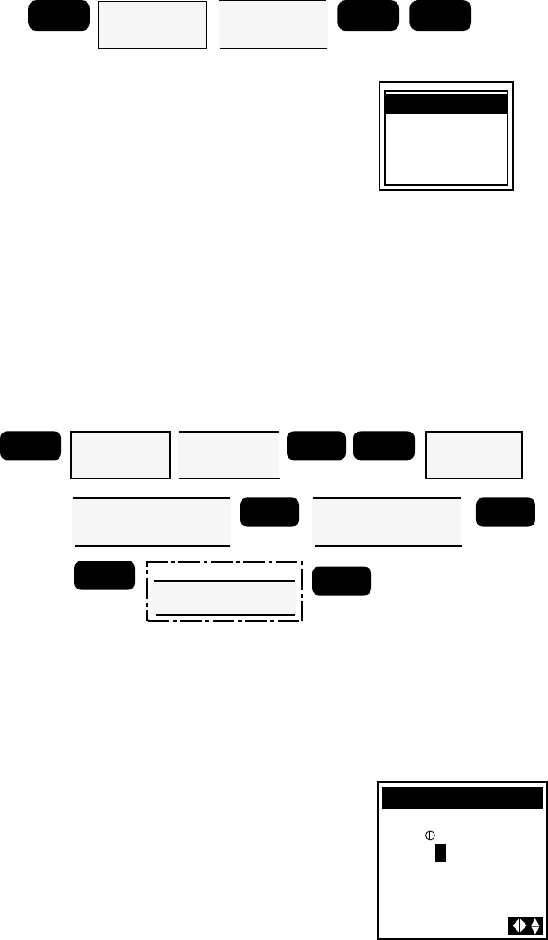
Viewing the POINTER screen
Access the POINTER screen by pressing the PLOT key (twice or three
times, if necessary). This screen graphically displays the TO destination
waypoint of the current leg if there is an active route or GOTO and
the bearing and distance to that waypoint. An arrow inside the arc
points toward the destination of the active leg, shown as a waypoint
icon.
028` n
m
TO JETTY
N
E
BRG DST
M
13.5
Current
Destination
Bearing to
Destination Distance to
Destination
Destination
Icon **
Direction
Designator COG
Indicator *
Bearing
Indicator *
* Displayed only if receiver is moving
** The destination icon disappears if it
extends past the displayed arc (is
behind you).
Viewing the PLOT Screen
This screen plots your route on the display using the arrow icon to
display your relative position on the route. Your track is also displayed,
allowing you to follow your movement in relation to the course.
Press the PLOT key as necessary to access the PLOT screen. If many of
the waypoints you have created are contained in the current display
range, the screen may take several seconds to redraw. (If the screen
does not look similar to the one shown on the following page after
several seconds, press the PLOT key repeatedly to scroll though the
sequence.)
22
The PLOT screen displays “TO destination waypoint” of the current leg
if there is an active route or GOTO, and the bearing and distance to
that waypoint.
Changing the Plotter Scale
Press the LEFT/RIGHT ARROWS to adjust the scale, shown at the
bottom left corner of the screen.
Using PAN N SCAN
The PLOT screen is equipped with a PAN N SCAN feature that allows
the user to access waypoint information by positioning the cursor over
the waypoint. (To access the PLOT screen you may need to press the
PLOT key several times to scroll through the sequence.)
From the PLOT screen, press ENTER to access the pop-up menu. You
will notice that this menu is different from the pop-up menu accessed
from other screens in that it has an additional feature, PAN N SCAN.
Using the UP/DOWN ARROWs,
highlight PAN N SCAN and press
ENTER.
n
m
PAN N SCAN
BRG DST 13.5
028`
M
25
n
m
The PAN N SCAN screen is similar to
the PLOT screen, however a vertical and
horizontal line cross to form a cursor.
The bearing (BRG) and distance (DST)
from your present position to the cursor
are displayed at the top of the screen.
Use the UP/DOWN and LEFT/RIGHT
ARROWs to move the cursor anywhere
on the screen or to scroll off the screen
to view portions of the active route not
currently shown on the screen.
n
m
TO JETTY
BRG DST 13.5
Current
Destination
Bearing to
Destination
Distance to
Destination
Scale
028`
M
25
n
m
Near
Waypoint
Icon
Intended
Course
SAVE POS
CREATE WPT
ROUTE MENU
CONTRAST
PAN N SCAN
ESCAPE
23
When the cursor covers a waypoint icon
on the screen, the title bar displays the
name of that waypoint and, just below,
the bearing and distance to the
waypoint.
n
m
TO BUOY
BRG DST 23.5
256`
M
25
n
m
Setting a GOTO Using PAN N SCAN
When the cursor is on an icon and the waypoint name is displayed,
press ENTER.
A GOTO confirmation screen appears
with options GOTO and ESCAPE. Select
GOTO and press ENTER to return to
the PLOT screen or ESCAPE and press
ENTER to return to the PAN N SCAN
screen.
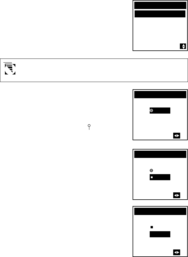
When the cursor on the PAN N SCAN screen is not on an icon, a GOTO
can be created to the coordinates at the cursor location. Press ENTER.
A GOTO confirmation screen appears
with options CREATE WPT, GOTO and
ESCAPE. Select GOTO and press ENTER
to create a one-leg route to the
coordinates at the cursor position and
return to the PLOT screen.
If no waypoint currently exists at the cursor position and you wish to
create one while creating a GOTO, select CREATE WPT and press ENTER.
Use the UP/DOWN and RIGHT/LEFT ARROWs to assign a name to
the waypoint and press ENTER.
To exit the PAN N SCAN screen, press ENTER when no waypoint is
covered by the cursor. The display returns to the PLOT screen.
Deleting Plotter Track
As you use your receiver more, you may soon notice the PLOT screen
becoming cluttered with the graphic display of your past movement
(track). You can erase the track display with the DELETE TRACK option
in the Clear Menu. Press MENU and use the UP/DOWN ARROWs to
highlight CLEAR MENU. Press ENTER and use the UP/DOWN ARROWs
to highlight DELETE TRACK and press ENTER. You will be asked to
confirm that you want to delete the track history. If you change your
mind, press any other function key to leave the track as it is.
n
m
TO BUOY
BRG DST 23.5256`
M
25 n
m
CREATE WPT
GOTO
ESCAPE
n
m
TO BUOY
BRG DST 23.5256`
M
25 n
m
GOTO
ESCAPE
24
Viewing the ROAD Screen
Access the ROAD screen by pressing the PLOT key (two or three times,
if necessary). This is the navigation CDI screen. As with the preceding
screen, the bearing and distance to the leg destination are displayed.
n
m
TO JETTY
BRG DST 13.5028`
M
25
n
m
Scale
Current
Destination
Bearing to
Destination
Distance to
Destination
Destination
Icon
Course
Deviation
Indicator
This screen depicts the course you should be on as the center line and
your position relative to the course (the arrow icon). Any waypoints
that would appear on or near this courseline are displayed as they come
into range.
When a route is active, you can adjust the CDI scale by pressing the
LEFT/RIGHT ARROWs shown in the bottom left corner of the screen.
WAYPOINTS
Saving a Position Fix as a Waypoint
During normal operation your receiver continuously computes your
position and displays that information on the POSITION screen. Quite
often you will want to store the position data for use later on. This
stored fix is referred to as a waypoint. An obvious use would be to store
the position where you are now with a unique name. That way if you
were to go to a new location you could use your receiver to guide you
back to your current location.
Receiver Generated Waypoint Name
ENTER
From any
NAV or PLOT
Screen
Highlight
SAVE POS
Press ENTER
ENTER
User Defined Waypoint Name
ENTER
From any
NAV or PLOT
Screen
Highlight
SAVE POS
Press ENTER
ENTER
Use ARROW
KEYS to assign
icon and name
25
From any NAV or PLOT screen, press
ENTER, highlight SAVE POS and press
ENTER. This tells the receiver that you
want to store the current position as a
waypoint. The cursor is in the upper left
corner of the display and the
highlighted arrow icons indicate that it
is in the edit mode. What you will do
next is assign a name to this position.
The waypoint name can be created by the receiver or you can input a
name that means something to you. If you press ENTER without creating
a name the receiver assigns a waypoint name. Waypoint names assigned
by the receiver appear in the format WPxxx, where the xxx is a
sequential number (001, 002, etc.).
To allow the receiver to name the
waypoint, press ENTER. The following
screen will appear briefly and then the
receiver returns to the POSITION screen.
or
Use the ARROWs to assign a waypoint
name that describes the position being
saved. A waypoint name always starts
with an identifier icon and 1 to 5
characters. After assigning a name,
press ENTER. The following screen will
appear briefly and then the receiver
returns to the POSITION screen.
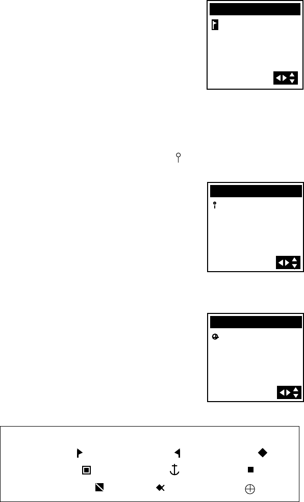
Available Icons:
Right flag ( ) Left flag ( ) Diamond ( )
Double box( ) Anchor ( ), Square ( )
Diving symbol ( ) Fish ( ) Target ( )
34`06.58N
A
18OCT96
117`49.56W
0 F T E L
11:56
SAVE POS
WP001
34`06.58N
117`49.56W
0 F T E L
12:31A18OCT96
SAVE POS
DOCK
34`06.58N
117`49.56W
0 F T E L
SAVE POS
26
Creating a Waypoints
This allows you to create and store a waypoint with a receiver-generated
name or a user-assigned name and allows you to assign the position
coordinates.
From any NAV or PLOT screen, press ENTER, highlight CREATE WPT
and press ENTER. The CREATE WPT screen appears.
Press ENTER to accept a receiver-generated name or use the ARROWs
to assign a name of your choice and press ENTER.
The cursor moves to the first line of the
position. Use the UP/DOWN
ARROWs to scroll through the number
list, and use the LEFT/RIGHT ARROWs
to move the cursor. If using LAT/LON
coordinate system, the UP/DOWN
ARROW toggles between N and S.
Press ENTER to confirm and continue.
Using the LEFT/RIGHT and UP/DOWN
ARROWs you can change the second
line of the position. If using LAT/LON
coordinate system , the UP/DOWN
ARROW toggles between E and W.
Press ENTER to save the changes.
CREATE POS
JETTY
34`06.58N
117`49.56W
0FT EL
CREATE POS
JETTY
34`12.45N
117`49.56W
0FT EL
You may now assign the elevation. If you do not know the elevation,
press ENTER to accept the displayed value. In a few seconds the new
waypoint is saved and the receiver returns to the NAV screen from
which you started.
You can also create waypoints from the waypoint menu by
selecting CREATE and proceeding as described above.
Accessing the Waypoint Menu
The Waypoint Menu contains up to 200 named waypoints, displayed
in two columns of four waypoints each and extending to several pages.
MENU Highlight
WAYPOINTS
Press ENTER
Use ARROW KEYS to
assign icon and name
ENTER
From any
NAV or PLOT
Screen
Highlight
CREATE WPT
Press ENTER
ENTER
optional:
Use ARROW KEYS to assign
position coordinates. Press
ENTER to move to the next line.
Use ARROW
KEYS to assign
elevation value.
ENTER
27
To access the Waypoint Menu, press
MENU. Use the UP/DOWN ARROWs
to select WAYPOINTS and press ENTER.
This will take you to the WPT MENU
screen. This is a listing of all the
waypoints you have stored in your
receiver.
As the number of waypoints in the library increases, the WPT MENU
screen will add a second column of four waypoint names to the right of
the ones you have now, and will continue to another “page.” Use the
LEFT/RIGHT ARROWs move from column to column and the UP/
DOWN ARROWs move up and down through the list. When you reach
the end of the page, the cursor will automatically scroll to the next
page.
Viewing a Waypoint
MENU Highlight
WAYPOINTS
Press ENTER
Use ARROW
KEYS to select
waypoint
ENTER
From the WPT MENU, use the UP/
DOWN and LEFT/RIGHT ARROWs to
highlight the waypoint you wish to view
and press ENTER to display the
WAYPOINT screen. This screen closely
resembles the POSITION screen with the
notable addition of the time and date
the waypoint was saved.
Use the LEFT or RIGHT ARROWs to display the WAYPOINT screen
for adjacent waypoints in the waypoint list. Continue pressing the
LEFT or RIGHT ARROW to scroll through the entire list.
The UP/DOWN ARROWs give the
bearing (BRG) and distance (DST) for
the selected waypoint on the POINTER
screen.
028`
n
m
TO DOCK
N
E
BRG DST
M13.5
34`06.58N
117`49.56W
0 F T E L
12:31A18OCT96
WAYPOINT
DOCK
WPT MENU
JETTY
POS
DOCK
BUOY
WP001
WP002
WP003
CREATE
28
Accessing the Waypoint Function Menu
MENU Highlight
WAYPOINTS
Press ENTER
Use ARROW
KEYS to select
waypoint
ENTER ENTER
Press MENU, use the UP/DOWN
ARROWs to select WAYPOINTS and
press ENTER. Select a waypoint from
the list and press ENTER to access the
WAYPOINT screen, press ENTER again
to access a menu of functions that may
be performed on the selected
waypoint.
The ESCAPE option allows you return to the WAYPOINT screen by
pressing ENTER when ESCAPE is highlighted.
Projecting a Waypoint
This function allows you to project a waypoint, which means to create
a waypoint at a certain distance and bearing from an existing waypoint.
Press MENU, use the UP/DOWN ARROWs to select WAYPOINTS
and press ENTER. Select the waypoint in the list from which you wish
to project a new waypoint, then press ENTER to access the WAYPOINT
screen. Now press ENTER to access the function menu, highlight
PROJECT and press ENTER.
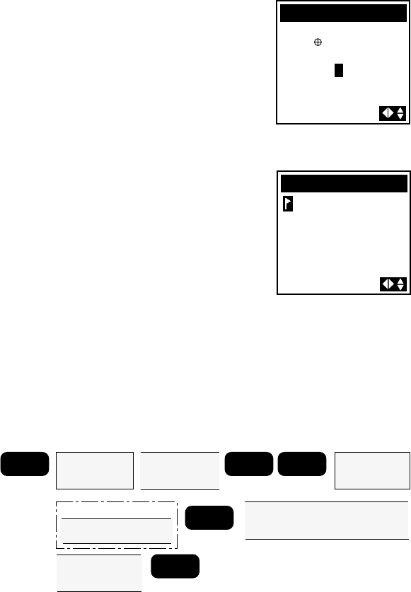
The WPT PROJECT screen appears with
the cursor positioned on the first
character in the distance field (DIST).
WPT PROJECT
FROM DOCK
DIST 000.0
BRG
n
m
ESCAPE
EDIT
WPT PROJEC
SUNRISE
DELETE
MENU Highlight
WAYPOINTS
Press ENTER
Use ARROW
KEYS to select
waypoint
ENTER ENTER Highlight
WPT PROJEC
Press ENTER
Use ARROW KEYS to
assign distance from
chosen waypoint
ENTER Use ARROW KEYS to
assign bearing from
chosen waypoint
ENTER
ENTER Use ARROW KEYS to
assign icon and name
ENTER
optional:
29
Use the UP/DOWN and LEFT/RIGHT ARROWs to key in the distance
at which you wish to project the new waypoint. When you have
finished, press ENTER to confirm and continue.
The cursor appears in the bearing field
(BRG). Use the UP/DOWN and LEFT/
RIGHT ARROWs to key in the bearing
at which you wish to project the new
waypoint. When you have finished,
press ENTER to confirm.
The coordinates of the projected
waypoint you have just created appear
on the WPT PROJECT screen.
To save these coordinates as a
waypoint, press ENTER to access the
DEFINE WPT screen, assign a name
using the UP/DOWN and LEFT/RIGHT
ARROWs, then press ENTER.
WPT PROJECT
FROM DOCK
DIST 045.0
BRG 010`
n
m
M
34`47.69N
117`27.38W
0FT EL
DEFINE WPT
The projected waypoint is saved as a new waypoint and the display
returns to the WAYPOINT screen from which you projected the new
waypoint.
Editing a Waypoint
This enables you to rename a waypoint (optional) and to change the
coordinate values for the waypoint.
Press MENU, use the UP/DOWN ARROWs to select WAYPOINTS
and press ENTER. Select a waypoint from the list and press ENTER to
access the WAYPOINT screen. Press ENTER to access the function
menu, highlight EDIT and press ENTER.
MENU
Highlight
WAYPOINTS
Press ENTER
Use ARROW
KEYS to select
waypoint
ENTER ENTER
Highlight
EDIT
Press ENTER
Use ARROW KEYS to
rename waypoint
ENTER
optional: Use ARROW KEYS to change
position coordinates. Press
ENTER to move to the next line.
Use ARROW
KEYS to change
elevation value.
ENTER
30
Waypoints that are currently used in a route (discussed in the
next section) cannot be cleared. The receiver will warn you if you
attempt to do so.
Changing the name of the waypoint is the first option. Use the LEFT/
RIGHT ARROWs to move the cursor and the UP/DOWN ARROW
to select the characters. After changing the waypoint name or if
there are no changes to the waypoint name, press ENTER.
Make a changes to the position using the UP/DOWN ARROWs to
scroll through the number list, and use the LEFT/RIGHT ARROWs to
move left and right. Press ENTER to accept the changes. After all
changes are made to the position and elevation, press ENTER. In a
few seconds the changes will be saved and the receiver returns you
to the WAYPOINT screen of the edited waypoint. Any name changes
that you made under edit have been saved, replacing the former
name and/or coordinates.
If you attempt to edit a waypoint contained in a route, a warn-
ing message will appear: "WARNING - WPT USED IN ROUTE
ENTER TO CONTINUE." You must first delete the waypoint from
the route (or delete the route) before modifying the waypoint.
Deleting a Waypoint
Used to permanently remove a waypoint from your receiver’s memory.
MENU
Highlight
WAYPOINTS
Press ENTER
Use ARROW
KEYS to select
waypoint
ENTER ENTER
Highlight
DELETE
Press ENTER
Highlight YES to
confirm deletion
ENTER
Press MENU, use the UP/DOWN ARROWs to select WAYPOINTS
and press ENTER. Select the waypoint in the list you wish to delete,
then press ENTER to access the WAYPOINT screen. Now press ENTER
to access the function menu, highlight DELETE and press ENTER.
The receiver will now give you one last
chance to change your mind. If you are
sure, use the UP/DOWN ARROWs to
highlight YES and press ENTER. The
waypoint is now erased and you are re-
turned to the next waypoint in the list.
WARNING
NO
YES
DELETE DOCK
31
ROUTES
A route is a planned course of travel defined by a series of waypoints. To
create a route, you must already have waypoints stored in the receiver’s
memory. These waypoints are then connected to form the segments or
“legs” of the route. A route may contain from one to fifteen legs.
Activating a GOTO Route
The GOTO function enables you to create a simple one-leg route from
your present position to a defined waypoint. When a GOTO is active,
the title bar of the NAV and PLOT screens display “TO Destination
Waypoint” and the screens display the corresponding navigation
information.
GOTO
Use ARROW KEYS
to select
destination waypoint
ENTER
Press GOTO, use the UP/DOWN
ARROWs to highlight the desired
destination waypoint, and press
ENTER.
The first four selections in the GOTO menu allow you to create a Man
OverBoard, Backtrack or Coordinate route or to activate an existing
route. MOB, BCKTRK and COORD functions are discussed at the end of
the Route section.
It is also possible to activate a GOTO from the PAN N SCAN feature on
the PLOT screen as described earlier.
The receiver begins navigating toward the selected waypoint and the
display returns to the last viewed NAV screen.
It is necessary to have a current position fix in order to correctly activate
a GOTO. If you have a current position fix, the NAV screens will display
navigation data, if not, the navigation data will be replaced by dashes.
If a route, GOTO, or MOB is already active, the new GOTO
automatically replaces it and becomes the active route.
A GOTO always uses your current position as the starting point.
If the unit has not yet computed a position fix, then the start of
the GOTO may not represent your current position.
GOTO
MOB
BCKTRK
ROUTE
COORD
JETTY
FISH
WP001
WP002
BUOY
32
Accessing the Route Menu
The Route Menu is used to create and view up to five single or multi-
leg routes. A pop-up menu allows you to activate, deactivate, or reverse
a selected route, edit or view the legs of the route, or clear the route.
The ROUTE MENU can be accessed in three ways:
Press MENU, use the UP/DOWN
ARROWs to select ROUTE MENU in the
FUNCTION MENU, and press ENTER.
FUNCTION MENU
SAT STATUS
ROUTE MENU
WAYPOINTS
SETUP
SIMULATOR
From any NAV or PLOT screen,
press ENTER to access the pop-up
menu, select ROUTE MENU and press
ENTER.
Press GOTO and highlight ROUTE
and press ENTER.
Creating a Multileg Route
This creates a route of 1 to 15 legs. Each leg has a start and end
waypoint. Each end waypoint is the start waypoint for the following
leg.
Access the
ROUTE
MENU
Use ARROW KEYS
to highlight an empty
route
ENTER
Use ARROW KEYS
select start of route
waypoint
ENTER
Use ARROW KEYS
select end of leg
waypoint
ENTER
To finish creating a multileg route, press ENTER without selecting
a "TO" waypoint.
SAVE POS
CREATE WPT
ROUTE MENU
CONTRAST
ESCAPE
GOTO
MOB
BCKTRK
ROUTE
COORD
JETTY
DOCK
WP001
WP002
BUOY
33
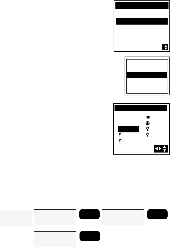
Access the ROUTE MENU. Use the UP/
DOWN ARROWs to select an EMPTY
route and press ENTER.
ROUTE MENU
1 EMPTY
2 EMPTY
3 EMPTY
4 EMPTY
5 EMPTY
If there are no EMPTY routes in the ROUTE MENU, you must
clear a route before you can create a new one.
Use the LEFT/RIGHT ARROWs to
select the FROM waypoint and press
ENTER. This is the starting position for
this leg of your route. The default
waypoint in the FROM field is the
current position, labeled as STRT1. The
“1” indicates that it is the START
waypoint of Route 1.
The highlight moves down to the TO
line. Use the LEFT/RIGHT ARROWs to
change the TO waypoint to be the
destination for this leg. Note that the
screen displays the bearing and distance
for this leg of the route. Press ENTER
to confirm the TO waypoint.
SET ROUTE
LEG 01
FROM DOCK
TO
SET ROUTE
LEG 01
FROM DOCK
TO JETTY
028` 13.5
n
m
M
SET ROUTE
LEG 02
FROM JETTY
TO
The receiver automatically used the TO
waypoint from the previous leg as the
FROM waypoint for the next leg.
Continue to add legs to this route by using the LEFT/RIGHT ARROWs
changing the TO waypoint and ENTER to confirm. The bearing and
distance are updated as you scroll through the various TO waypoints.
When you have created as many legs of the route as desired, simply
press ENTER with the TO highlight blank.
34
The display returns to the Route Menu. The new route is now the active
route, and can be viewed on the NAV and PLOT screens.
The receiver will not accept TO waypoints having the same or
nearly the same coordinates (within 0.1 distance units) as the
FROM waypoint.
Activating and Deactivating a Route
Only one route, MOB, BACKTRACK, COORD route or GOTO can be
active (in use) at any time. When you set a MOB, GOTO or BACKTRACK
route, any multileg route that you were using is automatically deactivated
and replaced with the route you just set. Likewise, creating a multileg
route makes that route the current active route, deactivating any other
route.
Access the
ROUTE
MENU
Use ARROW KEYS
to highlight route to
activate / deactivate
ENTER ENTER
Access the ROUTE MENU and use the UP/DOWN ARROWs to
highlight the route you wish to activate or deactivate and press ENTER
to display the pop-up menu.
Use the UP/DOWN ARROWs to highlight ACTIVATE or DEACTIVATE
and press ENTER.
If the route you selected is currently active, DEACTIVATE will appear on
the menu, and pressing ENTER will deactivate the route. If the route is
not active, ACTIVATE will appear on the menu, and pressing ENTER will
activate the route and return you to the last viewed NAV screen.
Reversing a Route
REVERSE ROUTE allows you to take an existing route and reverse the
order of waypoints in the route. For example, if you were to set a route
that went from point A to point B and ended at point C, REVERSE
ROUTE would change the route to go from point C to point B and
ending at point A.
Access the
ROUTE
MENU
Use ARROW KEYS
to highlight route to
be reversed
ENTER
Highlight
REVERSE
Press ENTER
Access the ROUTE MENU, highlight the route you want to reverse,
and press ENTER. Use the UP/DOWN ARROWs to highlight REVERSE
and press ENTER.
The route is reversed and the display returns to the ROUTE MENU.
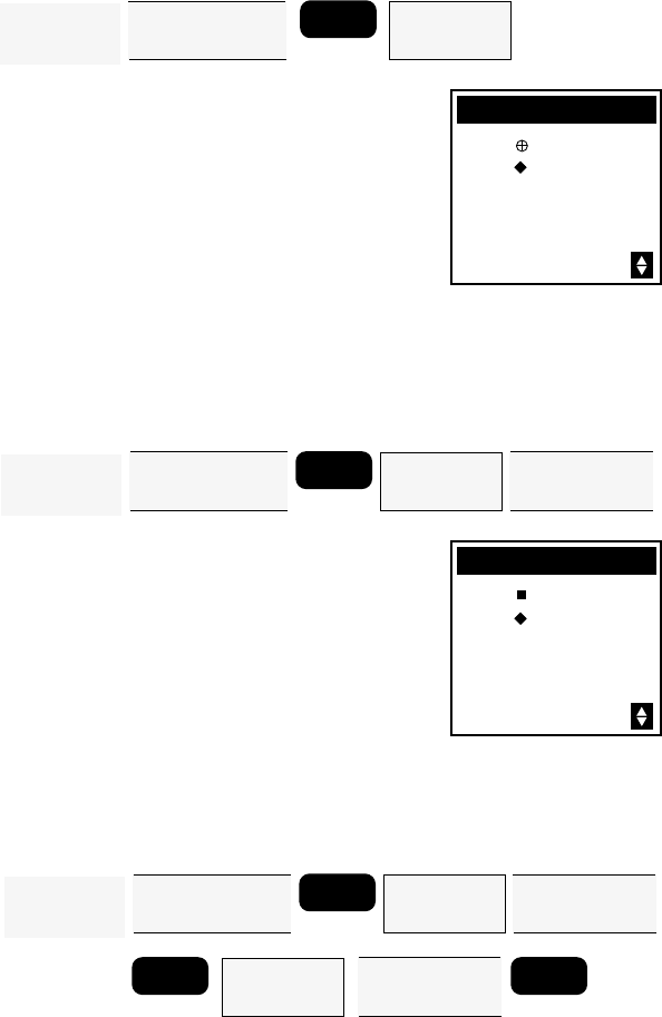
35
Viewing the Route Summary (Edit Option)
The edit option displays a summary of the selected route, including
starting and ending waypoints, number of legs, and total distance. It
allows you to view, insert, delete and replace individual legs of a route,
as well as choose the leg on which you want to navigate by making this
the current active leg.
Access the
ROUTE
MENU
Use ARROW KEYS
to highlight route to
be edited
ENTER Highlight
EDIT
Press ENTER
Access the ROUTE MENU. Use the UP/
DOWN ARROWs to highlight the
route you want to view and press
ENTER. Use the UP/DOWN ARROWs
to highlight EDIT and press ENTER.
The SUMMARY screen for the selected
route is displayed.
SUMMARY
FROM DOCK
TO FISH
2 LEGS
TOTAL 28.3
DIST
n
m
Viewing the Legs of a Route
The legs of a route can be viewed individually by accesing the EDIT
option. Thist is also the option from which legs can be added, inserted,
removed, navigated or replaced.
Access the
ROUTE
MENU
Use ARROW KEYS
to highlight route to
be edited
ENTER Highlight
EDIT
Press ENTER
Use UP/DOWN
ARROWs to view
route legs
To review the route by viewing each of
the legs individually, starting from the
SUMMARY screen, press the UP/
DOWN ARROWs stepping through
each leg of the route and back to the
route summary.
LEG 2
FROM JETTY
TO FISH
223` 14.8
n
m
M
BRG DST
Inserting a Leg in a Route
You can insert a leg in a route by inserting a waypoint between the
starting and ending waypoints of an existing leg, thereby dividing it
into two legs.
Access the
ROUTE
MENU
Use ARROW KEYS
to highlight route to
be edited
ENTER Highlight
EDIT
Press ENTER
Use UP/DOWN
ARROWs to select
route leg
ENTER Highlight
INSERT
Press ENTER
Use LEFT/RIGHT
ARROWs to select
"TO" waypoint
ENTER
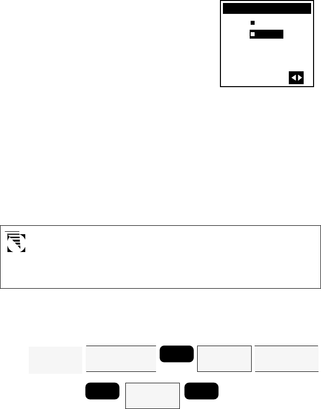
36
Access the ROUTE MENU and highlight the route to insert a leg into.
Press ENTER to bring up the pop-up menu, highlight EDIT, and press
ENTER. Use the UP/DOWN ARROWs to view the route leg in which
you want to insert a waypoint, press ENTER to access the EDIT LEG
menu, select INSERT, and press ENTER.
A highlight bar appears for you to select
the new TO waypoint for this leg,
thereby creating a new waypoint and
“pushing” the other waypoints in the
route forward to make room.
Use the LEFT/RIGHT ARROWs to scroll
through the waypoint list to the
waypoint you wish to use as the
destination for this new intermediate
leg and press ENTER.
The new leg has now been added. The FROM waypoint did not change
but the TO waypoint is now the one you just entered. The receiver
has updated the bearing and distance for this leg and displays it on
the screen.
Press the DOWN ARROW. The following leg has also been changed.
The following leg now starts from the waypoint you designated as
the TO waypoint for the previous leg.
The new TO waypoint must be different from the old (must have
a distance greater than 0.1 distance units from the "FROM"
waypoint); the receiver will not insert a leg in this case but will
return to the leg screen you were viewing.
Deleting a Leg
Another feature of editing a route is the ability to delete one of the
legs.
Access the
ROUTE
MENU
Use ARROW KEYS
to highlight route to
be edited
ENTER Highlight
EDIT
Press ENTER
Use UP/DOWN
ARROWs to select
route leg
ENTER Highlight
DELETE
Press ENTER
ENTER
Access the ROUTE MENU and highlight the route to be edited. Press
ENTER, highlight EDIT, and press ENTER. Use the UP/DOWN
ARROWs to view the route leg to be deleted, press ENTER to access
the EDIT LEG menu, select DELETE, and press ENTER.
INSERT LEG 2
FROM JETTY
TO
BRG
3.87
n
m
DST
287`
WPOO2
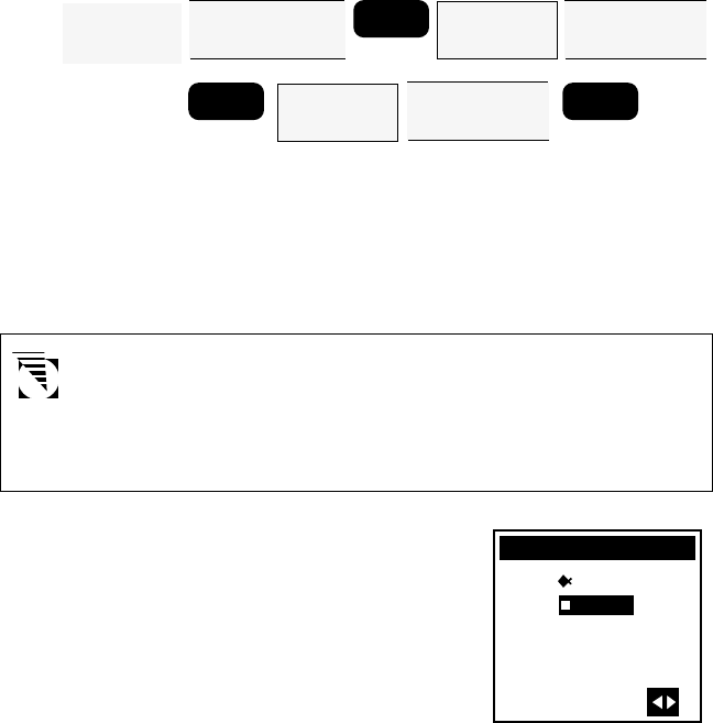
37
The receiver gives you one last chance to change your mind. Press
ENTER to confirm. The leg is removed from the route. Press any
function key to abort the process.
Adding a Leg
You can add a leg to the end of the route in much the same way as you
would insert a leg, only this time you add a waypoint to extend the end
of the route beyond the original destination.
Access the
ROUTE
MENU
Use ARROW KEYS
to highlight route to
be edited
ENTER
Highlight
EDIT
Press ENTER
Use UP/DOWN
ARROWs to select
the last route leg
ENTER
Highlight
ADD LEG
Press ENTER
ENTER
Use LEFT/RIGHT
ARROWs to select
"TO" waypoint
Access the ROUTE MENU and highlight the route to be edited. Press
ENTER to bring up the pop-up menu, highlight EDIT, and press ENTER.
Use the UP/DOWN ARROWs to view the last leg in the route. Press
ENTER to access the EDIT LEG menu, select ADD LEG, and press
ENTER.
If ADD LEG does not appear as an option of the Leg Edit menu,
you were not viewing the final leg of the route. To add a leg to
the end of a route, you must be viewing the final leg when you
access the Leg Edit menu. (To add a leg within a route, see
Inserting a Leg in a Route.)
The ADD LEG screen appears with the
destination waypoint of the route in the
FROM field. It is used as the starting
point of the final leg you wish to create.
A highlight bar appears for you to select
the new TO waypoint for this leg.
Use the LEFT/RIGHT ARROWs to scroll
through the waypoint list to the
waypoint you wish to use as the
destination for this new final leg and
press ENTER.
The new leg has now been added. The receiver displays the bearing
and distance for this new final leg.
ADD LEG 4
FROM FISH
TO
BRG
3.87
n
m
DST
287`
WPOO1
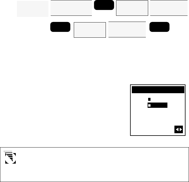
38
Replacing a Waypoint
This allows the destination (TO) waypoint of a leg to be changed to a
different waypoint.
Access the
ROUTE
MENU
Use ARROW KEYS
to highlight route to
be edited
ENTER
Highlight
EDIT
Press ENTER
Use UP/DOWN
ARROWs to select
the route leg
ENTER
Highlight
REPLACE
Press ENTER
ENTER
Use LEFT/RIGHT
ARROWs to select
"TO" waypoint
Access the ROUTE MENU and highlight the route to be edited. Press
ENTER to bring up the pop-up menu, highlight EDIT, and press ENTER.
Use the UP/DOWN ARROWs to view the leg to be modified. Press
ENTER to access the EDIT LEG menu, select REPLACE, and press EN-
TER.
A highlight bar appears for you to select
the new TO waypoint for this leg, replac-
ing the existing one.
Use the LEFT/RIGHT ARROWs to scroll
to the waypoint you wish to use as the
new destination for this leg of the route
and press ENTER.
The new TO waypoint must be different from the old (must have
a distance greater than 0.1 distance units from the "FROM"
waypoint)); the receiver will not replace a leg in this case but will
return to the leg screen you were viewing.
The destination has now been changed. The receiver has updated the
bearing and distance for this leg and displays it on the screen.
Press the DOWN ARROW. The following leg has also been changed.
The following leg now starts from the waypoint you designated as the
TO waypoint for the previous leg.
Navigating (Activating) a Leg
While navigating using a multileg route, one leg of the route is said to
be active. This is the leg that is currently being used to provide
navigational information. It is sometimes desirable to activate a different
leg, thereby changing the destination being navigated to.
REPLACE LEG 1
FROM JETTY
TO
BRG
1.58
n
m
DST
207`
WPOO3
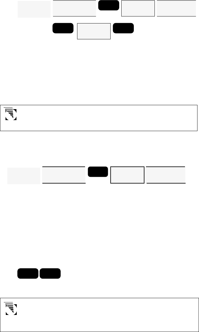
39
Access the ROUTE MENU and highlight the route to be edited. Press
ENTER to bring up the pop-up menu, highlight EDIT, and press ENTER.
Use the UP/DOWN ARROWs to view the leg to be activated. Press
ENTER to access the EDIT LEG menu, select NAVIGATE, and press
ENTER.
Press NAV or PLOT. The receiver begins navigating on the selected
leg.
If a route, GOTO, or MOB is already active, the leg you choose
to navigate automatically replaces it as the active leg.
Deleting a Route
This operation permanently removes a route from the Route Menu
returning the route to the "EMPTY" status.
Access the ROUTE MENU and highlight the route to be deleted. Press
ENTER to bring up the pop-up menu, highlight DELETE, and press
ENTER. Use the UP/DOWN ARROWs to confirm (YES) or abort
(NO) deleting the route. Press ENTER. The route has now been
deleted from memory.
Creating a MOB (Man OverBoard) Route
The MOB, or Man OverBoard function causes the receiver to save the
position that is current when the feature is accessed and to create a
one-leg route back to that position.
MOB ENTER
Press MOB. Highlight MOB and press ENTER.
If you have already saved an MOB position, the receiver gives
you the option of creating a new MOB position by displaying a
confirmation screen. To select a new MOB, press the DOWN
ARROW and ENTER.
Access the
ROUTE
MENU
Use ARROW KEYS
to highlight route to
be edited
ENTER
Highlight
EDIT
Press ENTER
Use UP/DOWN
ARROWs to select
the route leg
ENTER
Highlight
NAVIGATE
Press ENTER
ENTER
Access the
ROUTE
MENU
Use ARROW KEYS
to highlight route to
be cleared
ENTER Highlight
DELETE
Press ENTER
Highlight YES to
confirm and
press ENTER
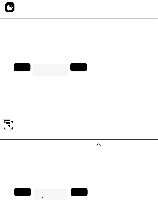
40
The MOB position and MOB route information will be lost when
the receiver is turned off.
Creating a Backtrack Route
This creates a route using fixes in the Last Fix Buffer (up to 16 of the
most recent last fixes) to create a route that “backtracks” the course
you last took. This way you could leave point A, travel for a couple of
hours, set a backtrack route, and the receiver would guide you back to
point A following the same course you just took.
Use ARROW KEYS
to highlight
BCKTRK
GOTO ENTER
Press GOTO, DOWN ARROW to highlight BCKTRK, and press ENTER.
A backtrack is created in the first available route.
The display returns to the last viewed NAV screen and shows navigation
information for the destination waypoint of the first leg of the
BACKTRACK route.
If all five routes are full a message screen appears indicating that
a route must be deleted in order to create a backtrack. (If this is
the case, see Deleting a Route.)
Backtrack waypoints use an up arrow ( ) icon to indicate that they
were created in backtrack. How many of these waypoints were created
(up to 16) is determined by the number of fixes in your last fix buffer.
Creating a COORD Route
The COORD option allows you to create a one-leg route to a position
not contained in the waypoint list, simply by providing its coordinates.
Use ARROW KEYS
to highlight
COORD
GOTO ENTER
Press GOTO, use the UP/DOWN ARROWs to highlight COORD and
press ENTER.
The COORD screen appears. The cursor is on the leftmost character
of the latitude field and the arrow icons indicate that the display is in
edit mode. The position shown is the last position fix taken.
Edit the coordinates using the UP/DOWN ARROWs to scroll through
and select numbers, and the LEFT/RIGHT ARROWs to move the
cursor. At the rightmost position, the UP/DOWN ARROWs toggle
between N/S and E/W if using LAT/LON coordinate system.
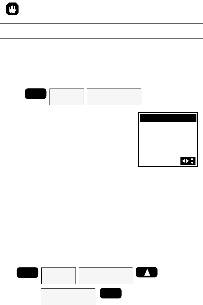
41
The receiver immediately begins navigating toward the selected
coordinates. The display returns to the last viewed NAV screen and the
words TO COORD appear in the title bar.
The COORD position and COORD route information will be lost
when the receiver is turned off.
Last Fix Buffer
While you are taking position fixes your receiver can automatically save
them. The receiver will store position fixes in the last fix buffer at a rate
you defined in SETUP under LAST FIX INTERVAL.
Viewing a LAST FIX
Press MENU and use the UP/DOWN
ARROWs to highlight LAST FIXES (on
the second page of the Function Menu)
and press ENTER. The LAST FIX screen
that appears exactly duplicates the
screen you have already seen when
viewing a waypoint.
MENU Highlight
LAST FIXES
Press ENTER
Use LEFT/RIGHT
ARROW keys to select
last fix
Notice that the receiver has assigned a name that begins with a plus (+)
and is followed by a two-digit number. This number will increase as the
Last Fixes are being taken with the higher the number, the older the fix.
The receiver will store a total of 16 Last Fixes.
Use the LEFT/RIGHT ARROWs to scroll through the other last fixes
in the buffer.
Viewing the LAST FIX Trip Summary Screen
This screen informs you that the summary you are about to view will
cover the trip you made from the time the selected last fix was recorded
to your present position (POS) or a different last fix.
ENTER
MENU
Highlight
LAST FIXES
Press ENTER
Use LEFT/RIGHT
ARROW keys to select
any last fix except +LFX01
Use LEFT/RIGHT
ARROW keys to select
"TO" last fix or POS
34`06.60N
117`49.57W
0 F T E L WGS84
10:06A24OCT96
LAST FIX
+LFX01
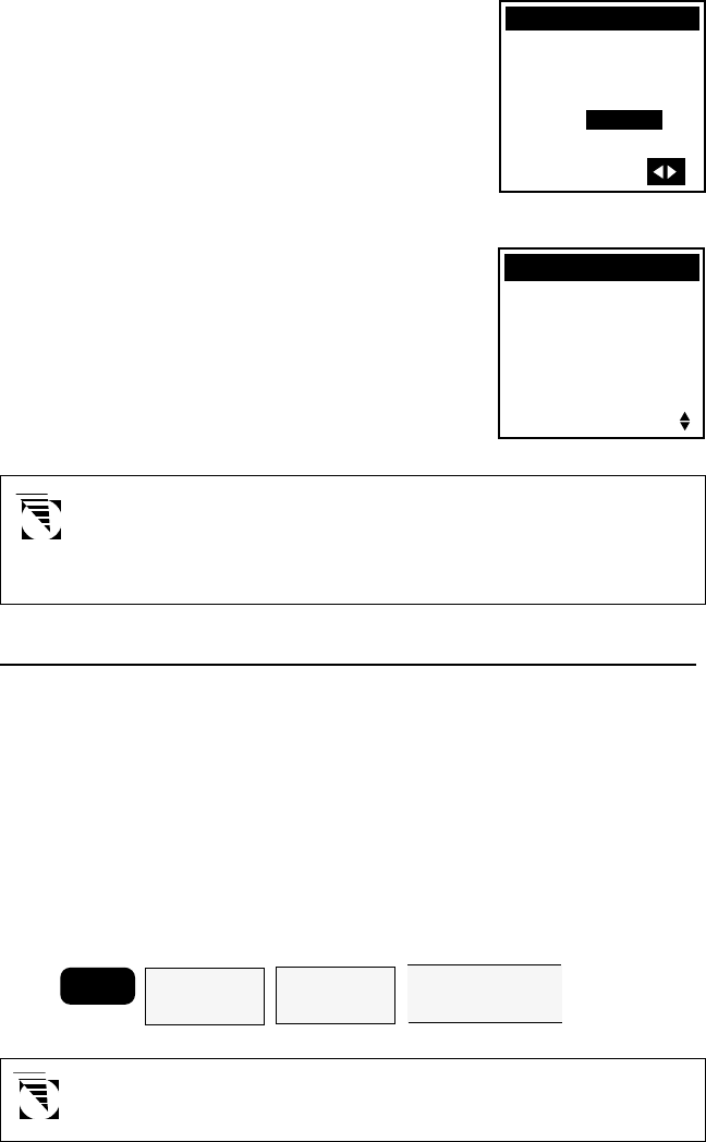
42
Press MENU and use the UP/DOWN
ARROWs to highlight LAST FIXES and
press ENTER. Use the LEFT/RIGHT
ARROWs to select any Last Fix except
+LFX01. Press the UP ARROW. Use
the LEFT/RIGHT ARROWs to select
any of the other fixes present in the last
fix buffer that were taken after the one
chosen as the “FROM” waypoint.
Press ENTER for the Trip Summary.
TRIP SUMMARY
+LFX16|POS
ODOM 0.91
TIME 2:28HR
MAX VEL 6.0KTS
MIN VEL 0.0KTS
AVG VEL 0.4KTS
n
m
If you select +LFX01 as the FROM waypoint you will not be
given the opportunity to change the “TO” waypoint since there
have been no other fixes saved since +LFX01 was recorded. A
message “SELECT OLDER STARTING FIX FOR TRIP” appears.
SETUP OPTIONS
Setup options allow you to customize your receiver to display information
in the format that best suits your needs.
Initializing the Receiver
This option was discussed in more detail earlier, but, in general,
INITIALIZE allows you to input the approximate coordinates, time, and
date for your present position if the receiver has computed a position
fix or if it has had its memory cleared. This function should also be
used any time the unit is moved more than 300 miles with the unit
turned off, to help the receiver acquire a fix faster.
MENU Highlight
SETUP
Press ENTER
Highlight
INITIALIZE
Press ENTER
Use ARROW KEYS
to enter coordinate
information
TRIP SUMMARY
FROM +LFX16
07:46A24OCT96
TO POS
10:14A24OCT96
For a more detailed description, refer to section on First Time
Use - Initializing the Receiver.
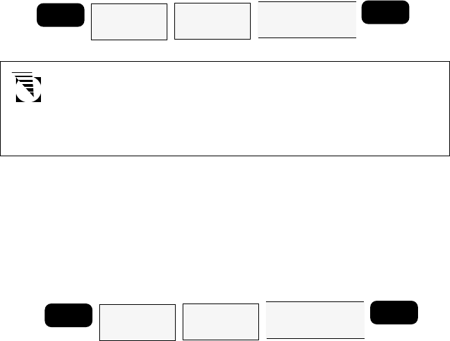
43
Setting the Coordinate System
The coordinate system you ultimately select will depend on the maps
or charts that you are using with your receiver. The default coordinate
system is LAT/LON, DEG/MIN.00.
If you select LAT/LON, you will be asked to select one of three
formats for displaying position coordinates: DEG/MIN.00, DEG/
MIN.000 or DEG/MIN/SEC. If you choose one of the first two
options, the display is in decimal format, while the third option is
based on 60 seconds in a minute.
Available Coordinate Systems:
LAT/LON OSGB SWEDISH GRID
UTM IRISH GRID FINNISH GRID
TD SWISS GRID
Setting the Elevation Mode
MENU Highlight
SETUP
Press ENTER
Highlight
COORD SYS
Press ENTER
Use UP/DOWN
ARROWS to select
coordinate system
ENTER
MENU Highlight
SETUP
Press ENTER
Highlight
ELEV MODE
Press ENTER
Use UP/DOWN
ARROWS to select
2D or 3D
ENTER
In addition to position, your receiver can compute your elevation when
it is receiving signals from at least four satellites. This is referred to as
“3D” Elevation Mode.
When there are only three satellites in view, the receiver cannot compute
elevation though it can still compute your position. In this case the
receiver will display the last computed elevation or the elevation that
you manually enter in INITIALIZE. This elevation mode is referred to as
“2D” (the default setting). You may select either elevation mode in this
SETUP feature.
If you select the 2D elevation mode you will be prompted to input the
elevation. If you are unsure of the elevation you can press ENTER to
accept the previously used elevation.
If you select the 3D elevation mode, the receiver will calculate elevation
whenever signals are being received from at least four satellites. When
fewer satellites are being tracked, the receiver will default to 2D and
display the 2D icon.
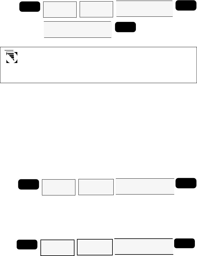
44
Selecting Time Display
Your Magellan receiver can display time in one of three formats: local
24-hour (military), local 12-hour (AM/PM), or UT (Universal Time or
Zulu). The default Time Display is LOCAL AM/PM.
MENU
Highlight
SETUP
Press ENTER
Highlight
TIME FORMAT
Press ENTER
Use UP/DOWN ARROWS
to select LOCAL AM/PM,
LOCAL 24HR, or UT
ENTER
If either local time format is
selected, use the ARROW KEYS
to modify the displayed time
ENTER
If the receiver does not have a computed position fix the receiver
displays a warning to alert you that an initial time has not been
set in INITIALIZE. After inputting an initial time you may change
the format that time is displayed in.
Setting Velocity Averaging
As you are travelling with your receiver on you may notice fluctuations
in the velocity displayed. Like elevation, velocity is very susceptible to
Selective Availability. Velocity Averaging will minimize this effect by
displaying an averaged speed measurement. You have three options to
choose from: OFF (no averaging) would be used where you require
rapid updates of velocity: 20 SECONDS would be selected where rapid
updates of velocity are not essential, generally at fairly low velocities; or
60 SECONDS where immediate velocity information is relatively
unimportant, such as a long journey at a constant speed. The default is
OFF.
MENU Highlight
SETUP
Press ENTER
Highlight
VELOCITY AVG
Press ENTER
Use UP/DOWN ARROWS to
select OFF, 20 SECONDS,
or 60 SECONDS
ENTER
Setting Speed Units
SPEED UNITS allows you to select the unit of measure for speed
measurements. You may choose from KNOTS, MILES/HR or KM/HR.
The default is KNOTS.
MENU Highlight
SETUP
Press ENTER
Highlight
SPEED UNITS
Press ENTER
Use UP/DOWN ARROWS
to select KNOTS, MILES/HR,
or KM/HR
ENTER
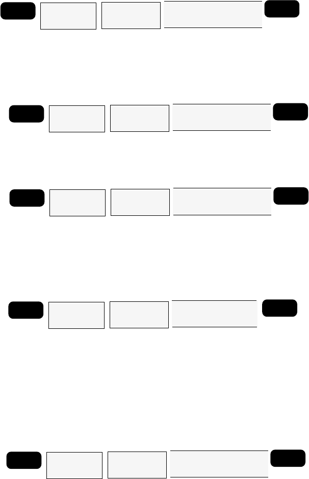
45
Setting Distance Units
DIST. UNITS (Distance Units) allows you to select the unit of measure
that distances will be displayed in. You may choose from NM (nautical
miles), ST.MILES (statute miles), or KM (kilometers). NM is the default
setting.
MENU Highlight
SETUP
Press ENTER
Highlight
DIST UNITS
Press ENTER
Use UP/DOWN ARROWS
to select NM, ST MILES,
or KM
ENTER
Setting Elevation Units
ELEV. UNITS (Elevation Units) is the same as DIST. UNIT but this time you
will select the unit of measure that will be used to display your elevation
in, METERS or FEET. The default setting is FEET.
MENU Highlight
SETUP
Press ENTER
Highlight
ELEV UNITS
Press ENTER
Use UP/DOWN ARROWS
to select FEET or
METERS
ENTER
Setting North Reference.
This sets the north reference of the displays to TRUE or MAGNETIC. The
default North reference is MAGNETIC.
MENU Highlight
SETUP
Press ENTER
Highlight
NORTH REF
Press ENTER
Use UP/DOWN ARROWS
to select MAGNETIC or
TRUE
ENTER
Selecting Map Datum
Depending upon which map or chart you are using you may need to
change the Map Datum that the receiver will use. The datum required
will be printed on the map or chart. The most common is WGS84,
which is also the default Map Datum.
MENU Highlight
SETUP
Press ENTER
Highlight
MAP DATUM
Press ENTER
Use UP/DOWN
ARROWS to select
Map Datum
ENTER
Setting NMEA
NMEA is the communication standard for electronic marine navigation
equipment. Your receiver outputs position and navigation information
in the NMEA 0183 format to support navigation aids such as autopilots.
To use NMEA your receiver must be connected to the NMEA device
with the Power/Data Cable and the device you’re using must accept
the proper 0183 format. Your GPS receiver must be on and computing
fixes before NMEA information will be output through the data port.
MENU Highlight
SETUP
Press ENTER
Highlight
NMEA
Press ENTER
Use UP/DOWN ARROWS
to select OFF, 0183A,
0183B, or 0183C
ENTER
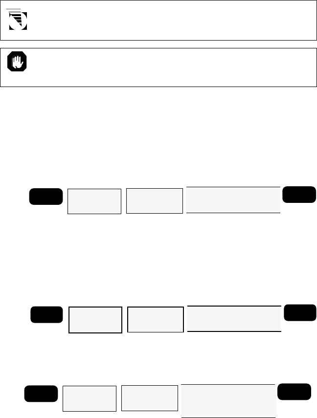
46
An optional Power/Data Cable is available for the Meridian XL
from your local dealer or directly from Magellan Systems.
Keep in mind that in order to support the NMEA device, your
receiver must be operating continuously. To prevent outages due
to low batteries, external power is recommended.
Selecting Baud Rate.
BAUD RATE allows you to select the appropriate baud rate for your
external equipment. (Check the documentation of your external
equipment.) You may choose from 1200, 4800, 9600 or 19200. The
default setting is 4800.
MENU Highlight
SETUP
Press ENTER
Highlight
BAUD RATE
Press ENTER
Use UP/DOWN ARROWS
to select 1200, 4800, 9600,
or 19200
ENTER
Selecting Waypoint Sort
WPT SORT allows you to classify the waypoints stored in the user
waypoint catalog in alphabetical order or according to their proximity
to the present position with the closest listed first. You may choose
from ALPHABETICAL, NEAREST or ICON. The default setting is
ALPHABETICAL.
Selecting the Last Fix Interval
This function allows you to set the rate that positions are automatically
saved to the last fix buffer. The default is 10 minutes.
MENU
Highlight
SETUP
Press ENTER
Highlight
LFIX INTERVAL
Press ENTER
Use UP/DOWN ARROWS to
select OFF, 10 MINUTES,
20 MINUTES, 30 MINUTES,
1 HOUR
ENTER
Plot Setup
PLOT SETUP allows you to adjust the track orientation and track history
on the PLOT screen.
For TRACK you may select OFF, 0.1, 0.5, 1.0, or 5.0. The default setting
is 1.0. For ORIENTATION, you may select HEADING UP or NORTH UP.
The default setting is HEADING UP.
MENU Highlight
SETUP
Press ENTER
Highlight
WPT SORT
Press ENTER
Use UP/DOWN ARROWS
to selectALPHABETICAL
NEAREST or ICON
ENTER
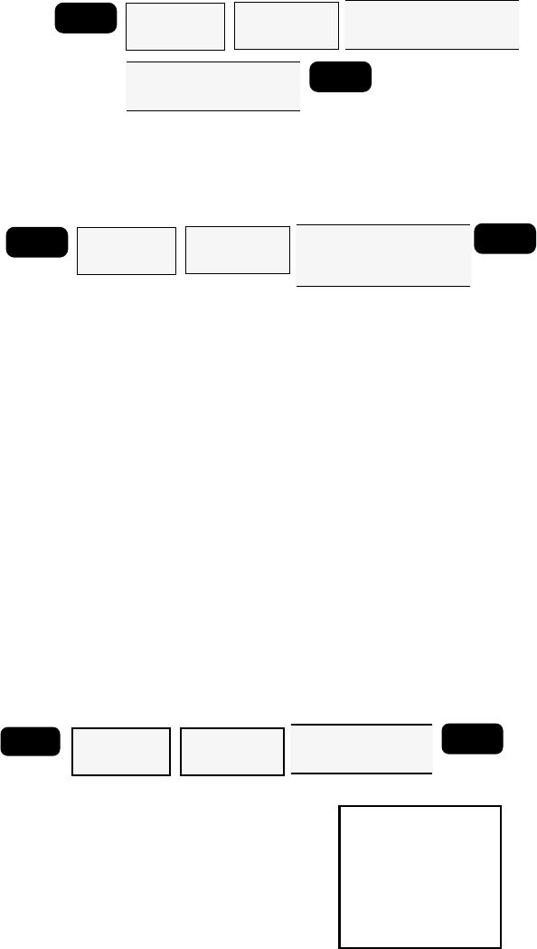
47
MENU
Highlight
SETUP
Press ENTER
Highlight
PLOT SETUP
Press ENTER
Use UP/DOWN ARROWS to
select ORIENTATION;
HEADING UP or NORTH UP
ENTER
Use LEFT/RIGHT ARROWS
to select TRACK; OFF, 0.1,
0.5, 1.0, or 5.0 NM
Sampling
Sampling causes the receiver to turn itself on every 10 minutes, 20
minutes, 30 minutes, or 1 hour, compute a position fix, store the fix in
the last fix buffer, and then turn itself off.
In order to use Sampling, the receiver’s antenna must remain in an
open area and fully visible to the sky. If the antenna is blocked so that
the receiver cannot acquire sufficient satellites the receiver will be unable
to compute a position fix and the receiver will remain on until the
obstruction is removed.
When Sampling is on, a warning message appears on the POWER DOWN
screen to remind you that you have Sampling on.
Sampling will continue until it is turned off or until the battery warning
is displayed.
When the unit is turned on again, a message will appear requiring you
to confirm whether you want SAMPLING on or off. Select ON or OFF
using the UP/DOWN ARROWs and press ENTER.
Power Lock
POWER LOCK allows you to safeguard the receiver's battery power in
case of unintentional power-on by requiring a specific key sequence to
confirm. This feature is useful, for example, when POWER key is pressed
accidentally as a result of being stored in a bag, etc.
When POWER LOCK is turned on,
the start-up screens include the
message screen shown at right.
When this key sequence is pressed,
the receiver continues to POSITION
screen or the initialization screens.
If any other key any is pressed, the
unit turns off instantly.
MENU
Highlight
SETUP
Press ENTER
Highlight
SAMPLING
Press ENTER
Use UP/DOWN ARROWS to
select OFF, 10 MINUTES,
20 MINUTES, 30 MINUTES,
1 HOUR
ENTER
MENU Highlight
SETUP
Press ENTER
Highlight
POWER LOCK
Press ENTER
Use UP/DOWN
ARROWS to select
OFF or ON
ENTER
PRESS
MENU THEN
RIGHT ARROW
THEN ENTER
TO CONTINUE
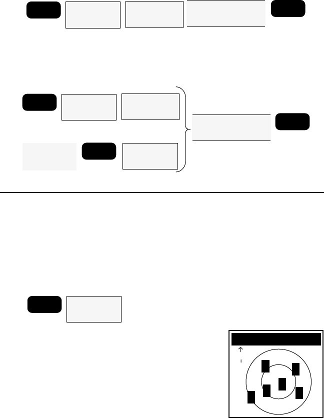
48
MENU
Highlight
SAT STATUS
Press ENTER
SAT STATUS
N
2
9
9
02
4
Note that the POWER LOCK feature remains active until it is
turned off under SETUP.
Light Intensity
LIGHT INTEN. allows you to select the brightness level (HIGH or LOW)
of the display. The light can be switched on and off by holding down
the “LIGHT” key.
Additional Features
Viewing the SAT STATUS Screen
This screen displays the satellites by their signal strength and their
position in the sky relative to your location. An asterisk (*) indicates
that the unit is not locked on to that particular satellite. When lock is
achieved the * will be replaced by the signal strength of the satellite.
Signal strength will range from 0 to 9, with 9 representing better signal
strength.
MENU Highlight
SETUP
Press ENTER
Highlight
CONTRAST
Press ENTER Use LEFT/RIGHT
ARROWS to adjust
contrast
OR
ENTER
From any
NAV or PLOT
Screen
Highlight
CONTRAST
Press ENTER
ENTER
MENU
Highlight
SETUP
Press ENTER
Highlight
LIGHT INTEN
Press ENTER
Use UP/DOWN
ARROWS to select
HIGH or LOW
ENTER
Contrast
CONTRAST allows you to adjust the contrast level of the display to
allow you to select the best contrast level for the particular environment
you are in.
Press MENU, highlight SAT STATUS and
press ENTER. The receiver displays the
SAT STATUS screen.
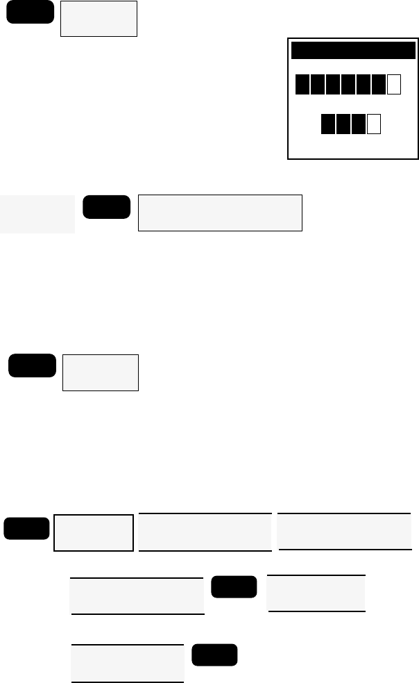
49
Viewing the Odometer
The Odometer feature displays the ODOMETER screen which keeps track
of total distance traveled as well as trip distance, similar to the odometer
in an automobile.
Press MENU, highlight ODOMETER on
the second page of the function menu
and press ENTER.
The ODOMETER screen appears, show-
ing the total distance traveled and the dis-
tance traveled on the current trip.
Resetting the Odometer and/or Trip Odometer
MENU Highlight
ODOMETER
Press ENTER
Highlight ESCAPE and press ENTER to return to the Odometer Screen.
Press any function key or the Menu key to exit the Odometer Screen.
Viewing the Clock
The Clock option will display the current date and time in the time
format selected during setup.
n
m
ODOMETER
000017
8
7
ODOMETER
TRIP ODOMETER
n
m
017
8
7
Press ENTER to return to the Function Menu.
Setting Alarms
Your Magellan receiver has the ability to sound an external alarm when
you arrive at your destination (ARRIVAL); have moved a predefined
distance from the place where you set your anchor (ANCHOR); and/or
if your cross track error is greater then the defined radius (XTE).
From the
Odometer
Screen
ENTER Highlight
RESET TRIP and/or RESET ODOM
and press ENTER
MENU Highlight
CLOCK
Press ENTER
MENU Highlight
ALARMS
Press ENTER
Use UP/DOWN ARROWS to
select ARRIVAL, ANCHOR,
or XTE
ENTER
To Set Alarm Radius:
Use ARROW
KEYS to enter
radius value
Use LEFT/RIGHT ARROWS
to turn alarm on or off
(check mark = ON)
Use UP/DOWN ARROWS to
select ARRIVAL, ANCHOR,
or XTE
To Exit Alarm Menu:
Use UP/DOWN
ARROWS to select
ESCAPE
ENTER
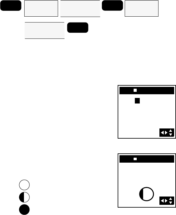
50
With the alarm menu displayed, you can turn an alarm on or off by
pressing the ENTER key.
If you turn on the ANCHOR, XTE or arrival alarms, you will have the
option of changing the radius of the selected alarm. The default is set
at 200 feet. If an alarm is turned on it will be preceded by a √ (check
mark). Use the LEFT/RIGHT ARROWs to turn alarms on and off.
Press ENTER, and use the UP/DOWN and LEFT/RIGHT ARROWs to
set radius of a selected alarm. To exit the ALARM MENU, highlight
ESCAPE and press ENTER.
Viewing the SUN/MOON Screen
This screen will display the time of sunrise and sunset for the chosen
waypoint. It also graphically displays the lunar cycle of the moon.
MENU Highlight
WAYPOINTS
Press ENTER
Use ARROW
KEYS to select
waypoint
ENTER Highlight
SUNRISE
Press ENTER
Use ARROW
KEYS to select
date to view
ENTER
Press MENU, use the UP/DOWN ARROWs to select WAYPOINTS
and press ENTER. Select the waypoint in the list for which you wish
to view sunrise information, then press ENTER to access the
WAYPOINT screen. Now press ENTER to access the function menu,
highlight SUNRISE and press ENTER.
The first step in viewing the solar and
lunar information is to enter the date
for which you want the information.
Use the UP/DOWN and LEFT/RIGHT
ARROWs to set the date and press
ENTER.
The receiver will compute the sunrise,
sunset, and lunar cycle for the waypoint
chosen on the date you entered.
Full moon
Half moon
New moon
JETTY
04OCT96
SUN ^ 06:47AM
SUN & 06:32PM
MOON
JETTY
06OCT96
SUN^
SUN&
MOON
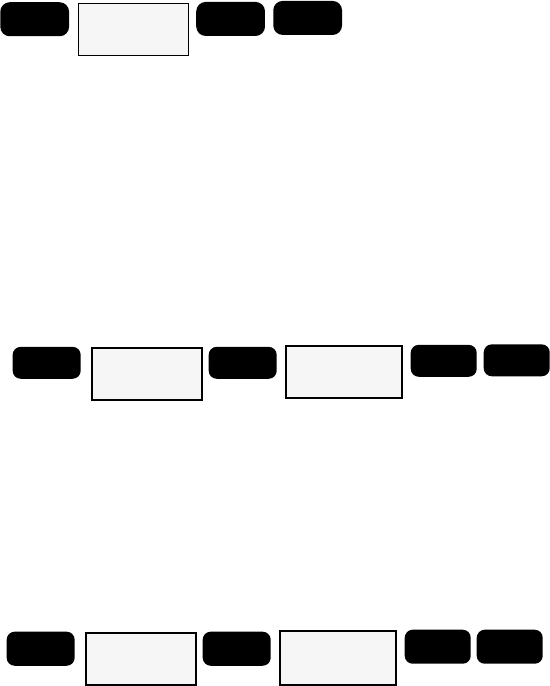
51
Simulator
The simulator mode causes the receiver to create a fictitious route from
your location to two newly created waypoints. You will find the Simulator
very handy when you want to review or practice using your receiver at
home. In the simulate mode you can watch the receiver simulate
movement and observe how the different navigational screens respond.
MENU
Highlight
SIMULATOR
Press ENTER
ENTER NAV
To activate, press MENU and use the UP/DOWN ARROWs to select
SIMULATOR, then press ENTER. You will then be prompted to press
NAV to return to the NAV Screen. After using the Simulator, be sure to
turn it off again by highlighting SIMULATOR function under the MENU
key and pressing ENTER. If you turn the receiver off before you turn
the simulator off, the waypoints and route it created will not be cleared.
Deleting Last Fixes
DELETE LFIX will erase all of the waypoints in your Last Fix Buffer.
Press MENU and highlight the CLEAR MENU. Press ENTER and use
the UP/DOWN ARROWs to highlight DELETE FIXES. You will be
instructed to press ENTER to delete the Last Fixes. If you change your
mind, press any other function key to leave the last fixes as they are.
Deleting Track from the Plotter Screen
As you use your receiver more you may soon notice the PLOT screen
becoming cluttered with the graphic display of your past movement
(track). You can delete the track display with the DELETE TRACK option.
Use the UP/DOWN ARROWs to highlight DELETE TRACK and press
ENTER. You will be asked to press ENTER to confirm that you want
to delete the track history. If you change your mind, press any other
function key to leave the track as it is.
MENU Highlight
CLEAR MENU
Press ENTER
ENTER Highlight
DELETE LFIXES
Press ENTER
ENTER ENTER
MENU Highlight
CLEAR MENU
Press ENTER
ENTER Highlight
DELETE TRACK
Press ENTER
ENTER ENTER
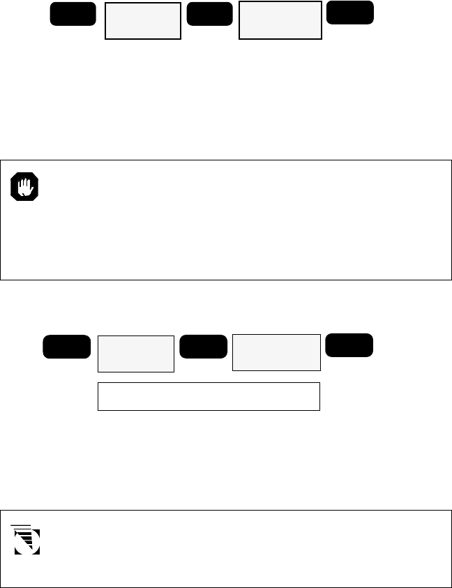
52
Delete All Waypoints from Waypoint List
DELETE WPTS will delete all of the waypoints in your waypoint list. If
routes currently exist, deleting waypoints requires that all routes be
deleted and a message will be displayed. See Deleting Routes.
Highlight DELETE WPTS using the UP/DOWN ARROWs and press
ENTER. You will be instructed to press ENTER to erase the waypoints.
If you change your mind, press any other function key to leave the
waypoints intact.
Clearing Receiver Memory
This reset will erase all of the waypoints in your receiver’s
memory. Before selecting Clear Menu we recommend that you
review the waypoints in your waypoint library, recording on
paper the coordinates for any waypoint that you want to use in
the future. After turning the receiver back on, you can enter
those waypoints again.
Clear Memory will erase all of your receiver’s memory including resetting
all of the Setup features to their default values.
MENU Highlight
CLEAR MENU
Press ENTER
ENTER Highlight
CLEAR MEMORY
Press ENTER
ENTER
Press keys as instructed by receiver
To access Clear Memory, use the UP/DOWN ARROWs to highlight
CLEAR MEMORY and press ENTER. You will then be given instructions
as to which keys to simultaneously hold down to reset your receiver.
If you change your mind, simply press any function key to escape.
Note that it is not required that you go to the SETUP menu to do
a reset; holding down the proper keys at any time will reset your
receiver.
The keys to press simultaneously are NAV, GOTO, LIGHT, and MENU.
If you do not wish to delete anything from the receier's memory, select
ESCAPE to exit the Clear Menu.
MENU Highlight
CLEAR MENU
Press ENTER
ENTER Highlight
DELETE WPTS
Press ENTER
ENTER ENTER
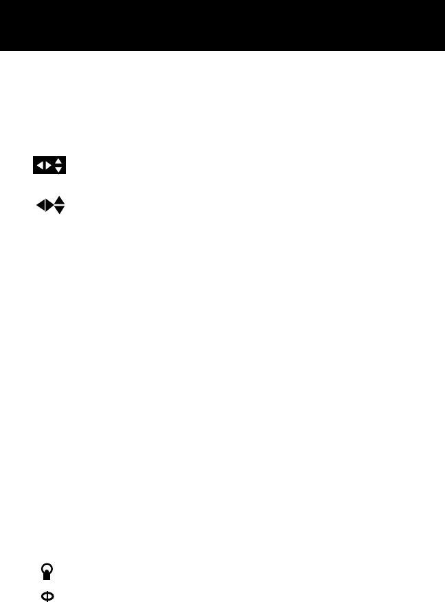
53
Status Line Icons
Status appear on most screens and provide you with some valuable
information as to the status of the position fixes that are being computed.
Most information on this line will be represented by icons which appear
before the arrows on the right side of the status line. These arrows have
two functions, depending on how they are displayed.
Inverted arrow icons in the lower right corner indicate that the
ARROW keys are used to enter or edit information.
Non-inverted arrow icons indicate that there are other screens
accessible from this screen using the ARROW keys.
ÜPoor Geometric Quality. Appears when the Geometric Quality
(GQ) of a position fix is below a set value and the accuracy of the
position fix is questionable. Position information displayed may
not be accurate enough to be used for navigation.
ÄOld Data. The Old Data icon (“hourglass”) appears when the
receiver has been unable to update the position fix. The position
information displayed is that of the last position fix computed.
Position and navigation information displayed while the Poor
Geometric Quality and Old Data icons are being displayed may
be inaccurate and should not be used for navigation.
ÑLow Signal Quality. Is displayed if the Signal Quality (SQ) of one
or more satellites used to compute a position fix drops below a
minimum level. This has a minimal effect on accuracy, and is
intended only to alert you that a signal may soon be lost.
ÇTwo Dimensional. The 2D icon indicates that the receiver is not
receiving signals from at least four satellites to compute elevation
information. The 2D icon is also displayed when you have selected
2D in the ELEV. MODE portion of Setup.
Light On. Indicates that the display light is on.
Simulator . Indicates that the simulator function is activated.
DDifferential. Indicates that the unit is receiving differential
information.
LOW BAT Battery Warning. This is warning you that you need to
replace the batteries very soon or risk losing stored data.
54
Troubleshooting
frozen display, Remove power and wait for the receiver to turn
keypad does not off. Remove and reinsert batteries. Turn power back
on and press ENTER.
OR
Use the four-finger reset NAV, GOTO, LIGHT and
MENU pressed together.
The reset will clear the receiver’s memory.
no power Check how the batteries were inserted into the tray;
are they oriented correctly? The batteries may also
have run down completely.
If operating from external power, the receiver may
not have been hooked up correctly, or the external
power source is not operating. Check the connec-
tions, and be sure the external power source is
operating correctly.
Use only the Magellan Power/Data Cable to connect the receiver
to external power.
position fix If the old data icon (Ä) is displayed, the signal from
doesn’t change one or more satellites has been lost, and the receiver
has been unable to reacquire or replace it. The
displayed fix is at least 10 seconds old, and should
not be used for navigation.
If there is no old data icon, the display may be
frozen. Press any key to change the display. If the
display does not changed, refer to “frozen display.”
position fix Small changes in the position coordinates and
fluctuates elevation are normal. They are caused by several
variables, including the geometric quality of the fix
and the effects of SA. Geometric quality is a mea-
surement of the probable accuracy of a fix based on
the position of the satellites being used in relation to
each other.
NMEA device is The receiver may be outputting an NMEA data
not responding message that is not compatible with the NMEA
respond
55
device; check the message format selected with
SETUP. Also check the connection between the
receiver and the device, and be sure the device is on.
If supporting an autopilot, be sure that a route has
been set and activated.
How to Contact Customer Service
The list above should allow you to solve most of the operating problems
you are likely to encounter. Simply disconnecting the unit from power for
a moment may solve your problem. If this does not help, try clearing the
receiver's memory in the Setup Menu and reinitializing your receiver.
If you are unable to solve your operation problems, please call Magellan's
Customer Service at 909-394-5000. Representatives are available Monday
through Friday, from 8 A.M. to 5 P.M., Pacific Standard Time. Faxes can
be sent to Customer Service at 909-394-7050.
If necessary, you can also return your unit to Magellan for repair. (Please
call for assistance first.) If possible, please notify us before shipping the
unit by Parcel Post or UPS, and include with the unit a description of the
problem and your name and address. If your return shipping address is
different, please include it.
With all correspondence, please be sure to state the model of the receiver
you have and if calling, please be sure to have your unit with you.
Packages should be sent to:
Magellan Systems Corporation
960 Overland Court
San Dimas, CA 91773
Attn.: Warranty/Repair
Appendix

56
In addition to the items provided with the receiver, optional accessories
are also available.
Mounting Kit Includes a mountable bracket for hands-free operation, a
9–16 VDC Power/Data Cable, the Antenna Extension Cable, and the
Antenna Suction Cup Mount. The Extension Cable and Suction Cup Mount
are required to operate with the quadrifilar antenna detached. Do not
alter the length of the antenna extension cable or use a non-Magellan
cable, as this may adversely affect receiver sensitivity.
External Antenna An external antenna that is mounted to a range pole
or vehicle roof in order to provide satellite signals to the receiver when
being operated in a sheltered location. Does not require a separate power
source. Comes with 30 feet of connecting cabling and mounting hardware.
Magnetic Mount for External Antenna A magnetic mounting device
used to temporarily mount the external antenna to a flat metal surface.
Ordering Instructions (Mail, FAX, or Phone)
By Mail: Complete the order form provided with this manual, adding
shipping and handling changes, and sales tax where applicable. Include
a check, money order or credit card information and send it to:
Magellan Systems Corporation
Attention Order Department
960 Overland Court
San Dimas, CA 91773-1742 USA
By FAX: Complete the order form, adding shipping and handling
charges, and sales tax where applicable. Include your credit card
information and FAX the form to (909) 394-7050.
By Phone: Complete the order form provided with this manual,
adding shipping and handling changes, and sales tax where applicable.
Have the order form and your credit card information ready and phone
the Magellan Order Hotline at (909) 394-6067. You can then place
your order via voice mail. Please leave your phone number should we
need to contact you concerning your order.
Optional Accessories

57
List of Available Datumss
INDIA Indian (India, Nepal)
IRAN Iran
IRELA Ireland 1965
KAUAI Kauai
KERTA Kertau 1948
KKJ KKJ (Finland)
LIBER Liberia 1964
LUZON Luzon
MASSA Massawa
MAUI Maui
MERCH Merchich
MINNA Minna
MONTJ
NAHRW Nahrwan, Saudi Arabia
OAHU Oahu
OEGYP Old Egyptian
OHAWA Old Hawaiian
OMAN Oman
PITCA Pitcairn Astro 1967
QATAR Qatar National
QORNO Qornoq
RT90 Rt90 (Sweden)
SAM56 Provisional So. Am. 1956
SAM69 South American 1969
SCHWA Schwarzeck
SICIL Sicily
SIERR
SWISS
TANAN Tananarive Observatory 1925
THAI Indian (Thailand, Vietnam)
TIMBA Timbalai
TOKYO Tokyo
VOIRO
WGS72 World Geodetic System 1972
YACAR Yacare
ZANDE Zanderij
WGS84 World Geodetic System
NAD27 North American 1927
NAD83 North American 1983
ADIND Adinda
ALASK Alaska
ARC50 Arc 1950
ARC60 Arc 1960
ASTRO Camp Area Astro
AUS66 Australian Geodetic 1966
AUS84 Australian Geodetic 1984
BOGOT Bogota Observatory
BUKIT Bukit Rimpah
CAMPO Campo Inchauspe
CANAD Canada
CAPE Cape
CARTH Carthage
CENAM Central America
CHATH Chatham 1971
CHUAA Chau Astro
CORRE Corrego Alegre
CYPRU Cyprus
DJAKA Djakarta (Batavia)
EGYPT Egypt
EUROP European 1950 (All of Europe)
EUR50 European 1950 (W. Europe)
EUR79 European 1979
GANDA Gandajika Base
GEO49 Geodetic Datum 1949
GHANA
GRB36 Ordnance Survey of GB, 1936
GUAM Guam
GUNSG G. Segara
GUNSR
HAWAI Hawaii
HERAT Herat North
HJORS Hjorsey 1955
HUTZU Hu-tzu-shan

58
NMEA Message Sets
Data Transfer
Your GPS receiver can be set to output GPS data in the NMEA 0183
format to interface with other marine devices.
The dataport must be turned on and the output message format
selected in SETUP.
NMEA DATA MESSAGES. NMEA data is output at the baud rate selected
in Setup, 8, N, 1, checksum off. These settings are acceptable to most
equipment and software applications.
There are several NMEA output message sets, each with a slightly different
application. Check the documentation for your external equipment to
select the appropriate message set.
SET OUTPUT/USAGE
0183A BWC, APA, GLL, VTG
Remote displays, version 1.x marine autopilots
0183B RMC, RMB
NMEA-recommended navigation data for remote map, etc.
0183C APB, GGA, BWC, GLL, VTG
Version 2.0 marine autopilot data and satellite data
NMEA Message Definitions
APA Autopilot cross track error, direction to steer, status of GPS, route
status, destination waypoint name, and bearing from origin to
destination (old format).
APB Revised autopilot message contains all of the above plus: heading
to steer toward destination, bearing from the present position
to the destination (magnetic or true).
BWC Range and bearing to a waypoint
GGA GPS position, time, fix quality, number of satellites used, HDOP
(Horizontal Dilution of Precision), differential reference
information, and age.
GLL GPS-derived latitude, longitude, and time of fix.
RMB Data status, cross track error, direction to steer, origin, destination
waypoint, waypoint location, bearing to destination, and velocity
toward the destination.
59
RMC Time, latitude, longitude, speed over ground, course over
ground, and date.
VTG Track (magnetic and true) and groundspeed (knots and KPH).
OUTPUT DATA FORMAT
APA Autopilot Format A
1 2 3 4 5 6 7 8 9 10
APA,A,A,X.XX,L,N,A,A,XXX.,M,CCC
1 OR’ed Blink and SNR (A = valid, V = invalid)
2 Cycle Lock (A = valid, V = invalid)
3-5 Cross Track, Sense (L = steer left, R = steer
Right), N.Mi. Units
6-7 Arrival Circle, Arrival Perpendicular (crossing
of the line which is perpendicular to the course
line and which passes through the destination
waypoint.
8-9 Bearing dest. wpt. from origin wpt., Magnetic
10 Dest wpt. identifier
APB Autopilot Sentence “B”
1 2 3 4 5 6 7 8 9 10 11 12 13 14
APB,A,A,x.x,a,N,A,A,x.x,a,c—c,x.x,a,x.x,a*hh
1 Status: V = Loran-C Blink or SNR warning
A = general warning flag for other
navigation systems when a
reliable fix is not available.
2 Status: V = Loran-C cycle lock warning flag
A = OK or not used
3 Magnitude of XTE
4 Direction to steer (L, R)
5 XTE units, nautical miles
6 Status: A = arrival circle entered
7 Status: A = perpendicular passed at waypoint
8-9 Bearing origin to destination, M/T
10 Destination waypoint ID
11-12 Bearing, present position to destination,
Magnetic or True
13-14 Heading to steer to destination waypoint,
Magnetic or True
60
BWC To Selected Waypoint, Great Circle
1 2 3 4 5 6 7 8 9 10 11 12
BWC,XXXXXX,XXXX.XX,N,XXXXX.XX,W,XXX.,T,XXX.,M,XXX.X,N,CCCC
1 UTC of Bearing
2-3 Lat, N or S of waypoint
4-5 Long, E or W of waypoint
6-7 Bearing, True
8-9 Bearing, Magnetic
10-11 Distance, naut. miles
12 Waypoint identifier
GGA Global Positioning System Fix Data
1 2 3 4 5 6 7 8 9 1011
GGA, hhmmss.ss,111.11,a,yyyyy.yy,a,x,xx,x.x,x.x,M,x.x,
1213 14
M,x.x,xxxx*hh
1 UTC of Position
2-3 Latitude – N/S
4-5 Longitude - E/W
6 GPS Quality Indicator
0 = fix not available or invalid
1 = GPS Fix
2 = Differential GPS Fix
7 Number of satellites in use
8 Horizontal dilution of precision
9 Antenna altitude above/below mean sea level
10 Units of antenna altitude
11 Geoidal separation – difference between the
WGS-84 earth ellipsoid and mean sea level
(geoid), “-” = mean sea level below ellipsoid
12 Units of geoidal separation, meters.
13 Age of Differntial GPS data – Time in seconds
since last SC104 Type 1 or 9 update, null
field when DGPS is not used
14 Differential reference station ID, 0000-1023
61
GLL Geographic Position — Latitude/Longitude
1 2 3 4 5 6
GLL,1111.11,a,yyyyy.yy,a,hhmmss.ss,A*hh
1-2 Latitude, N/S
2-3 Longitude, E/W
4 UTC of position
6 Status A = Data valid
RMB Generic Navigation Information (immediately follows RMC)
1 2 3 4 5 6 7 8 9 10 11 12
RMB,A,X.XX,L,CCCC,CCCC,SSS.SS,N,XXXXX.XX,W,XXX.X,XXX.,XX.X,
13 14
A *XX
1 Status (A = valid, V = invalid)
2-3 XTE, naut. miles and direction to steer (L or
R) [If XTE exceeds 9.99 NM, display 9.99 in
field 2.]
4 Origin waypoint ID
5 Destination waypoint ID
6-7 Destination Waypoint Latitude (N or S)
8-9 Destination Waypoint Longitude (E or W)
10 Range naut. miles, present fix to destination
waypoint Great Circle. [If range exceeds
999.9 nm, display 999.9.]
11 Bearing, True, Great Circle, Present fix to
dest. waypoint
12 Closing velocity to destination, knots
13 Arrival (OR’ed arrival circle and crossing of
line which is perpendicular to the course line
and which passes through the destination
waypoint.)
14 CHECKSUM (Mandatory in this sentence.)
62
RMC Transit Specific (to be followed by RMB)
1 2 3 4 5 6 7 8 9 10 12
RMC,XXXXXX,A,XXXX.XX,N,XXXXX.XX,W,XX.X,XXX.,XXXXXX,XX.,E *XX
1 Time, UTC
2 Status (A = valid, V = invalid)
3-4 Latitude at UTC time, N or S
5-6 Longitude at UTC time, E or W
7 Speed over ground, knots
8 COG (track), degrees
9 Date (DDMMYY)
10 Variation, degrees
11 Variation, sense (E or W)
12 CHECKSUM (Mandatory in this sentence)
VTG Actual Track and Ground Speed (SOG)
1 2 3 4 5 6 7 8
VTG,XXX.,T,XXX.,M,XX.X,N,XX.X,K
1-2 Track degrees, True
3-4 Track degrees, Magnetic
5-6 Speed, knots
7-8 Speed, kilometers/hour
The formats listed are NMEA formats and Magellan receivers may not
output all of the information listed for a particular format.

63
City Reference Chart
Australia & SW Pacific
Adelaide 34°55.00 S 138°35.00 E
Alice Springs 23°42.00 S 133°53.00 E
Apia 13°48.00 S 171°45.00 W
Auckland 36°55.00 S 174°47.00 E
Bourail 21°34.00 S 165°29.00 E
Brisbane 27°28.00 S 153°02.00 E
Canberra 35°17.00 S 149°08.00 E
Coober Pedy 28°56.00 S 134°45.00 E
Dampier 20°45.00 S 116°48.00 E
Darwin 12°28.00 S 130°50.00 E
Derby, WA 17°19.00 S 123°38.00 E
Honiara 9°28.00 S 159°57.00 E
Iron Range 12°39.00 S 143°13.00 E
Mount Isa 20°50.00 S 139°29.00 E
Nadi 17°47.00 S 177°29.00 E
Newman, Mt. 23°20.00 S 119°34.00 E
Ooldea 30°30.00 S 131°45.00 E
Perth 31°56.00 S 115°50.00 E
Port Moresby 9°30.00 S 147°07.00 E
Rawlinna 31°00.00 S 125°21.00 E
Timaru 44°23.00 S 171°14.00 E
Townsville 19°13.00 S 146°48.00 E
Asia
Bangalore 12°58.00 N 77°35.00 E
Bangkok 13°44.00 N 100°30.00 E
Beijing 39°55.00 N 116°26.00 E
Bombay 18°56.00 N 74°35.00 W
Calcutta 22°30.00 N 88°20.00 E
Colombo 6°55.00 N 79°52.00 E
Delhi 28°40.00 N 77°14.00 E
Hanoi 21°01.00 N 105°52.00 E
Harbin 45°45.00 N 126°41.00 E
Ho Chi Minh City 10°46.00 N 106°43.00 E
Hong Kong 22°15.00 N 114°10.00 E
Islambad 33°40.00 N 73°08.00 E
Jakarta 6°08.00 S 106°45.00 E
Kagoshima 31°37.00 N 130°32.00 E
Kandla 23°03.00 N 70°11.00 E
Karachi 24°51.00 N 67°02.00 E
Kathmandu 27°42.00 N 85°19.00 E
Kinabalu, Gunung 6°03.00 S 116°32.00 E
Kota, Malaysia 2°33.00 N 102°10.00 E
Kuala Lumpur 3°08.00 N 101°42.00 E
Kunming 25°04.00 N 102°41.00 E
Malang 7°59.00 S 112°45.00 E
Mandalay 21°57.00 N 96°04.00 E
Nagpur 21°10.00 N 79°12.00 E
Padang 6°12.00 S 120°27.00 E
Palu 8°19.00 S 121°44.00 E
Pinang 5°30.00 N 100°28.00 E
Pontianak 0°05.00 S 109°16.00 E
Rangoon 16°47.00 N 96°10.00 E
Sapporo 43°05.00 N 141°21.00 E
Seoul 37°30.00 N 127°00.00 E
Shanghai 31°06.00 N 121°22.00 E
Sorong 0°50.00 S 131°17.00 E
Surakarta 7°32.00 S 110°50.00 E
Tanahmerah 6°08.00 S 140°18.00 E
Tapei 25°05.00 N 121°32.00 E
Thimphu 27°32.00 N 89°43.00 E
Tokyo 35°40.00 N 139°45.00 E
Tonhil 46°19.00 N 93°54.00 E
Ulaanbaatar 47°54.00 N 106°52.00 E
Ürümqi 43°43.00 N 87°38.00 E
Wuhan 30°35.00 N 117°55.00 E
Xi’an 34°16.00 N 108°54.00 E
Yumen 39°54.00 N 97°43.00 E
CIS
Anadyr 64°50.00 N 177°50.00 E
Arkhangel’sk 64°32.00 N 40°40.00 E
Ashkhabad 37°58.00 N 58°24.00 E
Baku 40°22.00 N 49°53.00 E
Balkhash 46°50.00 N 74°57.00 E
Barnaul 53°21.00 N 83°45.00 E
Chita 52°03.00 N 113°35.00 E
Gizhiga 62°00.00 N 160°34.00 E
Igarka 67°31.00 N 86°33.00 E
Inarigda 63°15.00 N 107°40.00 E
Kargasok 59°07.00 N 80°58.00 E
Khatanga 71°59.00 N 102°31.00 E
Kiyev 50°25.00 N 133°43.00 E
Krasnodar 45°02.00 N 39°00.00 E
Magdagachi 53°27.00 N 125°44.00 E
Moscow 55°45.00 N 37°42.00 E
Okhotsk 59°20.00 N 143°15.00 E
Perm 58°01.00 N 56°10.00 E
Petropavlovsk 54°53.00 N 69°13.00 E
Riga 56°40.00 N 106°10.00 E
Saratov 51°30.00 N 45°55.00 E
Tashkent 41°16.00 N 69°13.00 E
Tulun 54°32.00 N 100°35.00 E
Vanino 49°05.00 N 140°14.00 E
Vladivostok 43°09.00 N 131°53.00 E
Vorkuta 67°27.00 N 64°00.00 E
Yakutsk 62°10.00 N 129°50.00 E
Middle East
Al Kuwayt 29°20.00 N 48°00.00 E
Ar Riyad 24°39.00 N 46°46.00 E
Baghdad 33°20.00 N 44°26.00 E
Bam 36°57.00 N 57°56.00 E
Halab 36°14.00 N 37°10.00 E
Herat 34°20.00 N 62°12.00 E
Jerusalem 31°47.00 N 35°13.00 E
Kabul, Afghanistan 34°31.00 N 69°12.00 E
Mashhad, Iran 36°16.00 N 59°34.00 E
Nazwá22°56.00 N 57°33.00 E
Salalah 17°00.00 N 54°04.00 E
San’ a15°24.00 N 44°14.00 E
Shiraz 29°38.00 N 52°34.00 E
Tabriz 38°05.00 N 46°18.00 E
Tarim 16°08.00 N 48°58.00 E
Tehran 35°40.00 N 51°26.00 E
Africa
Abidjan 5°19.00 N 0°05.00 W
Ad Dakhla 23°43.00 N 15°57.00 W
Adis Abeba 9°03.00 N 38°42.00 E
Alger 36°50.00 N 3°00.00 E
Antananarivo 18°52.00 S 47°30.00 E
Asmera 15°20.00 N 38°58.00 E
Aswân24°05.00 N 32°56.00 E
Bamako 12°39.00 N 8°00.00 W
64
Oslo 59°55.00 N 10°45.00 E
Paris 48°52.00 N 2°20.00 E
Reykjavik 64°09.00 N 21°51.00 W
Scoresbysund 70°30.00 N 22°00.00 W
Stensele 65°05.00 N 17°10.00 E
Stockholm 59°20.00 N 18°03.00 E
Thule 76°35.00 N 68°30.00 W
Torshavn 62°02.00 N 6°47.00 W
Trabzon 41°00.00 N 39°43.00 E
Vardo 60°16.00 N 20°20.00 E
The Americas
Albany, NY 42°39.00 N 73°45.00 W
Alburquerque 35°05.00 N 106°39.00 W
Amarillo 35°14.00 N 101°50.00 W
Antofagasta 23°40.00 S 70°23.00 W
Arequipa 16°25.00 S 71°32.00 W
Atlanta 33°44.00 N 84°23.00 W
Baton Rouge 30°27.00 N 91°09.00 W
Belem 1°27.00 S 48°29.00 W
Billings, MT 45°47.00 N 108°30.00 W
Birmingham 33°31.00 N 86°48.00 W
Bismarck 46°48.00 N 100°47.00 W
Bogotá4°36.00 N 74°05.00 W
Boise 43°36.00 N 116°12.00 W
Boston 42°21.00 N 71°03.00 W
Brasilia 15°47.00 S 47°55.00 W
Buffalo, NY 42°52.00 N 78°55.00 W
Caracas 10°30.00 N 66°56.00 W
Casper 42°50.00 N 106°20.00 W
Cayenne 4°56.00 N 52°20.00 W
Chicago 41°51.00 N 87°39.00 W
Chihuahua 28°40.00 N 106°06.00 W
Churchill, CAN 58°45.00 N 94°00.00 W
Cleveland 41°29.00 N 81°41.00 W
Comodoro R 45°50.00 S 67°30.00 W
Coppermine 67°49.00 N 115°21.00 W
Córdoba, Veracruz 18°55.00 N 96°55.00 W
Cuiabá7°15.00 S 58°25.00 W
Dallas 32°46.00 N 96°47.00 W
Denver 39°44.00 N 104°59.00 W
Des Moines 41°36.00 N 93°36.00 W
Detroit 42°20.00 N 83°03.00 W
Duluth 46°45.00 N 92°10.00 W
Fort McPherson 67°29.00 N 134°50.00 W
Fort Providence 61°03.00 N 117°40.00 W
Georgetown, Guy. 6°48.00 N 58°10.00 W
Grand Rapids, MI 42°57.00 N 86°40.00 W
Guadalajara 20°40.00 N 103°20.00 W
Guantánamo 20°09.00 N 75°14.00 W
Guatemala 14°38.00 N 90°31.00 W
Guayaquil 2°10.00 S 79°50.00 W
Hazelton, BC 55°15.00 N 127°38.00 W
Houston 29°45.00 N 95°21.00 W
Ilhéus 14°50.00 S 39°06.00 W
Indianapolis 39°46.00 N 86°09.00 W
Iquitos 3°51.00 S 73°13.00 W
Kansas City, MO 39°02.00 N 94°33.00 W
La Habana 23°08.00 N 82°22.00 W
Labrador City 52°56.00 N 66°52.00 W
Las Vegas 36°10.00 N 115°08.00 W
Lima 12°03.00 S 77°03.00 W
Little Rock 34°44.00 N 92°17.00 W
Los Angeles 34°03.00 N 118°14.00 W
Louisville 38°15.00 N 85°45.00 W
Managua 12°06.00 N 86°18.00 W
Manaus 3°06.00 S 60°00.00 W
Merida, Venezuela 8°24.00 N 71°08.00 W
Banghazi 32°07.00 N 20°04.00 E
Bangui 4°22.00 N 18°35.00 E
Beira 19°49.00 S 34°52.00 E
Cairo 30°03.00 N 31°15.00 E
Capetown 33°55.00 S 18°22.00 E
Dakar 14°40.00 N 17°26.00 W
Fés34°05.00 N 5°00.00 W
Freetown 8°30.00 N 13°15.00 W
Harare 17°50.00 S 31°03.00 E
Kabwe 14°29.00 S 28°25.00 E
Kampala 0°19.00 N 32°25.00 E
Kano 12°00.00 N 8°31.00 E
Khartoum 15°36.00 N 32°32.00 E
Kinshasa 4°18.00 S 15°18.00 E
Kisangani 0°33.00 N 25°14.00 E
Lagos 6°27.00 N 3°24.00 E
Las Palmas de GC 28°08.00 N 15°27.00 W
Lindi 10°00.00 S 39°41.00 E
Lobito 12°20.00 S 13°34.00 E
Lomé6°08.00 N 1°13.00 E
Lubumbashi 11°41.00 S 27°29.00 E
Lüderitz 26°38.00 S 15°10.00 E
Lusambo 4°59.00 S 23°26.00 E
Maputo 25°58.00 S 32°35.00 E
Maseru 29°19.00 S 27°29.00 E
Mbale 1°04.00 N 34°12.00 E
Mogadishu 2°02.00 N 45°21.00 E
Monrovia 6°18.00 N 10°47.00 W
Mwanza, Zaire 7°51.00 S 26°43.00 E
N’ Djamena 12°10.00 N 14°59.00 E
Nairobi 1°17.00 S 36°49.00 E
Namibe 15°10.00 S 12°09.00 E
Nouakchott 18°09.00 N 15°58.00 W
Ouagadougou 12°22.00 N 1°31.00 W
Pointe Noire 4°46.00 S 11°53.00 E
Port Elizabeth 33°58.00 S 25°36.00 E
Sabha, Libya 27°02.00 N 14°26.00 E
Serowe 22°25.00 S 26°44.00 E
Sidi Ifni 29°24.00 N 10°12.00 W
Toliara 23°20.00 S 43°41.00 E
Tombouctou 16°49.00 N 2°59.00 W
Tripoli 32°54.00 N 13°11.00 E
Tsumeb 19°13.00 S 17°42.00 E
Tunis 36°48.00 N 10°11.00 E
Winhoek 22°34.00 S 17°06.00 E
Yaounde 3°52.00 N 11°31.00 E
Zanzibar 6°10.00 S 39°20.00 E
Europe
Athens 37°58.00 N 23°43.00 E
Barcelona 41°23.00 N 2°11.00 E
Bern 46°57.00 N 7°26.00 E
Bordeaux 44°50.00 N 0°34.00 W
Brno 49°13.00 N 16°40.00 E
Bucuresti 44°26.00 N 26°06.00 E
Budapest 47°30.00 N 19°05.00 E
Cork 51°54.00 N 8°28.00 W
Gdansk 54°23.00 N 18°40.00 E
Glasgow 55°53.00 N 4°15.00 W
Godthåb64°11.00 N 51°44.00 W
Hamburg 53°33.00 N 9°59.00 E
Istanbul 41°01.00 N 28°58.00 E
London 51°30.00 N 0°10.00 W
Longyearbyen 78°12.00 N 15°40.00 E
Madrid 40°24.00 N 3°41.00 W
Napoli 40°51.00 N 14°17.00 E
Nice 43°42.00 N 7°15.00 E
Nuugaatsiaq 71°30.00 N 53°00.00 W
65
Miami 25°46.00 N 80°11.00 W
Milwaukee 43°02.00 N 87°54.00 W
Minneapolis 44°58.00 N 93°15.00 W
Montevideo, Uru. 34°53.00 S 56°11.00 W
Nakina 59°12.00 N 132°48.00 W
Nashville, TN 36°09.00 N 86°47.00 W
New York 40°43.00 N 74°01.00 W
Norfolk, VA 36°50.00 N 76°17.00 W
Oklahoma City 35°28.00 N 97°30.00 W
Omaha 41°15.00 N 95°56.00 W
Panama City 8°58.00 N 79°32.00 W
Peace River 56°15.00 N 117°18.00 W
Peoria, IL 40°43.00 N 89°38.00 W
Phoenix 33°26.00 N 112°04.00 W
Pittsburgh 40°26.00 N 79°59.00 W
Port-au-Prince 18°32.00 N 72°20.00 W
Portland, OR 45°31.00 N 122°40.00 W
Porto Velho 8°45.00 S 63°54.00 W
Québec 46°50.00 N 71°15.00 W
Rapid City, SD 44°06.00 N 103°14.00 W
Recife 8°06.00 S 34°53.00 W
Reno 39°32.00 N 119°49.00 W
Rio de Janeiro 22°54.00 S 43°14.00 W
Salt Lake City 40°45.00 N 111°53.00 W
San Antonio 29°25.00 N 98°29.00 W
San Francisco 37°46.00 N 122°25.00 W
San Juan 18°28.00 N 66°07.00 W
Santarém2°26.00 S 54°41.00 W
São Paulo 23°32.00 S 46°37.00 W
Saskatoon 52°10.00 N 101°32.00 W
Seattle 47°36.00 N 122°19.00 W
Shreveport 32°30.00 N 93°46.00 W
Sioux Falls 43°34.00 N 96°42.00 W
Spokane 47°40.00 N 117°25.00 W
St Louis 38°37.00 N 90°11.00 W
Tampa, FL 27°58.00 N 82°38.00 W
Tijuana 32°32.00 N 117°01.00 W
Toronto 43°39.00 N 79°23.00 W
Valparaiso, Brazil 21°16.00 S 50°54.00 W
Vancouver 49°16.00 N 123°07.00 W
Veracruz 19°12.00 N 96°08.00 W
Washington 38°53.00 N 77°02.00 W
Whitehorse 60°43.00 N 135°03.00 W
Wichita 37°43.00 N 97°20.00 W
Winnipeg 49°53.00 N 97°09.00 W
Pacific Ocean
American Samoa 14°20.00 S 170°00.00 W
Baker I. 0°12.00 N 176°28.00 W
Easter I. 27°05.00 S 109°20.00 W
Gambier I. 23°10.00 S 135°00.00 W
Honolulu 21°18.00 N 157°51.00 W
Howland I. 0°48.00 N 176°38.00 W
Jarvis I. 0°02.00 S 160°02.00 W
Kanton I. 2°50.00 S 171°40.00 W
Lihue 21°59.00 N 159°23.00 W
Palmyra I. 5°52.00 N 162°05.00 W
Pitcairn I. 25°04.00 S 130°06.00 W
Swains I. 59°30.00 S 100°00 W
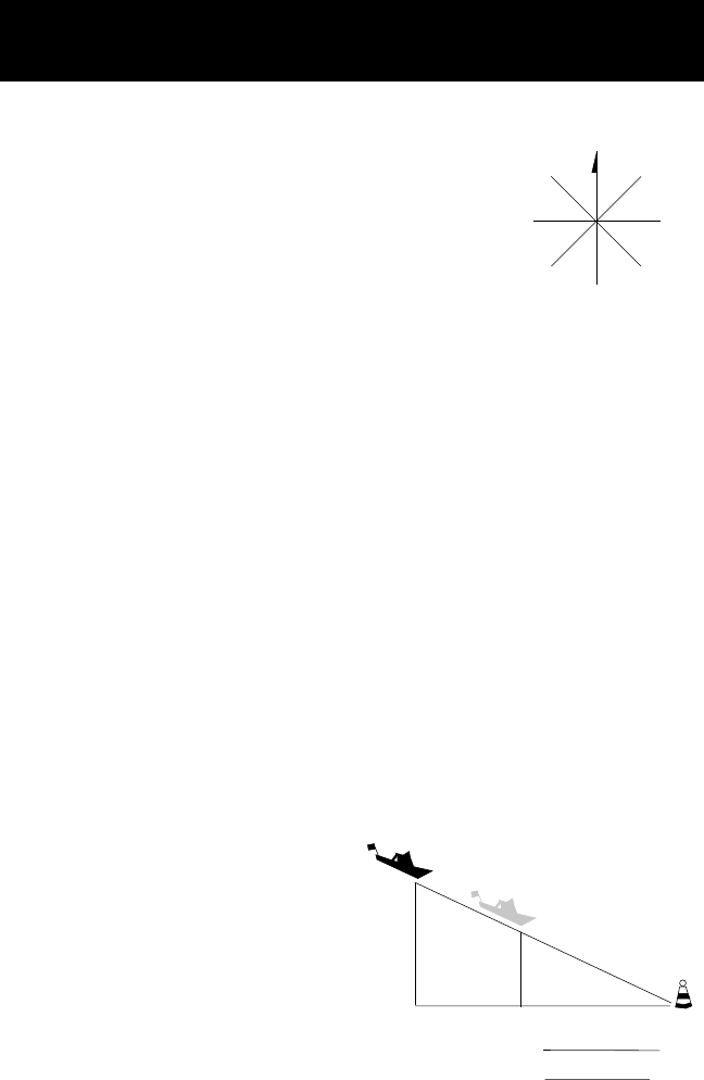
66
A
A1
B
B1
A1
AB
B1
Abbreviations and Data Terms
EXPLANATION OF DATA TERMS
BRG. Bearing is the direction, as measured in de-
grees from north in a clockwise direction. The re-
ceiver uses either true north or magnetic north, as
selected in the Setup Menu. The illustration shows
a simple compass rose with the eight cardinal direc-
tions noted with their bearing.
COG. Course over ground is the direction of movement expressed as bearing.
If a boat is pointing exactly north (0°) and there are no other factors affecting
its travel, the COG would be 0° but that is rarely the case. Water currents and
wind can affect the course the boat is taking.
If there is a current passing from left to right across the boat (90°) the COG
would change even though the bow of the boat is still pointing north. COG is
measured in degrees with North being 0°.
CTS. The optimum direction the vessel should be steered in order to effi-
ciently make headway back to the courseline while also proceeding toward
the destination waypoint. It is a "compromise" course bearng that projects
from your current position to a point on the courseline mid-way between a
point perpendicular to your position and the current leg destination waypoint.
DST. Distance to go to an active waypoint, or the distance between two
waypoints in a route leg.
ETA. Estimated time to arrival.
SOA. Understanding speed of advance is a little tricky but once you do it
becomes fairly simple. For this example we will use an exaggerated sample so
as to clearly describe SOA.
The boat is heading towards the buoy
and is currently at point A. If the boat
had followed its original course (A1 –
buoy), it would be somewhere on the
line A1 — B1. (The XTE for this sample
is the distance between points A and
A1.) In 1 hour he is at point B and
has travelled 34 NM (equivalent to a
speed of 34 knots).
Now if you project downwards to the course he should be on, you arrive at
point B1.
N
0°
E
90°
W
270°
S
180°
NW
315°NE
45°
SW
225°SE
135°
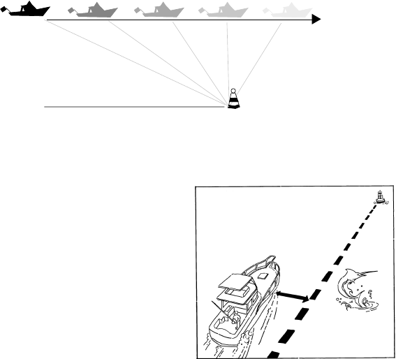
67
Comparing the lines from points A and B and from points A1 and B1 you see
that while the boat travelled 34 NM it only moved 30 NM along the courseline.
If he moves 30 NM on the courseline in 1 hour, his SOA is 30 knots, whereas
SOG would be 34 knots.
SOG. Speed over ground is the speed at which the vehicle/vessel is moving in
respect to the earth. SOG is sometimes referred to as ground speed and is
measured in knots, miles per hour, and kilometers per hour. (This is not the
same as speed through water.)
STR. The difference between COG and BRG. If BRG is180° and COG is 183°,
then STR is 3° Left.
TTG. Time to go to the active waypoint.
VMG. Velocity made good is the portion of the velocity that is in the direction
of the destination. In the above example, the boat is travelling directly to-
wards the buoy even though not on the courseline originally set. In this case,
all of this velocity is being applied towards arriving at the destination, (i.e.,
VMG = SOG). Should the boat veer away from this course and travel in a line
parallel to the original courseline (A1;B1) he would be travelling on a course
that would not intercept the buoy waypoint. As the boat moved along, less
and less of his velocity would be applied toward arriving at the buoy. By the
time point D is reached, none of the velocity is applied to getting closer to the
buoy and the VMG would be 0. As he moves to point E, he is moving away
from the buoy and his VMG is a negative value.
A
Courseline
BCDE
XTE. XTE (cross track error) is the distance to the left or right of the courseline
that you are travelling. As you will see in the discussion of other data items,
XTE is important in computing them accurately.
Keeping XTE at a minimum will help
maintain the most direct route to your
destination. This illustration shows a
boat and the courseline. The arrows
between the boat and the courseline
is the distance of XTE that this boat is
to the left of the courseline. This boater
would need to steer right to close the
XTE.

68
Specifications
Specifications
Size 6.125” x 3.5” x 1.25”, not including antenna
(15.6 cm x 8.9 cm x 3.2 cm)
Weight 14 ounces (0.397 kg), with batteries installed
Temperature:
Operating 14˚F to 140˚F (-10˚C to 60˚C)
Storage -40˚F to 167˚F (-40˚C to 75˚C)
Case waterproof (non-submersible)
Antenna detachable quadrifilar
Operating Characteristics
Accuracy:
Position 12 meters RMS in 3D operation without SA
Velocity 0.5 meters/second RMS
Speed limit up to 951 MPH (1,530 kilometers per hour)
Elevation limit upper limit 57,414 feet (17,500 meters)
lower limit -328 feet (-100 meters)
Time to First Fix:
Cold start* 3 minutes or less
Warm start* 1 minute
After memory loss 15 minutes or more
* Warm start: the receiver has obtained a position fix within the last
2 hours. Cold start: the receiver has been idle for 2 hours or longer.
Storage capacity up to 200 waypoints, up to five 15-leg routes
Update rate every second
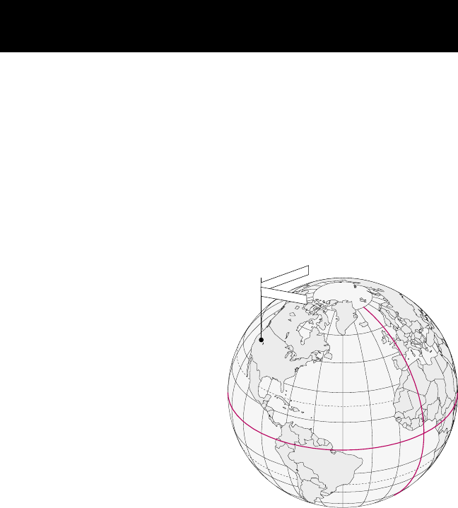
69
Coordinate Systems
Positions are locations that are described in a unique way so that one
locations cannot be confused with another. This is done by using a
coordinate system to describe locations. Your Magellan receiver has the
ability to use any one of four different coordinates systems; LAT/LON
(latitude and longitude), TD (Time Difference of Arrival), UTM (Universal
Transverse Mercator), and OSGB. The one you select (in SETUP) will be
determined by the maps and charts you use; you would generally want
the receiver to display position coordinates in the same system that is
used by your maps.
LAT/LON Coordinate System. LAT/LON is the most commonly used
coordinate system today. It projects lines of latitude (parallels) and lines of
longitude (meridians) onto the
earth’s surface. Lines of latitude
are the equator and the
horizontal lines that are parallel
to it. Lines of longitude are the
vertical lines that are
perpendicular to the equator
and pass through the poles. A
position is described as being
the intersection of a line of
latitude and a line of longitude.
Specifically, a position is so many
degrees north or south of the
equator (up to the poles, which
are 90˚N and 90˚S; the equator
is 0˚ latitude), and so many degrees east or west of the Prime Meridian,
which is 0˚ longitude. (The Prime Meridian passes through Greenwich,
England.) Parts of a degree are minutes; there are 60 minutes (written as
60') to a degree. Minutes can also be divided into smaller units. Fractions
of a minute can be expressed as decimals or as seconds. (There are 60
seconds to one minute, written as 60"). So a Lat/Lon position coordinate
can be expressed in two ways, which your Magellan GPS receiver displays
as 25°47.50 or 25°47’30.
UTM Coordinate System. Another commonly used coordinate system
is UTM (Universal Transverse Mercator), which is generally found on land-
based maps and quad sheets that are produced by government map
providers. On land, you may find that UTM coordinates are easier to use
than Lat/Lon.
E
Q
U
A
T
OR
0
°
P
R
I
M
E
M
E
R
ID
I
A
N
0
°
L
a
t
i
t
u
de
Lo
n
gi
tud
e
115°00.00W
42°30.00N
70
UTM coordinates are easy to use, but since the model it is based on is
somewhat abstract, this section is a very simplified introduction to UTM.
Instead of projecting an imaginary grid of intersecting lines onto the globe,
UTM projects sections of the globe onto a flat surface. Each of these
sections is called a “zone.” There are 60 zones to cover the entire earth
between 84˚N and 80˚S (polar areas are not described by UTM). Each
zone is 6˚ wide as projected from the earth’s center.
A UTM position is described by three elements; the zone it is in, the easting,
and the northing. Eastings and northings measure how far into a zone a
position is in meters. Eastings are an east/west measurement, and
correspond roughly to longitude. Northings are a north/south
measurement, and correspond to latitude.
This chart shows the position of Magellan Systems described in both Lat/
Lon and UTM coordinates.
LAT/LON UTM
DEG/MIN DEG/MIN/SEC
34˚06.58N 34˚06’35"N 11 4 23 818 E
117˚49.56W 117˚49’34"W 37 74 624 N
1511 12 13 14
3000 Km
3000 Mi.
Scale at the Equator.
12345
180°150°
10
120°90°
20
60°
25
30°
30
0°
35
30°
40
60°
45
90°
50
120°
55
150°
60
180°
0°
NOTE: The area described by the UTM coordinate system extends to 84°N and to 80°S.
6789 16171819 21222324 26272829 31323334 36373839 41424344 46474849 51525354 56575859

71
TD Coordinate System. TDs are indicated on many nautical charts in
addition to the LAT/LON marks. They are established lines of position
(LOPs) that are determined by the difference in the length of time required
to receive Loran-C signals. Many coastal navigators use TDs because Loran
is a familiar radio aid navigation and TDs are clearly marked on their charts.
The Meridian XL can display position coordinates in TDs by converting
from position fixes calculated in Lat/Lon. (No measurements are made
using the Loran signals.)
To use TDs, the Loran receiver is set to a specific chain of stations; each
Loran chain consists of one master station (designated as M) and two or
more secondary stations (W, X, Y, and Z). Next, the navigator determines
which two secondary stations will provide the most accurate position fix
based on the angle of intersection of the LOPs. The TD measurement is
the difference between the time it takes a signal to arrive from the master
station and the time it takes to arrive from a secondary station to your
location. This is referred to as a TD. Two TDs are required for a position
fix.
The Meridian XL displays position coordinates in TDs by converting the
LAT/LON coordinates to TDs, mathematically, using the GRI (chain number)
and secondary beacons you entered when selecting the TD coordinate
system.
When TD is selected in Setup under COORD SYS you will be asked to
select the following
1) The GRI (also called the chain) that you will be navigating in.
2) The two secondary stations that will provide you with the best
angle of LOP intersections. If you have used Loran in the past, you
should simply enter the values that you have used before.
Other Coordinate Systems. OSGB coordinates are similar to UTMs, but
they describe only Great Britain. They must be used with the GBR36 datum,
which also describes Great Britain. This coordinate system cannot be used
in any other part of the world. The Meridian XL automatically selects the
GBR36 datum when the OSGB coordinate system is selected in Setup.
(While OSGB coordinates must be used with the GBR36 datum, the GBR36
datum can be used with LAT/LON coordinates; just be sure the map you
are using uses both LAT/LON and GBR36.)
If you select OSGB in the COORD. SYS. portion of the Setup
Menu be sure to change the map datum back to the one you
will be using (WGS84 is the default) when changing to another
coordinate system.
Irish Grid uses the Ireland datum, Swedish Grid uses the RT90 datum,
Swiss Grid uses the Swiss datum and Finnish Grid uses KKJ datum.
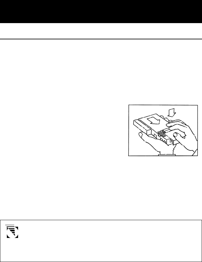
72
General Maintenance
Meridian XL
The Meridian XL is powered by three AA batteries. It can also be powered
from an external DC power source by using the optional Power/Data Cable.
Batteries
We suggest using AA alkaline batteries to power the receiver. (Magellan
Systems recommends Eveready Energizer™ batteries.) Alkaline batteries
will power the receiver for 6 hours or more of continuous operation.
To install the batteries, hold the receiver as
shown in the illustration at the right. At
the same time, press down slightly on the
battery compartment cover and pull the
cover toward you. Insert batteries as
indicated in the compartment and replace
the cover.
When the battery power level drops, a warning message will appear on
all displays (LOW BATT). The receiver should still have sufficient power to
operate for up to 30 minutes if alkaline batteries are being used.
When the batteries no longer hold enough power to operate the receiver,
the receiver turns itself off. The batteries will still be able to maintain the
memory for a time, but the receiver can be operated only if external
power is supplied or if fresh batteries are installed.
Batteries are not recharged in the receiver. The low battery
warning appears approximately 10 minutes before the receiver
automatically powers down to preserve memory. When batteries
are changed, you have 15 to 20 minutes to install fresh batteries
without losing memory.
It is possible to use rechargeable batteries, but there are a couple of things
you should be aware of when using them. Commercially available NiCad
batteries typically have poor power performance after repeated use, and
rechargeable alkaline batteries maintain only 50% of the useful life of
standard alkaline batteries. Rechargeables also have a very sudden power
drop at the end of their charge. The drop may be so sudden that the
battery warning is not displayed, although memory can be maintained
for a while.

73
External Power
The Meridian XL can also be operated from an external DC power source.
This requires the Power/Data Cable that is included with the optional
mounting kit. (Even when operating from external power, the receiver
must have batteries; the batteries will be used to maintain memory when
the receiver is off.)
The cable converts DC power to a level usable by the receiver. It also can
be used to output positioning data to electronic navigation equipment
that conforms to NMEA standards, and to import broadcast differential
corrections from a differential beacon receiver.
The use of a non-Magellan cable or an altered Magellan cable
may damage the receiver and will void the warranty.
Antenna
The receiver has an attached quadrifilar antenna, which rotates 360˚. Using
the extension cable and suction cup provided with the optional Mounting
Kit, the antenna can also be detached from the receiver and temporarily
mounted to any convenient surface. (The antenna is detached by rotating
it until its base is parallel with the display, then pulling it away from the
receiver.) Since it can be used detached from the receiver, the antenna
can be placed wherever it has the clearest view of the sky.
In order to provide the best signal reception possible, the antenna must
be vertical. If attached to the receiver, rotate the antenna from its storage
position to the upright position. If detached from the receiver, the antenna
should be mounted as vertically as possible with the connecting cable at
the bottom.
GPS signals will pass through glass and canvas (such as bimini tops)
however, you may experience some signal loss in areas of heavy foliage.
(Do not stand under a tree in full leaf when attempting to take a fix.)
Signals will not go through metal, and you are unlikely to obtain signals
in a permanent structure.
Signals can be temporarily blocked by trees, masts, and people. If you are
unable to obtain satellite signals when out of doors, try moving slightly to
get a better view of the sky. If the receiver is being operated in a covered
location (such as a navigation station), you may want to use the optional
External Antenna Kit. (Use only a Magellan antenna; the use of a non-
Magellan antenna may greatly degrade the performance of the receiver.)
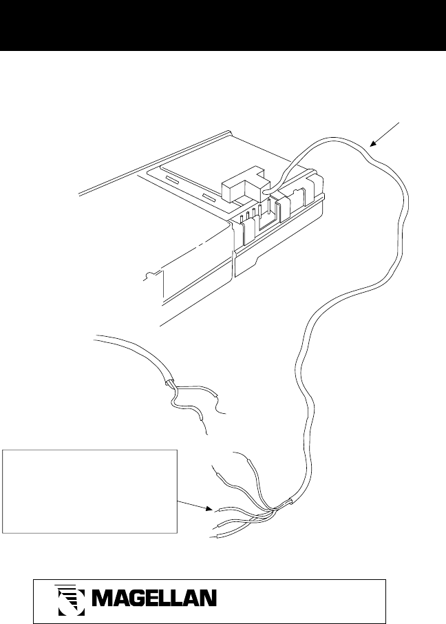
74
Power/Data Cable Instruction Sheet
22-60067-001
(–)
(–) (+)
(+)
DC POWER SOURCE
(10 – 35 VDC)
or
Magellan Cigarette
Lighter Adapter connected to
10 – 35 VDC power source
[Black with white strip wire is
positive]
Black
Red
Red
Black
Orange
Yellow
White
Power (+)
Power (–) NMEA (-)/DBR (-)
NMEA (+)
DBR + (Optional)
External Alarm, (optional on
some models)
Power/Data
Cable
SYSTEMS CORPORATION
960 Overland Court
San Dimas, California 91773
(909) 394-5000
Warning - Attach the power/data cable to the port of the black Trailblazer XL, Part
No.00-62006-003 and the Black Meridian XL, Part No. 00-12004-000 ONLY.
Power/Data Cable Instruction Sheet

75
The Global Positioning System
What Is GPS?
GPS is a constellation of navigation satellites that orbit the earth. The precise time
and position information transmitted by these satellites is used by a GPS receiver
to triangulate a position fix.
The system is now officially declared “initial operational,” and provides continuous,
24-hour 3D (position plus elevation) coverage anywhere on the earth.
GPS was developed by the United States Department of Defense to provide
consistent, reliable navigation information that is unaffected by rough terrain and
bad weather, and is highly resistant to multipath errors and interference. The DoD
continues to administer and control the Global Positioning System.
Although GPS was developed as a military navigation system, its civilian and
commercial uses were recognized. The satellites therefore transmit two codes, a
military-only encrypted code (PPS) and a civilian-access, Standard Positioning Service
(SPS) code. All commercial and consumer GPS receivers are SPS receivers.
How Does GPS Work?
Each GPS satellite transmits its precise location (position and elevation) and the
start time of the transmission. A GPS receiver acquires the signal, then measures
the interval between transmission and receipt of the signal to determine the
distance between the receiver and the satellite: this is ranging. Once the receiver
has computed range for at least three satellites, its location on the surface of the
earth can be determined.
Each satellite transmits two types of data,
almanac and ephemeris. Almanac data is
general information on the location and
health of each satellite in the constellation.
Since it contains general information, an
almanac can be collected from any satellite.
A receiver with a current almanac in its
memory knows where in the sky to look for
satellites, given its last known position and
the time of day. Ephemeris data is the precise
satellite positioning information that is used
for ranging. Each satellite transmits its own
ephemeris data.
Both almanac and ephemeris data are required for a GPS receiver to locate and
acquire satellites quickly and compute a position fix.
E
Q
U
A
T
OR
0
°
P
R
I
M
E
M
E
R
I
D
I
A
N
0
°
L
a
t
i
t
u
d
e
L
o
n
gitud
e
115°00.00W
42°30.00N

76
Accuracy
GPS positioning with an SPS receiver that is intended for general use will produce
accuracies of 25 meters or better.
In fact, SPS receivers have proven to be far more accurate than anyone anticipated.
DoD has decided that 25-meter accuracy is a potential risk, and has introduced
Selective Availability (SA) to maintain a military advantage. SA is a random error
that is introduced to the SPS code ephemeris data and reduces the accuracy of
any SPS receiver. The size of the error changes, but rarely exceeds 100 meters.
The DoD civil GPS user policy is that GPS accuracy as affected by SA is sufficient
for general navigation. In an open environment, it usually is. Even with SA, a GPS
receiver will bring you within visual range of a destination or target, and GPS
remains the best available source of accurate, repeatable navigation and positioning
information.
If you feel that you really need 25-meter accuracy, the effects of SA can be overcome
with a technique called broadcast differential to produce highly accurate position
fixes.
DGPS
Differential GPS (DGPS) computes the size of the error and applies it to positioning
information. There are several ways to perform DGPS, one of which is broadcast
differential. Broadcast differential uses GPS receivers at control sites to measure
the range errors for all visible satellites and determines a correction for each satellite.
These corrections are broadcast in the RTCM SC-104 format by a radio beacon at
the control site to any differential beacon receiver that is within range of the
signal.
The differential beacon receiver receives and demodulates the signal, then relays
it to the user’s differential-ready GPS receiver. The user’s GPS receiver applies the
corrections to the positioning information it collects to compute differentially
corrected position and navigation data.
This technique requires that your GPS receiver be connected to a compatible
differential beacon receiver (such as the Magellan DBR™, which is compatible
will all differential-ready Magellan receivers). You must also be within range of a
differential radio beacon.

77
More Information on GPS
There are many sources for more information on GPS and navigation.
The sources listed here are just a few of the books, magazines, and Internet
addresses that deal with GPS. Your local library is a good source for
technical books on GPS and navigation.
GPS Information Center
The GPS Information Center provides general information on the Global
Positioning System and satellite status. This center is operated by U.S.
Coast Guard for the Department of Transportation, and was established
to provide information and to serve as a point of contact for civilian
GPS users.
•Voice telephone recording for constellation status: (703) 313-5907
•Computer bulletin board: (703) 313-5910 (up to 14,400 bps)
(8 data bits, 1 stop bit, no parity)
•24 hour operator: (703) 313-5900; fax: (703) 313-5920
A Comprehensive Guide to Land Navigation with GPS
An excellent book written by Noel J. Hotchkiss and published by Alexis
Publishing. ISBN No: 0-9641273-2-6. This book uses the Magellan
Trailblazer to discuss and describe land navigation with a GPS receiver.
The book is very easy to read and gets into detail the art of navigating
with GPS. (Available from Navtech Seminars.)
Newsgroups (Internet)
Several USENET newsgroups have occasional postings related to GPS.
Some of the more popular newgroups for GPS are:
• sci.geo.satellite-nav
• rec.aviation.products
• rec.boats
• sci.space
• sci.space.news
78
GPS World Magazine
Monthly magazine covering a wide variety of uses for GPS receivers.
Advanstar Communications
859 Willamette Street
Eugene, Oregon 97401
U.S.A.
Phone: (503) 343-1200
Subscriptions: 1-800-346-0085 x363
Other Books of Note:
Hofmann-Wellenhof, B., H. Lichtenegger, and J. Collins (1994). Global
Positioning System, Theory and Practice. 3rd Edition. Springer-Verlag,
326 pp.
Institute of Navigation, The (1980). Global Positioning System. Vol. I.
The Institute of Navigation (U.S.), 246 pp.
Institute of Navigation, The (1984). Global Positioning System. Vol. II.
The Institute of Navigation (U.S.), 257 pp.
Institute of Navigation, The (1986). Global Positioning System. Vol. III.
The Institute of Navigation (U.S.), 293 pp.
Institute of Navigation, The (1986). Global Positioning System. Vol. IV.
The Institute of Navigation (U.S.), 378 pp.
Logsdon, T. (1992). Navstar Global Positioning System. Van Nostrand
Reinhold, New York, 249 pp.
These books and others not mentioned can be purchased from Navtech
Book and Software Store (a division of Navtech Seminars, Inc.). They
can be reached at:
2775 S. Quincy St. #610
Arlington, VA 22206-2204
U.S.A.
Phone: (800) 628-0885
(703) 931-0500
Fax: (703) 931-0503

79
Glossary
Active Leg The segment of a route currently being travelled.
Azimuth The angular measurement from the horizon to a satellite
or other object.
Backtrack Retraces the position fixes (up to 21) stored automatically
by the receiver every 10 minutes.
Bearing The compass direction from your position to a destination,
measured to the nearest degree.
Coordinates A unique numeric or alphanumeric description of position.
Course The direction in degrees from the start waypoint of a
course line to its destination.
CTS The optimum direction the vessel should be steered in order
to efficiently make headway back to the courseline while
also proceeding toward the destination waypoint. It is a “com-
promise” course bearing that projects from your current
position to a point on the courseline mid-way between a
point perpendicular to your position and the current leg des-
tination waypoint.
Datum Refers to the theoretical mathematical model of the earth’s
sea level surface. Map makers may use a different model
to chart their maps from so positions will differ from one
datum to another. The datum for the map you are using
can be found in the legend of the map.
Elevation Distance above or below mean sea level.
EPE Estimated Position Error is the approximate error (between
0 and X) introduced in the ephemeris signal by the U.S.
Department of Defense for reasons of security. This
random error, known as Selective Availability (SA) is not
due to receiver error and is not significant enough to affect
navigation for most purposes (See DGPS in appendix).
ETA Estimated Time to Arrival is the approximate time it will take
to reach the destination from the current position based on
VMG.
Geometric Measures the probable accuracy of a position fix, based on
Quality the position of the satellites relative to each other.
80
GOTO A single leg route with the present position being the start
of the route and a defined waypoint as the destination. (If
the unit has been moved while turned off and has not yet
acquired a new position fix, the start of the GOTO will be
the position fix last recorded.)
Heading The direction in which the receiver is moving, track or
ground course, (due to wind, current, and so forth), and
may also be different from the course.
LAT/LON Coordinate system using latitude and longitude coordi-
nates to define a position on the earth.
Latitude The angular distance north or south of the equator
measured by lines encircling the earth parallel to the
equator in degrees from 0° to 90°.
Last Fix Position coordinates computed and stored automatically
every 10 minutes in the Last Fix Buffer.
Last Fix Buffer The list of the most recent last fixes automatically stored by
the receiver. (Up to 21 may be stored at one time.)
Leg (Route) A segment of a route that has a starting (FROM) waypoint
and a destination (TO) waypoint. A route may consist of 1
or more legs. For a route that is from waypoint A to
waypoint B, waypoint B to waypoint C, and waypoint
point C to waypoint D has three legs with the first leg
being from waypoint A to waypoint B.
Longitude The angular distance east or west of the prime meridian
(Greenwich meridian) as measured by lines perpendicular
to the parallels and converging at the poles from 0° to
180°.
Magnetic The direction toward the north magnetic pole from the
North observer’s position.
OSGB A coordinate system describing only Great Britain, similar
to UTMs. Generally used with GBR36 datum, which also
describes only Great Britain. This coordinate system cannot
be used in any other part of the world. The Meridian XL
automatically selects the GBR36 datum when the OSGB
coordinate system is selected in Setup. (While OSGB
coordinates must be used with the GBR36 datum, the
GBR36 datum can be used with LAT/LON coordinates; just
be sure the map you are using uses both LAT/LON and
GBR36.)
81
Position Fix Position coordinates as computed by the receiver.
Reverse Route Duplicates an existing route but in reverse order.
Route A planned course of travel that is defined by a sequence of
waypoints. When active, the route is used in the calcula-
tion of all navigation data except position, speed over
ground and track/course over ground.
Start and Destination Waypoint (FROM/TO) Waypoints that mark the
beginning and ending of a leg of a route.
TDs Coordinate system using lines of position determined by
the Loran-C signals. Many coastal navigators use TDs
because Loran is a familiar radio aid navigation and TDs
are clearly marked on their charts. Your Magellan receiver
can display position coordinates in TDs by converting from
LAT/LON.
Time To Go The estimated time for the receiver to reach the destina-
tion from its current position based on the current VMG.
True North The direction to the geographical North Pole from an
observer’s position. The north direction on any geographi-
cal meridian.
Track The actual path travelled, which may differ from the
planned course.
Track History The track over a selected length of time.
UT Universal Time, formerly referred to as Greenwich Mean
Time (GMT).
UTM Universal Transverse Mercator (UTM) metric grid system
used on most large and intermediate scale land topo-
graphic charts and maps.
VMG Velocity Made Good. The component of the velocity that
is in the direction of the destination.
Waypoint A location saved in the unit’s memory which is obtained by
entering data, editing data, calculating data or saving a
current position. Used to create routes.

82
Abbreviations 66
Accessories, optional 56
Accuracy 4, 78
Active Leg (navigating on) 38
Alarms 49
Antenna location 9, 73
Backtrack, creating 40
Batteries 72
Installing 72
Low Battery warning 53
Baud rate 46
CDI 24
City reference chart 63
Clear menu
Deleting a route 39
Deleting last fixes 51
Delete track 23
Delete waypoints 52
Clearing entire memory 52
Clock 49
Contrast 48
Conventions used in this manual 2
Coord Route 40
Coord System 43, 69
Customer service 55
Customizing the
navigation screens 19
Data terms, explanation 66
Datums 45, 57
DGPS 76
Dist Units 45
Elev Mode 43
Elev Units 45
External power 73, 74
General Maintenance 72
Global positioning system 77
Glossary 79
GOTO 14, 23, 31
Menu 31
MOB 39
Backtrack 40
Route (see Routes) 31
Coord 40
Icons,
waypoint 25
Initial Position Fix 10
Inititializing 5, 42
Inputting Data 16
Installing Batteries 72
Last Fixes 41
Trip summary 41
Lfix Interval 46
Legs
Adding 37
Inserting 35
Leg edit menu 35
Viewing 35
Deleting 36
Replacing 38
Navigating 38
Light Intensity 48
light ON/OFF 16
Map Datum 45, 57
MOB 39
More information 77
NAV 1 18, 20
NAV 2 18, 20
NMEA 45, 55, 58
Index
83
North Ref 45
ODOMETER 49
ON/OFF 15
OSGB 71
Packing list 1
PAN N SCAN 22
PLOT SETUP 46
Plot Scale 22
PLOT Screen 21
POINTER Screen 21
Position Fix
Initial 10
Saving as a Waypoint 11, 24
Position screen 17
POWER 4
Projecting waypoints 28
ROAD Screen 24
Routes 13
Activating/deactivating 34
Reversing 34
Clearing a route 39
Editing a route 35
Accessing route menu 32
Creating a multileg route 32
Viewing legs of a route 35
Inserting a leg 35
Deleting a leg 36
Replacing a leg 38
Navigating a leg 38
Sampling 47
Sat Status 48, 53
Setup Options 42
Simulator 51
Specifications 68
Speed Units 44
Status Line Icons 53
Sun/Moon screen 50
TDs 71
Time Format 44
Troubleshooting 54
UTM 69
Velocity Avg 44
Waypoints
Creating 26
Accessing the waypoint menu 26
Accessing the waypoint function
menu 28
Deleting 30
Editing 29
Projecting 28
Viewing 27
Sort 46
84

Serial No. Date Purchased
Place of Purchase

22-10242-000
SYSTEMS CORPORATION
960 Overland Court, San Dimas, CA 91773
(909) 394-5000
