GMS Technology DT-15NT LCD Monitor With TV Tuner User Manual
GMS Technology Inc. LCD Monitor With TV Tuner
User Manual
MODEL :DT-15NT
www.gmstechnology .co.kr
TFT-LCD MONITOR
TFT-LCD MONITOR
User'sManual
Main office/Factory : 67-1 Sukwu-ri, Dongtan-myeon, Hwasung-gun,
Kyunggi-Do, Korea
TEL : +82-31-377-1907
Service Center
ARS +82-31-377-1907
When you call service center, please leave your
model name, trouble condition and contact
information properly. Service center will contact you
as soon as possible and answer your questions.
MAIN OFFICE CUSTOMER SUPPORT TEAM
TEL : +82-31-377-1907
ARS : +82-31-377-6294
FAX : +82-31-376-6297
WEBSITE
http://www.
gmstechnology .co.kr
e-mail : magicwindow@
gmstechnology
.co.kr
parts
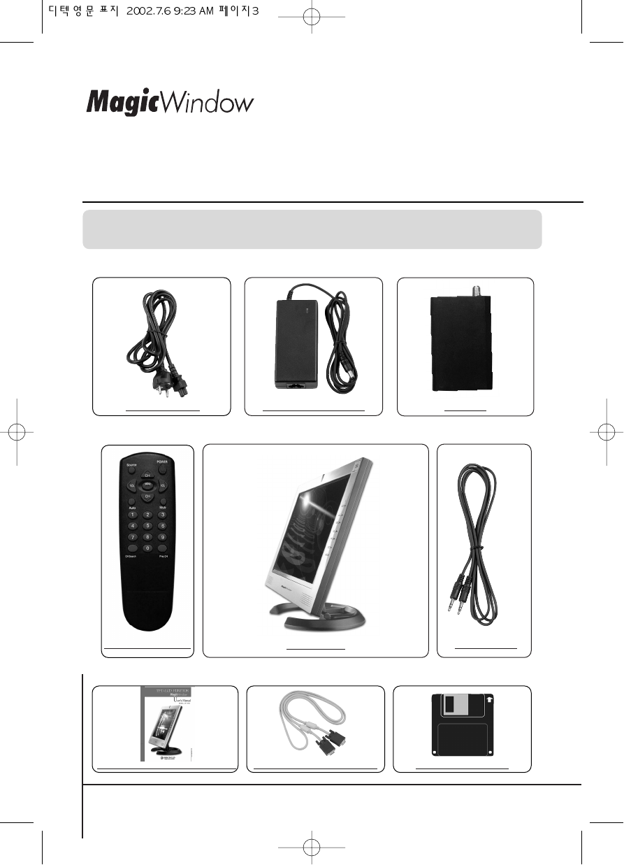
Please make sure the following items are included with your monitor.
If any items are missing, contact your local dealer or
gmstechnology
service center.
AC Power Cord AC/DC Power Adapter TV Tuner
LCD Monitor
Remocon / Battery Sound Cable
User's Manual/Warranty Card Installation Diskette15-pin D-SUB Signal Cable
www.gmstechnology .co.kr
Table of Contents
www.gmstechnology .co.kr 1 page
Safety Instructions 2
Connecting the Monitor 4
Monitor Driver Installation
ƒUAuto Installation 6
ƒUManual Installation 7
Front Panel 11
Easy Adjustment 12
Adjusting your LCD Monitor 13
Remote Controller 17
Product Features 18
Troubleshooting 19
Safety Precautions 22
Specifications 23
Display Modes 24
Standard Certification Logos 25
Warranty Card 27
ADJUSTMENT
APPENDIX
INSTALLATION
Safety Instructions
Before connecting the AC power cord to the DC adapter outlet, make sure the
voltage designation of the DC adapter corresponds to the local electrical supply.
Never insert anything metallic into the cabinet openings of the liquid cristal display
(LCD) monitor; doing so may create the danger of electric shock.
To avoid electric shock, never touch the inside of the LCD monitor. Only a qualified
technician should open the case of the LCD monitor.
Never use your LCD monitor if the power cord has been damaged. Do not allow
anything to rest on the power cord, and keep the cord away from areas where
people can trip over it.
Be sure to hold the plug, not the cord, when disconnecting the LCD monitor from
an electric socket.
Openings in the LCD monitor cabinet are provided for ventilation. To prevent
overheating, these openings should not be blocked or covered. Also, avoid using
the LCD monitor on a bed, sofa, rug, or other soft surface. Doing so may block the
ventilation openings in the bottom of the cabinet. If you put the LCD monitor in a
bookcase or some other enclosed space, be sure to provide adequate ventilation.
Put your LCD monitor in a location with low humidity and a minimum of dust.
Do not expose the LCD monitor to rain or use it near water (in kitchens, near
swimming pools, etc.). If the LCD monitor accidentally gets wet, unplug it and
contact an authorized dealer immediately. You can clean the LCD monitor with a
damp cloth when necessary, but be sure to unplug the LCD monitor first.
Place the LCD monitor on a solid surface and treat it carefully. The screen is made
of thin glass with a plastic front surface and can be damaged if dropped, hit or
scratched. Do not clean the front panel with keton-type materials (e.g., acetone),
ethyl alcohol, toluene, ethylacid, methyl, or chloride. These may damage the panel.
Locate your LCD monitor near an easily accessible AC outlet.
If your LCD monitor does not operate normally -in particular, if there are any
unusual sounds or smells coming from it -unplug it immediately and contact an
authorized dealer or service center.
INSTALLATION
www.gmstechnology .co.kr 2 page
INSTALLATION
www.gmstechnology .co.kr 3 page
1
2
3
4
5
6
7
8
9
10
11
High temperature can cause problems. Don't use your LCD monitor in direct
sunlight, and keep it away from heaters, stoves, fireplaces, and other sources of
heat.
Unplug the LCD monitor when it is going to be left unused for an extended period
of time.
Unplug your LCD monitor from the AC outlet before any service.
12
13
14
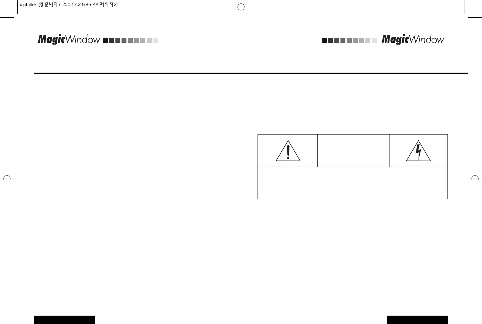
CAUTION
RISK OF ELECTRIC SHOCK
DO NOT OPEN
CAUTION: TO REDUCE THE RISK OF ELECTRIC SHOCK, DO NOT REMOVE COVER
(OR BACK).
NO USER-SERVICEABLE PARTS INSIDE.
REFER SERVICING TO QUALIFIED SERVICE PERSONNEL.
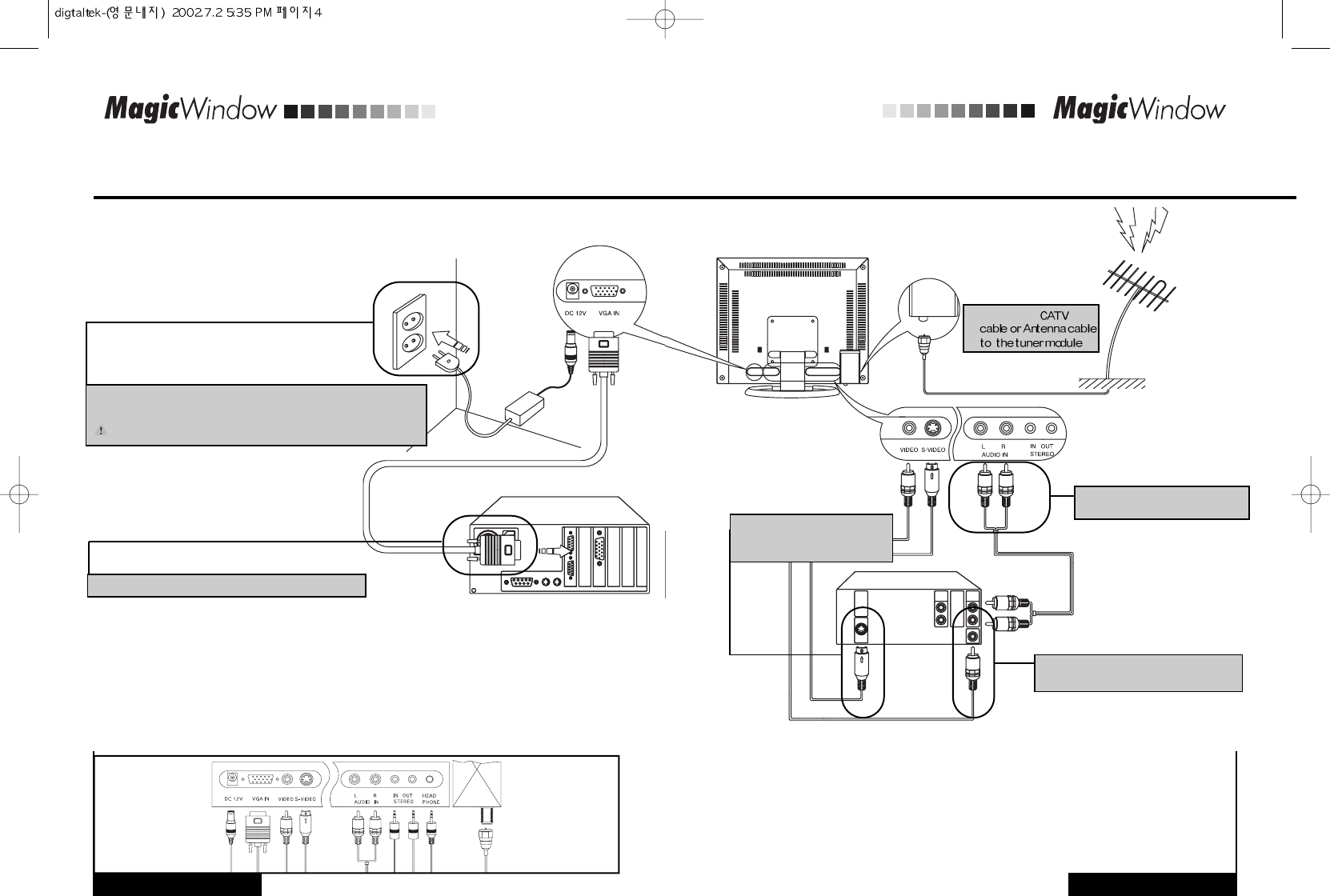
CONNECTING THE MONITOR
INSTALLATION INSTALLATION
Make sure that both the computer and the monitor are switched off before connecting.
2 Connect the signal cable to the computer and the monitor.
3Connect the sound cable to the
monitor and the video devices.
4Connect the video cable to the monitor
and the video devices.
1Connect the power cord to the AC/DC adapter and connect the
adapter plug to the DC power connector on the back of the monitor.
Caution) Make sure that you use supplied adapter only.
(Computer backside)
(VCR backside)
www.gmstechnology .co.kr 4 page
www.gmstechnology .co.kr 5 page
6Connect the
5 Connect the S-video cable to
the monitor and the video
devices.
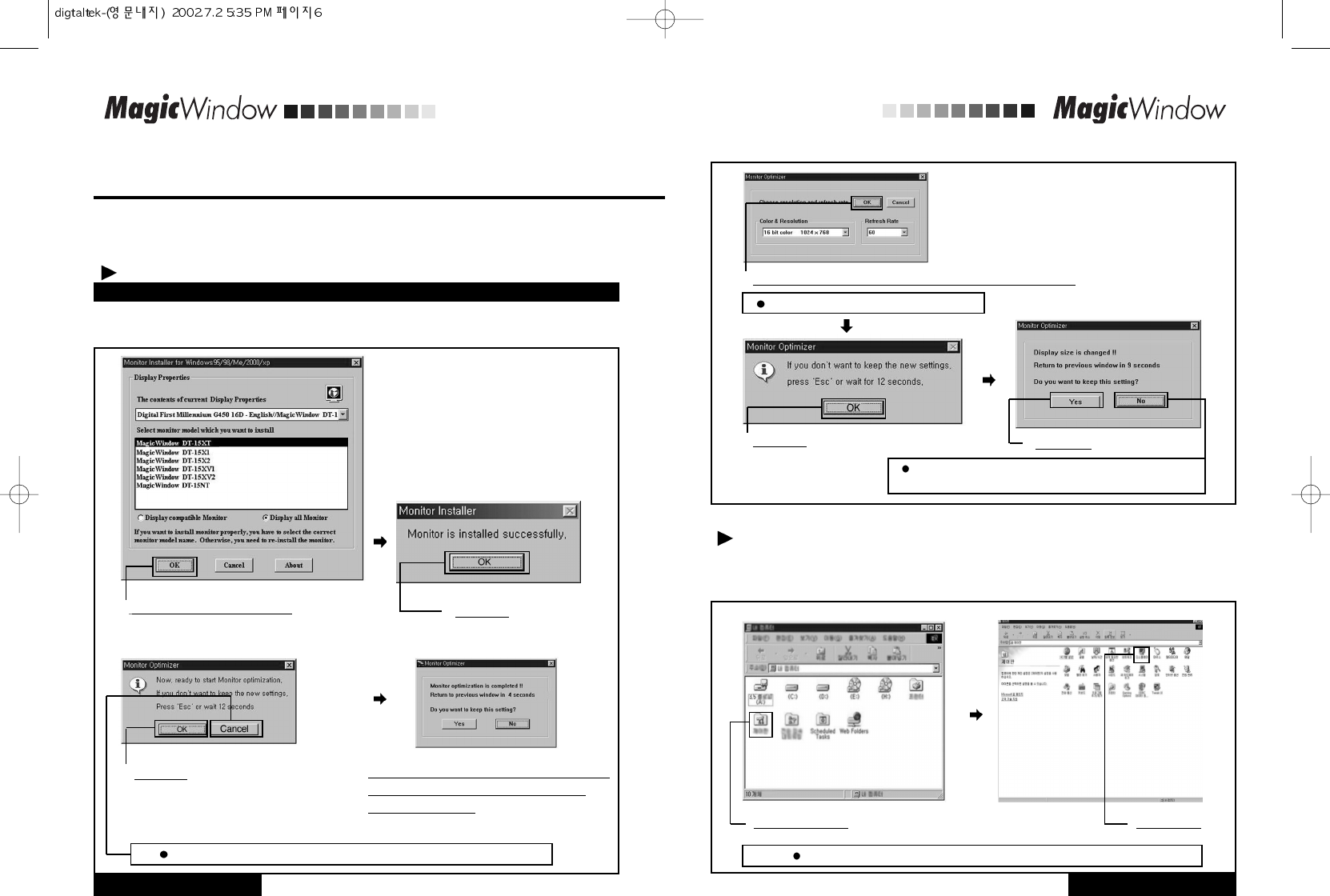
MONITOR DRIVER INSTALLATION
First, turn the computer and the monitor on and insert the installation disk into the floppy disk drive.
Click "Control panel" and then follow the steps given below.
1
Choose a model and click "OK"
4 If the screen performs normally after appearing
the monitor optimization mode, click "Yes"
Otherwise, click "No"
2Click "OK"
3 Click "OK"
5Adjust the resolution and vertical frequency and then click "OK"
6Click "OK" 7Click "Yes"
Manual Installation
If you do not want the monitor optimization function, click "Cancel"
This screen shot is for the mode reset.
Or click the right button on the mouse and then click "Properties"
If you want to change the resolution, click "No".
Repeat the above steps and set the optimal resolution.
First, turn the computer and the monitor on and insert the installation disk into the floppy disk drive.
Double click on "install.exe" and follow the steps below.
If you install the monitor driver, the resolution and frequency are suitable for the monitor and you can
experience the clear screen.
INSTALLATION
www.gmstechnology .co.kr 6 page
INSTALLATION
www.gmstechnology .co.kr 7 page
Auto Installation
If the installation does not work automatically, install the driver manually
1Click "Control panel" 2Click "Display"
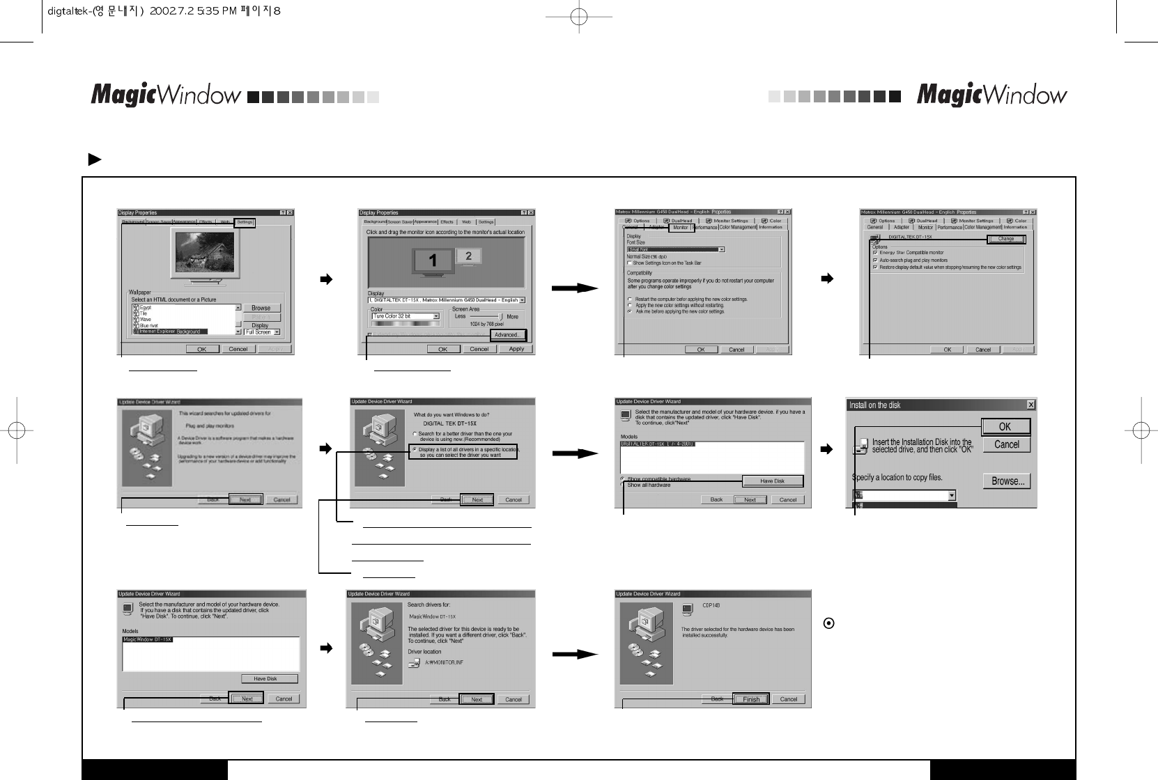
Manual Installation
3 Click "Settings" 4 Click "Advanced"
7 Click "Next"
12 Select model and click "Next" 13 Click "Next" 14 Click "Finish" and then reboot the Windows.
8 Click "Display a list of all the drivers in
a specific location, so you can select the
driver you want"
9 Click "Next"
10 Click "Have Disk" 11 Select the driver and click 'OK'.
5Click "Monitor" 6Click "Change.."
Driver installation has been completed.
INSTALLATION
www.gmstechnology .co.kr 8 page
INSTALLATION
www.gmstechnology .co.kr 9 page
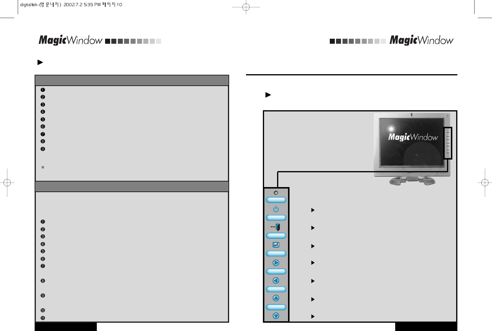
FRONT PANEL
If you perform auto adjustment in advance of manual adjustment when you install the monitor, the
screen appears more stable.
Manual Installation
INSTALLATION
www.gmstechnology .co.kr 10 page
ADJUSTMENT
www.gmstechnology .co.kr 11 page
Click "Start" button.
Select "Settings" tab and then click "Control Panel".
Double click "Display" icon.
Click "Settings" bar.
Click "All display modes".
Select a mode (resolution, colors, vertical frequency).
Click "OK".
Click "Test"
If the screen performs normally, click "Yes". Otherwise, select other mode (lower
resolution, colors and vertical frequency).
Note:If"Alldisplaymodes"doesnotexistonyourWidowsNT,refertoStandardSignalModes
inthismanualandselectaresolutionandverticalfrequency.
To command X-Window, you have to create a system file that called XF86Config file.
You can set your monitor with the file.
If you command XF86Config, the file can be created.
Command XF86Config and then press enter key when the first and second screen appear.
In the third screen, you can find mouse settings.
Select your mouse.
Next, Keyboard setting screen appears.
Select your keyboard.
Monitor setting screen appears.
First, you have to set the horizontal frequency. Refer to Horizontal Frequency in this
manual and select one of them. (You can input the frequency directly as well).
You have to set the vertical frequency. Refer to Vertical Frequency in this manual and
select one of them. (You can input the frequency directly as well)
Enter the model name of your monitor.
Monitor information you entered here is not directly related to commanding X-Window.
Monitor setting has been completed.
Complete other hardware settings and command X-Window.
IF YOU HAVE WINDOWS NT..
IF YOU HAVE LINUX..
Basic functions of the buttons
Power Turns ON/OFF the monitor.
Menu Opens the main OSD menu, and exits from main menu or
sub-menu.
Select Selects the highlighted function.
Left Moves the selector left on the OSD or decreases the
values of the selected function.
Right Moves the selector right on the OSD or increases the
values of the selected function.
Up Moves the selector up on the OSD.
Down Moves the selector down on the OSD.
KEY PC MODE
1. SELECT
2. RIGHT
3. LEFT
4. UP
5. DOWN
TV MODE
COMPOSITE MODE S-VIDEO MODE
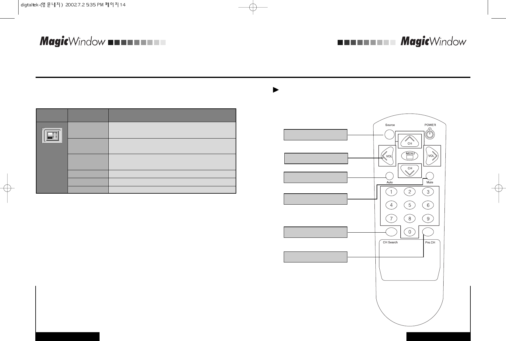
Performs the mode selection function (PC/COMPOSITE/S-VIDEO/TV) or
if you keep in pressing this button, performs auto screen adjustment function.
Displays brightness adjustment menu
Displays contrast adjustment menu
Performs sound mute on / off
Displays audio volume adjustment menu
Increases Channel
Decreases Channel
ADJUSTMENT
www.gmstechnology .co.kr 12 page
ADJUSTMENT
Easy Adjustment(Hot Key)
www.gmstechnology .co.kr 13 page
Adjusting Your LCD Monitor
1.
PC/COMPOSITE/S-VIDEO MODE
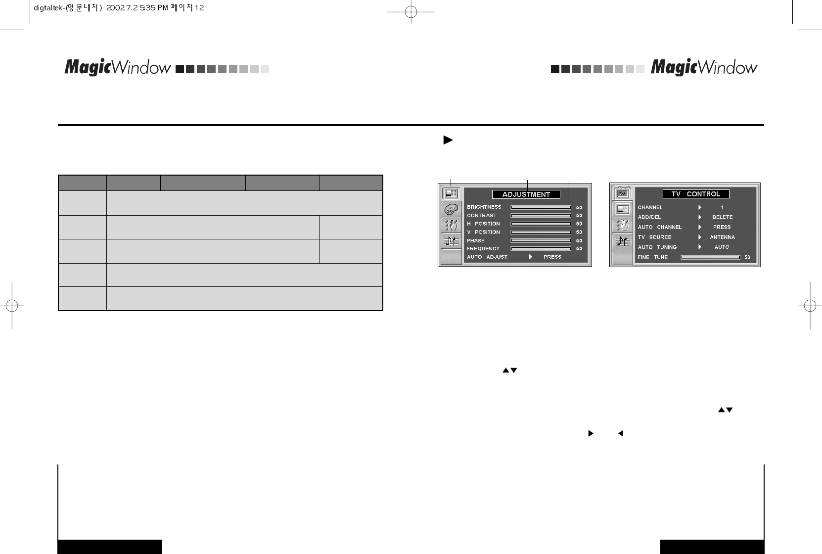
ON-Screen Display(OSD)
2.
TV MODE
Function icons Setting bar
Function name
With the OSD off, push the Menu button to display the main OSD menu.
Use the " " buttons to move from one function to another. As you move from
one icon to another, the function name changes to reflect the function or group of
functions represented by that icon. See Table 1 starting on the next page to view a
complete list of all of the functions available for the monitor.
Press the Select button once to activate the highlighted function, use the " "
buttons to select the function.
After selecting a function, use the " " and " " buttons to make necessary adjustments.
The setting bar moves and the numeric value indicator changes to reflect your
adjustments.
NOTE: The numeric value indicator is provided as a point of reference only and has
nothing to do with a real measurement.
Push the Menu button a couple of times to return to the main menu to select another
function or to exit from the OSD.
1
2
3
4
5
Accessing the menu system
On-Screen Display(OSD)
Adjusting Your LCD Monitor
ADJUSTMENT
www.gmstechnology .co.kr 14 page
Adjusting Your LCD Monitor
ADJUSTMENT
www.gmstechnology .co.kr 15 page
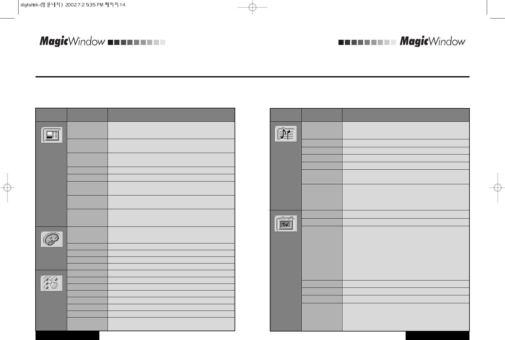
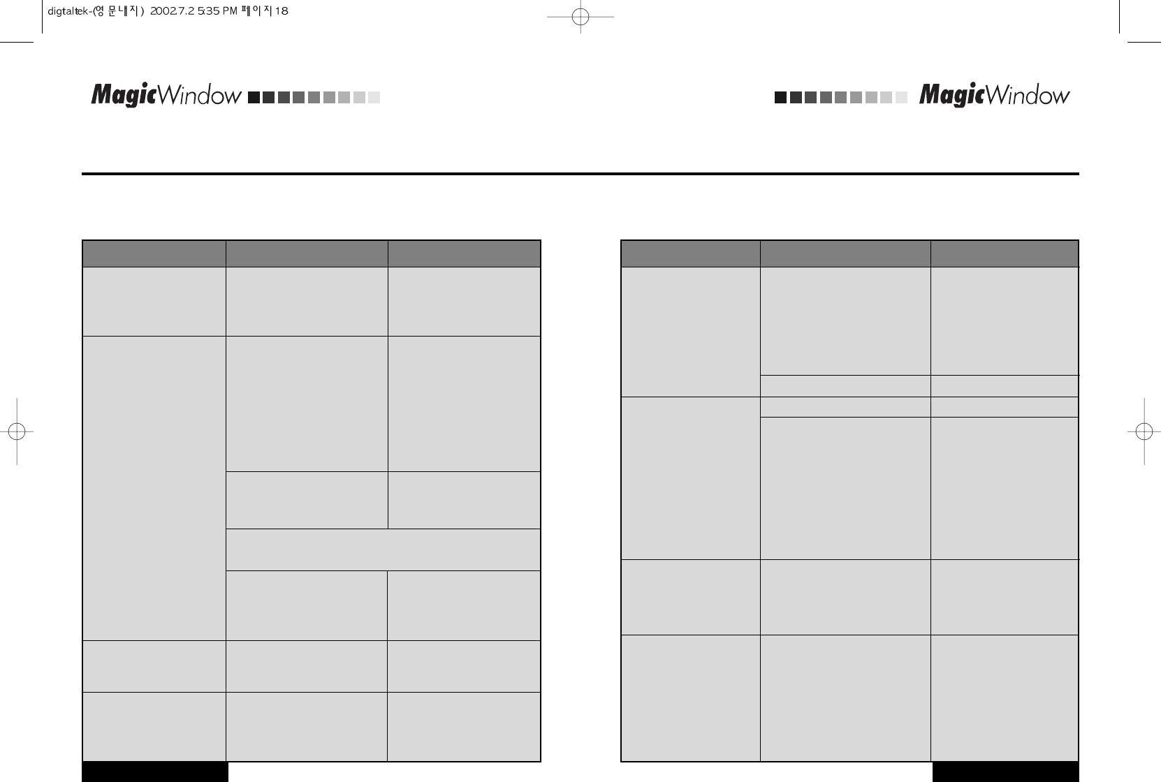
OSD functions and adjustment
Table 1. Screen controls
Icon Menus and
Sub-menus Function Descriptions
Adjustment is used to fine tune and get the best image
by removing noises that creates unstable images with
jitters and shimmers.
Adjust the brightness of video or TV without affecting
PC RGB's brightness.
Adjust the contrast of video or TV without affecting PC
RGB's contrast.
Adjust the horizontal position of the image.
Adjust the vertical position of the image.
Remove the noises. When phase value is wrong,
the image has vertical lines especially in 1 dot on and off.
Remove the noises. When frequency value is wrong,
the image has horizontal lines especially in 1 dot on and off.
"Auto adjustment" allows the monitor to self-adjust to the
incoming video signal. The values of phase, frequency
and position are adjusted automatically.
The tone of color can be changed from redish white to
bluish white. The individual color components are also
user customizable.
Redish white.
Plain white.
Bluish white.
User customizable.
Setup is used to adjust OSD menu information
Move the OSD Window to the horizontal direction.
Move the OSD Window to the vertical direction.
English, German, France, Italian, Spanish.
Change the opaqueness of the background of the OSD.
Changes the image size in several different ways.
The number of seconds that the OSD will remain
visible before disappearing.
Adjustment
Brightness
Contrast
H Position
V Position
Phase
Frequency
Auto Adjust
Color
6500° K
7300° K
9300° K
User
Setup
OSD H pos
OSD V pos
Language
Transparency
Scaling
Menus and
Sub-menus
Display current display mode.
Information
Table 1. Screen controls (Continued)
Icon Menus and
Sub-menus Function Descriptions
The monitor has a built-in high fidelity stereo audio amplifier.
The audio circuit processes audio signal from various external
input sources such as DVD, VCR, TV or PC.
Selects a sound source from PC, DVD, VCR or TV.
Adjust the sound volume
Mutes the sound temporarily.
Mute is released when you adjust volume.
Stereo : Process stereo sound if available.
Mono : Process sound as mono. For stereo sound left and
right channels are merged to be processed as mono.
Bilingual : Select the language you want to hear.
In rare cases, "Channel auto program" may miss a couple of
channels due to weak signals or for other reasons such as
a channel does not exist when "Channel auto program" is
executed. To add a newly found channel or remove a channel,
please follow the steps described below.
Push Menu button and then select "Add/Del" under "TV
Control" menu. Select "Add" to add the channel or select
"Del" to remove the channel.
Search the channel
Antenna/Cable
Due to weak signals or a wrong antenna configuration, some
of the channels may not be tuned correctly.
Select "Fine Tune" under TV Control menu to make the video
image as clear as possible.
Audio Control
Source
Volume
Mute
Sound
Add/Del
Auto Channel
TV Source
Fine Tune
Select Tuning ways - Auto or Manual.
Auto Tuning
Emphasize low frequency audio.
Bass
The channel system can be set in several different ways.
TV Control
Changes the incoming channel.
Channel
Emphasize high frequency audio.
Treble
12
www.gmstechnology .co.kr 16 page
APPENDIX
www.gmstechnology .co.kr 17 page
ADJUSTMENT
Adjusting Your LCD Monitor
Table 1. Screen controls (Continued)
Icon Menus and
Sub-menus Function Descriptions
This function is active if you select an input source
other than PC. (DVD, VCR, TV)
Adjustment
Adjust the brightness of video or TV without affecting
PC RGB's brightness.
Brightness
Adjust the contrast of video or TV without affecting PC
RGB's contrast.
Contrast
Change the richness of color.
Color
Change the tone of color.
Tint
Adjust the sharpness of video or TV image.
Sharpness
APPENDIX
Source Search
Channel & Volume
Auto Adjustment
Audio Mute
Channel Search
Previous Channel
Remote Controller
This product has been approved for non-business purposes and may be used in any
environment, including residential areas. (Class A devices are for business
purposes and Class B devices radiate less radio frequency than Class A devices)
Display Power Manager Signaling (DPMS)
Power management circuit signaled by the computer system, will reduce power
consumption when the computer system is not in use. The power management
feature requires that the video card of the computer should support DPMS function.
General CRT monitors consume 100W but LCD monitors consume 30W. An
advantage of this monitor is the lowest consumption. This monitor meet the VESA
standard.
This monitor is equipped with a control board for LCD monitor only that performs the
best color display and has simple and easy options. Simple design produces a
clean and tidy space.
This monitor is designed to be compatible with any PC configuration. You do not
need to substitute hardware or purchase specific software. You only need to
connect the signal cable of old CRT monitor.
Radio Frequency Compatibility Registration (Class B digital device)
Power Saving Feature
Simple Design
Other Feature
APPENDIX
APPENDIX
www.gmstechnology .co.kr 19 page
APPENDIX
www.gmstechnology .co.kr 18 page
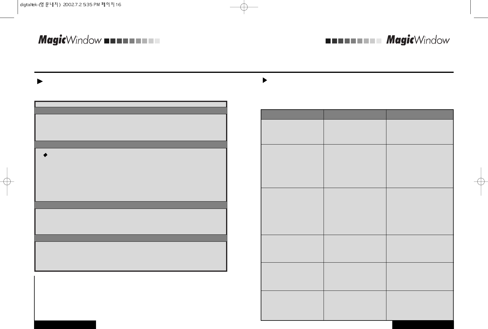
If you have a problem setting up or using your LCD monitor, you may be able to solve it yourself.
Before contacting customer service, try the suggested actions that are appropriate to your problem.
Table 2. Troubleshooting - Image
Problem Suggested Actions Reference
Ensure that the power cord is
firmly connected and the LCD
monitor is on.
Screen is blank and
power indicator is off
Troubleshooting
Connecting the
monitor, page 4 - 5.
Ensure that the signal cable is
firmly connected to the PC or
video sources.
Ensure that the PC or video
sources are turned on.
"Check Signal Cable"message Connecting the
monitor, page 4 - 5.
Check the maximum resolution
and the frequency of the video
adaptor.
Compare these values with the
data in the Display Modes
Timing Chart.
"Out of Range"message Display Modes, page 24.
Adjust the Brightness and
Contrast.
The image is too light
or too dark
Brightness, page 14, 16.
Contrast, page 14, 16.
Adjust the Phase function.
Horizontal bars appear
to flicker, jitter or shimmer
on the image Adjustment, phase, page 14.
Adjust the Frequency function
and then adjust the Phase
function.
Vertical bars appear to
flicker, jitter or shimmer
on the image.
Adjustment, Frequency, phase,
page 14.
Product Features
APPENDIX
APPENDIX
APPENDIX
www.gmstechnology .co.kr 20 page
Table 2. Troubleshooting - Image (Continued)
Problem Suggested Actions Reference
The monitor is using its power
management system.
Move the computer's mouse or
press a key on the keyboard
Screen is blank and
power indicator light is
steady amber or blinks
every 0.5 or 1 seconds
Power Saving Feature, page 18.
Check that the display resolution
and frequency from your PC or
video board is an available mode
for your monitor.
On your computer check: Control
Panel, Display, Settings
Image is not stable and
may appear to vibrate
Display Modes, page 24.
If the setting is not correct, use
your computer utility program to
change the display settings.
Monitor Driver Installation,
page 6 - 10.
NOTE: Your monitor supports multiscan display functions within
the following frequency domain:
Horizontal frequency:
Vertical frequency:
Maximum refresh rate:
30 kHz - 61 kHz
56 Hz - 75 Hz
1024 x 768 @ 75 Hz
Download the driver from WWW
pages:
http://www.digitaltek.co.kr
You need the monitor
driver software
Adjust the horizontal and
vertical position.
Image is not centered
on the screen. H Position, page 14.
V Position, page 14.
APPENDIX
www.gmstechnology .co.kr 21 page
APPENDIX
Table 2. Troubleshooting - Audio and TV
Problem Suggested Actions Reference
Ensure that the audio cable is firmly
connected to both the audio-in port
on your monitor and the audio-out
port on your sound card.
No sound
Connecting the
Monitor, page 4 - 5.
Check the volume level
Sound level is too low
Audio Control, page 15.
Check the volume level Audio Control, page 15.
If the volume is still too low after
turning the control to its maximum,
check the volume control on the
computer sound card or software
program.
Refer to your computer,
sound card or software
documentation.
Check "Channel system" and make
sure you choose the correct channel
system.
Select "Channel auto program" to
configure the channel system
automatically.
TV signal is not received Broadcasting systems, page 24.
Adjust the Treble and Bass to
appropriate level.
Sound is too high pitched or
too low pitched Audio Control, page 15.
APPENDIX
Table 3. Technical and environmental specifications
DT-15NT
Size
Display Size
Type
Pixel pitch
Viewing Angle
Panel
15.0" Diagonal
304.1 (H) x 228.1 (V) mm
a-si TFT active matrix
0.297 (H) x 0.297 (V) mm
70/70/60/60 (L/R/U/D)
(Depending on the panel manufacturer, the viewing
angle may be different from this spec.)
Specifications
Horizontal
Vertical
Display color
Frequency
30 - 61 kHz (Automatic)
56 - 75 Hz (Automatic)
16,777,216 colors
Optimum Mode
Maximum Mode
Display
Resolution 1024 x 768 @ 60 Hz
1024 x 768 @ 75 Hz
Sync.
Video signal
Input Signal
H/V Separate, TTL, P. or N.
H/V Composite, TTL, P. or N.
Sync-on-green 0.3 Vp-p, N.
0.7 Vp-p @ 75 ohm
Color system
Sound system
Video format
TV, Video
NTSC or PAL
M/N
CVBS, S-VHS
AC
Adapter
Power AC 100-240 Vrms (50 ~ 60Hz )
DC 12V/3A
Maximum
Power Saving
Power
Consumption 38 W
8 W
Operating Temperature
Operating Humidity
Storage Temperature
Storage Humidity
Environmental
Considerations
50 ° F to 104 ° F (10 °C to 40 °C)
10% to 80%
13 ° F to 113 ° F (-25 °C to 45 °C)
5% to 95%
Audio Input 1
Audio Input 2
Line-out
(Audio out)
Headphone out
Frequency
Response
Audio
Characteristics
RCA Jack Red(R) White(L), 0.5Vrms (-9dB)
3.5 Stereo Jack, 0.7Vrms (-7dB)
3.5 Stereo Jack, 0.7Vrms (-7dB)
Max 10mW Output (3.5 Stereo Jack 32 )
RF: 80Hz - 15KHz (at- 3dB)
A/V: 80Hz - 20KHz (at - 3dB)
APPENDIX
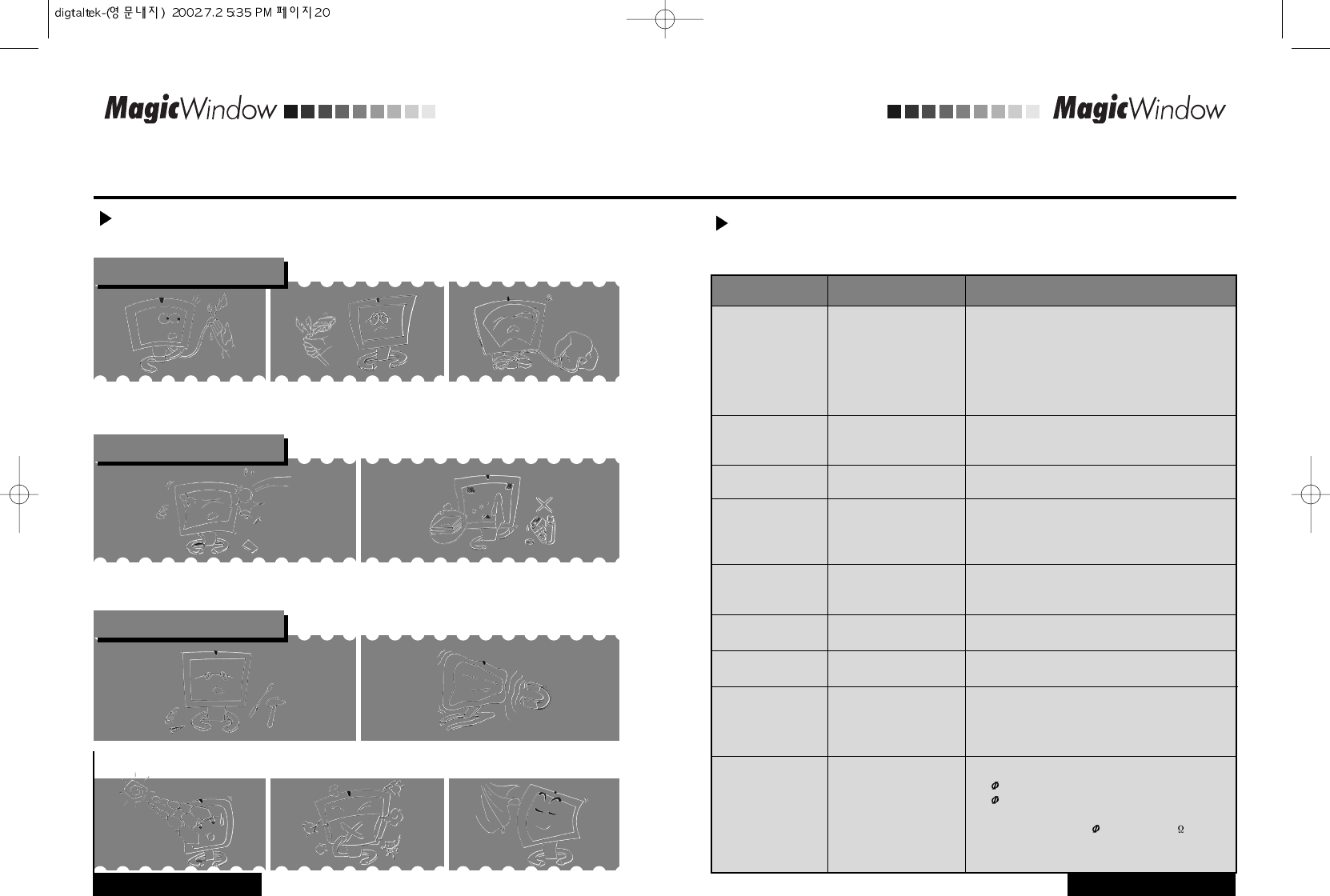
The following information is to prevent damages and secure user's safety.
Please read the following information carefully and use the monitor properly.
Power
2. Never disconnect it by pulling
the cord.
¡Doing so may create a danger of
electric shock or fire.
1. Never hit the monitor or scratch the monitor with
sharp materials.
¡Doing so may damage the monitor
or a danger of electric shock.
2. Unplug the monitor and Use a damp, lint-free cloth
for cleaning. Do not use keton-type materials, ethyl
alcohol, acid, toluene, ethyl acid, methyl or
chloride.
¡Doing so may create a danger of electric shock or fire.
1. Never touch the inside of the monitor.
¡If you need a service, contact the service center.
When you store the monitor, keep the monitor away from direct sunlight and dust.
2. Keep the monitor away from anything magnetic.
¡Noise may appears on the screen.
1.Do not hold the plug with your
hands wet.
¡Doing so may create a danger of
electric shock or fire.
APPENDIX
www.gmstechnology .co.kr 22 page
Other precautions
3.Do not force to bend the cord or
put any heavy materials on the
cord.
¡Doing so may create a danger of
electric shock or fire.
Cleaning
APPENDIX
www.gmstechnology .co.kr 23 page
Safety Precautions
The MIC certification of telecommunication devices is compulsory certification, pursuant to Article
33 of Framework Act on Telecommunications and Article 46 and 57 of Radio Wave Act. Complied
with Article 3 of Telecommunication Devices Certification Regulation, any natural or juridical
person who manufactures, imports, or sells telecommunication devices has to get the applicable
certification for the devices, attach the related logo and distribute the devices. The reason MIC
enacts and applies the standard regulations for telecommunication devices is for reducing the
following matters to a minimum and protecting radio environment in Korea; undesired radio
frequency energy caused by the devices, harmful interference to radio communications caused
by the other devices or external radio, and injury or damage caused by undesired operation.
Classification: Integrated Standard Certification Logo of EU, Compulsory Standard
Governing organization: EOTC (European Organization for Testing and Certification)
Major target items: toys, gas fittings, machinery, radio conformity, telecommunication terminals,
non-automatic scale, private safeguards, and etc.
Classification: US Safety Standard, Voluntary Standard (Compulsory Standard in
several provinces)
Governing organization: Underwriters Laboratories Inc.
Major target items: 1,400 items including electronic/electric equipments and accessories,
machinery, fire extinguishers, protections against burglars, and etc.
Classification: US Radio Telecommunication Standard, Compulsory Standard.
Governing organization: Federal Communications Commission
Major target items: wireless phones, lifesaving equipments, high-frequency equipments for
industrial/scientific/medical purposes, personal computers/peripherals, and etc.
This equipment has been tested and found to comply with the limits for a Class B digital device,
pursuant to part 15 of the FCC Rules. These limits are designed to pro-vide reasonable
protection against harmful interference in a residential installation. This equipment generates,
uses and can radiate radio frequency energy and, if not in- stalled and used in accordance with
the instructions, may cause harmful interference to radio communications. However, there is no
guarantee that interference will not occur in a particular installation. If this equipment does cause
harmful interference to radio or television reception, which can be determined by turning the
equipment off and on, the user is encouraged to try to correct the interference by one or more of
the following measures: -Reorient or relocate the receiving antenna. -Increase the separation
between the equipment and receiver. -Connect the equipment into an outlet on a circuit different
from that to which the receiver is connected. -Consult the dealer or an experienced radio/TV
technician for help.
MIC Logo
CE Logo
UL Listed Logo
FCC Logo & ID NO
NOTE
APPENDIX
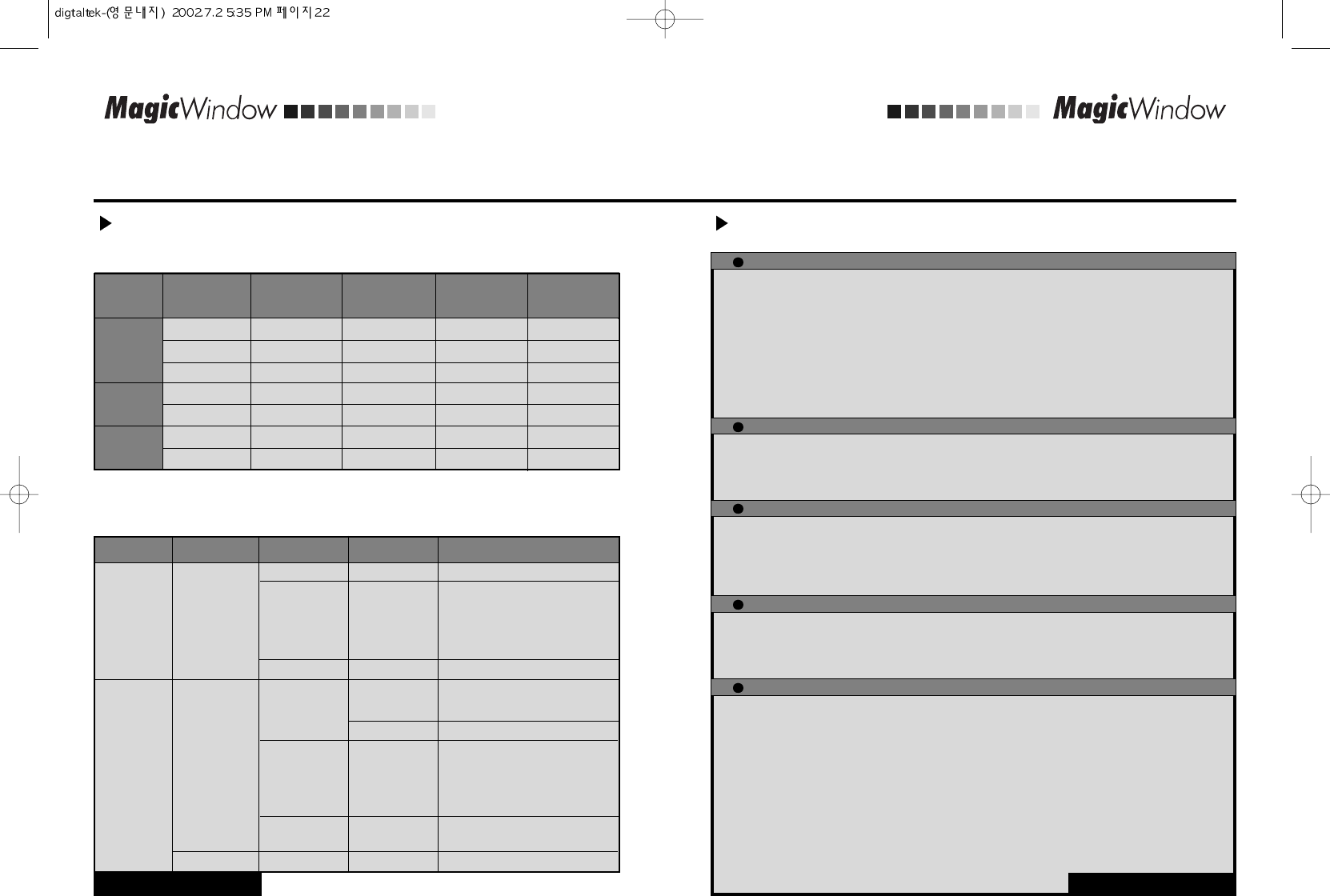
Table 4. Preset timing modes
Mode Resolution Vertical
Frequency(Hz)
Display Modes
VGA
Pixel Clock
Frequency(MHz)
Sync Polarity
(H/V)
Horizontal
Frequency(kHz)
SVGA
XGA
720 x 400 31.469 70.087 28.322 -/+
640 x 480 31.469 59.940 25.175 -/-
640 x 480 37.500 75.000 31.500 -/-
800 x 600 37.880 60.300 40.000 +/+
800 x 600 46.875 75.000 49.500 +/+
1024 x 768 48.363 60.004 65.000 -/-
1024 x 768 60.023 75.029 78.750 +/+
Table 5. Broadcasting Systems
Color System Sound System Channel System
NTSC
Countries
Stereo System
PAL
USA, Canada, Chile,
Venezuela, Cuba, Colombia,
Jamaica, Mexico, Panama, Peru,
Philippines, Puerto-Rico, Taiwan
USBTSC (SAP)
M
A2 US Korea
EIAJ Japan Japan
A2
NICAM
CCIR
AUSTRALIA
B/G
Germany, Austria, Swiss,
Netherlands
CCIR
Sweden, Spain, Denmark,
Norway, Finland, Belgium,
Iceland, Portugal, Malaysia,
Singapore, Thailand
Australia
I NICAM CCIR UK, Hongkong
Unknown CCIR India, Israel, Kuwait, Jordan,
Yugoslavia
For the display modes listed below, the screen image has been optimized during manufacture.
APPENDIX
APPENDIX
www.gmstechnology .co.kr 24 page
APPENDIX
www.gmstechnology .co.kr 25 page
Standard Certification Logos
Following Table explains general international broadcasting systems. If your product is not correspond
this table, it can operate abnormally. Then please contact sales department or custom satisfaction
center.
PRODUCT WARRANTY CARD
Model Serial No.
DT-15NT
The warranty period of the products is ONE YEAR.
Type of purchaser's damage
Repairs are needed within 10 days from the purchase date.
Repairs are needed within 1 month from the purchase date.
Damage is occurred during the installation and transportation
at the purchase date.
Repairs are needed for newly replaced product within 1 month
from the replaced date.
Replacement is impossible
Same defects are occurred up to 3 times.
Same defects are occurred up to 4 times.
Diverse defects are occurred up to 5 times.
GMS TECHNOLOGY
loses the product delivered for
repairing from the purchaser.
Repairs are impossible because
GMS TECHNOLOGY
does not
maintain the repair parts within the parts maintenance period.
GMS TECHNOLOGY
maintains the repair parts but repairs
are impossible.
Repairs are impossible.
Repairs are possible.
Product replacement or full
refund.
Product replacement
Full refund.
Free Repairs
Product replacement or full
refund.
Product replacement after
collecting the cost for
charged repairs.
Charged repairs
Product replacement or full
refund.
N/A
Charged repairs
Charged repairs
Charged repairs
Refund after deducting the
depreciation cost and
adding 10% purchase
price.
Refund after deducting the
depreciation cost.
Limited to the extra criteria
of
GMS TECHNOLOGY
Charged repairs
Troubles caused
by the defects of
performance
and function
under the
normal usage.
Troubles caused by
purchaser's
intention or
negligence
Warranty Details
Warranty period Outof Warranty period
Free Service
In the event that the general products have used for the business purpose,
warranty period will be cut and applied to six months.
Charged Service
If you call the service without following the troubleshooting in the manual, you may pay the service charge.
Please read the manual carefully.
Troubles caused by purchaser's negligence
Troubles caused by purchaser's faulty repairs and lack of reasonable care.
Troubles caused by usage of wrong supply/voltage
Troubles and damages caused by dropping of product in transportation after the installation.
Troubles caused by usage of any parts not provided with the product.
Troubles caused by other reasons.
Troubles caused by acts of God (fire, damage from salt, flood, and etc.).
GMS TECHNOLOGY warrants its products to be free for ONE YEAR from the original purchasing date.
Purchaser's Name
Address
Purchased Date
Purchased agency