GN Audio USA GN9300 GN9300 900 MHz User Manual
GN Netcom Inc GN9300 900 MHz
user manual
For more information and technical
specifications see Guide for additional
functions:
• Additional settings via the LCD display
• Conference calls
• Wearing styles
• Audio/visual indicators
• Trouble shooting
• GN 1000 remote handset lifter
• Installation on phones with
headset port
Pour plus d`information et
specifications techniques voir Guide
des fonctions additionelles:
• Réglages complémentaires via
l’afficheur LCD
• Conférence téléphonique
• Comment porter le micro-casque
• Indicateurs sonores et voyants
• Dépannage
• Levier de décroché à distance GN 1000
• Installation sur les téléphones dotés
d’un connecteur “micro-casque”
Para más informacíon y especifica-
ciones técnicas, consulte la Guía
adicionales:
• Opciones adicionales disponibles en la
pantalla LCD
• Llamadas de conferencia
• Modelos de sujeción
• Indicadores de audio y visuales
• Solución de problemas
• Descolgador remoto GN 1000
• Instalación en teléfonos con puerto para
microcasco
81-00105 A ©2005 GN Netcom • All rights reserved.
www.gnnetcom.com
GN Netcom (UK) Ltd.
Sales office
Runnymede House
96/97 High Street, Egham
Surrey TW20 9HG
United Kingdom
Tel: + 44 (0) 1784 220140
Fax: + 44 (0) 1784 220141
www.gnnetcom.com
GN Netcom S.A.
Parc d’Activités du Pas du Lac
10, Avenue Ampère
78180 Montigny le Bretonneux
France
Tel: +33 1 30 58 30 31
Fax: +33 1 30 45 22 75
www.gnnetcom.fr
GN Netcom Ibérica S.A
Avda. de España, 97 - 13
28230 Las Rozas (Madrid)
Spain
Tel: +34 91 639 80 64
Fax: +34 91 638 90 71
www.gnnetcom.es
GN Netcom, Inc.
77 Northeastern Boulevard
Nashua, NH 03062
USA
Tel: (800) 826 4656
Tel: +1 603 598 1100
Fax: +1 603 598 1122
www.gnnetcom.com/US/EN
GN Netcom, Inc.
77 Northeastern Boulevard
Nashua, NH 03062
USA
Tel: (800) 826 4656
Tel: +1 603 598 1100
Fax: +1 603 598 1122
www.gnnetcom.com/US/EN
GN Netcom, Inc.
77 Northeastern Boulevard
Nashua, NH 03062
USA
Tel: (800) 826 4656
Tel: +1 603 598 1100
Fax: +1 603 598 1122
www.gnnetcom.com/US/EN
Page 1
Page 16
GN 9350
English Guide for basic set-up and use
Français Guide d’installation et d’utilisation abrégé
Español Guía de configuración y uso básicos
'
,
*
+
)
-
(
'&
/
.
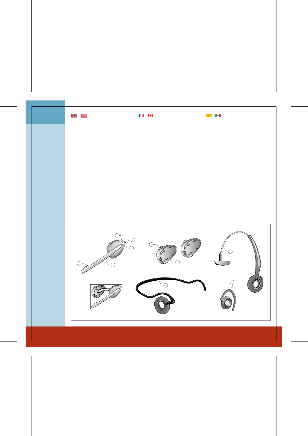
Overview headset
1
Description micro-casque
[1] Micro
[2] Perche micro (télescopique)
[3] Voyant “en ligne”
[4] Réglage volume et fonction Secret
[5] Touche Conversation
[6] Ecouteur
[7] Batterie supplémentaire
[8] Serre-tête
[9] Contour d’oreille
[10] Contour de nuque
Note : vous trouverez une description
détaillée des boutons et des fonctions
dans le Guide des fonctions additionnelles,
chapitre 7.
Overview headset
[1] Microphone
[2] Boom arm (extendable)
[3] Link indicator
[4] Volume control with mute switch
[5] Talk button
[6] Speaker
[7] Battery pack, extra
[8] Headband
[9] Earhook
[10] Neckband
Note: for detailed information about but-
tons and functions, please see Guide for
additional functions chapter 7.
Descripción del microcasco
[1] Micrófono
[2] Varilla (extensible)
[3] Indicador de conexión
[4] Control del volumen y conmutador
de silencio “mute”
[5] Botón de conversación
[6] Receptor
[7] Paquete adicional de baterías
[8] Diadema
[9] Gancho para la oreja
[10] Sujeción en el cuello
Nota: para obtener más información sobre
botones y funciones, consulte el capítulo 7
de la Guía de funciones adicionales.
| English | Français | Español
Descripción microcasco
Description micro-casque
Page 2
Page 3
11
31 30
29
24
26 27
28
25
12
17 19
1
3
16 21
20
18
23
22
14
15
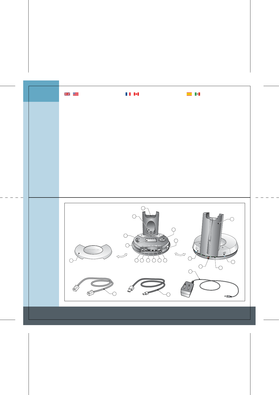
Overview base Description de la base Descripción de la base
2
Description de la base
[11] Couvercle
[12] Berceau de charge du micro-casque
[13] Chargeur supplémentaire
[14] Réglage de la tonalité
[15] Afficheur LCD
[16] Port cordon téléphonique
[17] Port combiné
[18] Port adaptateur secteur
[19] Port USB
[20] Port indicateur “en ligne” (OLI)
[21] Port AUX
[22] Touche de couplage
[23] Menu de l’afficheur LCD
[24] Chargeur batterie
[25] Touche mode USB (avec voyant).
[26] Voyant Secret
[27] Voyant de batterie (4 diodes)
[28] Touche mode Téléphone (avec voyant)
[29] Cordon adaptateur secteur
[30] Cordon USB
[31] Cordon téléphonique
Descripión de la ase
[11] Base
[12] Cargador del microcasco
[13] Cargador para batería adicional
[14] Regulador de tono
[15] Pantalla LCD
[16] Puerto del cable del teléfono
[17] Puerto del microteléfono
[18] Toma alimentador
[19] Puerto USB
[20] Puerto de indicador de “en línea” (OLI)
[21] Puerto auxiliar para descolgador GN 1000
[22] Botón de emparejamiento
[23] Control de pantalla LCD
[24] Torre de carga
[25] Botón de modo USB (con indicador)
[26] Indicador de silencio “mute”
[27] Indicador de batería (4 diodos)
[28] Botón de modo telefónico (con indicador)
[29] Cable de alimentación de CA
[30] Cable del conector USB
[31] Cable de teléfono
Overview base
[11] Base cover
[12] Headset charge facility
[13] Extra battery charge facility
[14] Clear dial tone switch
[15] LCD display
[16] Telephone cord port
[17] Handset port
[18] A/C power adapter port
[19] USB port
[20] Online indicator port (OLI)
[21] AUX port
[22] Pairing button
[23] LCD display control
[24] Charge tower
[25] USB mode button (with indicator)
[26] Mute indicator
[27] Battery indicator (4 diodes)
[28] Telephone mode button (with indicator)
[29] A/C power cord
[30] USB connector cord
[31] Telephone cord
| English | Français | Español
Page 4
Page 5
3.1
3.2
3.3
3.4-3.5
3.6-3.7
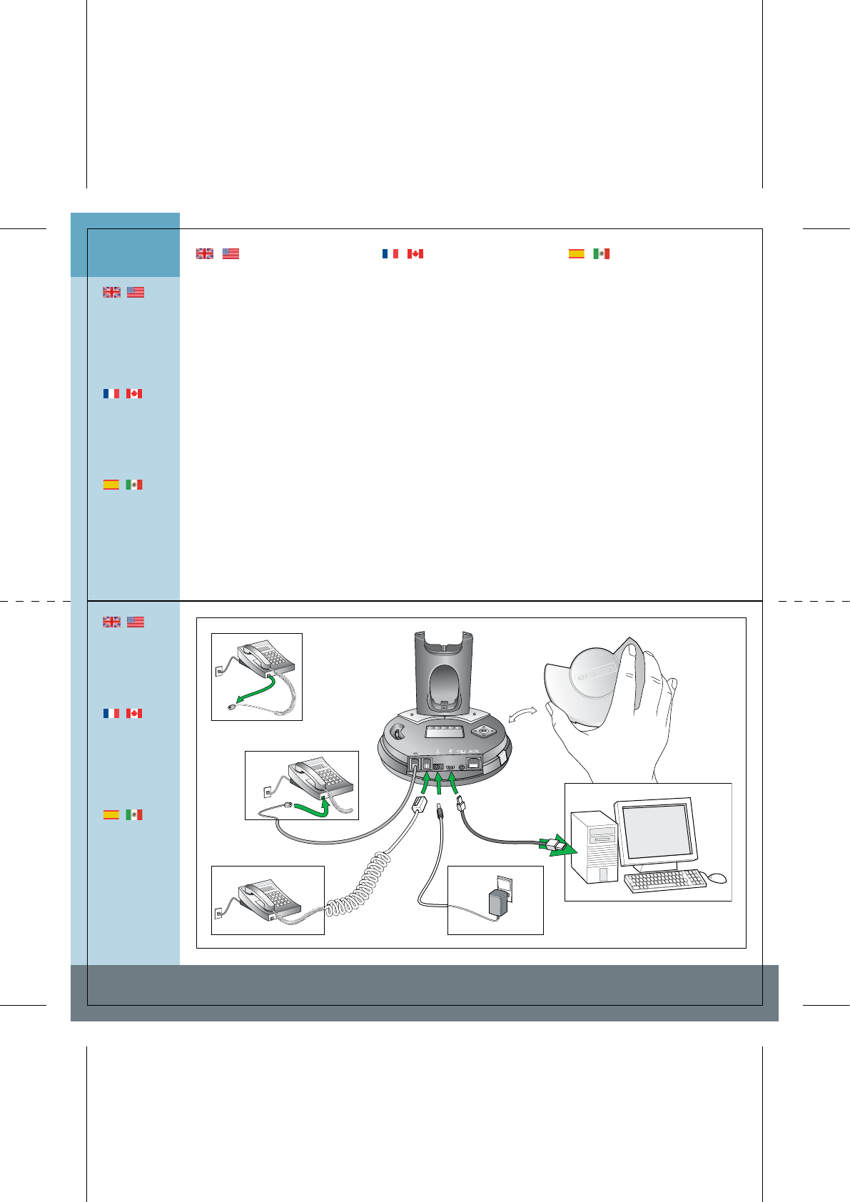
Setting up Installation Configuración
|
If your telephone
has a separate
headset port,
please refer to
the “Guide for ad-
ditional functions”
for setting up and
using this port.
|
Si votre téléphone
possède un
connecteur
micro-casque,
consultez le Guide
des fonctions
additionnelles.
|
Si su teléfono dis-
pone de un puerto
para microcascos
independiente,
consulte la ”Guía
de funciones
adicionales” para
configurar utilizar
este puerto.
3
|
See Guide for
additional func-
tions for setting
up with remote
handset lifter
functionality and
an external OLI.
|
Voir Guide des
fonctions addi-
tionnelles pour
l’installation avec
le levier de dé-
croché à distance
et un accessoire
OLI externe.
|
Consulte la Guía
de funciones
adicionales para
configurar la fun-
cionalidad de des-
colgador remoto
de microteléfono
y un indicador
OLI externo.
| English | Français | Español
Installation
Votre micro-casque peut se configurer
de deux manières : soit téléphone OU
ordinateur, soit téléphone ET ordinateur.
Raccordement au téléphone
[3.1] Sur le téléphone, débranchez le
combiné.
[3.2] Raccordez le combiné à la base.
[3.3] Branchez le cordon de la base sur
le téléphone.
Raccordement USB à l’ordinateur
Note : l’appareil est reconnu sous le nom
GN 9350.
[3.4] Branchez la petite extrémité du
cordon USB sur le port USB de la base.
[3.5] Branchez la grosse extrémité sur
le port USB de l’ordinateur.
4
Le système utilise des pilotes stan-
dard. Systèmes d’expl. compatibles :
voir Guide des fonctions additionnelles.
Raccordement électrique
[3.6] Branchez l’adaptateur sur la base.
[3.7] Branchez l’adaptateur sur une prise.
4
La touche Téléphone s’allume.
Configuración
Puede configurarlo para utilizarlo con
teléfono/PC o con ambos.
Conexión al teléfono
[3.1] Desench. cable microteléfono.
[3.2] Enchufe microteléfono a base.
[3.3] Enchufe cable base a teléf.
Conexión al PC mediante USB
Nota: El identificador aparecerá como
GN 9350.
[3.4] Enchufe extremo peq. de cable
USB al puerto USB de base.
[3.5] Enchufe extremo grande de cable
USB al puerto USB de PC.
4
Se usarán controladores estándar.
Consulte la Guía de funciones adiciona-
les para conocer SO compatibles.
Conexión a alimentación
[3.6] Enchufe adaptador a base.
[3.7] Enchufe adapt. a toma eléc.
4
El botón de modo telefónico se
iluminará.
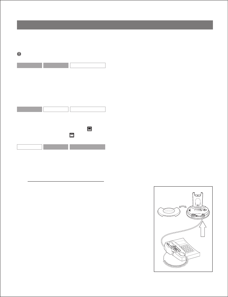
Setting up
You can set up your headset in 2 ways:
use with either telephone or PC or use
with both telephone and PC.
Connecting to telephone
[3.1] Unplug handset cord.
[3.2] Plug handset cord to base.
[3.3] Plug base’s cord to telephone.
Connecting to PC via USB
Note: Unit ID will appear as GN 9350.
[3.4] Plug small end of supplied USB
cord to base’s USB port.
[3.5] Plug large end of supplied USB cord
to PC’s USB port.
4
Your PC’s standard drivers will be used.
See Guide for additional functions for
supported operating systems.
Connecting to power
[3.6] Plug power adapter into base.
[3.7] Plug power adapter into electrical
outlet.
4
Telephone mode button will light.
Page 6
Page 7
1 sec )))
25 %
100 %
A
B
C
D
E
F
G
4.1-4.2 4.3
4.4 4.5 4.6-4.7
Charging/Dial tone Charge/Tonalité Carga/tono de llamada
4
|
See www.
gnnetcom.com/
gn9300/support
for more about
clear dial tone
adjustment.
|
Pour plus d’infos
sur le réglage de
la tonalité,
consultez www.
gnnetcom.
com/gn9300/
support.
|
Visite www.
gnnetcom.com/
gn9300/support
para obtener
más información
acerca del ajuste
de tono de
llamada claro.
|
See Guide for
additional func-
tions for
instructions on
changing the
battery.
|
Pour changer
la batterie,
voir Guide des
fonctions addi-
tionnelles.
|
Consulte la Guía
de funciones
adicionales para
obtener instruc-
ciones acerca de
cómo cargar la
batería.
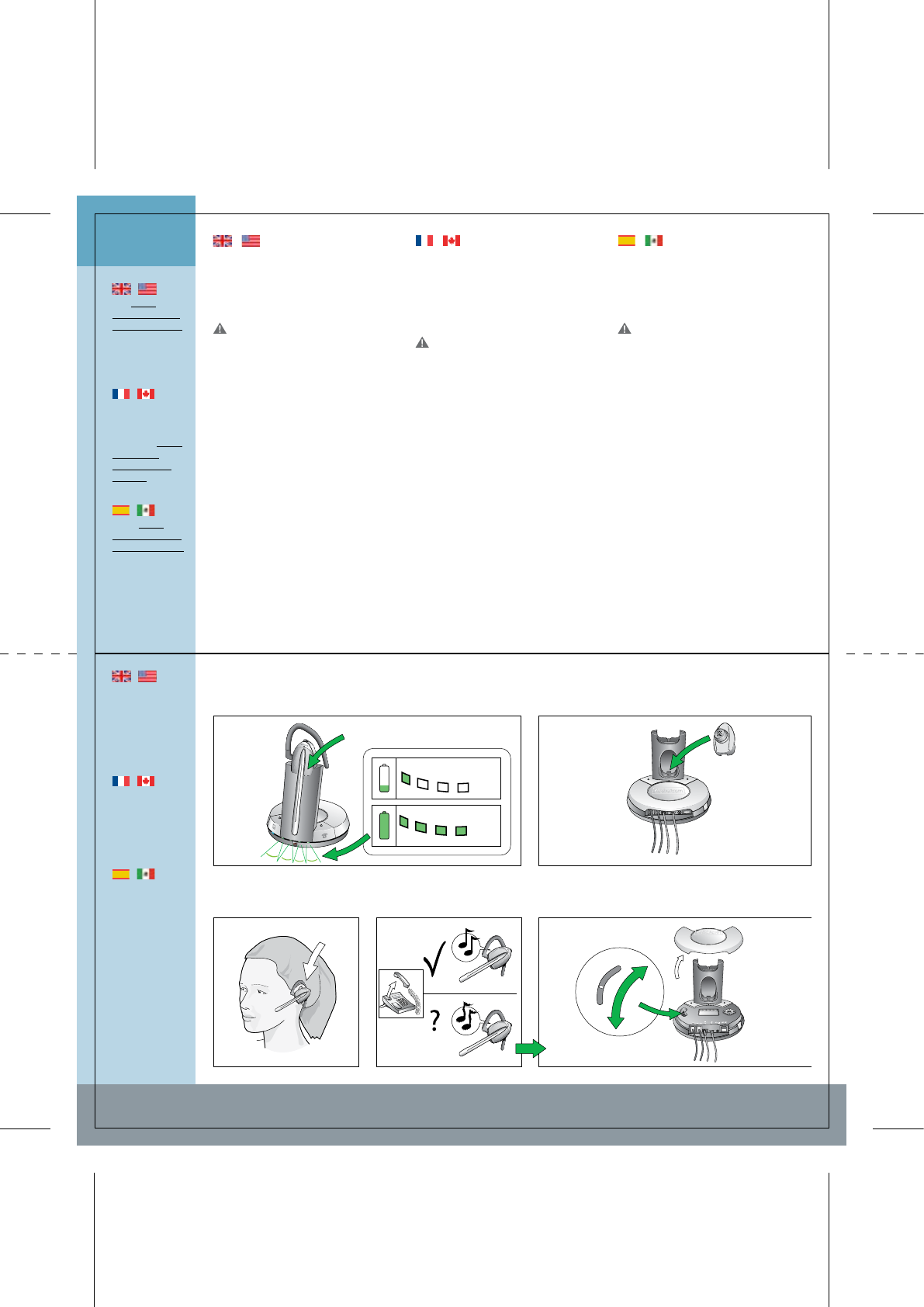
Charging
Charge
Carga
Clear dial tone adjustment
Réglage de la tonalité
Ajuste de tono de llamada
| English | Français | Español
Charge
[4.1] Placez le micro-casque dans le
berceau de charge.
4
Toutes les diodes du voyant de
batterie s’allument 1 seconde.
La perche micro doit être rétractée
pendant la charge.
[4.2] Chargez le micro-casque au
moins 30 mn (charge complète : 3 h).
4
Le nombre de diodes allumées indique
le niveau de charge, même si le micro-
casque n’est pas dans la base.
[4.3] La batterie supplémentaire peut
être chargée sur le socle de charge.
Réglage de la tonalité
[4.4] Mettez le micro-casque.
[4.5] Décrochez le combiné, vous
entendez la tonalité dans le casque.
4 En l’absence de tonalité ou si elle n’est
pas nette, poursuivez le réglage, voir 4.6.
[4.6] Retirez le couvercle pour accéder
à la molette de réglage de la tonalité.
[4.7] Faites-la coulisser de A à G pour
obtenir une tonalité nette. Si celle-ci est
aussi nette sur A que sur G, restez sur A.
Charging
[4.1] Put headset in base to charge.
4 All Battery indicator diodes will
light for 1 sec.
The boom arm must be in retracted
position for charging.
[4.2] Charge headset for minimum 30
min. before use. A full charge takes 3 h.
4 The number of lit battery indicator
diodes show level of charge, even with
headset out of base.
[4.3] The extra battery can be charged
in its receptor (on charge tower).
Clear dial tone adjustment
[4.4] Put on headset.
[4.5] Lift handset and listen for dial
tone in headset.
4 If no/unclear dial tone is heard,
continue adjustment to 4.6.
[4.6] Remove base cover and locate
clear dial tone switch.
[4.7] Slide the switch (through A-G
settings) until dial tone is clear. If dial
tone is just as clear in position A as in
position G, leave switch in position A.
Carga
[4.1] Ponga microcasco en la base.
4 Todos los diodos del indicador de
batería se iluminarán un segundo.
Para realizar la carga, la varilla debe
estar en posición retráctil!.
[4.2] Antes de usar microc., cargar
mín. 30 min. Carga completa: 3 h.
4 El nº de diodos iluminados indica
nivel de carga de batería, incluso con
microc. fuera de base.
[4.3] La batería adicional puede cargarse
en su receptor (en la torre de carga).
Ajuste de tono de llamada
[4.4] Póngase el microcasco.
[4.5] Levante el microteléfono y espe-
re a oír el tono de llamada.
4 Si no se oye tono o éste no es claro,
realice el paso siguiente.
[4.6] Retire la tapa de la base y localice
el conmutador de tono de llamada claro.
[4.7] Desplace el conmutador (por A-
G). Si el tono es igual de claro en A que
en G, déjelo en A.
Page 8
Page 9
5.1 5.2 5.3
5.5 5.75.6
5.4
Volume Volume Volumen
5
|
For a USB
application, the
computer’s
settings deter-
mine transmit
volume.
|
Avec une
application USB,
le volume de
transmission
se règle sur
l’ordinateur.
|
Si utiliza una
aplicación USB,
la configuración
del equipo
determinará
el volumen de
transmisión.
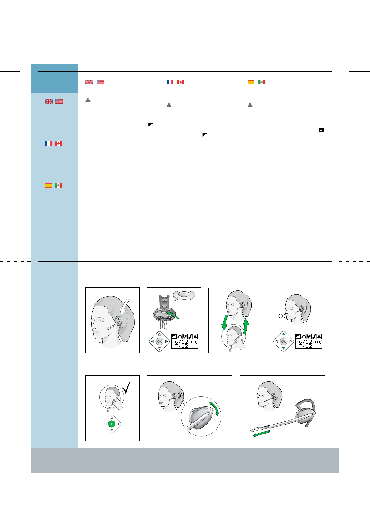
Transmit volume setting
Réglage du volume de transmission
Ajuste del volumen de transmisión
Adjusting speaker volume
Réglage du volume de réception
Ajuste de vol. de recepción
Extendable boom arm
Perche micro extensible
Varilla extensible
| English | Français | Español
Page 10
Page 11
Réglage du volume de
transmission
Ce réglage est indispensable pour
que votre voix soit clairement audible.
[5.1] Mettez le micro-casque.
[5.2] Sur le menu de l’afficheur de la
base, recherchez réglage du volume
de transmission .
[5.3] Appelez la personne qui doit
vous aider pour l’essai.
[5.4] Faites défiler le menu réglage
du volume de transmission (12
réglages) jusqu’à ce que la personne
confirme que le volume de votre voix
est correct.
[5.5] Appuyez sur OK pour confirmer
le nouveau réglage.
Réglage du volume de réception
[5.6] Pour régler le volume, déplacez
la commande vers le haut/bas.
4 Le casque émet des bips indiquant le
volume sonore.
Perche micro extensible
[5.7] En environnement bruyant, vous
pouvez allonger la perche micro. Pour
cela, tirez doucement jusqu’à ce qu’elle
se bloque. Pour rétracter la perche,
enfoncez-la doucement.
Ajuste del volumen de
transmisión
Este ajuste es muy importante para
que su voz se oiga claramente!.
[5.1] Póngase el microcasco.
[5.2] En el menú de la base, localice el
ajuste de volumen de transmisión .
[5.3] Realice una llamada de prueba a
alguien.
[5.4] Desplácese por las 12 opciones
del menú de ajuste del volumen de
transmisión hasta que se le confirme
un volumen de voz adecuado.
[5.5] Pulse OK (Aceptar) para confir-
mar la nueva configuración.
Ajuste de vol. de recepción
[5.6] Mueva el conmutador de vo-
lumen arriba y abajo para ajustar el
volumen de recepción.
4 Los tonos del microcasco indican el
nivel del volumen.
Varilla extensible
[5.7] La varilla del microcasco es
extensible y puede alargarse si el am-
biente es ruidoso. Para ello, tire de la
varilla suavemente hasta el tope. Para
devolver la varilla a la posición retráctil,
empújela suavemente.
Transmit volume setting
This setting is critical for your voice
to be heard clearly.
[5.1] Put on headset.
[5.2] From base’s display menu, locate
transmit volume adjustment .
[5.3] Make a call to someone who will
act as test person.
[5.4] Scroll through 12-setting trans-
mit volume adjustment menu until
your test person confirms your voice is
at appropriate volume.
[5.5] Press OK to confirm new setting.
Adjusting speaker volume
[5.6] Push volume switch up/down to
adjust receive volume.
4 Tones in headset indicate volume
level.
Extendable boom arm
[5.7] The headset’s boom arm is
extendable and may be extended if in
a noisy environment. Extend the boom
arm by gently pulling it until it stops.
Retract the boom arm by gently push-
ing it back.
6.7 6.8 6.9 6.10 6.11
6.1 6.2 6.3 6.4 6.5 6.6
Calling Téléphoner Realizar llamadas
6
|
USB/Telephone
mode button in-
dicators: Lit when
base is in selec-
ted mode (USB or
telephone) and
flashing when link
in the selected
mode is active.
|
Voyants des
touches USB/-
Téléphone :
allumés quand la
base se trouve
dans le mode
sélectionné (USB
ou Téléphone) et
clignotants quand
la liaison est
établie dans le
mode sélectionné
|
Indicadores del
botón de modo
USB/teléfono: se
iluminan cuando
la base está en
modo selec-
cionado (USB
o teléfono) y
parpadea cuando
la conexión en el
modo seleccio-
nado está activa.
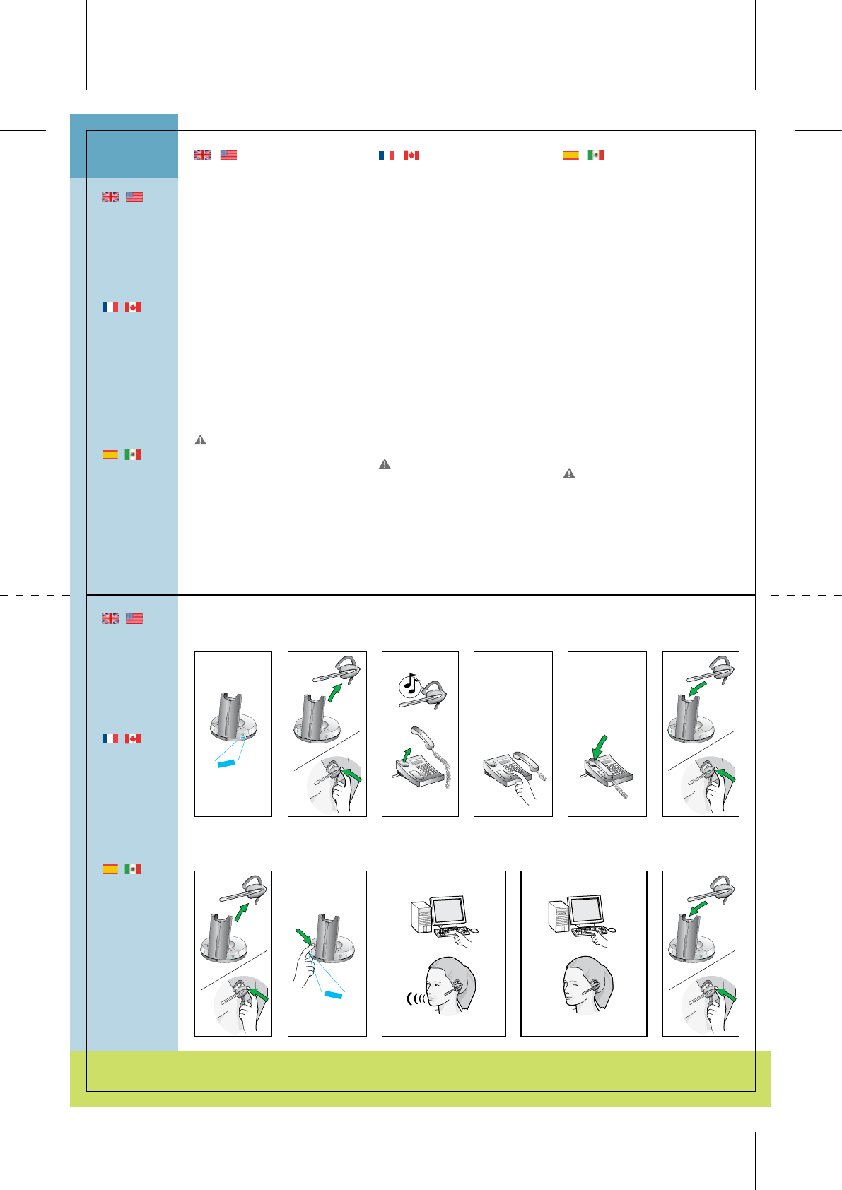
Making calls via telephone
[6.1] Ensure telephone mode is
selected.
[6.2] Remove headset from base, or
press headset’s talk button if already
wearing headset.
[6.3] Lift telephone’s handset and
wait for dial tone.
[6.4] Dial desired number.
Ending calls
[6.5] Place telephone’s handset.
[6.6] Place headset in base, or press
headset’s talk button.
Making calls via
PC/VoIP application
[6.7] Remove headset from base, or
press headset’s talk button if already
wearing headset.
[6.8] Ensure USB mode is selected.
USB button’s indikator will light.
[6.9] Complete call according to your
PC application’s instructions.
Ending calls
[6.10] End call according to your
PC application’s instructions.
[6.11] Place headset in base, or press
headset’s talk button.
|
To make/end
calls remotely
via telephone
using remote
handset lifting
functionality.
See Guide for
additional
functions for
instructions.
|
Pour appe-
ler/raccrocher
à distance via
le téléphone à
l’aide de la fonc-
tion de décroché
à distance, voir
instructions
du Guide des
fonctions addi-
tionnelles.
|
También puede
realizar y finali-
zar llamadas de
forma remota
a través de la
funcionalidad
de descolgador
remoto de mi-
croteléfono.
Consulte la Guía
de funciones
adicionales para
obtener instruc-
ciones.
Making calls via telephone
Passer un appel via le téléphone
Llamadas a través del teléfono
Making calls via PC/VoIP application
Passer un appel via un ordinateur (VoIP)
Realización de llamadas a través de una aplicación VoIP o el PC
| English | Français | Español
Passer un appel via le téléphone
[6.1] Vérifiez que le mode Téléphone
est sélectionné.
[6.2] Retirez le micro-casque de la
base ou, si vous le portez déjà, ap-
puyez sur sa touche Conversation.
[6.3] Décrochez le combiné et atten-
dez la tonalité.
[6.4] Composez le numéro.
Terminer un appel
[6.5] Raccrochez le combiné téléphonique.
[6.6] Replacez le micro-casque dans
la base, ou appuyez sur le bouton de
conversation du micro-casque.
Passer un appel via un
ordinateur (VoIP)
[6.7] Prenez le micro-casque dans la
base ou, si vous le portez déjà, ap-
puyez sur sa touche Conversation.
[6.8] Vérifiez que le mode USB est
sélectionné.
Le voyant de la touche USB s’allume.
[6.9] Passez l’appel selon les instruc-
tions de votre logiciel.
Terminer un appel
[6.10] Terminez l’appel selon les
instructions de votre logiciel.
[6.11] Replacez le micro-casque dans
la base, ou appuyez sur le bouton de
conversation du micro-casque.
Llamadas a través del teléfono
[6.1] Asegúrese de haber seleccionado el
modo de teléfono.
[6.2] Retire el microcasco de la base, o
bien pulse el botón de conversación
si ya lleva el microcasco.
[6.3] Levante el microt. y espere a oír
el tono de llamada.
[6.4] Marque el número deseado.
Finalización de llamadas
[6.5] Vuelva a colocar el microteléfono
en su sitio.
[6.6] Coloque el microcasco en la base,
o pulse el botón de conversación del
microcasco.
Realización de llamadas a
través de una aplicación VoIP
o el PC
[6.7] Retire el microcasco de la base, o
bien pulse el botón de conversación
si ya lleva el microcasco.
[6.8] Asegúrese de seleccionar el modo USB.
Se iluminará el indicador del botón de USB.
[6.9] Finalice la llamada siguiendo las
instrucciones de la aplicación de PC.
Finalización de llamadas
[6.10] Finalice la llamada siguiendo las
instrucciones de la aplicación de PC.
[6.11] Coloque el microcasco en la base,
o pulse el botón de conversación del
microcasco.
Page 12
Page 13
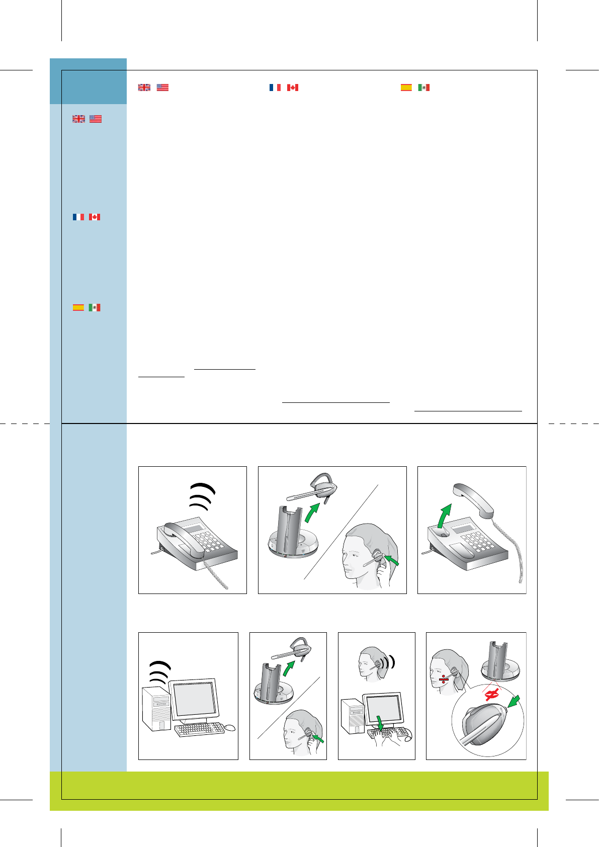
Answering calls via telephone
Répondre à un appel via le téléphone
Cómo responder llamadas a través del teléfono
Answering calls via VoIP application manually
Répondre via une application VoIP manuellement
Cómo responder llamadas a través de una aplicación VoIP manualmente
7.2 7.37.1
Mute functionality
Fonction Secret
Funcionalidad de silencio
7.4 7.5 7.77.6
Answering calls Répondre à un appel Responder llamadas
7
|
When receiving
calls, the unit
automatically
selects the
required tele-
phone or VoIP
mode. When the
call is finished, it
reverts back to
the manually-
selected mode.
|
A l’arrivée d’un
appel, l’appareil
sélectionne au-
tomatiquement
le mode télé-
phone ou VoIP.
En fin d’appel, il
revient au mode
sélectionné
manuellement.
|
Al recibir
llamadas, la
unidad auto-
máticamente
selecciona el
modo requerido
de teléfono o
VoIP. Al finalizar
la llamada,
vuelve al modo
seleccionado
manualmente.
Répondre à un appel via le
téléphone
[7.1] Le téléphone sonne.
[7.2] Prenez le micro-casque dans la
base ou, si vous le portez déjà, ap-
puyez sur sa touche Conversation.
[7.3] Décrochez le combiné télépho-
nique.
4 L’appel est transféré au micro-cas-
que.
Répondre via une application
VoIP manuellement
[7.4] L’application VoIp de votre ordi-
nateur signale les appels entrants.
[7.5] Prenez le micro-casque dans la
base.
4 L’appel est transféré.
[7.6] Activez manuellement la fonction
de prise d’appel de l’application VoIP.
4 L’appel est transféré.
Fonction Secret
[7.7] Pour activer/désactiver la fonc-
tion Secret, appuyez sur le bouton de
réglage du volume.
4 En mode Secret, vous entendez des
bips réguliers dans le casque et le
voyant Secret de la base s’allume.
Note : Certaines applications VoIP permet-
tent de prendre les appels/raccrocher à dis-
tance et transmettent le signal de sonnerie.
Voir www.gnnetcom.com/gn9300/support
pour plus de détails.
Cómo responder llamadas a
través del teléfono
[7.1] El teléfono sonará.
[7.2] Retire el microcasco de la base, o
bien pulse el botón de conversación
si ya lleva el microcasco.
[7.3] Levante el microteléfono.
4 La llamada se dirigirá al microcasco.
Cómo responder llamadas a
través de una aplicación VoIP
manualmente
[7.4] La aplicación VoIP de su PC le
indicará cuando tiene una llamada
entrante.
[7.5] Retire el microcasco de la base.
4 Se realizará la conexión de llamada.
[7.6] Active manualmente la funcio-
nalidad para responder llamadas de la
aplicación VoIP del PC.
4 Se realizará la conexión de llamada.
Funcionalidad de silencio
[7.7] La funcionalidad de silencio
(“mute”) se activa/desactiva pulsando
el silenciador del control del volumen.
4 Cuando la funcionalidad de silencio
está activada, el microcasco emite un
tono a intervalos regulares y el indica-
dor de silencio de la base se ilumina.
Nota: Algunas aplicaciones VoIP permiten
responder y finalizar llamadas remotas y
transmitir la señal de llamada. Consulte el
sitio www.gnnetcom.com/gn9300/support
para obtener más detalles.
Answering calls via telephone
[7.1] The telephone will ring.
[7.2] Remove headset from base, or
press headset’s talk button if wearing
headset.
[7.3] Lift telephone’s handset.
4 The call will be directed to headset.
Answering calls via VoIP
application manually
[7.4] Your computer’s VoIP application
will notify you of an incoming call.
[7.5] Remove headset from base.
4 The call will be connected through.
[7.6] Manually activate your compu-
ter’s VoIP application’s call answer
functionality.
4 The call will be connected through.
Mute functionality
[7.7] Mute functionality is activated/
deactivated by pressing the volume
control’s mute switch.
4 When mute is activated, a tone in
regular intervals is heard in headset,
and mute indicator on base lights.
Note: Some VoIP applications allow remote
answering and ending of calls and transmit
the ring signal. See www.gnnetcom.com/
gn9300/support for more details.
| English | Français | Español
Page 14
Page 15

81-00110 �0 �
Guide for additional functions ENG 1
Anleitung für zusätzliche Funktionen DE 20
Guide des fonctions additionnelles FR 40
Guía de funciones adicionales ES 60


English – GN 9350/GN 9330/GN 9330 USB
Guide for additional functions
This Guide for additional functions supplements the GN 9350/GN 9330/GN 9330 US�
Guides for basic set-up and use. It provides instructions and information on the GN 9350’s/
GN 9330’s/GN 9330 US�’s additional functions, features, accessories and maintenance.
The Guides for basic set-up and use provide the basic instructions for setting up and using
your GN 9350/GN 9330/GN 9330 US�.
This Guide for additional functions contains information common to the GN 9350,
GN 9330 and GN 9330 US�. Each subchapter is clearly marked GN 9350 GN 9330
GN 9330 USB , to which products they concern. When the feature does not apply, it will
simply have a wire-frame box and no grey fill, i.e. GN 9350 GN 9330 GN 9330 USB
1. Product information ................................................... 3
2. Setting up ............................................................ 4
2.1 Headset port.......................................................................... 4
2.2 Default Outbound Call mode .......................................................... 4
2.3 Connecting to the GN 1000 RHL (Remote Handset Lifter) (GN Netcom accessory).... 4
2.4 Connecting to external OLI (GN Netcom accessory) ................................... 5
2.5 LCD display ........................................................................... 5
2.5.1 Transmit volume................................................................. 5
2.5.2 Hookswitch selection............................................................ 6
2.5.3 Range/power selection.......................................................... 6
2.5.4 Sound mode selection........................................................... 7
2.5.5 Protection level selection ........................................................ 8
3. Wearing styles ........................................................ 9
3.1 Headband wearing styles ............................................................. 9
3.2 Neckband wearing styles.............................................................. 9
3.3 Ear hook wearing styles............................................................... 10
3.4 Changing wearing styles .............................................................. 10
3.5 Receive volume button reorientation.................................................. 10
1

4. Operating the headset ................................................ 10
4.1 Making/ending calls via telephone with RHL function ................................. 10
4.2 Answering calls via telephone with RHL function...................................... 11
4.3 Conference calling..................................................................... 11
4.4 Emergency calling via VoIP ............................................................ 12
4.5 Switching a call from headset to desk telephone handset............................. 13
4.6 Switching a call from desk telephone handset to headset............................. 13
4.7 New master headset pairing to base . . . . . . . . . . . . . . . . . . . . . . . . . . . . . . . . . . . . . . . . . . . . . . . . . . 13
5. Use with DECT cordless telephones ..................................... 14
6. Replacing battery pack ................................................ 14
6.1 Extra battery pack ..................................................................... 14
6.2 Replacing battery pack ................................................................ 15
6.3 Adding extra battery charging facility (GN Netcom accessory)......................... 14
7. Audio and visual indicators ............................................ 15
7.1 Headset’s audio indicators ............................................................ 16
7.2 Headset’s visual indicators ............................................................ 16
7.3 �ase’s visual indicators................................................................ 17
8. Troubleshooting ...................................................... 17
9. Maintenance, safety and disposal ...................................... 18
2
1. Product information
The GN 9350/GN 9330/GN 9330 US� are fully wireless, robust headset solutions. They all
share hands-free working efficiency, wireless mobility, useful features, and many customizing
and accessory options.
�elow is an overview of the primary features and functions offered within each model
number:
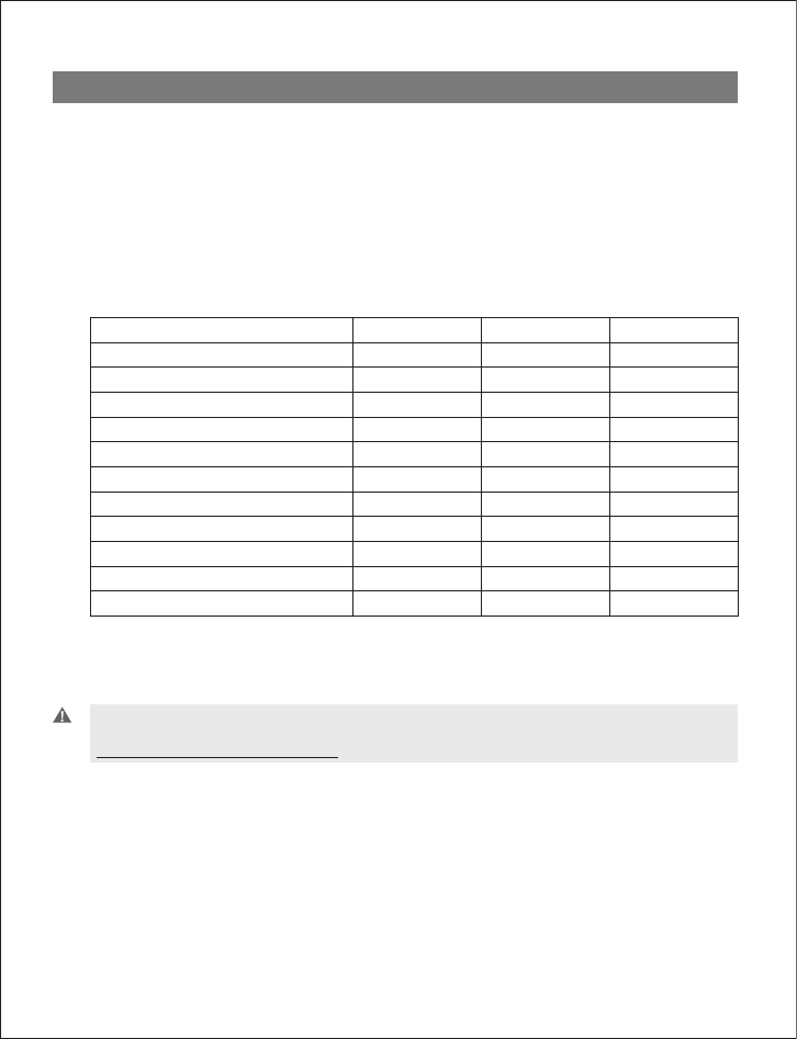
Comparison of features by model type
Features: GN 9350 GN 9330 GN 9330 USB
Desk telephone connectivity • •
VoIP/ US� connectivity ** • •
GN 1000 RHL enabled • •
Electronic hookswitch enabled •
Display for set-up •
Adjustable range •
Sound refinement (DSP) •
Extendable boom arm •
Conference call •
On-line indicator connectivity • • •
DECT/GAP enabled* •
* not applicable for US version
** for connecting to your PC, the headsets only work with the Windows 98 (SE), Windows 2000 and
Windows XP operating systems.
Important: When using your GN 9350 or GN 9330 US� with a VoIP application, consult the
application’s user manual for complete information and instructions, or visit our web site
www.gnnetcom.com/gn9300/support.
3
2. Setting up
This section contains set-up and connection instructions for your headset’s accessories and
optional functions.
Note: Your Guide for basic set-up and use contains the primary set-up and connection instructions.
GN 9350 GN 9330 GN 9330 USB
2.1 Headset port
If your telephone has a port for headset, it is recommended to leave the handset cord in the
telephone. Connect the telephone’s headset port to the telephone port on the base. This will
enable you to use the call button on your telephone, if there is one, and will limit the number
of wires coming out of your base.
GN 9350 GN 9330 GN 9330 USB
2.2 Default Outbound Call mode
The base is default set for telephone use. If you want to use your VoIP application as default
calling media, press the US� button for 5 seconds. If you want to change it back again,
press the Telephone button for 5 seconds
GN 9350 GN 9330 GN 9330 USB
2.3 Connecting to the GN 1000 RHL (Remote Handset Lifter)
(GN Netcom accessory)
You may purchase a GN 1000 RHL as an accessory, which lets you answer and end telephone
calls while away from your desk. Please contact your vendor or visit
www.gnnetcom.com/gn9300/support for further details.
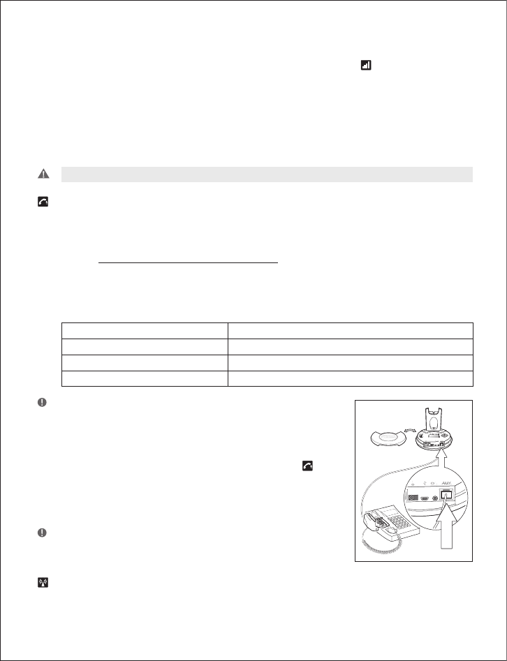
To connect your GN 1000:
1. Mount the GN 1000 to your telephone as described in
its user manual.
2. Plug RHL’s connection cord into headset base’s AUX port.
The GN 9350 enables you to use electronic hookswitch
(EHS) to answer and end calls while away from your desk.
Feature is described in section 2.5.2.
The remote answering and ending of calls is also available on
certain softphone/VoIP applications.
4
GN 9350 GN 9330 GN 9330 USB
2.4 Connecting to external Online Indicator (OLI) (GN Netcom accessory)
An external online indicator (accessory) can be placed on your desk or near your telephone to
indicate when you’re on a call.
To connect to an external OLI: Plug cord from OLI to base’s OLI port.
GN 9350 GN 9330 GN 9330 USB
2.5 LCD display
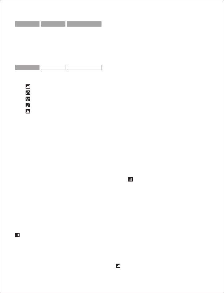
Your base unit has a LCD display and display control with which you control 5 settings:
Transmit volume setting
Hookswitch selection
Range/power selection
Sound mode selection
Protection level selection
Navigation and markers
Navigate through the LCD display’s 5 menus horizontally using the display control’s34
ar-
rows. Within each of the 5 menus, navigate vertically with the display control’s56arrows.
Press the OK button to confirm a specific choice/value within the 5 different menus. A star (*)
beside a selected choice/value indicates the current setting.
Default/start position
The LCD display is always on and ready to use. The permanent default/start position for the
LCD display is the leftmost transmit volume setting . The LCD display will always revert to
this default/start position, if not operated for 30 seconds.
Within each of the 5 menus, there is also a factory-set default. This default remains until you
change it. The last selected choice/value (within each of the 5 menus) is always displayed in
the first line of its menu.
Changing the settings
2.5.1 Transmit volume
The transmit volume must be adjusted properly so your voice is heard clearly.
If you haven’t already adjusted the transmit volume during your initial setting up, do so now
by completing the following:
1. Put on headset.
2. Use 34
to locate transmit volume menu on base display.
5
3. Make a call to someone who will act as a test person.
4. Use 56 to scroll through 12-setting transmit volume menu until your test person
confirms your voice is at the appropriate volume.
5. Press OK to confirm new setting.
The transmit volume menu is the permanent default/start position for the LCD display. After
adjusting any of the other settings via the display, it will revert to the transmit volume menu
position.
Important: For US� applications, the volume settings are fixed and need no adjustment.
2.5.2 Hookswitch selection
The GN 9350 enables you to answer and end calls remotely by using the GN 1000 RHL, or its
built-in electronic hookswitch (EHS) modes. EHS is only possible on certain telephone sys-
tems. In order to determine which telephones have the EHS feature enabled, please refer to our
website www.gnnetcom.com/gn9120/ehs-setup. Please also refer to your telephone´s user
manual for clarification.
4 modes are available
GN RHL non-EHS; works with the GN 1000 RHL
DHSG e.g. Siemens and Elmeg desk telephones
AEI e.g. with Tenovis desk telephones
MSH e.g. with Alcatel desk telephones
Note: �y default, the GN 9350 is set to the RHL interface, which also is
the correct setting if you manually operate your handset when answer-
ing/ending calls as described in the Quick set-up guide.
To select the appropriate interface:
1. Use 34
to locate the hookswitch selection menu
on base display.
2. Use 56 to select one of the 4 interfaces from the menu.
3. Press OK to confirm the interface.
Note: To use the DHSG, AEI or MSH function, connect the connec-
tion cord (accessory) to your desk telephone and the AUX port of
the GN 9350.
2.5.3 Range/power selection
Your headset offers 3 range/power modes (Normal, Low and Very Low). The Normal mode
6
is ideal for most users. However, if you experience interference from other communication
devices during your calls, you may want to switch to the Low or Very Low modes. Changing to
Low or Very Low modes will reduce the range of your headset.
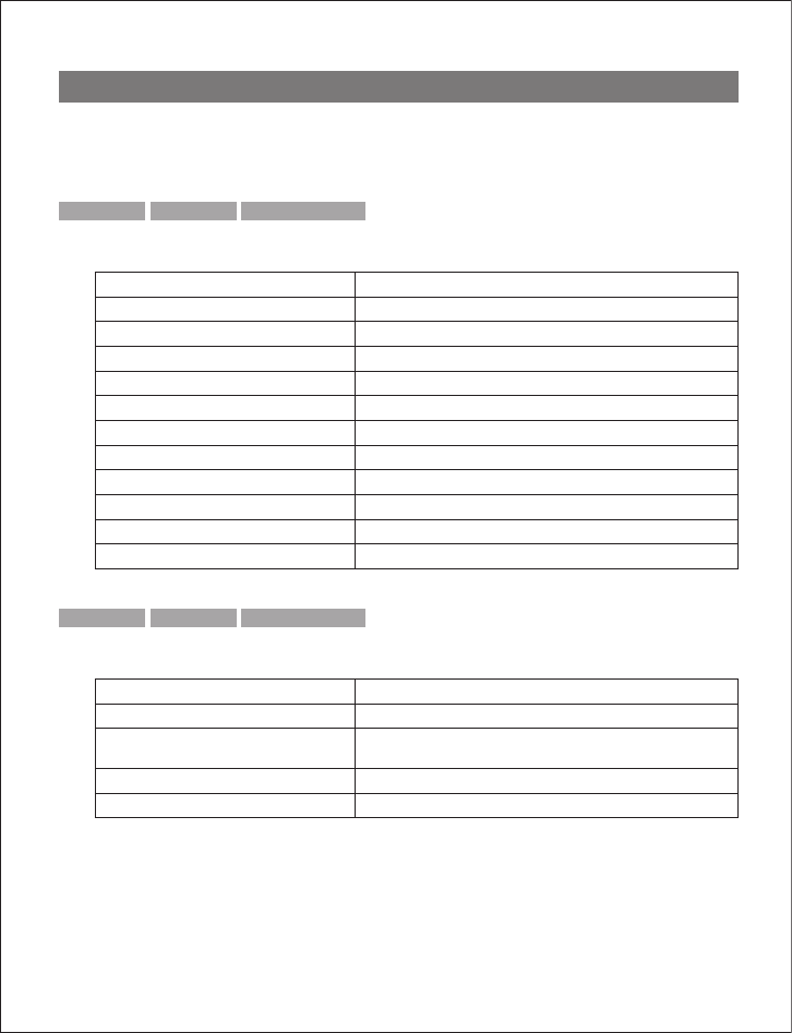
Power mode Range* Risk of interference
Normal Up to 150m/490 ft Average
Low Up to 30m/100 ft Low
Very Low (V. low) Approx. 10 m/33 ft Lowest
* In typical office environment
Note: The Normal power mode is the default setting.
To change the range/power mode:
1. Use 34
to locate the range/power mode menu on base display.
2. Use 56 to select one of the 3 modes from the menu.
3. Press OK to confirm the new mode.
2.5.4 Sound mode selection
This menu is split into two sections: “Treble/Normal/�ass” and “Fixed/Switch”. These two
sections are separated by a blank line. It is possible to choose one mode in each of the two
sections.
Your headset offers 3 treble/bass modes (Treble, Normal and �ass). You can change these to
suit your personal preferences or needs, and seperately determine the US� sound quality.
Sound mode Effect Benefits
Treble Accentuates high tones Ideal for users with slight high-
frequency hearing loss
Normal Accentuates all tones evenly Ideal for all users
�ass Accentuates lower tones Ideal for users preferring a bass-
rich sound
Note: The Normal mode is the default setting.
Sound mode Effect Benefits
Fixed Speech quality in headset loudspeaker as
known from traditional telephones
Improved talk time in US� mode
Switch Automatically switches to improved sound
quality. In conference call mode, automatic
switching is disabled.
Enhanced US� sound quality
7
Note: Switch is the default setting.
To change the sound mode:
1. Use 34
to locate the sound mode menu on base display.
2. Use 56 to select one of the 3 modes from the menu, and choose between
fixed/switched from the menu.
3. Press OK to confirm the setting.
2.5.5 Protection level selection
Your headset offers a choice of 4 protection levels (plus its additional basic protection level).
These levels protect you against sudden, overly-loud sound spikes that may come from the
phone network (such as shrill telefax signals or network interference), and provide a limit to
the maximum noise exposure from the headset during your workday.
The number of hours (on average) you spend on the telephone per day determines the set-
ting you should select. All 4 protection levels meet and exceed de facto global protection
levels, and are compliant with NIOSH standards, and EU health and safety codes of 85 d�(A).
The TT4 protection level is compliant with pertinent Australian legislation.
Important: In some jurisdictions, applicable regulations or laws may mandate the required setting
you use. The Default level provides a protection level of 118 d�(A). Your headset protects you
against overly-loud sound spikes. If you use the telephone’s handset for calling, you will not have
this protection.
Protection level Criteria for selecting
Level 0 �asic protection against overly-loud sound spikes
[118 db(A)]. Auto volume disabled
Level 1 Less than 4 hours on telephone/day
Level 2 4-8 hours on telephone/day
Level 3 More than 8 hours on telephone/day
Level 4 (TT4) Required Australian protection level
* Compliant with Directive 2003/10/EC of the European Parliament and Council of 6 February 2003.
To change the protection level:
1. Use 34
to locate the protection level menu on base display.
2. Use 56 to select one of the 5 modes from the menu.
3. Press OK to confirm the new mode.
8
Automatic volume adjustment and noise reduction
Your headset offers two built-in features which give you optimum sound levels and quality.
�oth features operate automatically, so you need not make any adjustments to the headset.
Automatic volume adjustment
The automatic volume adjustment feature automatically sets the volume levels of all calls,
so that each call is heard at the same, consistent volume you have set. Autovolume is not
enabled in protection level 0.
Noise reduction
The automatic noise reduction feature improves the sound quality of incoming calls by re-
moving impurities transmitted with the signal, such as background noise from your caller’s
environment.
3. Wearing styles
Your headset offers headband, neckband and ear hook wearing styles.
Note: GN 9330 and GN 9330 US� come with an ear hook and a headband. Neckband is available as
an accessory.
GN 9350 GN 9330 GN 9330 USB
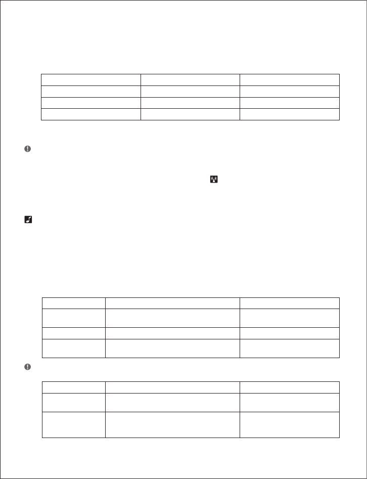
3.1 Headband wearing styles
You can choose to wear the headset on either the
left or right ear. The headset can be rotated 360˚.
Changing boom arm wearing side
(headband)
1. Rotate boom arm unit 90°.
GN 9350 GN 9330 GN 9330 USB
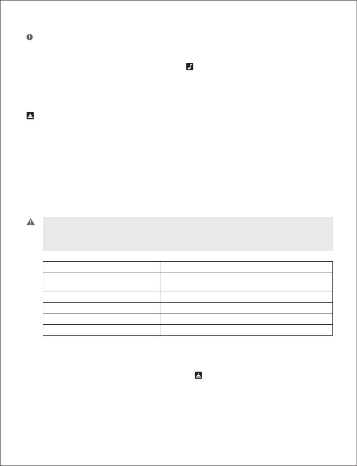
3.2 Neckband wearing style
With the neckband, the headset is worn on the right
ear.
Note: This wearing style is available as an accessory for
GN 9330 and GN 9330 US�.
9
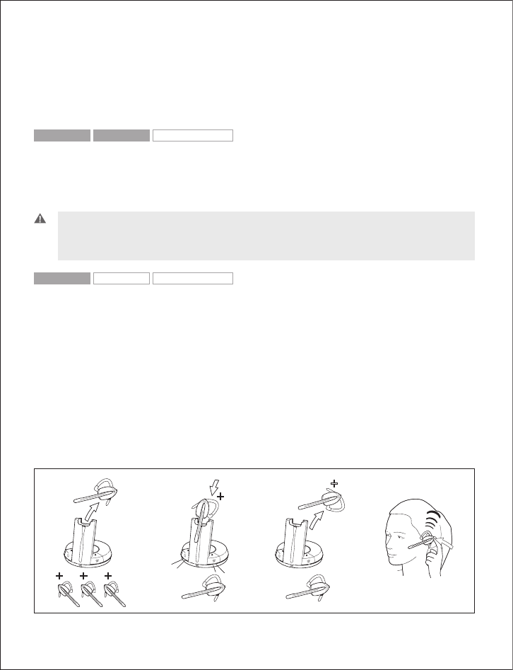
GN 9350 GN 9330 GN 9330 USB
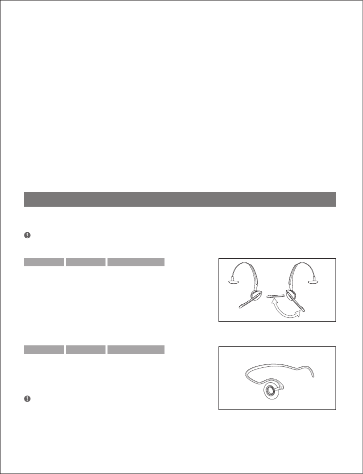
3.3 Ear hook wearing styles
You can choose to wear the headset on either the
left or right ear. The headset can be rotated 360˚.
Changing ear hook wearing side
1. Flip the ear hook over.
2. Rotate the ear hook 90°.
GN 9350 GN 9330 GN 9330 USB
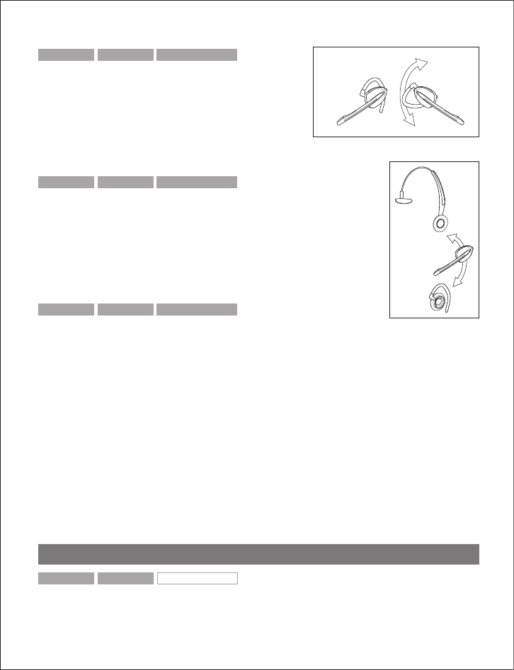
3.4 Changing wearing styles
All wearing styles (headband, neckband and ear hook) are inter-
changeable.
To change any wearing style (for example, from headband to ear hook):
1. Unclip headset from the current wearing style.
2. Affix the new wearing style.
GN 9350 GN 9330 GN 9330 USB
3.5 Receive volume button reorientation
�y default, the headset is set-up for wearing on the right ear. This means the volume con-
trol is pushed up to increase the volume, and pushed down to decrease the volume. If you
change the wearing ear of the headset, you may also want to change the orientation of the
volume control so that volume is still increased by pressing the volume control up.
To change the headset’s volume control button orientation:
1. Make sure there is no link between the headset and the base, (indicator on headset is not
flashing).
2. Press the headset’s mute button for 10 seconds.
–> The headset’s link indicator will light.
3. Determine how you prefer to increase volume (pushing the control either up or down).
4. Press the volume control either up or down (according to preference) until the headset’s
link indicator turns off.
4. Operating the headset
GN 9350 GN 9330 GN 9330 USB
4.1 Making/ending calls via telephone with RHL/EHS function
1. Ensure telephone mode is selected.
10
2. Remove headset from base, or press headset’s talk button if already wearing it.
–> RHL/EHS function will activate (handset lifts/telephone line connection opens).
3. Dial desired number.
4. Replace headset in base, or press the headset’s talk button.
–> RHL/EHS function will deactivate (handset lowers/telephone line connection closes).
GN 9350 GN 9330 GN 9330 USB
4.2 Answering calls via telephone with RHL/EHS function
1. The telephone rings.
2. Remove headset from base, or press the headset’s talk button.
–> The call will be connected (handset lifts/telephone line connection opens).
Important: During an incoming call, your headset will automatically change to the required mode,
depending on whether the call is coming via the desk phone (telephone) or via VoIP (US�). After
the call, it will revert to the default mode you selected earlier. The initial factory-set mode is the
telephone mode.
GN 9350 GN 9330 GN 9330 USB
4.3 Conference calling
Conference calling lets several headsets join together for a call. The primary headset (A) + 3
extra headsets (�) can join a conference call initiated by the primary headset. (See illustration.)
Making conference calls
1. Remove primary headset from base; make sure link is established. Indicators on base and
headset are flashing.
2. Place secondary headset in primary headset’s base and press pairing button on base.
–> Primary base’s telephone and US� mode indicators, and secondary headset’s link indi-
cator, will light for 2 seconds.
3. Remove secondary headset from primary headset’s base.
4. After a 4-pitch tone is heard in the primary headset, press its talk button.
(i[Y
8 8 8
8
8
7
7
7
7
11
Important: Steps 2 to 4 may be repeated twice for 2 more secondary headset participants.
5. Use the primary headset’s telephone/VoIP application to dial desired number and initiate
conference call.
At any point during a call in progress, you may add secondary headsets to form a conference call.
A maximum number of 4 headsets (1 master plus up to 3 secondary) may join a conference call.
Ending conference calls for all participants
1. Place primary headset in its base, or press its talk button.
–> The conference call is now terminated for all participants.
Note: If the conference call was made via VoIP, you may need to perform additional steps to end
your call. See your VoIP application’s user instructions.
Ending conference calls for a secondary headset only
1. Place secondary headset in its own base, or press its talk button.
–> This participant is now terminated from the conference call.
GN 9350 GN 9330 GN 9330 USB
4.4 Emergency calling via VoIP
Your headset supports quicker emergency calling via VoIP applications (softphone).
If the headset is connected to a PC and the PC is screensaver-locked, you can still use the
headset to dial emergency services.
To call emergency services via VoIP:
1. Put on headset.
2. If the PC is on (even if screensaver-locked), press the base unit’s telephone mode button
and US� mode button simultaneously for 5 seconds.
–> The base will automatically dial the emergency services number.
Note: This emergency services feature works only with certain VoIP applications.
Please refer to www.gnnetcom.com/gn9300/support for more information.
GN 9350 GN 9330 GN 9330 USB
4.5 Switching a call from headset to desk telephone handset
It’s possible to switch a call in progress from the headset to the telephone’s handset:
1. Lift the telephone’s handset to your ear.
2. Do one of the following:
• Place the headset into the charging cradle.
12
• Press the headset’s talk button.
• Press the base’s telephone mode button.
–> The headset’s link indicator will stop flashing to indicate that the headset-base link
has been closed.
Important: If using electronic hookswitch on your telephone, do not place the headset into
the charging cradle, press the headset´s talk button or press the base´s telephone mode button,
as this will disconnect the call.
If the headset runs out of battery power, the headset-base link will remain active for up to 2
minutes to allow for battery changing.
GN 9350 GN 9330 GN 9330 USB
4.6 Switching a call from desk telephone handset to headset
It’s possible to switch a call in progress from the telephone’s handset to the headset:
1. Remove the headset from base, or if already out, press
the headset’s talk button. This establishes a link.
–> The headset’s link indicator will start flashing and the
call will be switched to the headset.
Note: Do not place handset before the call is over, as this will end
the call.
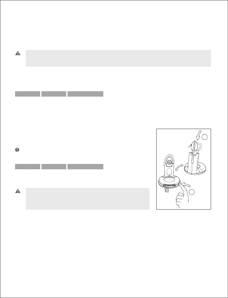
GN 9350 GN 9330 GN 9330 USB
4.7 New master headset pairing to base
You may designate a new master headset for your base.
Important: �efore designating a new master headset, ensure
that the original headset’s link to the base unit is closed by
pressing its talk button. The telephone or US� indicator should
not have a flashing light.
To designate a new master headset:
1. Place the new master headset into the charging cradle of the base.
2. Press the base’s pairing button.
–> �oth the telephone and US� mode buttons on the base, and the headset’s link indica-
tor, will light for 2 seconds. This indicates successful pairing of the new master headset.
'
(
13
5. Use with DECT cordless telephones
GN 9350 GN 9330 GN 9330 USB
Your headset can also be used with DECT cordless telephones (Digital Enhanced Cordless
Telecommunication), which are GAP-compatible (Generic Access Profile). You must first pair
the headset to the base unit of the cordless telephone.
Important: Your headset’s authentication code is 0000, which is the same code as for most DECT
cordless telephones. Your headset will only work with cordless telephones with the 0000 code.
To pair your headset to your DECT cordless telephone:
1. Press and hold down the headset’s talk button and mute button (at tip of volume control)
for 5 seconds.
–> The headset’s link indicator will flash rapidly.
2. Activate the cordless telephone’s GAP mode. Consult your cordless telephone’s manual
GAP compatibility/pairing instructions.
–> The headset’s link indicator will light for 2 seconds to indicate successful pairing.
Your headset is now ready to use with your cordless telephone. Consult your cordless
telephone’s user manual for using your headset with your cordless telephone.
6. Replacing the battery pack
GN 9350 GN 9330 GN 9330 USB
6.1 Extra battery pack
All 3 headset variants are equipped with a rechargeable, replace-
able battery pack designed to give you a long period of service. The
Guide for basic set-up and use covers instructions for charging your
headset.
For GN 9350, an extra battery is included with your headset, dou-
bling your talk time. The extra battery is charged by placing it into
its receptor at the back of the charge tower.
14
GN 9350 GN 9330 GN 9330 USB
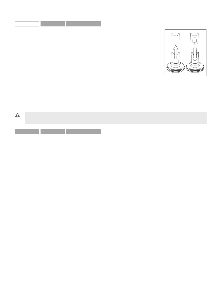
6.2 Adding extra battery charging facility
An extra battery charging facility is available as an accessory. This
can be attached to your base to allow you to charge an extra battery.
To add the extra battery charging facility cover:
1. Remove the blind cover from the base by sliding it upward until
removed.
2. Slide the extra battery charger into the base charge tower until it
clicks in place.
The extra battery can be charged in its receptor on the back of the charge tower. An LED
above the receptor will light when the battery is placed correctly and is charging. The LED will
turn off when battery is fully charged.
Important: During everyday use, the base’s leftmost to the left battery indicator will flash when
there is less than 30 minutes of talk time left.
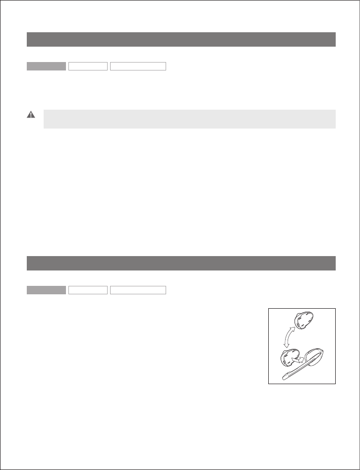
GN 9350 GN 9330 GN 9330 USB
6.3 Replacing the battery pack
The headset’s battery pack can be changed when required.
To replace the battery pack on a wearing style:
1. Unclip the wearing style from the battery pack.
2. Slide the battery pack off the headset.
3. Slide the new battery pack (from the extra battery charging facility) onto the headset.
The headset’s link indicator will light for 2 seconds to confirm successful replacement of
the battery pack.
4. Replace the wearing style.
5. Recharge the empty battery by sliding it into the extra battery charging facility.
15
7. Audio and visual indicators
The headset and base have audio and visual indicators that represent various functions as-
sociated with setting up and using the product.
GN 9350 GN 9330 GN 9330 USB
7.1 Headset’s audio indicator
Headset action Audio indication
Low battery 5 rapid beeps + 20 second pause
Volume up/down 1 quick beep in increasing/decreasing intensity
Volume max/min reached 1 rapid shrill/low beep
Incoming call (with RHL functionality) Rapid multi-tone + 2 second pause (repeats)
Incoming call (with VoIP call) Depends on VoIP application
Conference call request 4-pitch tone
Conference call accept 1 beep
Telephone line (open/close) 1 beep
Headset out of range 3-pitch tone
Mute activation/deactivation 1 beep
Mute activated 2-pitch tone + 10 second pause (repeats)
GN 9350 GN 9330 GN 9330 USB
7.2 Headset’s visual indicators
Visual indication Headset action
Link indicator (blue) Flashing when linked up
Lit for 2 seconds Successful pairing, including adding headsets in conference
mode
Lit (during adjustment) Receive volume reorientation (+/-) is being adjusted
Flashing rapidly Headset in DECT/GAP mode
16
GN 9350 GN 9330 GN 9330 USB
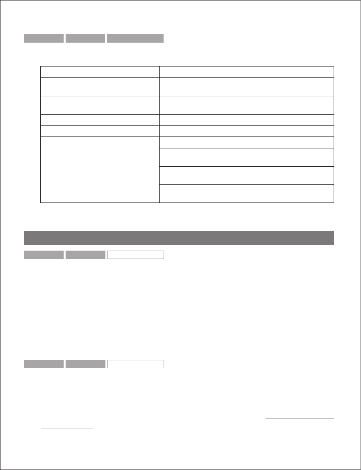
7.3 Base’s visual indicators
Base action Visual indication
Telephone mode button’s indicator/
�ase talk button
Lit when in telephone mode and flashing when linked up
US� mode button’s indicator/
�ase talk button
Lit when in US� mode and flashing when linked up
Mute functionality indicator (red) Lit when mute is activated
�attery indicator (4 green diodes) 1 LED light = 25% of a full charge
4 LED lights = 100% full charge
Rightmost lit diode flashes when charging, leftmost diodes
are lit
Leftmost diode flashes when <30 minutes of talk time
remaining
When headset placed in cradle for charging, all diodes light
for 1 second
8. Troubleshooting
GN 9350 GN 9330 GN 9330 USB
Q: Nothing happens when I try to adjust the clear dialtone.when I try to adjust the clear dialtone.
A: Make sure the base is set for telephone mode and the link is established (telephone but-
ton’s indicator on base is flashing). Also ensure that the telephone is activated (handset is off
the hook or line button is pressed).
Q: I am getting a buzzing sound on my headset.
A: If the unit has been correctly set-up, your telephone may not be fully immune to the radio
signals the headset uses. To overcome this problem, move the headset base at least 30 cm away
from the telephone. On GN 9350, you may want to reduce the range of your unit instead.
GN 9350 GN 9330 GN 9330 USB
Q: My customers say they cannot hear me.
A: Ensure the base unit is in the correct system setting by adjusting the clear dial tone switch.
You should experience a high quality dial tone from the headset. Then call a friend and adjust
your headset’s microphone as described in the Guide for basic set-up and use.
For setting information on your telephone system, please also refer to www.gnnetcom.com/
gn9300/support.
17

GN 9350 GN 9330 GN 9330 USB
Q: When I press the talk button, the GN 1000 RHL lifts, but the call is not
connected.
A: Make sure that you are using the telephone’s handset port, and not the headset port (if
your telephone has one), when using a GN 1000 RHL for remote answering.
Q: I have heard there is a GN Netcom wireless headset which has no need for
a GN 1000 RHL to answer calls remotely.
A: Yes, this is known as the EHS (electronic hookswitch) feature on the GN 9350, which some
telephone systems support. Check with your supplier for compatibility with your phone, and/
or consult our support site at www.gnnetcom.com/gn9120/ehs-setup.
Q: I have moved desks at work. Is it possible to put my headset onto another base?
A: Yes, this is possible. The headset only needs to be paired to the new base. Just follow the
procedure as described in section 4.7 of this guide.
Q: My telephone should be able to operate with the EHS version of
GN Netcom, but I cannot make it work.
A: Please refer to www.gnnetcom.com/gn9300/support for more information, including com-
patibility and the correct, clear dialtone switch setting.
9. Maintenance, safety and disposal
Maintenance
The headband, boom arm and ear hook can be wiped with a dry or slightly damp cloth. The
cords and base unit can be dry-dusted as required. The leatherette ear cushion(s) can be
cleaned or replaced. When cleaning, remove them and rinse with water. Leatherette ear
cushions and ear plates can be wiped with a damp cloth, with only a little dishwashing liq-
uid if required. Avoid getting moisture or liquids into any button sockets, receptors or other
openings. Avoid exposing the product to rain.
Children and product packaging
The packaging, including plastic bags and wrapping parts, are not toys for children. The bags
themselves or the many small parts they contain may cause choking if ingested.
Materials and allergies
The headband is made of stainless steel, which does not have a nickel-coated surface.
The stainless steel alloy has been tested for nickel release in accordance with the European
18

standard EN 1811:1998. According to EU Directive 94/27/EF, the nickel release must be below
0,50 μgram/cm2/week. The release from the headband was 0,02μgram/cm2/week.
The leatherette ear cushion(s) do not contain vinyl.
Batteries and product disposal
Do not expose batteries to heat or puncture them. Dispose of the product and/or batteries
according to local standards and regulations.
19
English 3
Français 7
Español 11
North American Declaration & Warranty
Déclarations et garantie pour les Etats-Unis, le Canada et l´Amérique Latine
GNWarrantyC_US_HIGH 5/4/05 4:18 PM Side 1

2
GNWarrantyC_US_HIGH 5/4/05 4:18 PM Side 2

3
English
USA Declaration
USA FCC part 15
For wireless products and telephones
FCC Notice to Users/Product Statements
This device complies with part 15 of the FCC rules. Operation is subject to
the following two conditions:
(1) This device may not cause harmful interference, and (2) This device
must accept any interference received, including interference that may
cause undesired operation.
Users are not permitted to make changes or modify the device in any way.
WARNING: Changes or modifications not expressly approved by
GN Netcom will void the user’s authority to operate the equipment.
Applies to wireless products only
Note: This equipment has been tested and found to comply with the lim-
its for a Class B digital device, pursuant to part 15 of the FCC Rules.
These limits are designed to provide reasonable protection against harm-
ful interference in a residential installation.
This equipment generates, uses and can radiate radio frequency energy
and, if not installed and used in accordance with the instructions, may
cause harmful interference to radio communications. However, there is
no guarantee that interference will not occur in a particular installation. If
this equipment does cause harmful interference to radio or television re-
ception, which can be determined by turning the equipment off and on,
the user is encouraged to try to correct the interference by one or more
of the following measures:
• Reorient or relocate the receiving antenna.
• Increase the separation between the equipment and receiver.
• Connect the equipment into an outlet on a circuit different from that to
which the receiver is connected.
• Consult the dealer or an experienced radio/TV technician for help.
Applies for wireless products with base station only
The user must place the base at least 8” (20cm) or more from any per-
sonnel and must not be co-loaded or operating in conjunction with any
other antenna or transmitter in order to comply with FCC RF exposure
requirements.
ACTA Required Customer Information
For Telephones
This equipment complies with Part 68 of the FCC Rules and the require-
ments adopted by ACTA. On the bottom of this equipment is a label that
contains, among other information, a product identifier in the format
US:1LSW4000BGN7170 (see list at the end of this statement). If re-
quested, this number must be provided to the telephone company.
This equipment connects to (USOC) RJ11C modular jacks for network
connection.
A plug and jack used to connect this equipment to the premises wiring
and telephone network must comply with the applicable FCC Part 68 rules
and requirements adopted by ACTA. A compliant telephone and plug is
provided with this product. It is designed to be connected to a compati-
ble modular jack that is also compliant.
The REN is used to determine the number of devices that may be con-
nected to a telephone line. Excessive RENs on a telephone line may
result in the devices not ringing in response to an incoming call. In most
but not all areas, the sum of the RENs should not exceed (5.0). To be
certain of the number of devices that may be connected to a line, as
determined by the total RENs, contact the local telephone company.
If your home has specialty wired alarm equipment connected to the tele-
phone line, ensure the installation of this device does not disable your
alarm equipment. If you have questions about what will disable alarm
equipment, consult your telephone company or a qualified installer.
If this equipment causes harm to the telephone network, the telephone
company will notify you in advance that temporary discontinuance of
service may be required. But if advance notice isn’t practical, the tele-
phone company will notify the customer as soon as possible. Also, you
will be advised of your right to file a complaint with the FCC if you believe
it is necessary.
The telephone company may make changes in its facilities, equipment,
operations or procedures that could affect the operation of the equip-
ment. If this happens the telephone company will provide advanced
GNWarrantyC_US_HIGH 5/4/05 4:18 PM Side 3

notice in order for you to make necessary modifications to maintain
uninterrupted service.
If this equipment is causing harm to the telephone network, the tele-
phone company may request that you disconnect the equipment until
the problem is solved.
Connection to party line service is subject to state tariffs. Contact the
state public utility commission, public service commission or corporation
commission for information.
NOTICE: If your home has specially wired alarm equipment connected to
the telephone line, ensure the installation of this [equipment] does not
disable your alarm equipment. If you have questions about what will
disable alarm equipment, consult your telephone company or a qualified
installer.
There are no repairs that the customer can perform. Defective units
must be returned to GN Netcom for repair.
Canada Declaration
IC Notice to Users/Product Statements
Operation is subject to the following two conditions:
(1) This device may not cause interference and (2) This device must
accept any interference, including interference that may cause undesired
operation of the device.
The term “IC:” before the certification/registration number only signifies
that registration was performed based on a Declaration of Conformity
indicating that Industry Canada technical specifications were met. It
does not imply that industry Canada approved the equipment.
Canada Terminal equipment
IC Notice to Users/Product Statements
NOTICE: This equipment meets the applicable Industry Canada Terminal
Equipment Technical Specifications. This is confirmed by the registration
number.
The Ringer Equivalence Number (REN) assigned to each terminal device
provides an indication of the maximum number of terminals allowed to
be connected to a telephone interface. The termination of an interface
may consist of any combination of devices subject only to the require-
ment that the sum of the ringe equivalence numbers of all the devices
does not exceed 5.
Repairs to certified equipment should be coordinated by a representative
designated by the supplier. Any repairs or alterations made by the user
to this equipment, or equipment malfunctions, may give the tele-
communications company cause to request the user to disconnect the
equipment.
Users should ensure for their own protection that the electrical ground
connections of the power utility, telephone lines and internal metallic
water pipe system, if present, are connected together. This precaution
may be particularly important in rural areas. Caution: Users should NOT
attempt to make such connections themselves, but should contact the
appropriate electric inspection authority, or electrician, as appropriate.
Description on safety in headsets
For your protection and comfort GN Netcom has implemented several pro-
tective measures in this headset as described above. These protections
were carefully designed to maintain safe volume levels and to ensure that
the headset operates in compliance with government safety standards.
To further ensure your safety, please abide by the guidelines listed below.
Warning!
Headsets are capable of delivering sounds at loud volumes and high-
pitched tones. Exposure to such sounds can result in permanent hearing
loss damage. Please read the safety guidelines below prior to using this
headset.
Safety guidelines
1. Prior to use of this product follow these steps:
• before putting on the headset, turn the volume control to its lowest
level,
• put the headset on, and then
• slowly adjust the volume control to a comfortable level and pitch.
4
GNWarrantyC_US_HIGH 5/4/05 4:18 PM Side 4

2. During use of this product
• avoid loud volume levels;
• if increased volume is necessary, adjust the volume control slowly; and
• if you experience discomfort in your ear or head, immediately remove
the headset and consult a physician.
Cautionary Notes to Computer Users:
When using any headset with a computer, care should be taken in dry or
low humidity environments to protect the user from electrostatic dis-
charge from the monitor (CRT). Computer monitors can induce a sub-
stantial electrostatic charge when turned on or off, or when there is a
power failure, and the resulting electrostatic discharge can be passed
through the headset to ground. A user in close proximity to or touching
the computer may feel a common “shock” sensation, similar to touching
a door knob after walking across a carpet, causing no harm to the user.
This discharge is entirely due to the computer monitor, the headset is
merely the shortest path to ground.
To minimize the possibility of electrostatic discharge through the
headset, you can:
• Use a grounded screen in front of the monitor.
• Use static dissipative wrist straps.
• Increase the relative humidity in the room to 60% or more.
• Install static dissipative carpets or floor covering.
• Remove the headset before turning the computer on or off.
GN Netcom products meet OSHA, FCC and CSA standards.
USA / Canada Warranty
Limited Warranty
GN Netcom warrants to the original consumer purchaser that, except for
the limitations and exclusions set forth below, the product shall be free
from defects in materials and workmanship for a period of one (1) year
from the date of original retail purchase (“Warranty Period”). The obliga-
tion of GN Netcom under this warranty shall be limited to repair or
replacement, at GN Netcom option, without charge, of any part or unit
that proves to be defective in material or workmanship during the
Warranty Period, provided the product is returned to GN Netcom at the
address listed under “How to Obtain Warranty Repairs.” Except as modi-
fied by applicable State Law, this warranty sets forth the extent and limit
of GN Netcom obligation to the purchaser and or user of the product.
Exclusions from Warranty
This warranty applies only to defective factory material and factory
workmanship. Any conditions caused by accident, abuse, misuse or
improper operation in violation of instructions furnished by GN Netcom
destruction or alteration, improper electrical voltages or currents, or re-
pair or maintenance attempted by anyone other than GN Netcom is not
a “defect” covered by this Warranty. In such cases, GN Netcom may
charge you for materials and labor, even during the Warranty Period. It is
the owner’s responsibility to operate and care for this product in
accordance with the operating instructions and specifications supplied
with the product; and repairs resulting from failure to do so are not
covered by the Warranty.
The warranty is void if the serial number, date code label, or product
label is removed.
The following parts are considered to be subject to wear and tear in
normal usage and are not covered by the Warranty: earhooks, decorative
finishes and all foam products (earpads, eargels, microphone covers.
Implied Warranty
Under state law, you may be entitled to the benefit of certain implied
warranties. These implied Warranties will continue in force only during
the Warranty Period. Some states do not allow limitations on how long
an implied warranty lasts, so the above limitation may not apply to you.
Incidental or Consequential Damages
Neither GN Netcom nor your retail dealer or selling distributor has any
responsibility for any incident or consequential damages including, with-
out limitation, commercial loss, or for any incidental expenses, loss of
time, or inconvenience. Some states do not allow the exclusion or limita-
tion of incidental or consequential damages, so the above limitation or
exclusion may not apply to you.
Other Legal Rights
This warranty gives you specific legal rights, and you may also have
other rights which vary from state to state.
5
English
GNWarrantyC_US_HIGH 5/4/05 4:18 PM Side 5

How to Obtain Warranty Repairs
For customer service and technical support, call GN Netcom at
1-800-826-4656 or 1-603-598-1100.
To obtain Warranty repairs, return your unit, shipping prepaid, direct to:
In USA:
GN Netcom
77 Northeastern Blvd.
Nashua, NH 03062 USA
In Canada:
GN Netcom
1515 Matheson Blvd., Unit 104
Mississauga, Ontario L4W 2P5
Please use the original container, if possible, or pack the unit in a sturdy
carton with sufficient packing material to prevent shipping damage.
Include the following information:
1. Your name, company name, address and telephone number.
2. A description of the problem.
3. A copy of your purchase receipt indiciating the model number and
date of purchase. Without proof-of-purchase, your warranty is defined
as beginning on the date of manufacture as labeled on the product.
For out-of-warranty products, also include:
1. A purchase order authorizing repair.
During the Warranty Period, shipping charges for return to you will be
paid by GN Netcom for a unit requiring any repair covered by the
Warranty. Return shipping will be charged to the customer during the
Warranty Period for a unit requiring no Warranty repair. These shipping
charges will be prepaid by GN Netcom and billed to the customer.
Damage occurring during shipment is deemed the responsibility of the
carrier, and any claim should be made directly to such carrier.
6
GNWarrantyC_US_HIGH 5/4/05 4:18 PM Side 6

Déclarations pour les États-Unis
États-Unis – FCC partie 15
Produits sans fil et téléphones
Notification de la FCC aux usagers/Déclarations relatives au produit
Ce dispositif est conforme à la partie 15 de la réglementation FCC. Son
utilisation est soumise aux deux conditions suivantes:
(1) Ce dispositif ne doit causer aucune interférence nuisible et (2) Ce
dispositif doit accepter toute interférence reçue, y compris celles suscep-
tibles d’avoir des effets indésirables sur son fonctionnement.
Les utilisateurs ne sont pas autorisés à modifier le dispositif de quelque
façon que ce soit. Tout changement ou modification non expressément
approuvé par GN Netcom annulera le droit de l’utilisateur à faire usage
de l’équipement.
ATTENTION: Changements ou modifications pas expressément approu-
vés par GN Netcom éliminera l'autorité de l'utilisateur a faire fonctionner
l'équipement.
Produits sans fil uniquement
Note: cet équipement a été testé et respecte les limites applicables aux
dispositifs numériques de Classe B, conformément à la partie 15 de la
réglementation FCC. Ces limites visent à garantir une protection
raisonnable contre les interférences nuisibles dans les installations rési-
dentielles.
Cet équipement génère, utilise et peut diffuser de l’énergie radioélec-
trique. S’il n’est pas installé et utilisé conformément à son mode d’em-
ploi, il peut causer des interférences nuisibles avec les radiocommunica-
tions. Toutefois, le constructeur ne peut garantir qu’aucune interférence
ne se produira dans une installation particulière. Si cet équipement
cause des interférences nuisibles avec la réception d’appareils de radio
ou de télévision, ce qui peut être déterminé en éteignant puis rallumant
les appareils, l’utilisateur peut tenter d’y remédier en prenant l’une ou
plusieurs des mesures ci-dessous:
• Réorienter ou déplacer l’antenne de réception.
• Mieux séparer l’équipement du récepteur.
• Raccorder l’équipement à une prise reliée à un circuit différent de celui
auquel est relié le récepteur.
• Demander de l’aide à son revendeur ou à un technicien de radio/télévi-
sion qualifié.
Produits sans fil avec base uniquement
Pour respecter les critères d'exposition aux radiofréquences de la FCC,
l'utilisateur doit placer la base à 20 cm au moins des personnes et ne
pas la charger ni l'utiliser avec un(e) quelconque autre transmetteur ou
antenne.
Information du client conformément aux exigences de l'ACTA
Téléphones
Cet équipement est conforme à la partie 68 de la réglementation FCC et
aux exigences de l'ACTA. Une étiquette comportant, entre autres, la
référence du produit dans le format US:1LSW4000BGN7170 (voir liste à
la fin de cette déclaration) est apposée sous le dispositif. Si nécessaire,
cette référence doit être transmise à l'opérateur téléphonique.
Cet équipement peut être raccordé aux prises modulaires (USOC) RJ11C
pour raccordement à un réseau.
Les fiches et prises utilisées pour raccorder cet équipement au réseau
électrique et téléphonique des locaux doivent être conformes à la partie
68 de la réglementation FCC et aux exigences de l'ACTA. Un téléphone et
une fiche conformes sont fournis avec le produit. Ceux-ci sont conçus
pour être raccordés à une prise modulaire compatible et conforme.
Le nombre équivalent de sonneries (REN) permet de déterminer le
nombre de dispositifs pouvant être reliés à une ligne téléphonique. Si le
REN est trop élevé pour la ligne téléphonique concernée, les appareils
pourront ne pas sonner lors des appels entrants. Dans la plupart des
zones, la somme des REN ne doit pas excéder 5. Pour vous assurer que
le nombre de dispositifs pouvant être reliés à la ligne, que vous avez ob-
tenu en faisant la somme des REN, est correct, veuillez contacter votre
opérateur téléphonique local.
Si votre habitation est équipée d'un système d'alarme relié à la ligne té-
léphonique, assurez-vous que l'installation de ce dispositif ne désactive
pas votre alarme. Pour toute question concernant les matériels
susceptibles de désactiver votre système d'alarme, veuillez consulter
votre opérateur téléphonique ou un installateur agréé.
7
Français
GNWarrantyC_US_HIGH 5/4/05 4:18 PM Side 7

Si cet équipement endommage le réseau téléphonique, l'opérateur télépho-
nique vous avertira à l'avance d'une éventuelle interruption temporaire du
service. Si cela n'est pas possible en pratique, l'opérateur téléphonique
vous avertira dès que possible. Vous serez aussi informé de votre droit à
déposer une réclamation auprès de la FCC si vous le jugez nécessaire.
L'opérateur téléphonique peut apporter à ses installations, équipements,
opérations ou procédures des modifications susceptibles d'affecter le
fonctionnement de cet équipement. Dans ce cas, il vous préviendra à
l'avance afin que vous puissiez prendre les mesures nécessaires pour
assurer la continuité du service.
Si cet équipement endommage le réseau téléphonique, l'opérateur télé-
phonique pourra vous demander de le déconnecter jusqu'à ce que le
problème soit résolu.
Connection à la ligne de service est sujet aux des tarifs d'état. Contac-
tez la commission d 'équipement collectif public, la commission de ser-
vice public ou la commission de société pour plus d'informations .
AVIS: Si votre maison a une alarme lié specifiquement à la ligne téléphoni-
que, assurez que l'installation de cet équipement ne pas neutraliser
votre équipement d'alarme. Si vous avez des questions a ce sujet,
veuiller consultez votre compagnie de téléphone ou un installeur qualifié.
Aucune réparation ne peut être effectuée par le client. Les appareils
défectueux doivent être renvoyés à GN Netcom pour réparation.
Déclarations pour le Canada
Notification d’IC aux usagers/Déclarations relatives au produit
L’utilisation est soumise aux deux conditions suivantes:
(1) Ce dispositif ne doit causer aucune interférence et (2) Ce dispositif
doit accepter toutes les interférences, y compris celles susceptibles
d’avoir des effets indésirables sur son fonctionnement.
La mention “IC:” placée avant le numéro de certification/agrément signi-
fie uniquement que l’agrément a été accordé sur la base d’une déclara-
tion de conformité indiquant que les spécifications techniques d’Industry
Canada sont satisfaites. Elle ne signifie pas qu’Industry Canada a homo-
logué l’équipement.
Équipements terminaux au Canada
Notification d’IC aux usagers/Déclarations relatives au produit
NOTIFICATION: cet équipement est conforme aux spécifications
techniques d’Industry Canada relatives aux équipements terminaux. Le
numéro d’agrément atteste de cette conformité.
Le nombre équivalent de sonneries (REN) attribué à chaque équipement
terminal permet de connaître le nombre maximum de terminaux pouvant
être connectés à une interface téléphonique. Une interface peut se
terminer par une combinaison quelconque de dispositifs à condition que
la somme du nombre équivalent de sonneries de tous les dispositifs
n'excède pas cinq.
La réparation des équipements homologués devra être coordonnée par
un représentant désigné par le fournisseur. Toute réparation ou dégrada-
tion de l'équipement par l'utilisateur, ou tout dysfonctionnement de
l'équipement, pourront justifier une demande de déconnexion de l'équi-
pement par l'opérateur de télécommunication.
Pour sa propre sécurité, l'utilisateur doit s'assurer que les systèmes de
mise à la terre de l'installation électrique, des lignes téléphoniques et du
réseau de canalisations interne du bâtiment, le cas échéant, sont raccor-
dés les uns aux autres. Cette précaution peut se révéler particulièrement
importante dans les zones rurales. Attention: l'utilisateur NE DOIT PAS
tenter d'effectuer lui-même de tels raccordements. Il doit contacter les
services de contrôle électrique compétents ou un électricien, selon le cas.
Sécurité des micro-casques
Pour votre protection et votre confort, GN Netcom a intégré à ce micro-
casque plusieurs systèmes de protection, comme indiqué précédemment.
Conçus avec soin, ces systèmes de protection permettent de maintenir
un niveau sonore parfaitement sûr et de garantir que le microcasque
fonctionne conformément aux normes de sécurité gouvernementales.
Pour renforcer encore votre sécurité, veuillez respecter les recommanda-
tions ci-dessous.
Attention !
Les micro-casques peuvent produire des volumes sonores élevés et des
8
GNWarrantyC_US_HIGH 5/4/05 4:18 PM Side 8
sons aigus. L'exposition à ce type de sons peut provoquer des pertes/-
lésions auditives définitives. Lisez attentivement les directives de sécu-
rité ci-dessous avant d'utiliser ce micro-casque.
Directives de sécurité
1. Avant d'utiliser ce produit, effectuez les opérations suivantes :
• avant de mettre le micro-casque, placez la commande de volume sur
son niveau le plus bas,
• mettez le micro-casque, puis
• réglez progressiv ement le volume sonore sur un niveau et une hauteur
confortables.
2. Pendant l'utilisation de ce produit
• évitez les niveaux sonores élevés ;
• si vous avez besoin d'augmenter le volume, réglez-le lentement avec la
commande ; et
• si vous ressentez une sensation d'inconfort au niveau des oreilles ou
de la tête, retirez immédiatement le micro-casque et consultez un
médecin.
Note de mise en garde aux utilisateurs d'ordinateurs
En cas d'utilisation d'un micro-casque avec un ordinateur dans un envi-
ronnement sec ou faiblement humide, il est important de protéger l'utili-
sateur contre les décharges électrostatiques provenant de l'écran (CRT).
En effet, les écrans d'ordinateur peuvent produire une charge électrosta-
tique importante lors de leur mise sous/hors tension ou en cas de cou-
pure de courant et la décharge électrostatique qui en résulte peut être
transmise à la terre par l'intermédiaire du micro-casque. Un utilisateur
situé dans le voisinage immédiat ou au contact de l'ordinateur pourra
éprouver une sensation de “choc” semblable à celle ressentie en tou-
chant une poignée de porte métallique après avoir marché sur une mo-
quette. Toutefois, ce phénomène n'est pas dangereux pour l'utilisateur.
Cette décharge est entièrement due à l'écran de l'ordinateur. Le micro-
casque constitue simplement le chemin le plus rapide vers la terre.
Pour minimiser les risques de transmission des décharges électrostatiques
par le micro-casque, vous pouvez:
• Installer un blindage mis à la terre devant l'écran de l'ordinateur.
• Utiliser des bracelets antistatiques.
• Maintenir dans la pièce une humidité relative supérieure ou égale à 60%.
• Installer des tapis/moquettes ou revêtements de sol antistatiques.
• Retirer le micro-casque avant d'allumer/éteindre l'ordinateur.
Les produits GN Netcom sont conformes à l'ensemble des normes OSHA,
FCC et CSA.
Garantie pour les États-Unis/le Canada
Garantie limitée
GN Netcom garantit à l'acheteur-utilisateur initial que, à l'exception des
restrictions et des exclusions exposées ci-dessous, le produit est exempt
de défauts de matériaux et de fabrication pour une période de un (1) an
à compter de la date d'achat chez un détaillant ("Période de garantie").
Les obligations de GN Netcom au titre de cette garantie sont limitées à
la réparation ou au remplacement, aux frais de GN Netcom et à son gré,
de toute pièce ou élément défectueux en termes de matériel ou de fabri-
cation pendant la période de garantie, sous réserve que le produit soit
retourné à GN Netcom, à l'adresse indiquée dans la rubrique "Comment
faire réparer votre appareil sous garantie". Sauf disposition contraire des
lois en vigueur dans l'État concerné, cette garantie précise l'étendue et
les restrictions des obligations de GN Netcom envers l'acheteur et/ou
l'utilisateur du produit.
Exclusions de garantie
Cette garantie s'applique uniquement en cas de défaut matériel ou de
fabrication. Ne constitue pas un "défaut" couvert par cette garantie
toute dégradation résultant d'un accident, d'un usage anormal, incorrect
ou impropre non conforme aux instructions de GN Netcom, d'une des-
truction ou d'une altération, de tensions ou de courants électriques in-
adaptés, ou de tentatives de réparation ou de maintenance par toute
personne n'appartenant pas à GN Netcom. Dans ce cas, GN Netcom est
en droit de vous faire payer les matériaux et la main-d'œuvre, y compris
en période de garantie. Il est de la responsabilité du propriétaire d'utili-
ser et d'entretenir ce produit conformément à la notice d'utilisation et
aux spécifications qui l'accompagnent. Les réparations résultant du
non-respect de ces obligations ne seront pas couvertes par la garantie.
La garantie sera annulée si le numéro de série, l'étiquette indiquant le
9
Français
GNWarrantyC_US_HIGH 5/4/05 4:18 PM Side 9

code date de fabrication ou l'étiquette du produit ne figurent pas sur le
dispositif.
Les composants suivants sont considérés comme sujets aux détériora-
tions et à l'usure induites par un usage normal et ne sont donc pas cou-
verts par la garantie: contours d'oreille, finitions décoratives et tous ac-
cessoires en mousse (oreillettes, protections du microphone, etc.).
Garantie implicite
Selon la loi en vigueur dans votre État, vous bénéficiez peut-être de cer-
taines garanties implicites. Ces garanties implicites ne seront applicables
que pendant la période de garantie. Certains États n'autorisent aucune
restriction de durée de la garantie implicite. Dans ce cas, vous n'êtes pas
concerné par la restriction mentionnée ci-dessus.
Dommages accessoires ou consécutifs
Ni GN Netcom ni votre détaillant ou fournisseur ne sont responsables
des éventuels dommages accessoires ou consécutifs, y compris mais de
façon non limitative les préjudices commerciaux, les frais accessoires, les
pertes de temps ou les préjudices secondaires. Certains États n'autori-
sent aucune exclusion ni restriction des dommages accessoires ou
consécutifs. Dans ce cas, vous n'êtes pas concerné par la restriction ou
exclusion ci-dessus.
Autres garanties juridiques
Cette garantie vous donne droit à des garanties juridiques spécifiques.
De plus, vous bénéficiez éventuellement d'autres garanties, variables
selon les États.
Comment faire réparer votre appareil sous garantie
Pour contacter le service client et l'assistance technique, appelez
GN Netcom au
1-800-826-4656 ou 1-603-598-1100.
Pour bénéficier de réparations sous garantie, veuillez envoyer votre
appareil en port payé directement à l'adresse suivante:
Aux États-Unis:
GN Netcom
77 Northeastern Blvd.
Nashua, NH 03062
États-Unis:
Au Canada:
GN Netcom
1515, Matheson est, pièce 104
Mississauga (Ontario) L4W 2P5
Canada
Utilisez l'emballage d'origine, si possible, ou emballez soigneusement
l'appareil dans un carton suffisamment solide pour éviter tout dommage.
Veuillez également fournir les éléments suivants:
1. Votre nom, nom de la société, adresse et numéro de téléphone.
2. Motif du retour.
3. Copie du justificatif d'achat indiquant le numéro de référence du
modèle et la date d'achat. En l'absence de justificatif d'achat, votre
garantie prendra effet à la date de fabrication indiquée sur l'étiquette
du produit.
Pour les produits hors garantie, veuillez également joindre:
1. Bon de commande autorisant la réparation.
Pendant la durée de la période de garantie, les frais de réexpédition de
l'appareil seront pris en charge par GN Netcom si les réparations sont
couvertes par la garantie. Toujours pendant la période de garantie, les
frais de réexpédition seront à la charge du client si l'appareil nécessite
des réparations non couvertes par la garantie. Ces frais d'expédition se-
ront prépayés par GN Netcom et facturés au client. Tout dommage causé
au cours du transport engage la responsabilité du transporteur et toute
plainte devra être adressée directement à ce transporteur.
Informations complémentaires et caractéristiques techniques:
www.gnnetcom.com
GN Netcom, Inc.
77 Northeastern Boulevard
Nashua, NH 03062
États-Unis
Tél. : 1-800-826-4656
Tél. : 1-603-598-1100
Fax : 1-603-598-1122
10
GNWarrantyC_US_HIGH 5/4/05 4:18 PM Side 10

Declaración para EE.UU.
FCC de EE.UU., parte 15
Para productos inalámbricos y teléfonos
Aviso de la FCC para declaraciones de usuarios/productos
Este dispositivo cumple con la parte 15 de las Normas de la FCC. El fun-
cionamiento está sujeto a las dos condiciones siguientes:
(1) Este dispositivo no puede causar interferencias perjudiciales; y (2) Este
dispositivo debe aceptar cualquier interferencia que reciba, que incluye las
interferencias que puedan causar un funcionamiento no deseado.
Los usuarios no están autorizados a realizar cambios o modificar el dis-
positivo de ningún modo. Los cambios o las modificaciones no expresa-
mente aprobados por GN Netcom anulan la autorización del usuario para
utilizar el equipo.
Sólo se aplica a productos inalámbricos
Nota: Este equipo se ha comprobado y cumple los límites establecidos
para un dispositivo digital de clase B, conforme a la Parte 15 de la nor-
mativa de la FCC. Estos límites se han diseñado para proporcionar una
protección razonable contra las interferencias indeseables en una insta-
lación doméstica.
Este equipo genera, utiliza y puede emitir energía de radiofrecuencia y, si
no se instala y se usa según las instrucciones, puede causar interferen-
cias perjudiciales a las comunicaciones de radio. No obstante, no se ga-
rantiza que no se producirán interferencias en una instalación específica.
Si este equipo causara interferencias perjudiciales en la recepción de ra-
dio o de televisión, lo cual se puede comprobar apagando y encendiendo
el dispositivo, el usuario puede corregir la interferencia llevando a cabo
una o más de las medidas siguientes:
• Volver a orientar o cambiar de sitio la antena de recepción.
• Aumentar la separación entre el equipo y el receptor.
• Conectar el equipo a una toma o a un circuito diferente del que está
conectado el receptor.
• Consultar con el distribuidor o con un técnico experto en radio y TV.
Sólo se aplica a productos inalámbricos con estación base
El usuario debe situar la base como mínimo a 20 cm (8 pulgadas) o más
de distancia de las personas y no debe cargarse o funcionar conjunta-
mente con otras antenas o transmisores para cumplir con los requisitos
de exposición a las radiofrecuencias de la FCC.
Información del cliente requerida por ACTA
Para los teléfonos
Este equipamiento cumple con la parte 68 de las Normas de la FCC y los
requisitos adoptados por ACTA. En la parte inferior de este equipamiento
se encuentra una etiqueta que contiene, entre otra información, un
identificador del producto (consulte la lista al final de esta declaración).
Si se solicita, este número debe proporcionarse a la compañía telefónica.
Este equipamiento conecta con enchufes modulares RJ-11 para la cone-
xión de red.
La clavija y el enchufe que se utilicen para conectar este equipamiento a
la instalación eléctrica y a la red telefónica del local deben cumplir las
normas aplicables de la Parte 68 de la FCC y los requisitos adoptados por
ACTA. Con este producto se proporcionan un teléfono y una clavija con-
formes. Se ha diseñado para conectar a un enchufe modular que tam-
bién sea conforme.
El REN (Número de equivalencia del timbre) se utiliza para determinar el
número de dispositivos que se pueden conectar a la línea telefónica. Un
exceso de REN en una línea telefónica puede dar como resultado que los
dispositivos no suenen en respuesta a una llamada entrante. En la ma-
yoría, aunque no en todas las áreas, la suma de los REN no debe superar
(5.0). Para determinar con certeza el número de dispositivos que se pue-
den conectar a la línea, en función del total de REN, póngase en con-
tacto con la compañía telefónica local.
Si en su casa se ha instalado un equipamiento especializado de alarma
en el cableado conectado a la línea telefónica, asegúrese de que la ins-
talación de este dispositivo no deshabilita el equipamiento de alarma. Si
tiene preguntas acerca de qué podría deshabilitar el equipamiento de
alarma, consulte a la compañía telefónica o a un instalador cualificado.
Si este equipamiento causa perjuicio a la red telefónica, la compañía te-
lefónica le notificará con antelación que quizá sea necesario interrumpir
el servicio temporalmente. Pero si no es posible avisar previamente, la
compañía telefónica se lo notificará al cliente lo antes posible. También
se le notificará su derecho a presentar una queja ante la FCC si cree que
es necesario.
La compañía telefónica puede realizar cambios en sus instalaciones,
equipamiento, operaciones o procedimientos que podrían afectar al fun-
cionamiento del equipamiento. Si esto sucede, la compañía telefónica
11
Español
GNWarrantyC_US_HIGH 5/4/05 4:18 PM Side 11

avisará por anticipado para que pueda realizar las modificaciones nece-
sarias y mantener el servicio ininterrumpido.
Si este equipamiento causa perjuicio a la red telefónica, la compañía te-
lefónica puede pedirle que desconecte el equipamiento hasta que se re-
suelva el problema.
El cliente no puede realizar reparaciones. Las unidades defectuosas de-
ben devolverse a GN Netcom para que las repare.
Productos cubiertos por esta declaración
Producto Identificador del producto
GN 4170 US:1LSTE07A-GN4170
Para amplificadores de auricular para teléfono fijo
Este equipamiento cumple con la parte 68 de las Normas de la FCC y los
requisitos adoptados por ACTA. En la parte inferior de este equipamiento
se encuentra una etiqueta que contiene, entre otra información, un
identificador del producto (consulte la lista al final de esta declaración).
Si se solicita, este número debe proporcionarse a la compañía telefónica.
Si este equipamiento causa perjuicio a la red telefónica, la compañía te-
lefónica le notificará con antelación que quizá sea necesario interrumpir
el servicio temporalmente. Pero si no es posible avisar previamente, la
compañía telefónica se lo notificará al cliente lo antes posible. También
se le notificará su derecho a presentar una queja ante la FCC si cree que
es necesario.
La compañía telefónica puede realizar cambios en sus instalaciones,
equipamiento, operaciones o procedimientos que podrían afectar al fun-
cionamiento del equipamiento. Si esto sucede, la compañía telefónica
avisará por anticipado para que pueda realizar las modificaciones nece-
sarias y mantener el servicio ininterrumpido.
Si este equipamiento causa perjuicio a la red telefónica, la compañía te-
lefónica puede pedirle que desconecte el equipamiento hasta que se re-
suelva el problema. El cliente no puede realizar reparaciones. Las unida-
des defectuosas deben devolverse a GN Netcom para que las repare.
Productos cubiertos bajo esta declaración.
Producto Identificador del producto
GN 4140, GN 4150, GN 5140 US:1LSKXNANGN4150
GN 5150 US:1LSUSA-43526-KX-N
Declaración para Canadá
Aviso para los usuarios/Declaraciones del producto de la IC
El funcionamiento está sujeto a las dos condiciones siguientes:
(1) Este dispositivo no puede causar interferencias perjudiciales; y (2)
Este dispositivo debe aceptar cualquier interferencia que reciba, que in-
cluye las interferencias que puedan causar un funcionamiento no dese-
ado del dispositivo.
El término ”IC”: antes del número de certificación/registro sólo significa
que el registro se ha realizado según la Declaración de Conformidad que
indica que cumple las especificaciones técnicas de Industry Canada (IC).
Esto no implica que Industry Canada haya aprobado el equipamiento.
Equipamiento terminal para Canadá
Aviso para los usuarios/Declaraciones del producto de la IC
AVISO: Este equipamiento cumple con las especificaciones técnicas apli-
cables a equipamiento terminal de Industry Canada. Esto se confirma con
el número de registro.
El Número de equivalencia de timbre (REN) asignado a cada dispositivo
terminal proporciona una indicación del número máximo de terminales
que se pueden conectar a una interfaz telefónica. La terminación de una
interfaz puede consistir en una combinación de dispositivos sujetos úni-
camente al requisito de la suma de los números equivalentes de timbre
de todos los dispositivos no supere 5.
Un representante designado por el proveedor debe coordinar las repara-
ciones de un equipamiento certificado. Las reparaciones o las modificacio-
nes realizadas por el usuario a este equipamiento, o el funcionamiento in-
correcto del equipamiento, puede dar a la empresa de telecomunicaciones
motivo para solicitar al usuario que desconecte el equipamiento.
Los usuarios deben asegurarse para su propia protección de que las co-
nexiones a tierra eléctricas de la compañía eléctrica, las líneas telefóni-
cas y el sistema interno metálico de cañerías de agua, si las hay, están
conectadas juntas. Esta precaución es especialmente importante en zo-
nas rurales. Precaución: Los usuarios NO deben intentar realizar las co-
nexiones por sí mismos, sino que deben ponerse en contacto con la au-
toridad de inspección eléctrica adecuada, o un electricista, según sea
apropiado.
12
GNWarrantyC_US_HIGH 5/4/05 4:19 PM Side 12

Descripción de las medidas de seguridad
de los microcascos
Para la protección y comodidad de los usuarios, GN Netcom ha imple-
mentado varias medidas de protección en este microcasco, tal y como se
ha descrito anteriormente. Estas protecciones se han diseñado cuida-
dosamente
para conservar niveles de volumen seguros y para garantizar que los mi-
crocascos funcionan conforme a los estándares de seguridad guberna-
mentales. Para garantizar su seguridad, cumpla las directrices que se in-
dican a continuación.
¡Advertencia!
Los microcascos pueden emitir sonidos a gran volumen y tonos muy
agudos. La exposición a estos sonidos puede producir pérdida de audi-
ción permanente. Lea las directrices de seguridad que se indican a con-
tinuación antes de usar los microcascos.
Directrices de seguridad
1. Antes de utilizar el producto, siga estos pasos:
• antes de colocarse los microcascos, sitúe el control de volumen en el
nivel más bajo,
• colóquese los microcascos y a continuación,
• ajuste lentamente el control de volumen a un nivel y a un tono que re-
sulten cómodos.
2. Durante el uso del producto
• evite niveles altos de volumen;
• si es necesario aumentar el volumen, ajuste el control de volumen
lentamente; y
• si nota molestias en el oído o en la cabeza, retírese inmediatamente
los microcascos y consulte a un médico.
Notas de advertencia a los usuarios de PC:
Cuando utilice un auricular con el PC, debe ponerse atención en entor-
nos de humedad seca o baja para proteger al usuario de la descarga
electroestática del monitor (tubo de rayos catódicos, TRC). Los monito-
res de PC pueden inducir una carga electroestática considerable cuando
se encienden o se apagan, o cuando hay una interrupción del suministro
eléctrico, y puede pasar la descarga electroestática resultante
a través del auricular al suelo. Un usuario que esté cerca o toque el PC
puede notar la habitual sensación de "sacudida" similar a tocar la manija
de la puerta tras caminar por una alfombra, sin causar ningún daño al
usuario.
La descarga procede íntegramente del PC y el auricular es simplemente
la ruta de acceso a tierra más corta. Para reducir la posibilidad de una
descarga electroestática a través del
auricular, puede:
• Utilizar una pantalla puesta a tierra delante del monitor.
• Utilizar cintas de muñeca para la disipación de la estática.
• Aumentar la humedad relativa ambiental a un 60% o más.
• Instalar alfombras para la disipación de la estática o cubrir el suelo.
• Extraer el auricular antes de encender o apagar el PC.
Los productos de GN Netcom cumplen todas las normativas de la OSHA
(Administración de Seguridad y Salud Laboral) y de la FCC.
Garantía para EE.UU./Canadá
Garantía limitada
GN Netcom garantiza al comprador original que, excepto por las limita-
ciones y las exclusiones que se exponen a continuación, el producto
está libre de defectos en materiales y mano de obra durante un período
de un (1) año desde la fecha de compra original ("Período de garantía").
El compromiso de GN Netcom bajo esta garantía se limitará a la repara-
ción o sustitución, a opción de GN Netcom, sin cargos, de las piezas o
de la unidad defectuosas en material o mano de obra durante el período
de garantía, a condición de que el producto se devuelva a GN Netcom en
la dirección de la lista “Cómo conseguir las reparaciones de la garantía”.
Salvo en lo modificado por la ley aplicable de un estado, esta garantía
establece la extensión y el límite del compromiso de GN Netcom con el
comprador y/o usuario del producto.
Exclusiones de la garantía
Esta garantía sólo se aplica a material y mano de obra de fábrica defec-
tuosos. Todas las condiciones causadas por accidente, extralimitación,
uso incorrecto o funcionamiento inadecuado en infracción de las instruc-
13
Español
GNWarrantyC_US_HIGH 5/4/05 4:19 PM Side 13
ciones suministradas por GN Netcom, la destrucción o la modificación,
los voltajes o las corrientes eléctricas incorrectas, o la reparación o el
mantenimiento llevado a cabo por terceros ajenos a GN Netcom no son
“defectos” cubiertos por esta Garantía. En tales casos, GN Netcom
puede cobrar los materiales y el trabajo, incluso durante el período de
garantía. Es responsabilidad del propietario controlar y cuidar este pro-
ducto de acuerdo con las instrucciones de funcionamiento y las especifi-
caciones suministradas con el producto; y las reparaciones resultado de
no proceder así no están cubiertas por la Garantía.
La garantía es nula si se quitan el número de serie, la etiqueta del codigo
de la fecha o la etiqueta del producto.
Las piezas siguientes se consideran sujetas a desgaste por el uso normal
y no están cubiertas por la Garantía: ganchos plásticos de los auricula-
res, acabados decorativos y todos los productos de espuma (almohadi-
llas de los auriculares, EarGel, cubiertas del micrófono).
Garantía implícita
Bajo la ley del estado, puede tener derecho a beneficiarse de determina-
das garantías implícitas. Estas garantías implícitas continuarán en vigor
sólo durante el período de garantía. Algunos estados no permiten las li-
mitaciones sobre la duración de la garantía implícita, y la limitación ante-
rior quizá no le sea aplicable.
Daños incidentales o consecuenciales
Ni GN Netcom ni el comerciante al por menor o el distribuidor tienen nin-
guna responsabilidad por daños incidentales o consecuenciales que inclu-
yen, sin limitación, pérdidas comerciales, o por cualesquiera gastos fortui-
tos, pérdida de tiempo o incomodidad. Algunos estados no permiten la
exclusión o limitación de los daños incidentales o consecuenciales, por lo
que la limitación o la exclusión anteriores quizá no le sean aplicables.
Otros derechos legales
Esta garantía le otorga derechos legales específicos y puede tener asi-
mismo otros derechos que varían según el estado donde resida.
Cómo conseguir las reparaciones de la garantía
Para la atención al cliente y el servicio de asistencia técnica, llame a
GN Netcom al
1-800-826-4656 o al 1-603-598-1100.
Para obtener las reparaciones en Garantía, devuelva la unidad, envío
prepagado, directamente a:
En EE.UU.:
GN Netcom
77 Northeastern Blvd.
Nashua, NH 03062 EE.UU.
En Canadá:
GN Netcom
1515 Matheson Blvd., Unit 104
Mississauga, Ontario L4W 2P5
Utilice el contenedor original, si es posible, o empaquete la unidad en un
embalaje resistente con suficientes materiales de embalaje para evitar
los daños durante la expedición. Incluya la información siguiente:
1. Su nombre, nombre de la empresa, dirección y número de teléfono.
2. Una descripción del problema.
3. Una copia del recibo de compra donde se indique el número del mo-
delo y fecha de compra. Sin la prueba de compra, la garantía se define
como que empieza en la fecha de fabricación según la etiqueta en el
producto.
Para los productos fuera de garantía, incluya también:
1. Un pedido de compra que autorice la reparación.
Durante el período de garantía, los gastos de envío de devolución los
pagará GN Netcom para toda unidad que necesite cualquier reparación
cubierta por la Garantía. El envío de devolución lo pagará el cliente du-
rante el período de garantía en el caso de una unidad que no necesite
una reparación en Garantía. Estos gastos de envío los pagará GN Netcom
por anticipado y se facturarán al cliente. Los daños producidos durante
el envío se consideran responsabilidad del transportista y toda reclama-
ción deberá realizarse directamente a dicho transportista.
14
GNWarrantyC_US_HIGH 5/4/05 4:19 PM Side 14

15
GNWarrantyC_US_HIGH 5/4/05 4:19 PM Side 15
For more information and technical specifications:
www.gnnetcom.com
GN Netcom, Inc.
77 Northeastern Boulevard
Nashua, NH 03062
USA
Tel: 1-800-826-4656
Tel: 1-603-598-1100
Fax: 1-603-598-1122 81-00046 C
GNWarrantyC_US_HIGH 5/4/05 4:18 PM Side 16