GOETTL Air Conditioner Room (42) Manual 98100073
User Manual: GOETTL GOETTL Air Conditioner Room (42) Manual GOETTL Air Conditioner Room (42) Owner's Manual, GOETTL Air Conditioner Room (42) installation guides
Open the PDF directly: View PDF ![]() .
.
Page Count: 12
Installation & Operating Instructions
For
Air Conditioning units
B
Manufactured By
GOETTL AIR CONDITIONING, INC.
P.O. Box 52029, Phoenlx, Arlzona 85072-2029
:: _. " " _:T "_-_ "-_T _-_;'_:_: '- -, 71¸-
I.
II.
III.
IV.
V.
Vl.
Vll.
Vlll.
IX.
PAGE
INTRODUCTION ............................................................ 1
DIMENSIONS ................................................................. 2
POWER SUPPLY & WIRING .......................................... 3
INSTALLATION ............................................................... 4
START UP/CHECK-OUT PROCEDURE ........................ 6
ELECTRICAL OPERATION ............................................ 6
RESISTANCE HEATERS ............................................... 7
OPERATION AND MAINTENANCE ............................... 7
WIRING DIAGRAM ......................................................... 9
iNSTAELATION 'AND OPERATING INSTRUCTION? MANUA
SC MODELS COOLING ONLY - 1 1/2 -S 1/2 TONS
Please take a few minutes to read ourinstructionsbefore you installand use yourairconditioner. This
will help you obtain the full value from your air conditioner. It will also help you avoid any needless
service costs that result from causes we cannot control and cannot cover in our guarantee.
RULES FOR INSTALLATION AND SAFE OPERATION
1. Read these rulesand the instructionscare- 4.
fully. Failure to follow the rules and the
instructions could cause a malfunction of 5.
the air conditioning unit resulting in injury,
death and/or property damage. 6.
2. Check your local codes and utility start-
dan:Is. The installation must comply with
their rules.
.Shut off the electric power before making
connections on the unit or removing panels
.for servicing. (There may be more than one
disconnect).
Refer to Section VIII for maintenance pro-
cedures.
Do notoperate thisunit at outdoor tempera-
tures below 60°F on cooling.
The components of an air conditioner may
have sharp edges or protrusions which can
cut you. The tubing and compressor con-
tain high pressure refrigerant. They must
hot be exposed to high temperature or be
punctured. When installingor servicingthe
air conditioner, be extremely careful to
avoid injury.
The importance of proper installationcannot be overemphasized. The best designed unitwillappear
to operate poorly if installed improperly. Unlike the small appliance where quality of operation can
usually be determined as it leaves the factory, the performance of an air conditioner depends, to a
large extent, on its installation.
Problems always occur if the installer does not take precautions in the following areas:
Wire Size
Duct Size
Duct Openings -
Duct Insulation -
Refrigerant Gtmrge -
Inadequate wire sizes can cause an excessive voltage drop, causing the
compressor and fan motorsto operate at undesirably low voltage rates.
Inadequate duct size, elbows, distributors or registers can restrict air flow.
Improperly sealed duct sections can cause considerable loss in cooling
capacity due to air leakages.
Inadequate duct insulationin attic space will cause heat gain in the system.
Unit is precharged, but should a change be necessary, it should be verified
againstthe operating system pressures, temperatures, and current draws as
specified in the catalog.
These air conditioners have proven their reliability over several decades. Years of research,
engineering and onlythe highestqualitycomponent parts andworkmanshiphave gone intothese units
to make them the most reliableinthe industry. Before a modelis released for production,it undergoes
a;battery oftests in environmentaltest roomswith conditions ofup to 120°F desert temperatures.
= t
-1-
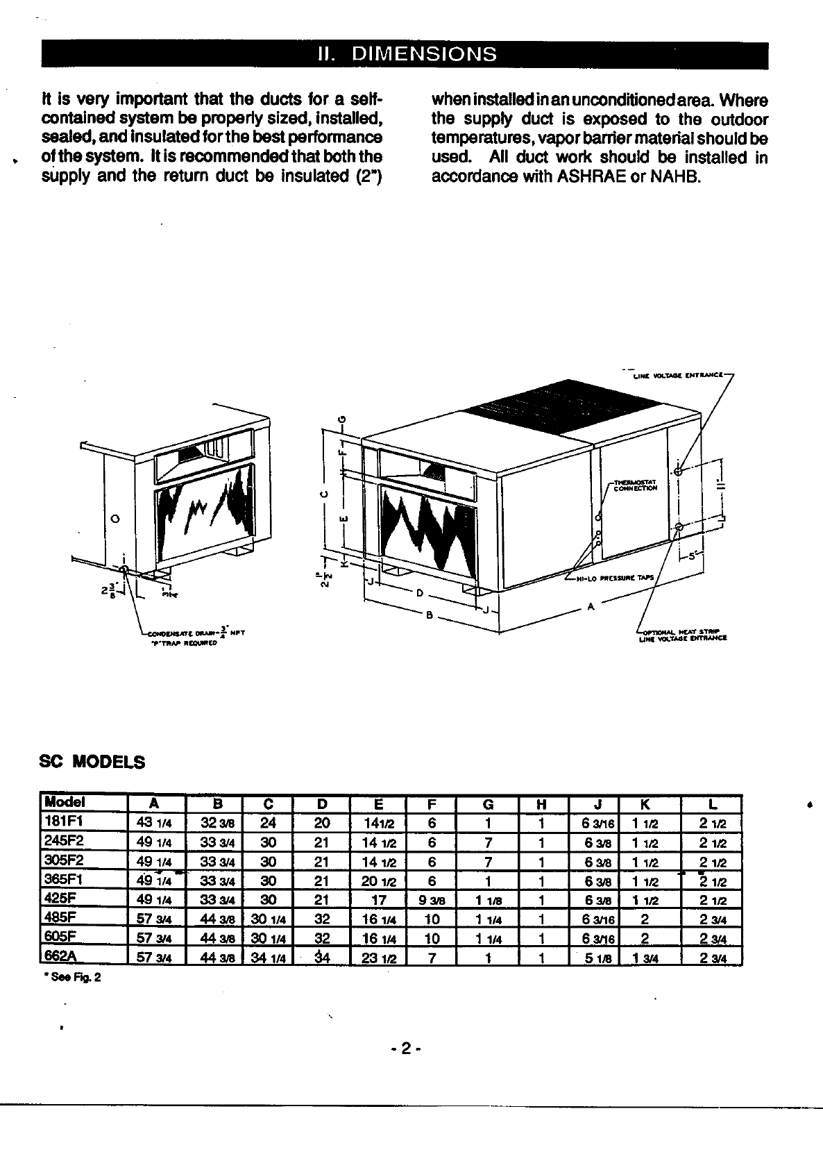
It is very important that the ducts for a self-
contained system be properly sized, installed,
sealed, and insulated for the best performance
ofthe system. It is recommended that boththe
supply and the return duct be insulated (2")
when installedinan unconditionedarea. Where
the supply duct is exposed to the outdoor
temperatures, vapor barrier material should be
used. All duct work should be installed in
accordance with ASHRAE or NAHB.
SC MODELS
Model A B C D E F G
181F1 43 1/4 323/8 24 20 141/2 6 1
245F2 49 1/4 33 3/4 30 21 14 1/2 6 7
305F2 49 1/4 33 3/4 30 21 14 1/2 6 7
365F1 49_/4-- 33 3/4 30 21 201/2 6 1
425F 491/4 333/4 30 21 17 93/8 1 lJ8
485F 573/4 443/8 301/4 32 16114 10 1 114
605F 573/4 44us 301/4 32 161/4 10 1 1/4
662A 573/4 443/8 341/4 _231/2 7 1
"See Rg.2
H
1
1
1
1
1
1
1
1
J K L ,
6_s 1112 21/2
63_ 11/2 21/2
63/8 11/2 21/2
63/8 11/2 21/2
6_ 1 I/2 21/2
63/16 2 23/4
63/16 2 23/4
5lJ8 13/4 23/4
-2-
I
..L
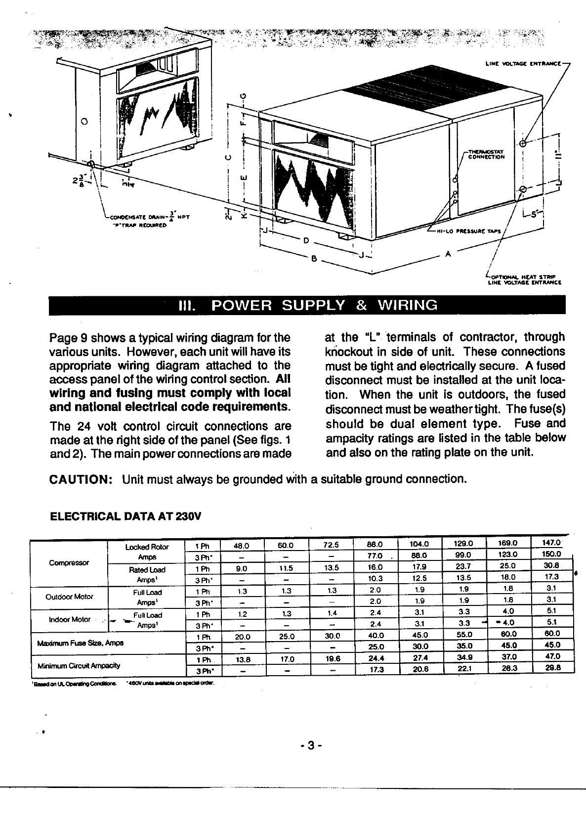
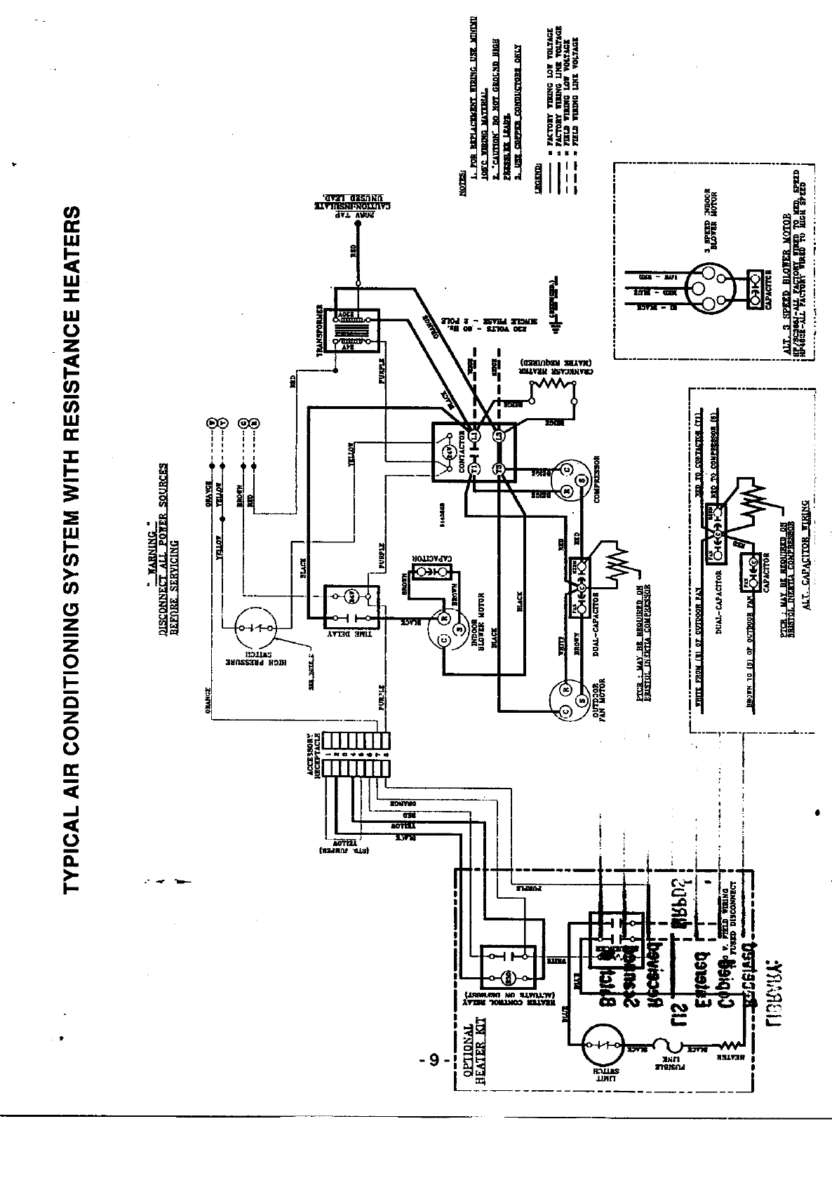
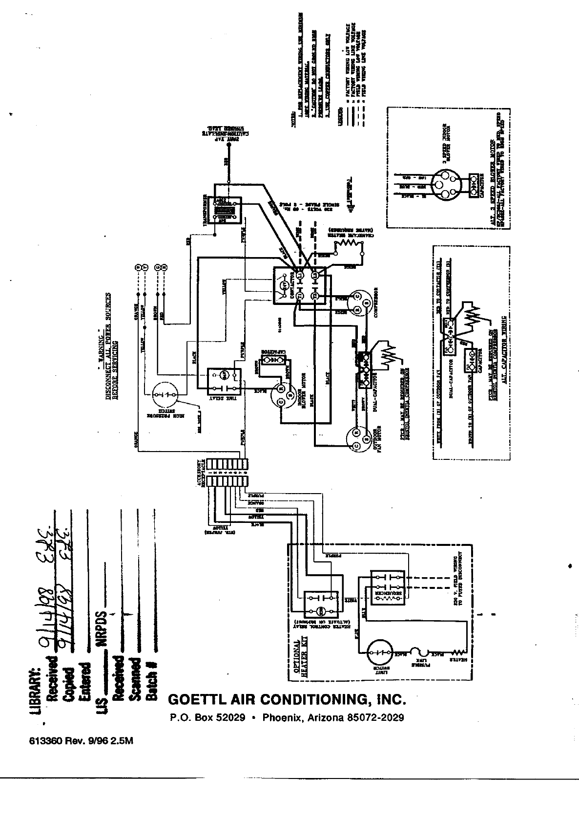
Page 9 shows a typical wiring diagram for the
various units. However, each unit willhave its
appropriate widng diagram attached to the
access panel of the wiring control section. All
wiring and fusing must comply with local
and national electrical code requirements.
The 24 volt control circuit connections are
made at the right side of the panel (See figs. 1
and 2). The main power connections are made
at the "L" terminals of contractor, through
knockout in side of unit. These connections
must be tight and electrically secure. A fused
disconnect must be installed at the unit loca-
tion. When the unit is outdoors, the fused
disconnect must be weather tight. The fuse(s)
should be dual element type. Fuse and
ampacity ratings are listed in the table below
and also on the rating plate on the unit.
CAUTION: Unit must always be grounded Witha suitable ground connection.
ELECTRICAL DATA AT 230V
Compressor
Outdoor Mofor
Indoor Motor
Locked Rotor
Amps
Rated Load
Amps_
Full Load
Amps_
FullLoad
.- _ _.- Amps_
I Ph 48,0
3Ph"
1Ph 9.0
3Ph"
1Ph 1,3
3Ph*
1Ph 1,2
3Ph"
1Ph 20,0
3Ph"
1Ph 13.8
3Ph"
Ma_nurnFuseSize.Am_
M_nimum Cb'cuit Ampacity
60.0
11.5
1.3
1.3
25.0
17.0
m
72.5
13.5
1.3
1,4
30,0
19,8
88.0
7"/'.O .
16.0
10.3
2,0
2,0
2,4
2,4
40.0
25,0
24,4
17.3
104,0 129.0
88.0 99.0
17.9 23.7
12,5 13,5
1.9 1.9
1.9 1,9
3.1 3.3
3.1 3.3
45.0 55.0
30.0 35.0
27.4 34.9
20.6 22.1
169.0
123,0
25,0
18.0
1.8
1,8
4,0
"4.0
60.0
45.0
37.0
28.3
147,0
150.0
30,8
17.3
3.1
3.1
5.1
5.1
60.0
45.0
47.0
29.8
. t
-3-
ROOF" MOUNTED
UNIT
i
I
WALLS
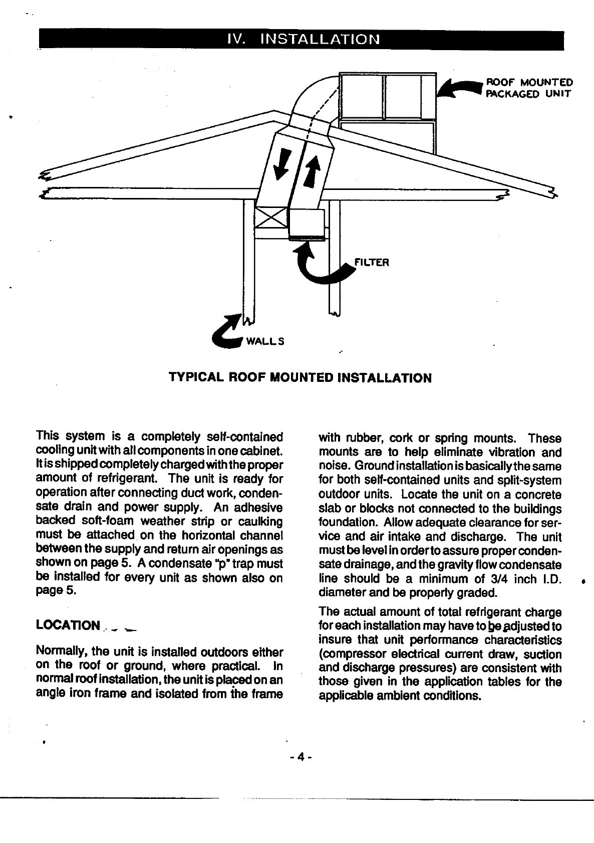
TYPICAL ROOF MOUNTED INSTALLATION
This system is a completely serf-contained
cooling unitwith all components inone cabinet.
Itis shipped completely charged withthe proper
amount of refrigerant. The unit is ready for
operation after connecting duct work, conden-
sate drain and power supply. An adhesive
backed soft-foam weather strip or caulking
must be attached on the horizontal channel
batween the supply and return air openings as
shown on page 5. A condensate =p"trap must
be installed for every unit as shown also on
page 5.
LOCATION .__.,._
Normally, the unit is installed outdoors either
on the roof or ground, where practical. In
normal roof installation, the unit is placed on an
angle iron frame and isolated from the frame
with rubber,cork or spring mounts. These
mounts are to help eliminate vibration and
noise. Groundinstallationis basicallythe same
for both self-contained units and split-system
outdoor units. Locate the unit on a concrete
slab or blocks not connected to the buildings
foundation. Allow adequate clearance for ser-
vice and air intake and discharge. The unit
mustbe level inorder toassure proper conden-
sate drainage, and the gravityflow condensate
line should be a minimum of 3/4 inch I.D.
diameter and be properly graded.
The actual amount of total refrigerant charge
for each installation may have to!}e.adjusted to
insure that unit performance characteristics
(compressor electrical current draw, suction
and discharge pressures) are consistent with
those given in the application tables for the
applicable ambient conditions.
-4-
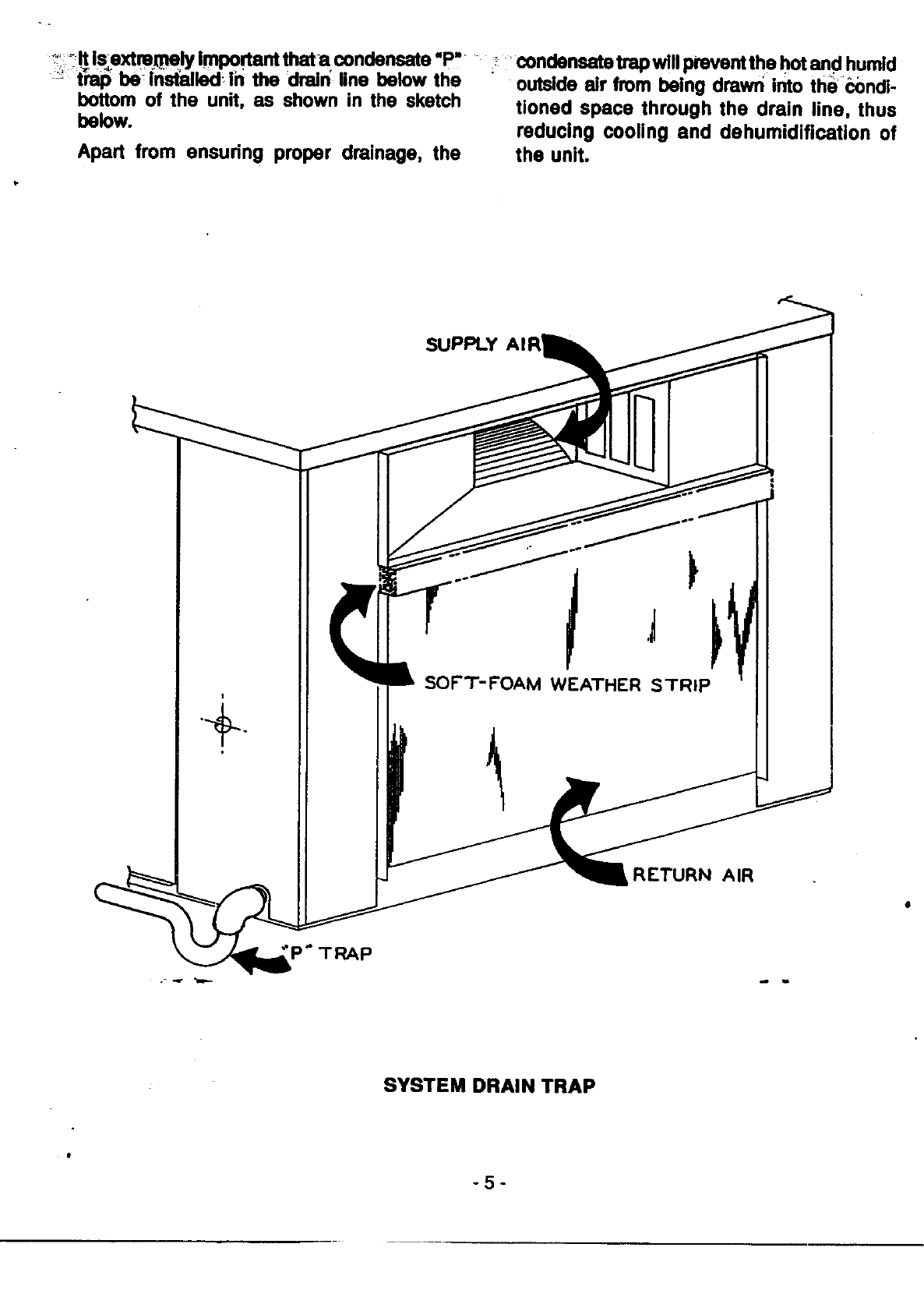
_'___ls_extm_ly important thata condensate "P,
-_ tW be installedi in the drain_line below the
bottom of the unit, as shown in the sketch
below.
Apart from ensudng proper drainage, the
i_ _condensate trap will prevent the hot and humid
outside air from being drawn into the _ndi-
tioned space through the drain line, thus
reducing cooling and dehumidification of
the unit.
÷
P" TRAP
SUPPLY
SOFT-FOAM WEATHER STRIP
RETURN AIR
SYSTEM DRAIN TRAP
-5-
PREUMINARY START-UP
I. If power to unit has been disconnected for
any extended period oftime, restore power
twelve (12) hours prior to start-up proce-
dure.
COOUNG CYCLE CHECK-OUT
PROCEDURE
1. With thermostat calling for cooling and set
10° below room temperature, engage dis-
connect switch(es) to start system.
2. Check the voltage at the compressor motor
connections. If the voltage is 5% below or
10% above the rated voltage or there is a
difference greater than 3% between
phases, shut down the system and callthe
power company. A failure to do so may
cause damage to the equipment.
3. After the unit is in operation, it will take
about 30 minutes running time to Stabilize
the system.
4. In order to check for aproperly working
system, it is recommended that a ther-
mometer be placed inthe return air and one
placed in the a_rsupply. After allinsulating
ofductwork and adjustments ofair registers
are complete, a temperature difference of
15° to 20° is considered satisfactory.
5. When the above Steps are completed, a
check ofvoltage and amperage should be
made of allmotors. These readings should
be within 10% of the performance ratings
given for the spodfic ambients.
6. Suction and discharge pressures should
also be checked to ensure that they agree
reasonably well with the pressures shown
in the catalog for the prevailing ambient
conditions. Also, a suction superheat tern-
perature of 20°F plus or minus 5°F is com-
mon for these unitswhen the outdoor am-
blent is approximately 95°F. This shouldbe
used as a gauge in determining that the
system is not overcharged or has lostsome
of its charge.
7. Finally, the thermostat should be checked
out to assure proper operation. Literature
packed with the thermostat and sub-base
will provide information for this check out.
With the disconnect on "ON" position,voltage
is supplied to the primary ofthe control trans-
former and crankcase heater. The control
transformer reduces the voltage from 230 or
208 to 24 volts for the low voltage and the
thermostat circuit. With a single-stage cool/
single-stage beaLthermostat set in the cooling
position, current is supplied from one side of
the 24 volt secondary ofthe controltransformer
tothe"R"terminalof the thermostat. The other
side of this transformer connects to the main
contractor coil through the high pressure con-
trol. When the thermostat calls for "COOL-
ING", current from the "R" terminal is switched
on to the "Y" terminal causing the compressor
contactor to be energized. The main contactor
closes the contacts inthe high voltage circuit.
The completion of thiscircuit will start both the
outdoor fan motor and the compressor.
The indoor fan relay which is intemally wired
from"G"to"Y" inthethermostatsub-base is also
energized and startsthe indoor fan motor. The
system will operate normallyand begin to cool.
0
|
-6-
Resistance heatersare available as an op-
tional field-installed accessory for air condi-
tioners. Consult factory if resistance heaters
are needed, as a differentthermostator sub
base may be required.
1. Be sure the filter is clean. Inspect every 30
days of operation; if obstructed, clean or
replace filter at once. DO NOT RUN WITH-
OUT AFILTER.
2. Always let the thermostat control the
operation of the system. Never try to =sec-
ond guess" the thermostat, or tamper with
it. Just set the thermostat at the comfort
level desired AND LEAVE IT ALONE. If it
gets too chilly, just turn the thermostat
up a degree at a time untilthe desired level
is achieved. Don't turn the thermostat back
and forth.
3. Air conditioners cannot cool off a house as
fast as a furnace heats it. It pulls the
temperature down slowly. Therefore, do
notturn on and expect immediate action. It
may take a day or so to pull down a hot,
moist house when the unit is first installed,
especially after it has been =soaked"in 100-
110 ° ambient for days.
4. Keep both the evaporator and condenser
coil surfaces clean. Accumulation of dirt
will restrict the air flow and reduce the
performance of your unit.
5. Keep condensate drain lines clear and
clean. All blower fan motors are factory
lubricated and require no attention. The
compressor is hermetically sealed, requir-
ing no attention.
6. Your new air conditioner is mounted out-
doors. Iti_ _-od practice to treat it just as
you would your automobile if it was ex-
posed to the elements constantly; an occa-
sional coat ofwax willgive added protection
against the elements.
.
.
Your new air conditioner compressor is
equipped with a Permanent Split Capacitor
motor. Therefore, ALWAYS WAIT AT
LEAST THREE MINUTES AFTER SHUT-
TING UNIT OFF BEFORE TRYING TO
RESTART. If the unit is started before the
refdgerant pressures have a chance to bal-
ance, the compressor motor may tdp on its
ovedoad, or, invery rare cases, blow a fuse.
Under any normal operation, this will not
happen. It is most likely to happen if a
thermostat is chattering, or if the unit is
started too quickly. Do not be alarmed if
thishappens. Justletthe pressures balance
out and then start the unit.
It is a good practice when there isa power
outage, especially dudng severe thunder
storms,to switchoff your unitat the thermo-
stat until the electdcal power has been
permanently restored. This could prolong
the life of your compressor.
IMPORTANT - READ CAREFULLY
.Your new air conditioner contains a special
compressor warming electrical circuit to
keep the compressor warm dudng long off
periods. Do not be alarmed ifthis creates a
light =humming"sound while the unit is not
running. The "hum"may or may not occur.
Whenever the power has been discon-
nected from the unit for longer than twelve
hours, be sure to turn the power back on
twelve hours before starting the unit. This
will give the compressor warming circuit a
chance to operate and protect the com-
pressor from damage.
J
-7-
HOWTO GET THE MAXIMUM PLEASURE _ture is about the same but there is discomfort.
FROM YOUR AIR CONDmONER
In order that you may fully enjoy the comfort
your Air Conditioner can bring you, an under-
standing of the basic principles involved are
outlined in the following paragraphs.
This is because the humidityis high.
Indoors, the air should be beth cool and rela-
tively dry for comfort. Therefore, the cooling
unit has been designed to remove beth heat
and moisture.
HEATING LOAD:
Any residential cooling system is the reverse of
a heating system. Family livinghabitsthat help
the heating system hurt the cooling system.
The heat pump, fumace, or boiler delivers heat
into the rooms and the heat that is created
within the house from electric lights, cooking,
the TV set, etc. helps to heat the rooms -
therefore, that much less heat is required from
the boiler, furnace, or heat pump.
Cooling is just the reverse. The cooling
equipment removes heat and humidity. Any
extra heat released into the rooms from these
same sources will make the room air warmer
and place an extra burden upon the equip-
ment.
Let's take the heat caused by cooking. For
example, four top burners of a gas range can
produce more heat than a three horsepower air
conditioner can remove. It is much more
practical and economical to ventilate this con-
centrate heat and moisture load than it is to
dispose of itthreugh your air conditioner. Here
is a general rule.
THERMOSTAT SETrlNG:
Forcooling, a temperature of 75 to 78 degrees
is preferred by most people. You may select a
lower temperature setting if you wish and you
will probably have that temperature a good
portionofthe time. But do not be disappointed
and condemn the equipment ifthe temperature
getsa few degrees warmer during hotweather.
Set the thermostat at the temperature agree-
able to the family and leave it there.
Do not be concerned if, in the evening, when
the outside temperature dropsbelowthe inside
temperature, your air conditioning system is
stillrunning. The entire structure of your house
has been soaking up heat from the sun all day
long. After the sun has set there is still a
tremendous amount of heat in the walls, ceil-
ing, roof, furnishings, etc., that must be dis-
posed of before the air conditioner stops run-
ning. Outdoor temperatures can drop rapidly
after sundown, while the house and its fur-
nishings continue to give off heat for several
hours.
INDOOR BLOWER OPERATION
Whenever you plan to have youroven or
range top burners on for more than few
minutes dudng hot weather, close off
the kitchen from the rest of the house,
open a window or outside door, and turn
on your kitchen ventilator.
You can also-effectively reduce the load on
yourcoolingsystem by keepingwindowshades,
blinds,ordrapes closed or byinstallingawnings
or canopies.
There are days when the temperature is rela-
tively high, yet it is comfortable because the air
is dry. This is because the relative humidityis
low. There are other days when the tempera-
I*
To improvethe efficiency ofthe unit, the blower
is operated on atime delay. Depending on the
outside ambient, the blower could delay start-
ing up for 5 to 15 seconds even though the
thermostat calls for cooling. When the ther-
mostat is satisfied, the blower could keep on
runningfor 1/2 to 1-1/2 minutes longer. Do not
be alarmed if you do not hear-tim blower
running immediately after the unit is switched
on.
Your unit is an Air Conditioner. It is producing
cooled air. The cooling which is accomplished
by means of remote controls, is completely
automatic, and requires no attention after set-
ting to the comfort level you desire.
-8-
CT3"-
GOETTL AIR CONDITIONING, INC.
P.O. Box 52029 • Phoenix, Arizona 85072-2029
613360 Rev. 9/96 2.5M
