GOLDSTAR VCR Manual 97110070
User Manual: GOLDSTAR GOLDSTAR VCR Manual GOLDSTAR VCR Owner's Manual, GOLDSTAR VCR installation guides
Open the PDF directly: View PDF ![]() .
.
Page Count: 36
GoldStar
VIDEO CASSETTE RECORDER
OWNER'S MANUAL
Before connecting, operating, or adjusting this product,
please read this instruction booklet carefully and completely.
GVR-F435
WARNING : TO REDUCE THE RISK OF FIRE OR ELECTRIC SHOCK,
DO NOT EXPOSE THIS PRODUCT TO RAIN OR MOISTURE.
CAUTION : TO REDUCE THE RISK
OF ELECTRIC SHOCK,
DO NOT REMOVE COVER (OR BACK);
NO USER-SERVICEABLE PARTS INSIDE
REFER SERVICING TO QUALIFIED SERVICE
PERSONNEL.
This lightning flash with arrowhead symbol
within an equilateral triangle is intended to
alert the user to the presence of uninsulated
dangerous voltage within the product's
enclosure that may be of sufficient magni-
tude to constitute a risk of electric shock to
persons.
The exclamation point within an equilateral
triangle is intended to alert the user to the
presence of important operating and mainte-
nance (servicing) instructions in the literature
accompanying the product.
THIS VIDEO CASSETTE RECORDER SHOULD BE OPER-
ATED WITH AC 120V, 60Hz CURRENT ONLY.
THIS VIDEO DECK IS AVHS TYPE RE-
CORDER. FOR PROPER OPERATION,
USE ONLY A VHS TYPE VIDEO CAS-
SETTE.
lUlQ VHS High Quality technology is incorporated
into VCR's marked HQ.
This unit is compatible with conventional
VHS VCRs.
CAUTION •TO PREVENT ELECTRIC SHOCK, DO NOT
USE THIS (POLARIZED) PLUG WITH AN EXTENSION
CORD, RECEPTACLE OR OTHER OUTLET UNLESS
THE PLUG CAN BE FULLY INSERTED WITHOUT
EXPOSING ANY PARTS OF THE BLADES.
WARNING:
Many television programs and films are copyrighted.In
certain circumstances,copyrightlaw may apply to private
in-homevideotapingof copyrightedmaterials.
FCC WARNING: Thisequipment may generate or use radio
frequency energy.Changes or modificationsto this equip-
ment may cause harmful interferenceunlessthe modifica-
tionsare expresslyapprovedinthe instructionmanual.The
usercouldlosethe authorityto operatethisequipmentif an
unauthorizedchangeor modificationis made.
If you pour a cold liquid into a glass, water vapor in the air
will condense on the surface of the glass. This is moisture
condensation. Moisture condensation on the head drum,
one of the most crucial parts of the unit, will cause
damage to the tape.
When the VCR is exposed to a rapid temperature change
from cold to warm, some condensation will occur. Under
this condition, connect the power cord to the AC line,
press POWER button on and allow at least two hours for
the VCR to dry out.
The serial number is found on the back of this unit.This num-
ber is unique to this unit and not available to others. You
should record requested information here and retain this
guide as a permanent record of your purchase.
Model No. GVR-F435
Serial No.
REGULATORY INFORMATION
This equipment has been tested and found to comply with
the limits for a Class B digital device, pursuant to Part 15 of
the FCC Rules. These limits are designed to provide rea-
sonable protection against harmful interference in a resi-
dential installation! This equipment generates, uses and
can radiate radio frequency energy and, if not installed and
used in accordance with the instructions, may cause harm-
ful interference to radio communications.
However, there is no guarantee that interference will not
occur in a particular installation. If this equipment does
cause harmful interference to radio or television reception,
which can be determined by turning the equipment off and
on, the user is encouraged to try to correct the interference
by one or more of the following measures:
=Reorient or relocate the receiving antenna.
• Increase the separation between the equipment and
receiver.
•Connect the equipment into an outlet on acircuit differ-
ent from that to which the receiver is connected.
• Consult the dealer or an experienced radio/'l-V
technician for help.
This Class (B) digital apparatus meets all requirements of
the Canadian Interference-Causing Equipment Regula-
tions.
Cet appareil num_'rique de ia classe (B) respecte toutes les
exigences du R_glement sur le mat6riel brouilleur du
Canada.
-2-
CONTENTS FEATURES
Features/Accessories............................................................................................3
ImportantSafeguards............................................................................................4
Installation/WiringDiagram....................................................................................6
VCR to TV Connection..........................................................................................6
Antennato VCR Connections...............................................................................7
CableAntenna(CAW) Connections.....................................................................8
VCR OutputChannel Setting................................................................................9
ControlNames and Locations.............................................................................10
RemoteControlUnit............................................................................................12
Onscreen Display(OSD).....................................................................................14
Settingthe OnscreenDisplay..............................................................................15
Channel Selection...............................................................................................16
ViewingTV Only..................................................................................................17
Video CassetteTapes..........................................................................................18
Cassette Loadingand Unloading........................................................................18
Settingthe Clock.................................................................................................19
NormalPlayback.................................................................................................20
Special EffectsPlayback.....................................................................................21
VISSFFIMESearch..............................................................................................23
NormalRecording................................................................................................24
Timer Recording..................................................................................................25
InstantTimer Recording(ITR) .............................................................................28
TapeCounterMemoryFeature ...........................................................................29
Editinga Recording.............................................................................................30
Auto-Rewind........................................................................................................30
PlaybackwithTV EquippedwithVIR ..................................................................30
OperatingHints....................................................................................................30
Camcorderto VCR Dubbingand Editing............................................................31
VCR to VCR Dubbing..........................................................................................31
Troubleshooting...................................................................................................32
Video Head Cleaning...........................................................................................33
Specifications.......................................................................................................34
Warranty.................................................................................................Rear cover
• Double Azimuth 4 Head System
• Quick Response Mechanism
•181 Channel Frequency
Synthesized Cable Compatible
Tuner with Autochannel
Programming and Multichannel
Scan
•1 Year/8 Event Timer with DAILY
and WEEKLY Function
•High Quality (HQ) Picture
Enhancement System for
Improved Image Sharpness
and Detail
•Auto Power and Playback
Functions
•ITR (Instant Timer Recording)
•Real-Time Tape Counter,
Tape Remaining Time
•Jet Search/Logic Search/
CM Scan
•Clean Still, Slow, Frame Advance
•Auto Tracking Function/Auto
Head Cleaner
•VISS (VHS Index Search System)
Function/Time Search
•Onscreen Display of Function
•Trilingual Onscreen Programming
(English/Spanish/French)
ACCESSORIES
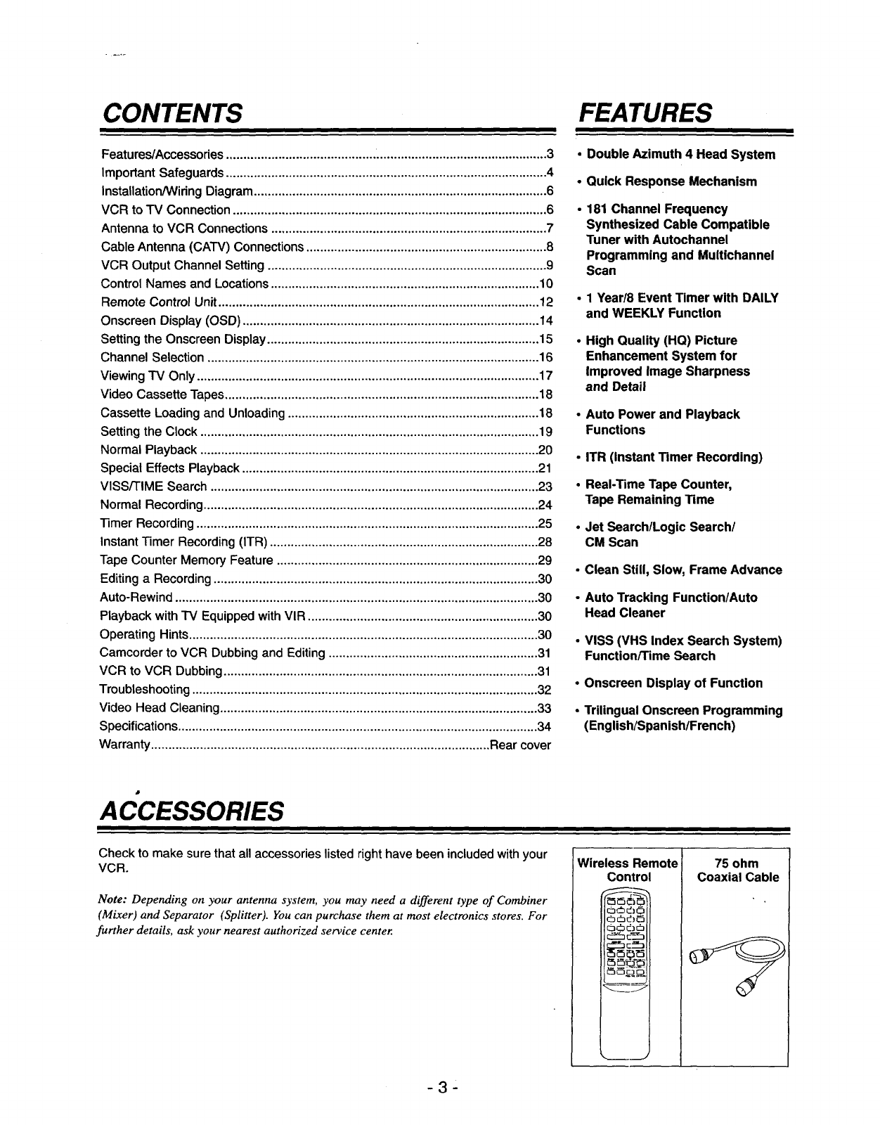
Check to make sure that all accessories listed right have been included with your
VCR.
Note: Depending on your antenna system, you may need a different type of Combiner
(Mixer) and Separator (Splitter). You can purchase them at mast electronics stores. For
further details, ask your nearest authorized service center.
Wireless Remote
Control
OcSd_
_cSd_e5
cS_d_cb
75 ohm
Coaxial Cable
-3-
IMPORTANT SAFEGUARDS
1.
2.
.
4°
5.
6.
7.
8°
Read Instructions -- All the safety and operating
instructionsshouldbe readbefore the product is operat-
ed.
Retain Instructions -- The safety and operating
instructionsshouldbe retained forfuturereference.
Heed Warnings --All warningson the productand in
the operatinginstructionsshouldbe adheredto.
Follow Instructions --All operatingand use instruc-
tionsshouldbe followed.
Cleaning -- Unplugthis productfrom the wall outlet
before cleaning.Do not use liquidcleanersor aerosol
cleaners.Use a dampclothfor cleaning.
Exception:Products meant for continuoususe,such as
a cableconverter,may be left pluggedin.
Attachments -- Do not use attachmentsnot recom-
mendedbythe productmanufactureras theymaycause
hazards.
Water and Moisture -- Do not use this productnear
water,or nearmoistor dampareas.
Accessories -- Do not place this product on an unsta-
ble cart, stand, tripod, bracket, or table. The product may
fall, causing serious injury to a child or adult, and serious
damage to the product. Use only with a cart, stand, tri-
pod, bracket, or table recommended by the manufactur-
er, or sold with the product. Any mounting of the product
should follow the manufacturer's instructions, and
should use a mounting accessory recommended by the
manufacturer.
10.
11.
12.
13.
Ventilation-- Slotsandopeningsinthe cabinet are pro-
vided for ventilationand to ensure reliableoperationof
the productandto protectit from overheating.Andthese
openingsmustnotbe blockedorcovered. The openings
should never be blockedby placingthe producton a
bed, sofa, rug, or other similarsurface. This product
shouldnot be placed in a built-ininstallationsuchas a
bookcaseor rackunlessproperventilationis providedor
the manufacturer'sinstructionshave beenfollowed.
Power Source -- This productshouldbe operatedonly
fromthe type of powersourceindicatedon the marking
label. If youare notsure of the type of power supplyto
your home, consultyour productdealer or local power
company. For productsintendedto operatefrom battery
power, or other source, refer to the operatinginstruc-
tions.
Grounding or Polarization -- This productmay be
equippedwitha polarizedalternating-currentlineplug(a
plug havingone blade widerthan the other).This plug
willfit intothe poweroutletonlyoneway.This is asafe-
ty feature. If you are unableto insertthe plugfully into
the outlet,try reversingthe plug. If the plugshouldstill
fail to fit, contactyour electricianto replaceyourobso-
lete outlet.Donotdefeatthe safetypurposeofthe polar-
ized plug.
Power-Cord Protection -- Power-supply cords should
be routed so that they are not likely to be walked on or
pinched by items placed upon or against them. Pay par-
ticular attention to cords at plugs and the point where
they exit the product.
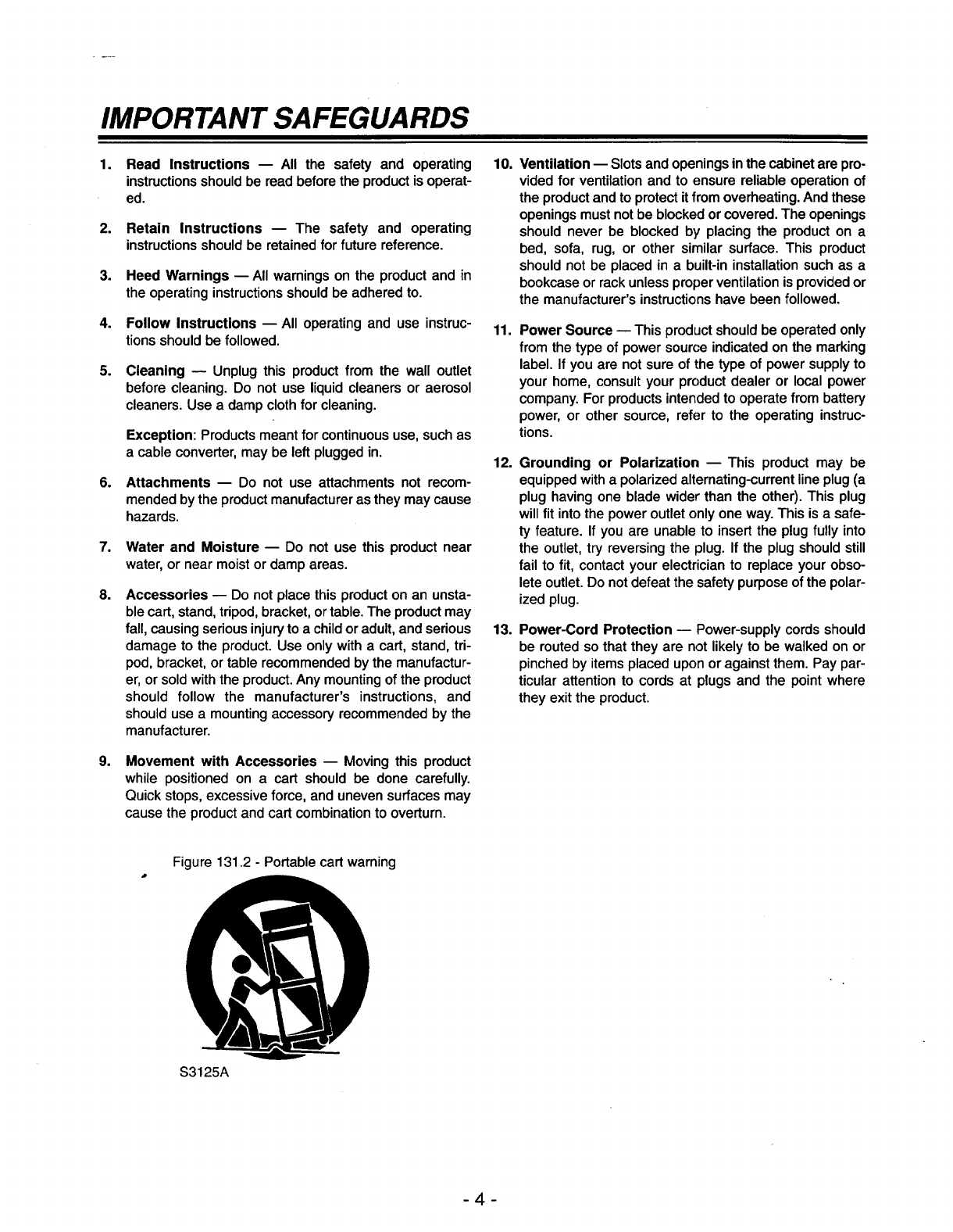
g° Movement with Accessories -- Movingthis product
while positionedon a cart should be done carefully.
Quickstops,excessiveforce, and unevensurfacesmay
causethe productandcart combinationto overturn.
Figure 131.2 -Portable cart warning
S3125A
4
14. Protective Attachment Plug -- This product is 19.
equipped with an attachment plug featuring overload
protection. This is a safety feature. See Instruction
Manual for replacement or resetting of protective device.
If replacement of the plug is required, be sure the ser-
vice technician has used a replacement plug specified
by the manufacturer that has the same overload protec- 20.
tion as the original plug.
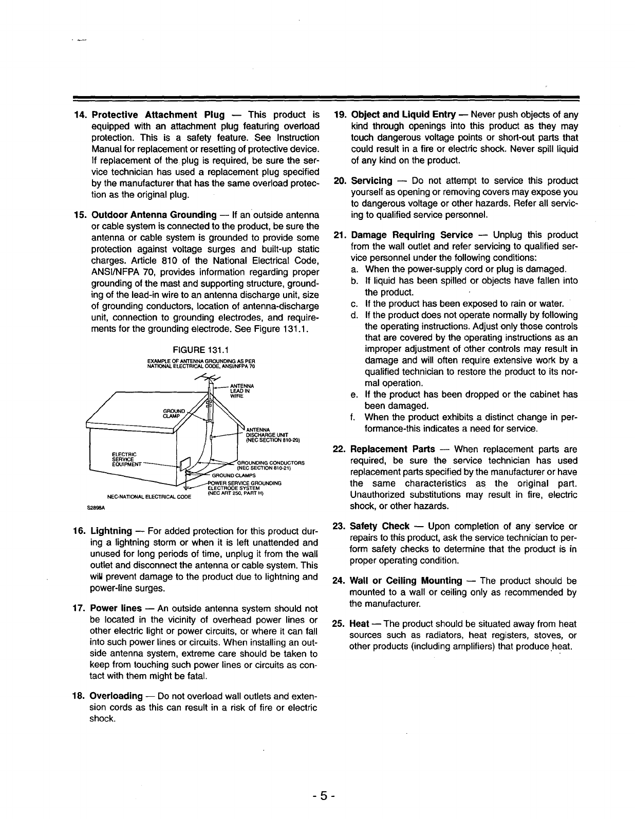
15. Outdoor Antenna Grounding mIf an outside antenna
or cable system isconnected to the product, be sure the
antenna or cable system is grounded to provide some
protection against voltage surges and built-up static
charges. Article 810 of the National Electrical Code,
ANSI/NFPA 70, provides information regarding proper
grounding of the mast and supporting structure, ground-
ing of the lead-in wire to an antenna discharge unit, size
of grounding conductors, location of antenna-discharge
unit, connection to grounding electrodes, and require-
ments for the grounding electrode. See Figure 131.1.
FIGURE 131.1
EXAMPLE OF ANTENNA GROUNDING AS PER
NATIONAL ELECTRICAL CODE, ANSI/NFPA 70
ANTENNA
L_IN
WIRE
g_D
ANTENNA
_.-_ DISCHARGE UNIT
(NEC SECTION 810-20)
_GROUNDING CONDUCTORS
J(NEC SECTION 810-21)
GROUND CLAMPS
WER SERVICE GROUNDING
-_ ELECTRODE SYSTEM
NEC-NATIONAL ELECTRICAL CODE (NEC ART 250, PART H)
$2896A
16. Lightning h For added protection for this product dur-
ing a lightning storm or when it is left unattended and
unused for long periods of time, unplug it from the wall
outlet and disconnect the antenna or cable system. This
wiU prevent damage to the product due to lightning and
power-line surges.
17. Power lines -- An outside antenna system should not
be located in the vicinity of overhead power lines or
other electric light or power circuits, or where it can fall
into such power lines or circuits. When installing an out-
side antenna system, extreme care should be taken to
keep from touching such power lines or circuits as con-
tact with them might be fatal.
18. Overloading -- Do not overload wall outlets and exten-
sion cords as this can result in a risk of fire or electric
shock.
21.
22.
23.
24.
25.
Object and Liquid Entry p Never push objects of any
kind throughopeningsinto this productas they may
touch dangerousvoltagepointsor short-outpartsthat
couldresultin a fire or electricshock.Never spillliquid
of any kindonthe product.
Servicing m Do not attempt to service this product
yourself as opening or removing covers may expose you
to dangerous voltage or other hazards. Refer all servic-
ing to qualified service personnel.
Damage Requiring Service -- Unplug this product
from the walloutlet and referservicing to qualified ser-
vice personnelunderthe following conditions:
a. When the power-supplycord or plugis damaged.
b. If liquidhas been spilledor objectshave fallen into
the product.
c. If the producthas beenexposedto rainor water.
d. If the productdoesnotoperatenormallyby following
the operatinginstructions.Adjust onlythosecontrols
that are coveredby the operatinginstructionsas an
improperadjustmentof other controlsmay resultin
damage and will often requireextensivework by a
qualifiedtechnicianto restorethe productto its nor-
mal operation.
e. If the producthas beendroppedor the cabinet has
beendamaged.
f. When the productexhibitsa distinctchangein per-
formance-this indicatesaneedfor service.
Replacement Parts _When replacement parts are
required, be sure the service technician has used
replacement parts specified by the manufacturer or have
the same characteristics as the original part.
Unauthorized substitutions may result in fire, electric
shock, or other hazards.
Safety Check -- Upon completion of any service or
repairs tothis product, ask the service technicianto per-
form safety checksto determinethat the productis in
properoperatingcondition.
Wall or Ceiling Mounting -- The productshould be
mountedto a wall or ceilingonly as recommendedby
the manufacturer.
Heat -- The product should be situated away from heat
sources such as radiators, heat registers, stoves, or
other products (including amplifiers) that produce heat.
-5-
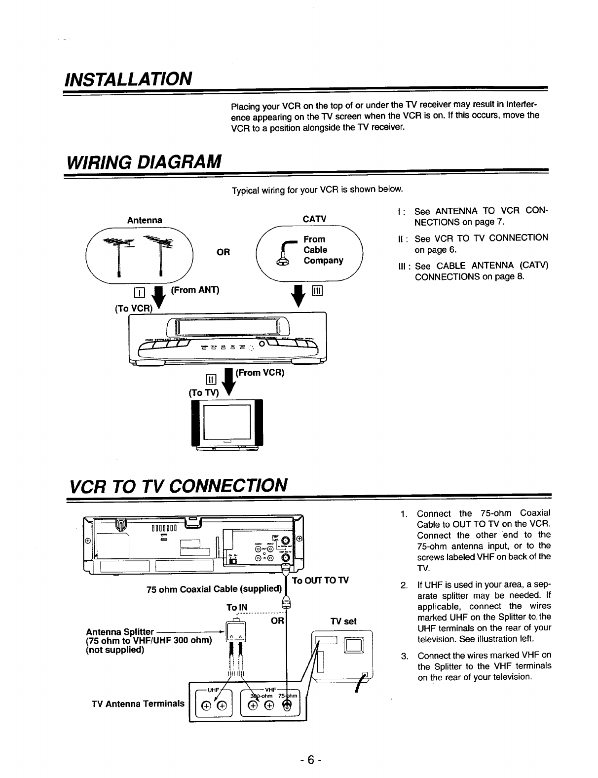
INSTALLATION
Placing your VCR on the top of or under the IV receiver may result in interfer-
ence appearing on the IV screen when the VCR is on. If this occurs, move the
VCR to a position alongside the TV receiver.
WIRING DIAGRAM
Typical wiring for your VCR is shown below.
Antenna CATV
_T__ OR _[ FcOb/e "_
Companyy
VCR -!)v (From ANT)
(To
[] l(From VCR)
(To TV)
I: See ANTENNA TO VCR CON-
NECTIONS on page 7.
I1: See VCR TO IV CONNECTION
on page 6.
II1: See CABLE ANTENNA (CATV)
CONNECTIONS on page 8.
VCR TO TV CONNECTION
75 ohm Coaxial Cable (supplied)
Antenna Splitter
(75 ohm to VHF/UHF 300 ohm)
(not supplied)
TV Antenna Terminals ___
To OUT TO TV
TV set
1.
2,
3,
Connect the 75-ohm Coaxial
Cable to OUT TO TV on the VCR.
Connect the other end to the
75-ohm antenna input, or to the
screws labeled VHF on back of the
"IV.
If UHF is used in your area, a sep-
arate splitter may be needed. If
applicable, connect the wires
marked UHF on the Splitter to.the
UHF terminals on the rear of your
television. See illustration left.
Connect the wires marked VHF on
the Splitter to the VHF terminals
on the rear of your television.
-6-
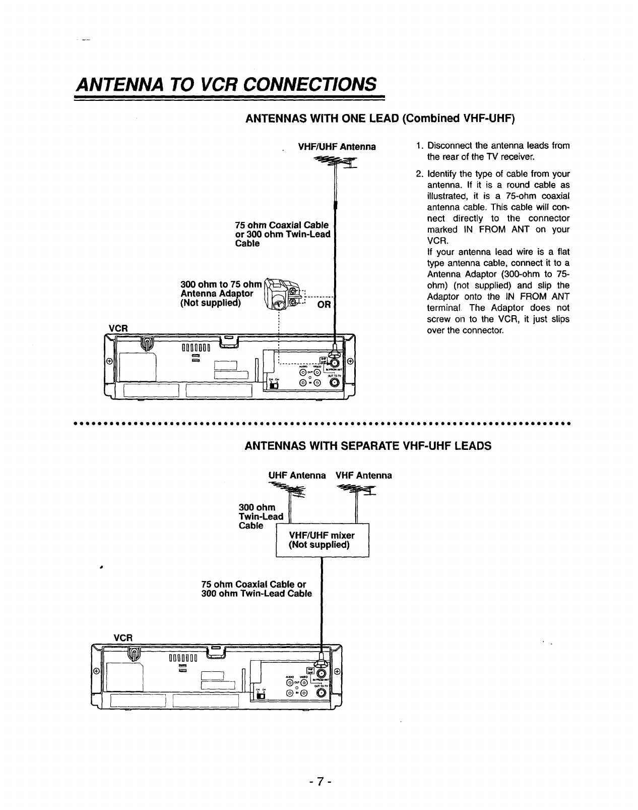
ANTENNA TO VCR CONNECTIONS
ANTENNAS WITH ONE LEAD (Combined VHF-UHF)
VHF/UHF Antenna
75 ohm Coaxial Cable
or 300 ohm Twin-Lead
Cable
300 ohm to 75 ohm
Antenna Adaptor Jl 1_-_:. .........
(Not supplied) k_L.: OR
VCR
1.
2.
Disconnect the antenna leads from
the rear of the TV receiver.
Identify the type of cable from your
antenna. If it is a round cable as
illustrated, it is a 75-ohm coaxial
antenna cable. This cable will con-
nect directly to the connector
marked IN FROM ANT on your
VCR.
If your antenna lead wire is a flat
type antenna cable, connect it to a
Antenna Adaptor (300-ohm to 75-
ohm) (not supplied) and slip the
Adaptor onto the IN FROM ANT
terminal The Adaptor does not
screw on to the VCR, it just slips
over the connector.
IIO0000110001410001tOOOOItOOOOQOOOOQ@OOOQOOOOOOOeOOOOOIOOOQOO0@O0@OO0000@O00QOeOOOIOOIQO
ANTENNAS WITH SEPARATE VHF-UHF LEADS
VCR
%_ ODnI1DO0
-, i
UHFAntenna VHFAntenna
300 ohm_ _r_
TawblneLei IiHF/UHpFpmiei_rll
75 ohm Coaxial Cable or
300 ohm Twin-Lead Cable
-7-
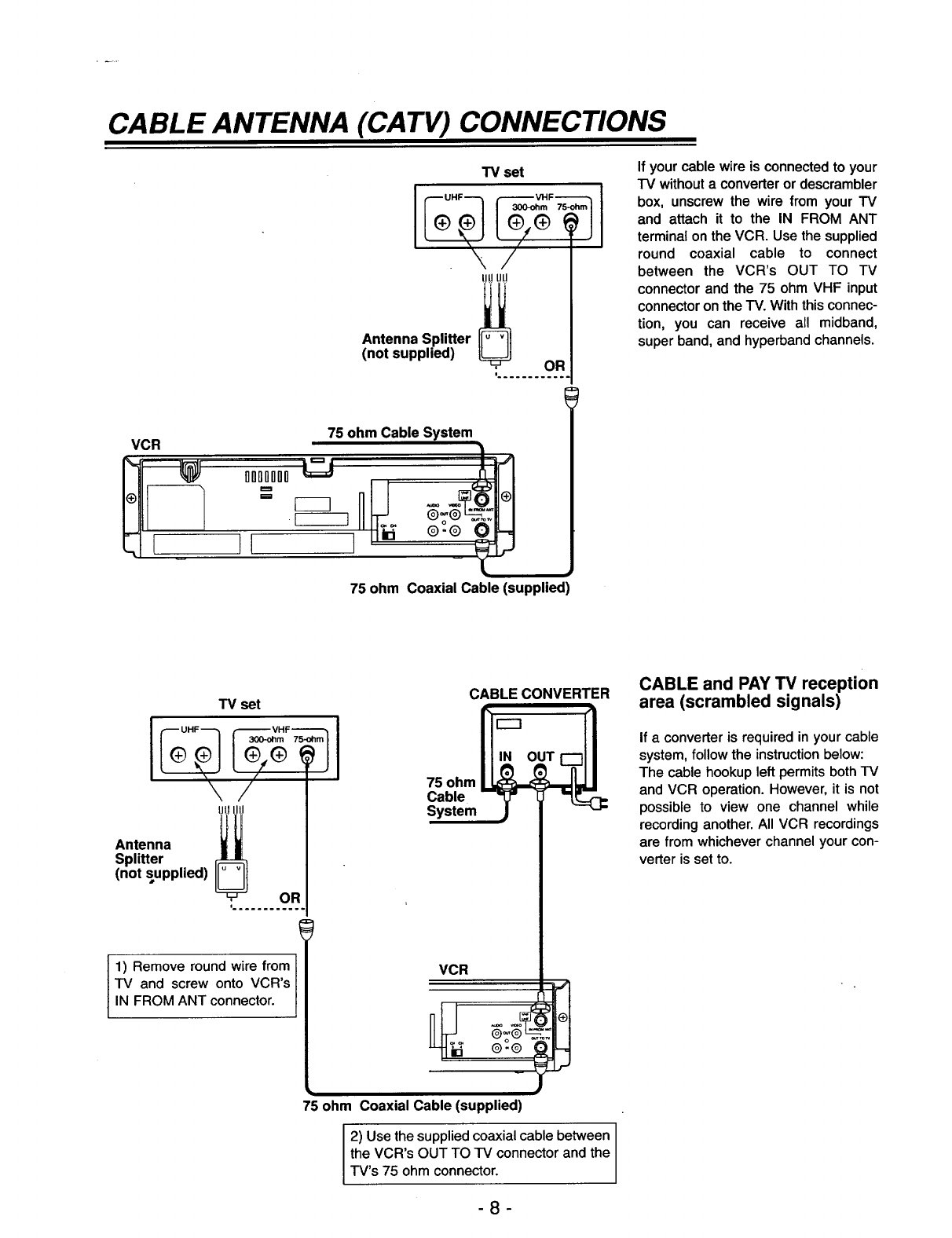
CABLE ANTENNA (CA TV) CONNECTIONS
VCR
--1 1
• _
.E_B
"IV set
Antenna Splitter i_
(not supplied) :........oR.
75 ohm Cable System
75 ohm Coaxial Cable (supplied)
If your cable wire is connected to your
"IV without a converter or descrambler
box, unscrew the wire from your TV
and attach it to the IN FROM ANT
terminal on the VCR. Use the supplied
round coaxial cable to connect
between the VCR's OUT TO TV
connector and the 75 ohm VHF input
connector on the TV. With this connec-
tion, you can receive all midband,
super band, and hyperband channels.
TV set
Antenna :; I
Splitter
(not supplied)
:........95.
1) Remove round wire from
TV and screw onto VCR's
IN FROM ANT connector.
CABLE CONVERTER
75 ohm
Cable
System
VCR
75 ohm Coaxial Cable (supplied)
2) Use the supplied coaxial cable between
the VCR's OUT TO TV connector and the
TV's 75 ohm connector.
-8-
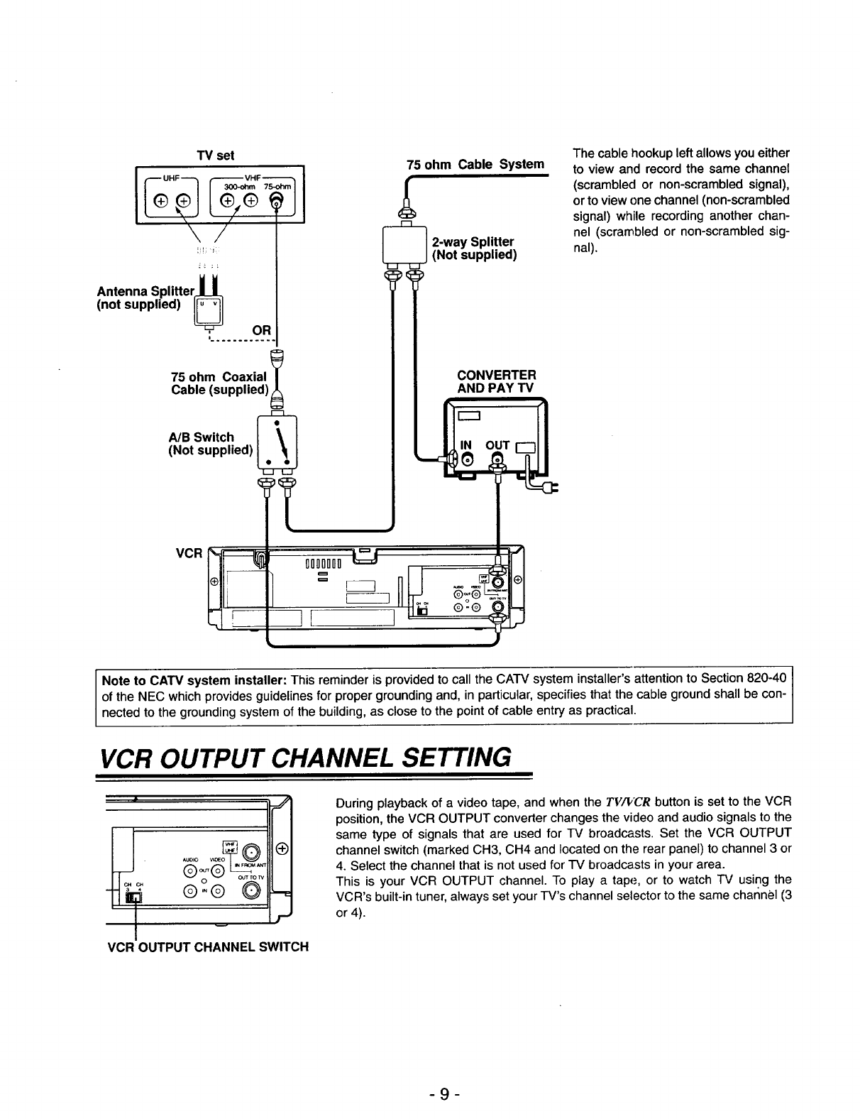
CABLE and PAY TV reception
area (scrambled signals)
If a converter is required in your cable
system, follow the instruction below:
The cable hookup left permits both TV
and VCR operation. However, it is not
possible to view one channel while
recording another. All VCR recordings
are from whichever channel your con-
verter is set to.
TV set
\j "
Antenna Splitter H
(not supplied) _OR
i............
75 ohm Coaxial
Cable (supplied) _
A/B Switch
(Not supplied)
VCR
75 ohm Cable System
_2-way Splitter
(Not supplied)
CONVERTER
AND PAY TV
il I _
i
The cable hookup left allows you either
to view and record the same channel
(scrambled or non-scrambled signal),
or to view one channel (non-scrambled
signal) while recording another chan-
nel (scrambled or non-scrambled sig-
nal).
Note to CATV system installer: This reminder is provided to call the CATV system installer's attention to Section 820-40 I
I
of the NEC which provides guidelines for proper grounding and, in particular, specifies that the cable ground shall be con- I
nected to the grounding system of the building, as close to the point of cable entry as practical.
VCR OUTPUT CHANNEL SETTING
AUDIO V=C_EO
otrr _UTrOW
- ©,.®
F
VCR OUTPUT CHANNEL SWITCH
During playback of a video tape, and when the TV_'€R button is set to the VCR
position, the VCR OUTPUT converter changes the video and audio signals to the
same type of signals that are used for TV broadcasts. Set the VCR OUTPUT
channel switch (marked CH3, CH4 and located on the rear panel) to channel 3 or
4. Select the channel that is not used for TV broadcasts in your area.
This is your VCR OUTPUT channel. To play a tape, or to watch TV using the
VCR's built-in tuner, always set your TV's channel selector to the same char_nel (3
or 4).
-9-
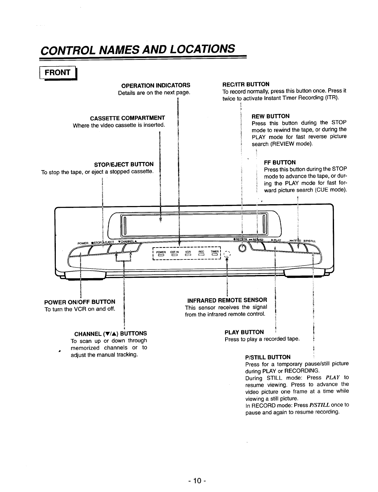
CONTROL NAMES AND LOCATIONS
IFRONT
OPERATION INDICATORS
Details are on the next page.
CASSETTE COMPARTMENT
Where the videocassetteis inserted.
STOP/EJECT BUTTON
To stop the tape, or eject a stopped cassette.
|
POWER ON/OFF BUTTON
To turn the VCR on and off.
CHANNEL (y/A) BUTTONS
To scan up or down through
memorized channels or to
adjust the manual tracking.
REC/ITR BUTTON
To record normally, press this button once. Press it
twice to activate Instant Timer Recording (ITR).
REW BUTTON
Press this button during the STOP
mode to rewind the tape, or during the
PLAY mode for fast reverse picture
search (REVIEW mode).
FF BUTTON
Press this button during the STOP
mode to advance the tape, or dur-
ing the PLAY mode for fast for-
ward picture search (CUE mode).
J
INFRARED REMOTE SENSOR
This sensor receives the signal
from the infrared remote control.
PLAY BUTTON
Press to play a recorded tape.
II P/STILL
P/STILL BUTTON
Press for a temporary pause/still picture
during PLAY or RECORDING.
During STILL mode: Press PLAY to
resume viewing. Press to advance the
video picture one frame at a time while
viewing a still picture.
In RECORD mode: Press P/STILL once to
pause and again to resume recording.
-10-
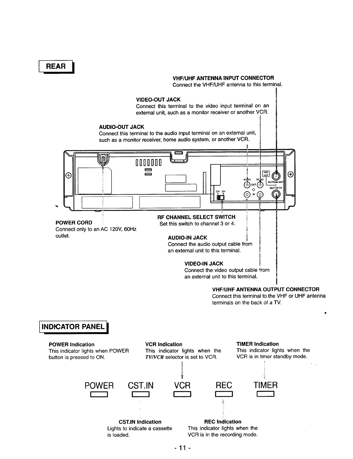
VHF/UHF ANTENNA INPUT CONNECTOR
Connect the VHF/UHF antenna to this terminal.
VIDEO-OUT JACK
Connect this terminalto the video input terminal on an
externalunit,suchas a monitorreceiveror anotherVCR.
AUDIO-OUT JACK
Connect this terminal to the audio input terminal on an external unit,
such as a monitor receiver, home audio system, or another VCR.
°1
"'-L
I
IIIIIII
RF CHANNEL SELECT SWITCH
vv OUT'rOW
O
g"9 @
i
!
i
!
POWER CORD
Connect only to an AC 120V, 60Hz
outlet.
Set this switch to channel 3 or 4.
AUDIO-IN JACK [
Connect the audio output cable from
an external unit to this terminal.
VIDEO-IN JACK
i
!
_J
Connect the video output cable from
an external unit to this terminal.
t INDICATOR PANEL i
VHF/UHF ANTENNA OUTPUT CONNECTOR
Connect this terminal to the VHF or UHF antenna
terminals on the back of a TV.
POWER Indication
This indicator lights when POWER
button is pressed to ON.
POWER
VCR Indication
This indicator lights when the
TV/VCR selector is set to VCR.
,i
CST.IN VCR REC
TIMER Indication
This indicator lights when the
VCR is in timer standby mode.
TIMER
CST.IN Indication
Lights to indicate a cassette
is loaded.
ii
[
REC Indication
This indicator lights when the
VCR is in the recording mode.
-11 -
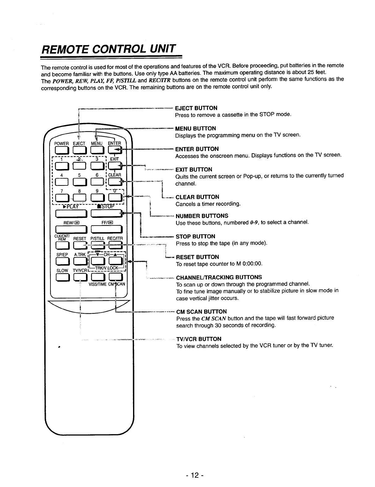
REMOTE CONTROL UNIT
The remote control is used for most of the operations and features of the VCR. Before proceeding, put batteries in the remote
and become familiar with the buttons. Use only type AA batteries. The maximum operating distance is about 25 feet.
The POWER, REW, PLAY, FF,, P/STILL and RE€/ITR buttons on the remote control unit perform the same functions as the
corresponding buttons on the VCR. The remaining buttons are on the remote control unit only.
C3 C3 C3 x,__
F1 .2_. 3 ',
4 5 ;CLEAR
r-q C3 r-q_C2P
78 9 _'-'0"-'1
C3_ C3 El"
•-.--_p_?-= .... _--"
I II 41,-
REW/_q FF/_
I II I
CLRK/ECMNT/RESET P/STILL REC/ITR
SP/EPA.TRKr_'_--CR--'_
CZ]C3',IL.J L..JI
SLOWTVNCRL_-!-R_&££E--'--
C3 _ C3 C3
' VISS/TIME CMpAN
I
EJECT BUTTON
Press to remove a cassette in the STOP mode.
MENU BUTTON
Displays the programming menu on the TV screen.
ENTER BUTTON
Accesses the onscreen menu. Displays functions on the TV screen.
EXIT BUTTON
Quits the current screen or Pop-up, or returns to the currently turned
channel.
_-_ CLEAR BUTTON
Cancels atimer recording.
-1 [....
t
t
NUMBER BUTTONS
Use these buttons, numbered 0-9, to select a channel.
STOP BUTTON
Press to stop the tape (in any mode).
RESET BUTTON
To reset tape counter to M 0:00:00.
.......... CHANNEL/TRACKING BUTTONS
To scan up or down through the programmed channel.
To fine tune image manually or to stabilize picture in slew mode in
case vertical jitter occurs.
CM SCAN BUTTON
Press the CM SCAN button and the tape will fast forward picture
search through 30 seconds of recording.
................... TV/VCR BUTTON
To view channels selected by the VCR tuner or by the TV tuner.
j
-12-
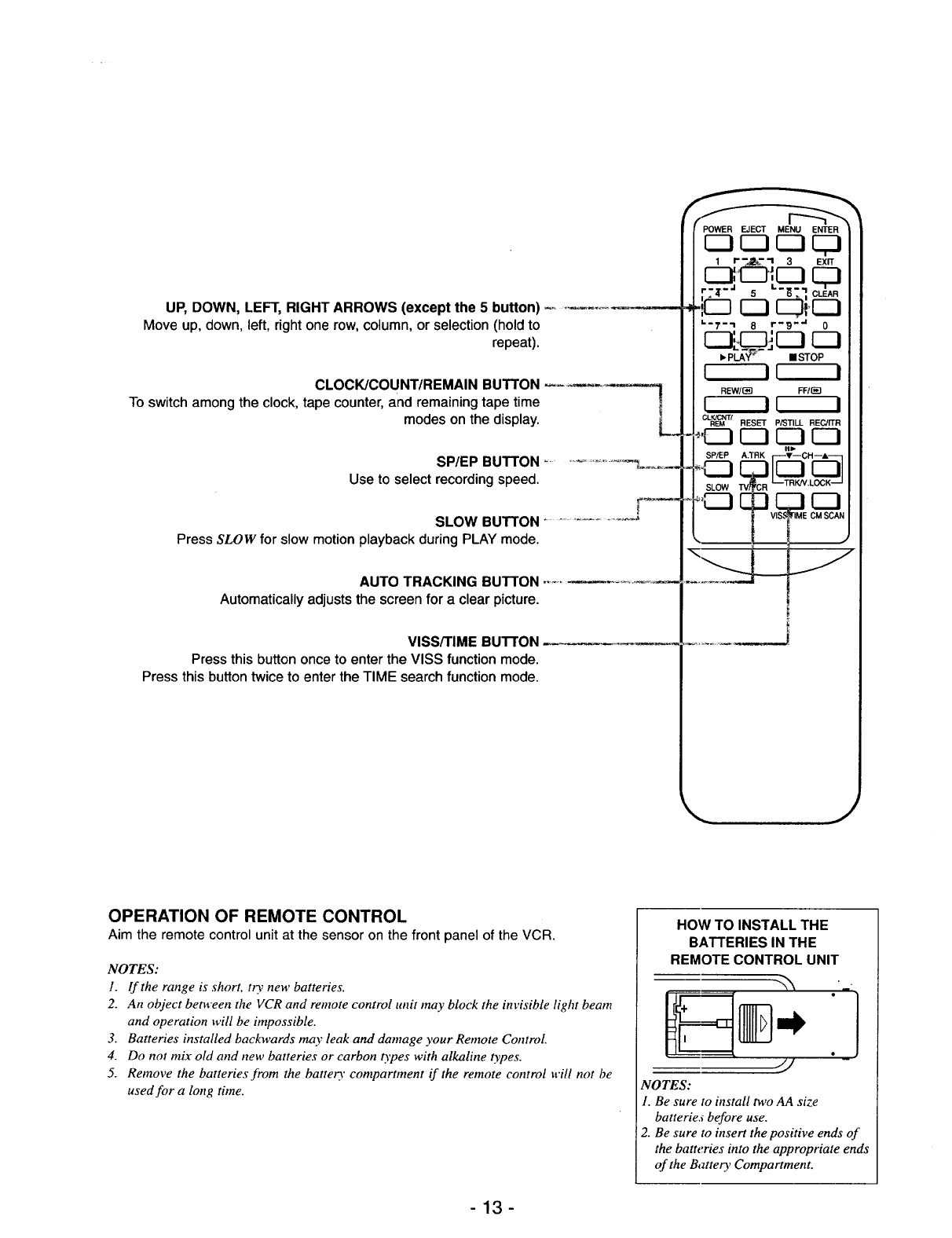
UP, DOWN, LEFT, RIGHT ARROWS (except the 5 button)
Move up, down, left, right one row, column, or selection (hold to
repeat).
CLOCK/COUNT/REMAIN BUTTON
To switch among the clock, tape counter, and remaining tape time
modes on the display.
SP/EP BUTTON ..................... _o_
Use to select recording speed.
SLOW BUTTON .......................
Press SLOW for slow motion playback during PLAY mode.
AUTO TRACKING BUTTON
Automatically adjusts the screen for a clear picture.
VISS/TIME BUTTON
Press this button once to enter the VISS function mode.
Press this button twice to enter the TIME search function mode.
POWER EJECT MENU ENTER
1 I- -_- -I 3 EXIT
' Z"_" 5"_-] Ct_AR
cJi.cJ
_-T-_ 8r'_ -'a 0
• Pt.A-__- • STOP
I II I
REW/(_] FFIr_
I II I
CLEK_M /RESET P/STILL REC/ITR
OPERATION OF REMOTE CONTROL
Aim the remote control unit at the sensor on the front panel of the VCR.
NOTES:
1. If the range is short, t0, new batteries.
2. An object between the VCR and remote control unit may block the invisible light beam
and operation will be impossible.
3. Batteries installed backwards may leak and damage your Remote Control.
4. Do not mix old and new batteries or carbon t)'pes with alkaline types.
5. Remove the batteries from the batte13" compartment if the remote control will not be
used for a long time.
HOW TO INSTALL THE
BATTERIES IN THE
REMOTE CONTROL UNIT
NOTES:
1. Be sure to install two AA size
batteries before use.
2. Be sure to insert the positive ends of
the batteries into the appropriate ends
of the Battery Compartment.
-13-
ONSCREEN DISPLAY
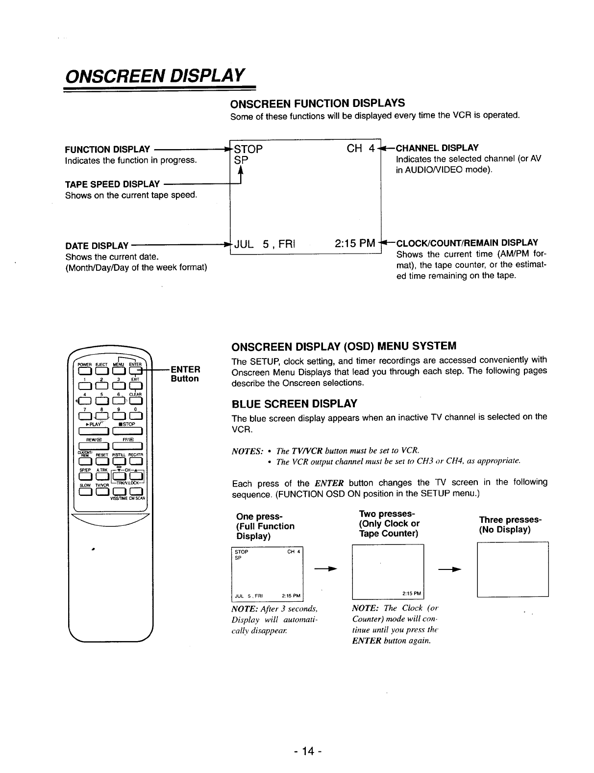
ONSCREEN FUNCTION DISPLAYS
Some of these functions will be displayed every time the VCR is operated,
FUNCTION DISPLAY
Indicates the function in progress.
TAPE SPEED DISPLAY
Shows on the current tape speed.
DATE DISPLAY
Shows the current date.
(Month/Day/Day of the week format)
ISTOP
SP
t
CH
JUL 5, FRI 2:15 PM-
4- =P-CHANNEL DISPLAY
Indicates the selected channel (or AV
in AUDIO/VIDEO mode).
qP'-'CLOCK/COU NT/REMAIN DISPLAY
Shows the current time (AM/PM for-
mat), the tape counter, or the estimat-
ed time remaining on the tape.
POWER EJECT MENU ENTER
C3 C_ r-1 C_-
IZ3 I_
P.PLA_ t mSTOP
rIi r--ii
REW/_ FF/_
rI-i r-I-i
cIJ_l RESET pP3]3LL RECJITR
_IT[_'L_KK_SP/EPA.TRK _T--CHIA_
IZ2 CZI_ _
VISS_IME CMSCAN
•J
_ENTER
Bu_on
ONSCREEN DISPLAY (OSD) MENU SYSTEM
The SETUP, clock setting, and timer recordings are accessed conveniently with
Onscreen Menu Displays that lead you through each step. The following pages
describe the Onscreen selections.
BLUE SCREEN DISPLAY
The blue screen display appears when an inactive TV channel is selected on the
VCR.
NOTES: •The TV/VCR button must be set to VCR.
•The VCR output channel must be set to CH3 or CH4, as appropriate.
Each press of the ENTER button changes the TV screen in the following
sequence. (FUNCTION OSD ON position in the SE'IUP menu.)
One press-
(Full Function
Display)
JUL 5, FRI
NOTE: After 3 seconds,
Display will automati-
cally disappear
Two presses-
(Only Clock or
Tape Counter)
2:15 PM
NOTE: The Clock (or
Counter) mode will con-
tinue until you press the'
ENTER button again.
Three presses-
(No Display)
-14-
SETTING THE ONSCREEN DISPLAY
i i
r------7 r-----i
REW/(_ FF/0_
r------! r-----i
--_k'_l RESET P/STILL REC/ITR
SLOW TVNCR _-TRKN,LOC!K
_ E_3E_3CZ3
VISS/FIME CM SCAN
MENU Button
-ENTER
Button
EXIT Button
•UP, DOWN,
LEFT, RIGHT
Arrows (except
the 5 Button)
Press MENU.
CLOCK
PROGRAM
TUNING
SETUP
SELECT _ENTER
TO EXIT PRESS
Press UP/DOWN and ENTER
button to desired menu.
r
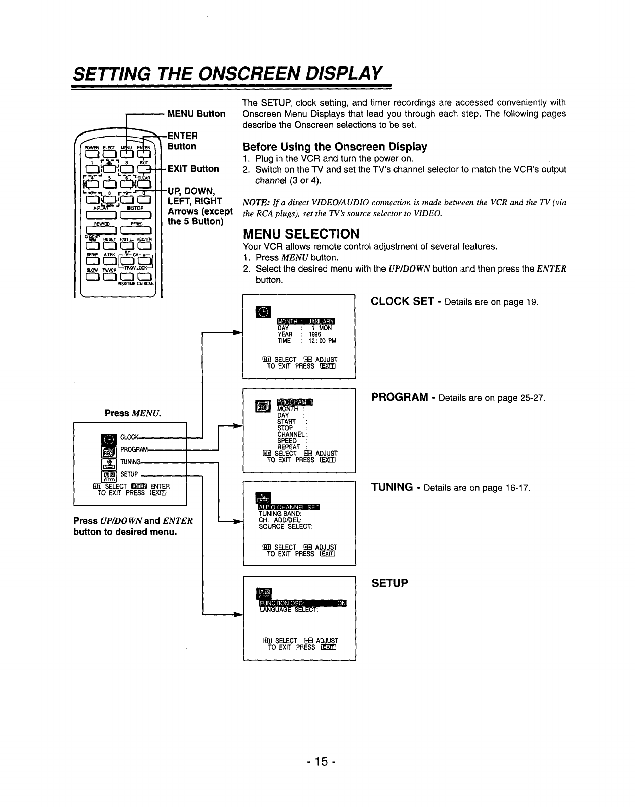
The SETUP, clock setting, and timer recordings are accessed conveniently with
Onscreen Menu Displays that lead you through each step. The following pages
describe the Onscreen selections to be set.
Before Using the Onscreen Display
1. Plug in the VCR and turn the power on.
2. Switch on the TV and set the TV's channel selector to match the VCR's output
channel (3 or 4).
NOTE: If a direct VIDEO/AUDIO connection is made between the VCR and the TV (via
the RCA plugs), set the TV's source selector to VIDEO.
MENU SELECTION
Your VCR allows remote control adjustment of several features.
1. Press MENU button.
2. Select the desired menu with the UP/DOWN button and then press the ENTER
button.
I
DAY 1MON
YEAR 1996
TIME 12 : 00 PM
_1_ SELECT _1_ ADJUST
TO EXIT PRESS
CLOCK SET -Details are on page 19.
MONTH :
DAY :
START :
STOP :
CHANNEL:
SPEED :
REPEAT :
[_]i] SELECT _ ADJUST
TO EXIT PRESS rk'XTlq
TUNING BAND:
CH. ADD/DEL:
SOURCE SELECT:
[{fi] SELECT _ ADJUST
TO EXIT PRESS
PROGRAM -Details are on page 25-27.
TUNING - Details are on page 16-17.
II
liU]_{#=tol_-;-
LANGUAGE SELECT:
[g_] SELECT [3B ADJUST
TO EXIT PRESS
SETUP
-15-
CHANNEL SELECTION
CLOCK
PROGRAM
1UNING
SETUP
_]m SELECT _ ENTER
TO EXIT PRESS [1_
TUNING BAND:
OH. ADD/DE'L:
SOURCE SELECT:
SELECT _ADJUST
TO EXIT PRESS IZ-k-ff3
[]
AUTO CHANNEL SET
TUNING BAND:
CH. ADD/DEL: m
_] SELECT _ADJUST
TO EXIT PRESS
TUNING BAND:
OH. ADD/DEL:
SOURCE SELECT:
B]_ SELECT _13 ADJUST
TO EXIT PRESS (_]3
AUTO CHANNEL SET
PROCEEDING
CHANNEL 2
TO EXIT PRESS
[]
_TO C_HA_N_I_IELSET
OH. ADD/DEL:
SOURCE SELECT:
_!_ SELECT E]_ ADJUST
TO EXIT PRESS
[]
AUTO CHANNEL SET
SOURCE SELECT:
ADO/DELETE
[]]_ SELECT HE]ADJUST
TO EXIT PRESS
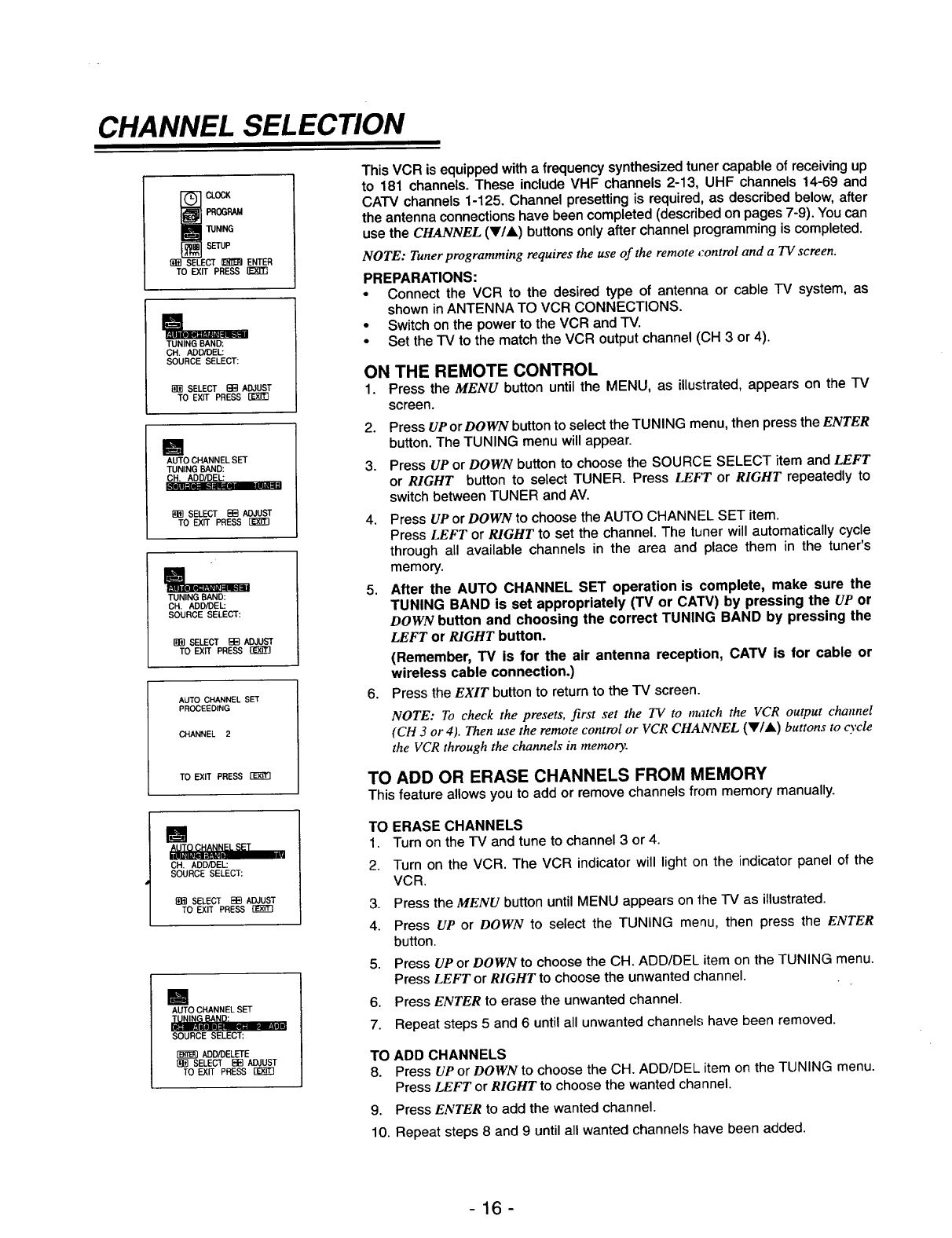
This VCR is equipped with a frequency synthesized tuner capable of receiving up
to 181 channels. These include VHF channels 2-13, UHF channels 14-69 and
CATV channels 1-125. Channel presetting is required, as described below, after
the antenna connections have been completed (described on pages 7-9). You can
use the CHANNEL (VIA) buttons only after channel programming is completed.
NOTE: Tuner programming requires the use of the remote control and a TV screen.
PREPARATIONS:
•Connect the VCR to the desired type of antenna or cable "IV system, as
shown inANTENNA TO VCR CONNECTIONS.
•Switch on the power to the VCR and -IV.
•Set the TV to the match the VCR output channel (CH 3 or 4).
ON THE REMOTE CONTROL
1. Press the MENU button until the MENU, as illustrated, appears on the IV
screen.
2. Press UP or DOWN button to select the TUNING menu, then press the ENTER
button. The TUNING menu will appear.
3. Press UP or DOWN button to choose the SOURCE SELECT item and LEFT
or RIGHT button to select TUNER. Press LEFT or RIGHT repeatedly to
switch between TUNER and AV.
4. Press UP or DOWN to choose the AUTO CHANNEL SET item.
Press LEFT or RIGHT to set the channel. The tuner will automatically cycle
through all available channels in the area and place them in the tuner's
memory.
5. After the AUTO CHANNEL SET operation is complete, make sure the
TUNING BAND is set appropriately (TM or CATV) by pressing the UP or
DOWN button and choosing the correct TUNING BAND by pressing the
LEFT or RIGHT button.
6°
(Remember, TV is for the air antenna reception, CATV is for cable or
wireless cable connection.)
Press the EXIT button to return to the TV screen.
NOTE: To check the presets, first set the TV to tr_tch the VCR output channel
(CH 3 or 4). Then use the remote control or VCR CHANNEL (Y/&) buttons to cycle
the VCR through the channels in memory.
TO ADD OR ERASE CHANNELS FROM MEMORY
This feature allows you to add or remove channels from memory manually.
TO ERASE CHANNELS
1. Turn on the FV and tune to channel 3 or 4.
2. Turn on the VCR. The VCR indicator will light on the indicator panel of the
VCR.
3. Press the MENU button until MENU appears on the TV as illustrated.
4. Press UP or DOWN to select the TUNING menu, then press the ENTER
button.
5. Press UP or DOWN to choose the CH. ADD/DEL item on the TUNING menu.
Press LEFT or RIGHT to choose the unwanted channel.
6. Press ENTER to erase the unwanted channel.
7. Repeat steps 5 and 6 until all unwanted channels have been removed.
TO ADD CHANNELS
8. Press UP or DOWN to choose the CH. ADD/DEL item on the TUNING menu.
Press LEFT or RIGHT to choose the wanted channel.
9. Press ENTER to add the wanted channel.
10. Repeat steps 8 and 9 until all wanted channels have been added.
-16-
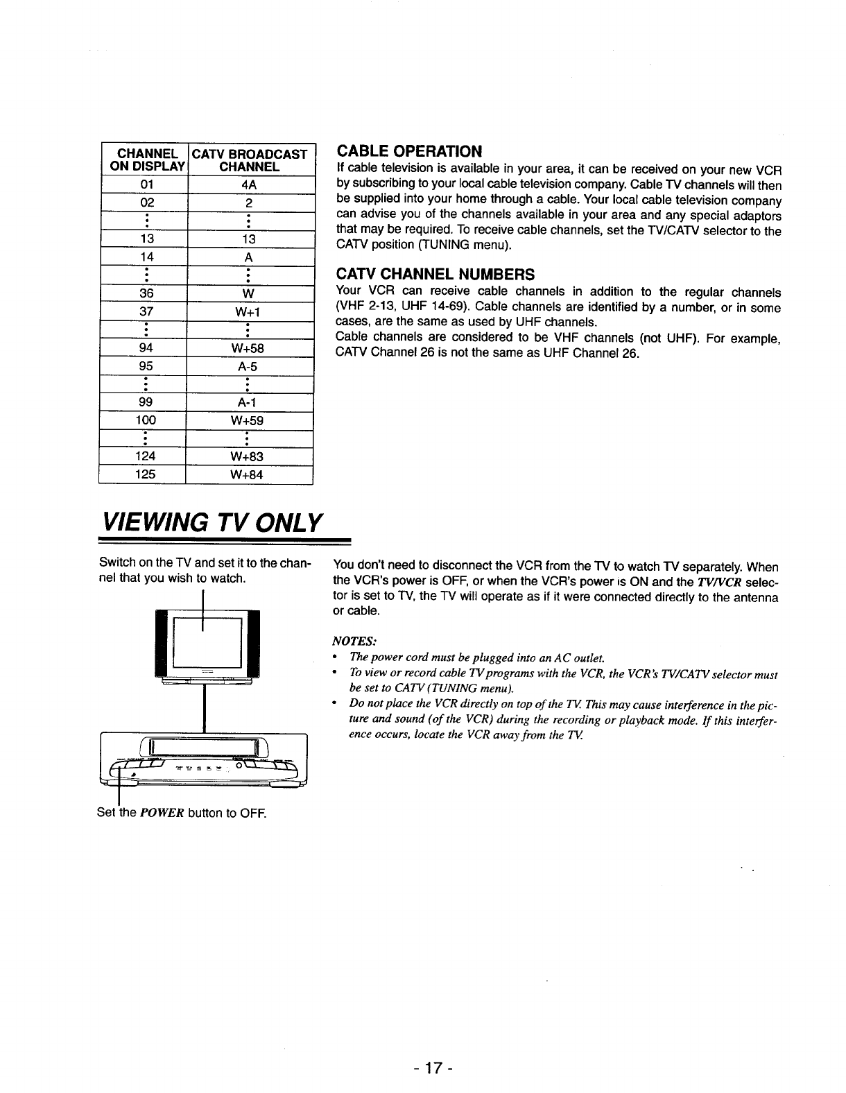
CHANNEL
ON DISPLAY
01
02
13
14
36
37
94
95
99
100
124
125
CATV BROADCAST
CHANNEL
4A
2
13
A
W
W+I
W+58
A-5
A-1
W+59
W+83
W+84
CABLE OPERATION
If cable television is available in your area, it can be received on your new VCR
by subscribing to your local cable television company. Cable "IV channels will then
be supplied into your home through a cable. Your local cable television company
can advise you of the channels available in your area and any special adaptors
that may be required. To receive cable channels, set the W/CAW selector to the
CATV position (TUNING menu).
CATV CHANNEL NUMBERS
Your VCR can receive cable channels in addition to the regular channels
(VHF 2-13, UHF 14-69). Cable channels are identified by a number, or in some
cases, are the same as used by UHF channels.
Cable channels are considered to be VHF channels (not UHF). For example,
CATV Channel 26 is not the same as UHF Channel 26.
VIEWING TV ONLY
Switch on the -iV and set it to the chan-
nel that you wish to watch.
Set the POWER button to OFE
You don't need to disconnect the VCR from the TV to watch "IV separately. When
the VCR's power is OFF, or when the VCR's power is ON and the TV/VCR selec-
tor is set to TV, the IV will operate as if it were connected directly to the antenna
or cable.
NOTES:
•The power cord must be plugged into an A C outlet.
•To view or record cable 73/programs with the VCR, the VCR's TV/CATV selector must
be set to CATV (TUNING menu).
•D°n°tplacetheVCRdirectly°nt°p°ftheTV'Thismaycauseinterferenceinthepic-
ture and sound (of the VCR) during the recording or playback mode. If this interfer-
ence occurs, locate the VCR away from the TV
-17-
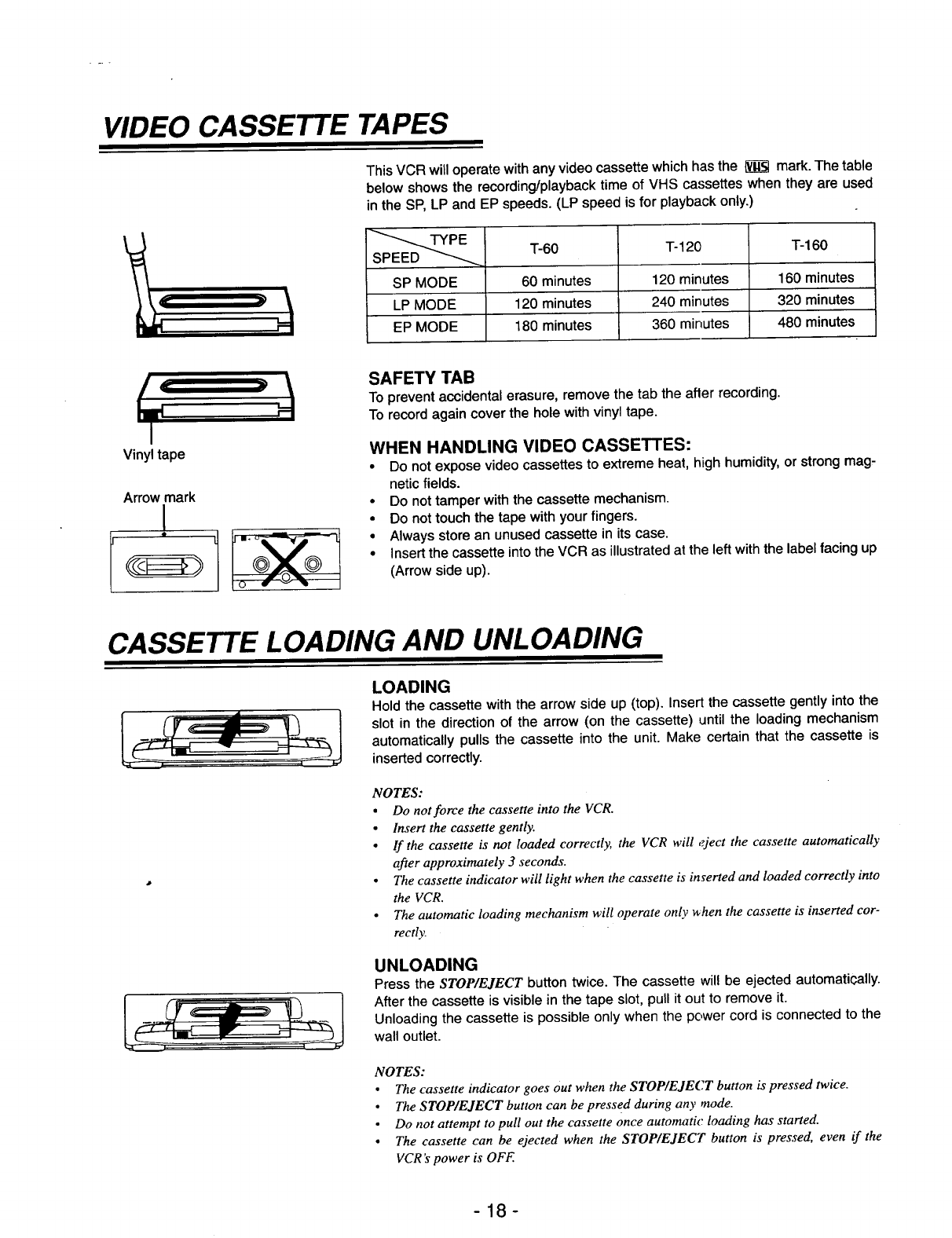
VIDEO CASSETTE TAPES
This VCR will operate with any video cassette which has the l_ mark. The table
below shows the recording/playback time of VHS cassettes when they are used
in the SP, LP and EP speeds. (LP speed is for playback only.)
T-60 T- 120 T-160
i
SP MODE 60 minutes 120 minutes 160 minutes
LP MODE 120 minutes 240 minutes 320 minutes
EP MODE 180 minutes 360 minutes 480 minutes
I
Vinyl tape
Arrow mark
I
SAFETY TAB
To prevent accidental erasure, remove the tab the after recording.
To record again cover the hole with vinyl tape.
WHEN HANDLING VIDEO CASSETTES:
•Do not expose video cassettes to extreme heat, high humidity, or strong mag-
netic fields.
• Do not tamper with the cassette mechanism.
•Do not touch the tape with your fingers.
• Always store an unused cassette in its case.
• Insert the cassette into the VCR as illustrated at the left with the label facing up
(Arrow side up).
CASSETTE LOADING AND UNLOADING
LOADING
Hold the cassette with the arrow side up (top). Insert the cassette gently into the
slot in the direction of the arrow (on the cassette) until the loading mechanism
automatically pulls the cassette into the unit. Make certain that the cassette is
inserted correctly.
NOTES:
•Do not force the cassette into the VCR.
•Insert the cassette gently.
• If the cassette is not loaded correctly, the VCR will eject the cassette automatically
after approximately 3 seconds.
•The cassette indicator will light when the cassette is inserted and loaded correctly into
the VCR,
•The automatic loading mechanism will operate only _hen the cassette is inserted cor-
rectl):
UNLOADING
Press the STOP/EJECT button twice. The cassette will be ejected automatically.
After the cassette is visible in the tape slot, pull it out to remove it.
Unloading the cassette is possible only when the power cord is connected to the
wall outlet.
NOTES:
•The cassette indicator goes out when the STOP/EJECT button is pressed twice.
• The STOP/EJECT button can be pressed during any mode.
• Do not attempt to pull out the cassette once automatic loading has started.
• The cassette can be ejected when the STOP/EJECT button is pressed, even if the
VCR's power is OFF.
-18-
SETTING THE CLOCK
POWER EJECT MENU ENTER
b'pLI_P "_ J ISTOP
REW/_ FF/_}
c-----! r-----i
MENU Button
-UP, DOWN,
LEFT, RIGHT
Arrows (except
the 5 Button)
MAIN MENU
_ LOCK
PROGRAM
TUNING
SETUP
(!fi] SELECT _ ENTER
TO EXIT PRESS
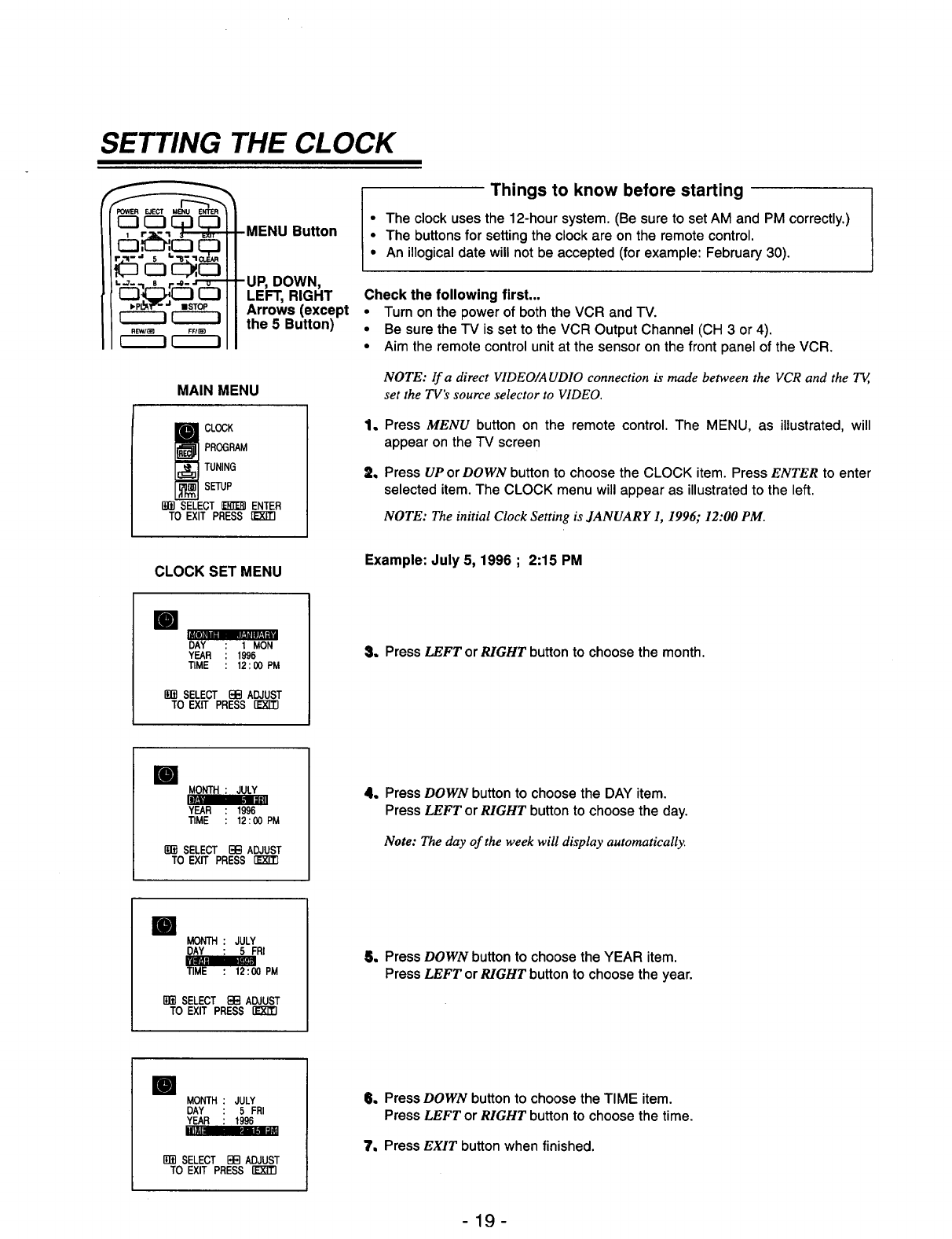
Things to know before starting
• The clock uses the 12-hour system. (Be sure to set AM and PM correctly.)
•The buttons for setting the clock are on the remote control.
•An illogical date will not be accepted (for example: February 30).
Check the following first,..
•Turnon the powerof boththe VCR and IV.
•Be surethe TV is setto the VCR OutputChannel (CH 3 or4).
•Aim the remotecontrolunitat the sensoron the front panel of the VCR.
NOTE: If a direct VIDEO/AUDIO connection is made between the VCR and the T_,
set the TV's source selector to VIDEO.
Q
q
Press MENU button on the remote control. The MENU, as illustrated, will
appear on the TV screen
Press UP or DOWN button to choose the CLOCK item. Press ENTER to enter
selected item. The CLOCK menu will appear as illustrated to the left.
NOTE: The initial Clock Setting is JANUARY 1, 1996; 12:00 PM.
CLOCK SET MENU Example: July 5, 1996 ; 2:15 PM
lm mimmlW_
DAY 1MON
YEAR 1996
TIME 12 : 00 PM
liffl SELECT B[_]ADJUST
TO EXIT PRESS [E'X'T'rl
S. Press LEFT or RIGHT button to choose the month.
ml
YEAR : 1996
TIME : 12:00PM
1_ SELECT BB ADJUST
TO EXIT PRESS
4. Press DOWN button to choose the DAY item.
Press LEFT or RIGHT button to choose the day.
Note: The day of the week will display automatically.
ml MONTH : JULY
DAY : 5 FRI
_00 PM
Ig_ SELECT F:I:;:IADJUST
TO EXIT PRESS
5, Press DOWN button to choose the YEAR item.
Press LEFT or RIGHT button to choose the year.
ml MONTH JULY
DAY 5 FRI
YEAR 1996
im= _m_lr_
SELECT EEl ADJUST
TO EXIT PRESS [_
II, Press DOWN button to choose the TIME item.
Press LEFT or RIGHT button to choose the time.
"t, Press EXIT button when finished.
-19-
NORMAL PLAYBACK
POWER EJECT MENU ENTER
J
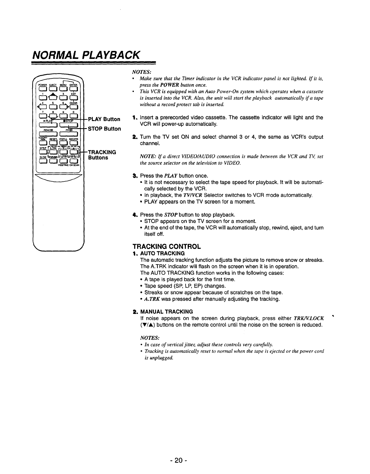
PLAY Button
-STOP Button
Bu_ons
NOTES:
•Make sure that the Timer indicator in the VCR indicator panel is not lighted. If it is,
press the POWER button once.
•This VCR is equipped with an Auto Power-On system which operates when a cassette
is inserted into the VCR. Also, the unit will start the playback automatically if a tape
without a record protect tab is inserted.
_m
2,
Insert aprerecorded video cassette. The cassette indicator will light and the
VCR will power-up automatically.
Turn the TV set ON and select channel 3 or 4, the same as VCR's output
channel.
NOTE: lf a direct VIDEO/AUDIO connection is made between the VCR and T_, set
the source selector on the television to VIDEO.
_w Press the PLAY button once.
•It is not necessary to select the tape speed for playback. It will be automati-
cally selected by the VCR.
•In playback, the TV/VCR Selector switches to VCR mode automatically.
•PLAY appears on the TV screen for a moment.
1Press the STOP button to stop playback.
•STOP appears on the TV screen for a moment.
•At the end of the tape, the VCR will automatically stop, rewind, eject, and turn
itself off.
TRACKING CONTROL
1. AUTO TRACKING
The automatic tracking function adjusts the picture to remove snow or streaks.
The A.TRK indicator will flash on the screen when it is in operation.
The AUTO TRACKING function works in the following cases:
• A tape is played back for the first time.
• Tape speed (SP, LP, EP) changes.
• Streaks or snow appear because of scratches on the tape.
•A.TRK was pressed after manually adjusting the tracking.
2. MANUAL TRACKING
If noise appears on the screen during playback, press either TRK/ELOCK
(V/A) buttons on the remote control until the noise on the screen is reduced.
NOTES:
• In case of vertical jitter, adjust these controls very carefully.
•Tracking is automatically reset to normal when the tape i_"ejected or the power cord
is unplugged.
- 20 -
SPECIAL EFFECTS PLAYBACK
POWER EJECT MEt_ ENTER
cb c3
IISTOP
PPIL_
PLAY Button
REW Button
-FF Button
P/STiLL
Button
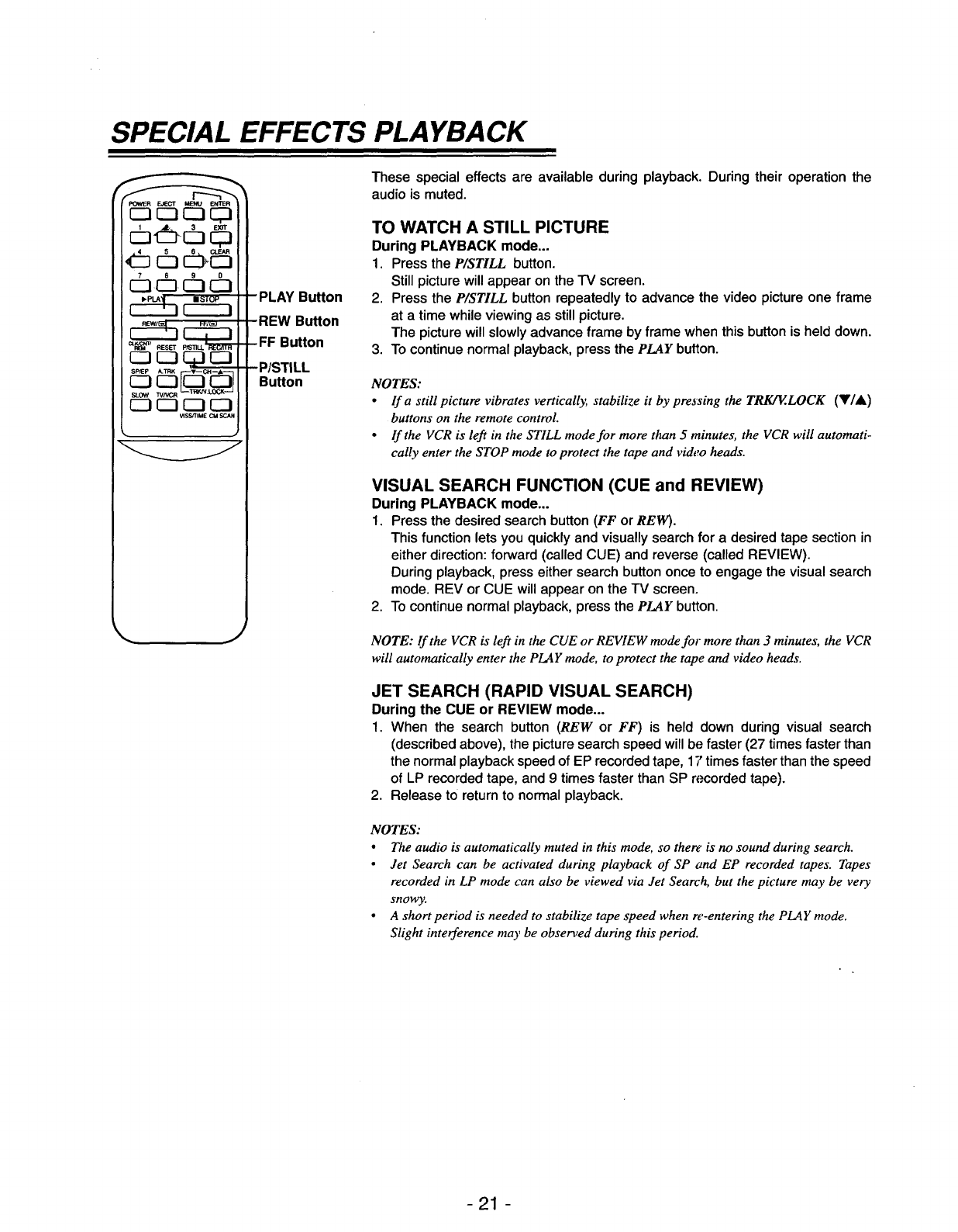
These special effects are available during playback. During their operation the
audio is muted.
TO WATCH A STILL PICTURE
During PLAYBACK mode,..
1. Press the P/STILL button.
Still picture will appear on the TV screen.
2. Press the P/STILL button repeatedly to advance the video picture one frame
at a time while viewing as still picture.
The picture will slowly advance frame by frame when this button is held down.
3. To continue normal playback, press the PLAY button.
NOTES:
•lf a still picture vibrates vertically, stabilize it by pressing the TRKJE.LOCK (VI&)
buttons on the remote control.
• If the VCR is left in the STILL mode for more than 5minutes, the VCR will automati-
cally enter the STOP mode to protect the tape and video heads.
VISUAL SEARCH FUNCTION (CUE and REVIEW)
During PLAYBACK mode.,.
1. Press the desired search button (FF or RELY).
This function lets you quickly and visually search for a desired tape section in
either direction: forward (called CUE) and reverse (called REVIEW).
During playback, press either search button once to engage the visual search
mode. REV or CUE will appear on the TV screen.
2. To continue normal playback, press the PLAY button.
NOTE: If the VCR is left in the CUE or REVIEW mode for more than 3 minutes, the VCR
will automatically enter the PLAY mode, to protect the tape and video heads.
JET SEARCH (RAPID VISUAL SEARCH)
During the CUE or REVIEW mode...
1. When the search button (REW or FF) is held down during visual search
(described above), the picture search speed will be faster (27 times faster than
the normal playback speed of EP recorded tape, 17 times faster than the speed
of LP recorded tape, and 9 times faster than SP recorded tape).
2. Release to return to normal playback.
NOTES:
•The audio is automatically muted in this mode, so there is no sound during search.
• Jet Search can be activated during playback of SP and EP recorded tapes. Tapes
recorded in LP mode can also be viewed via Jet Search, but the picture may be very
snowy.
• A short period is needed to stabilize tape speed when re-entering the PLAY mode.
Slight interference may be observed during this period.
-21 -
_OWER EJECT MENU ENTI_R
tl_J RESET
_3 _ r--I IZI
PLAY Bu_on
REWBu_on
-FF Bu_on
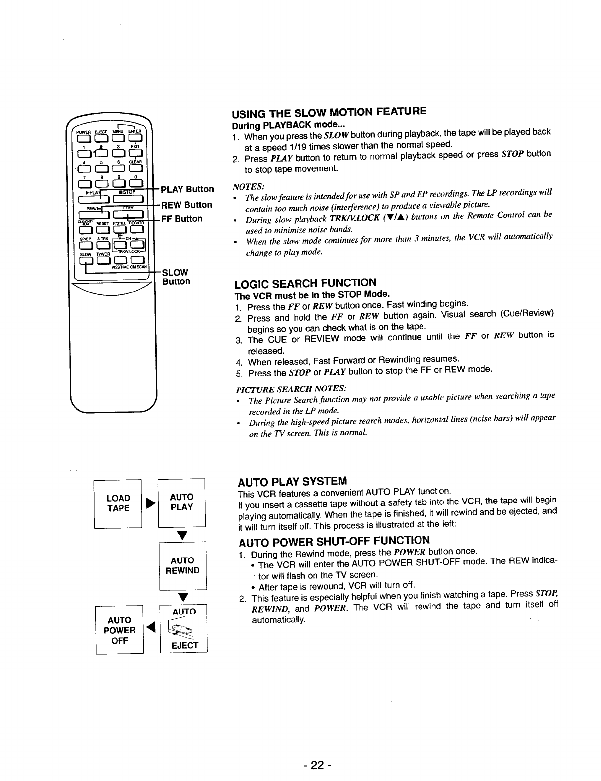
SLOW
Button
USING THE SLOW MOTION FEATURE
During PLAYBACK mode...
1. When you press the SLOW button during playback, the tape will be played back
at a speed 1/19 times slower than the normal speed.
2. Press PLAY button to return to normal playback speed or press STOP button
to stop tape movement.
NOTES:
•The slow feature is intended for use with SP and EP reo_rdings. The LP recordings will
contain too much noise (interference) to produce a viewable picture.
•During slow playback TRKIV.LOCK (Y/&) buttons on the Remote Control can be
used to minimize noise bands.
• When the slow mode continues for more than 3 minutes, the VCR will automatically
change to play mode.
LOGIC SEARCH FUNCTION
The VCR must be in the STOP Mode.
1. Press the FF or REW button once. Fast winding begins.
2. Press and hold the FF or REW button again. Visual search (Cue/Review)
begins so you can check what is on the tape.
3. The CUE or REVIEW mode will continue until the FF or REW button is
released.
4. When released, Fast Forward or Rewinding resumes.
5. Press the STOP or PLAY button to stop the FF or REW mode.
PICTURE SEARCH NOTES:
• The Picture Search function may not provide a usable picture when searching a tape
recorded in the LP mode.
• During the high-speed picture search modes, horizontal lines (noise bars) will appear
on the TV screen. This is normal
LOAD _ll_[
TAPE
AUTO ],_
POWER
OFF
AUTO
PLAY
AUTO
REWIND
AUTO
EJECT
AUTO PLAY SYSTEM
This VCR features a convenient AUTO PLAY function.
If you insert a cassette tape without a safety tab into the VCR, the tape will begin
playing automatically. When the tape is finished, it will rewind and be ejected, and
it will turn itself off. This process is illustrated at the left:
AUTO POWER SHUT-OFF FUNCTION
1. During the Rewind mode, press the POWER button once.
•The VCR will enter the AUTO POWER SHUT-OFF mode. The REW indica-
• tor will flash on the TV screen.
•After tape is rewound, VCR will turn off.
2. This feature is especially helpful when you finish watching a tape. Press STOP,
REWIND, and POWER. The VCR will rewind the tape and turn itself off
automatically.
- 22 -
VISS (VHS Index Search System)/TIME SEARCH
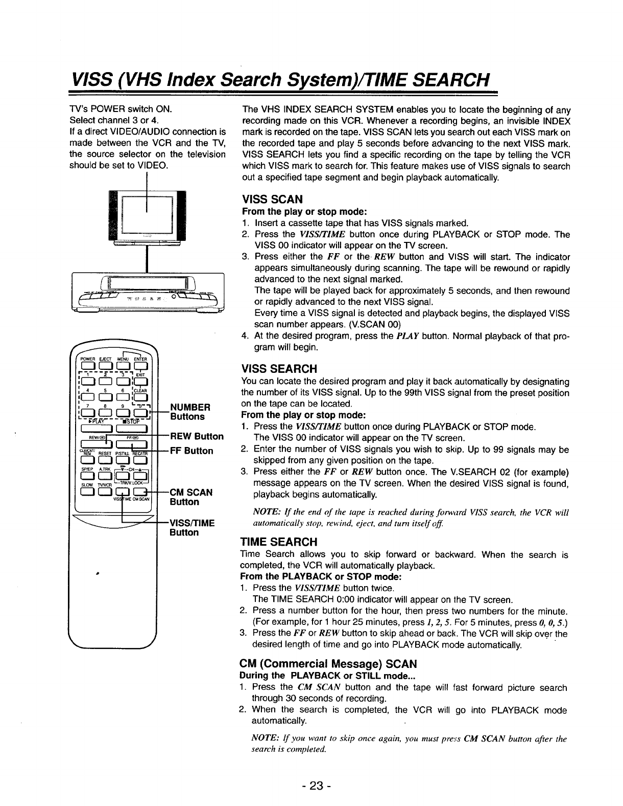
TV's POWER switch ON.
Select channel 3 or 4.
If a direct VIDEO/AUDIO connection is
made between the VCR and the TV,
the source selector on the television
should be set to VIDEO.
I
J
POWER EJECT MENU ENTER
"[_= - 3 "I EXT
7 8 9 L_-'I
•-__ ---="s1"ol5-
1IL..__.._I
CL_NT/ RESET
SLOW WNCR TRKN LOCK
NUMBER
Buttons
REW Button
•.• FF Button
mCM SCAN
Button
VISS/TIME
Button
j
The VHS INDEX SEARCH SYSTEM enables you to locate the beginning of any
recording made on this VCR. Whenever a recording begins, an invisible INDEX
mark is recorded on the tape. VlSS SCAN lets you search out each VlSS mark on
the recorded tape and play 5 seconds before advancing to the next VISS mark.
VlSS SEARCH lets you find a specific recording on the tape by telling the VCR
which VlSS mark to search for. This feature makes use of VISS signals to search
out a specified tape segment and begin playback automatically.
VISS SCAN
From the play or stop mode:
1. Insert a cassette tape that has VISS signals marked.
2. Press the FIEE/TIME button once during PLAYBACK or STOP mode. The
VISS 00 indicator will appear on the TV screen.
3. Press either the FF or the REW button and VISS will start. The indicator
appears simultaneously during scanning. The tape will be rewound or rapidly
advanced to the next signal marked.
The tape will be played back for approximately 5 seconds, and then rewound
or rapidly advanced to the next VISS signal.
Every time aVISS signal is detected and playback begins, the displayed VISS
scan number appears. (V.SCAN 00)
4. At the desired program, press the PLAY button. Normal playback of that pro-
gram will begin.
VISS SEARCH
You can locate the desired program and play it back automatically by designating
the number of its VISS signal. Up to the 99th VISS signal from the preset position
on the tape can be located.
From the play or stop mode:
1. Press the VISS/TIME button once during PLAYBACK or STOP mode.
The VISS 00 indicator will appear on the "IV screen.
2. Enter the number of VISS signals you wish to skip. Up to 99 signals may be
skipped from any given position on the tape.
3. Press either the FF or REW button once. The V.SEARCH 02 (for example)
message appears on the TV screen. When the desired VISS signal is found,
playback begins automatically.
NOTE: If the end of the tape is reached during forward VISS search, the VCR will
automatically stop, rewind, eject, and turn itself off.
TIME SEARCH
Time Search allows you to skip forward or backward. When the search is
completed, the VCR will automatically playback.
From the PLAYBACK or STOP mode:
1. Press the VISS/TIME button twice.
The TIME SEARCH 0:00 indicator will appear on the TV screen.
2. Press a number button for the hour, then press two numbers for the minute.
(For example, for 1 hour 25 minutes, press 1, 2, 5. For 5 minutes, press 0, 0, 5.)
3. Press the FF or REW button to skip ahead or back. The VCR will skip ov.er the
desired length of time and go into PLAYBACK mode automatically.
CM (Commercial Message) SCAN
During the PLAYBACK or STILL mode...
1. Press the CM SCAN button and the tape will fast forward picture search
through 30 seconds of recording.
2. When the search is completed, the VCR will go into PLAYBACK mode
automatically.
NOTE: lf you want to skip once again, you must press CM SCAN button after the
search is completed.
-23 -
NORMAL RECORDING
PREPARATIONS:
•Make sure that the Timer indicator
is OFF. If the Timer indicator
appears, press the POWER button
once. The indicator should go off. If
the power indicator is not shown,
press the POWER button again.
•Be sure that the safety tab is in
place. If it is missing, the VCR will
enter the AUTO PLAY mode when
the tape is inserted.
The full auto play function will start.
Insert a cassette with tab in place,
or cover the hole with a piece of cel-
lophane tape.
d]" did]
I_PI_A__: ==STOP
r-----I CZ_3-
IEWI(_ FF/eE]
_I_(_M /RESET p/STILL RECtrFR
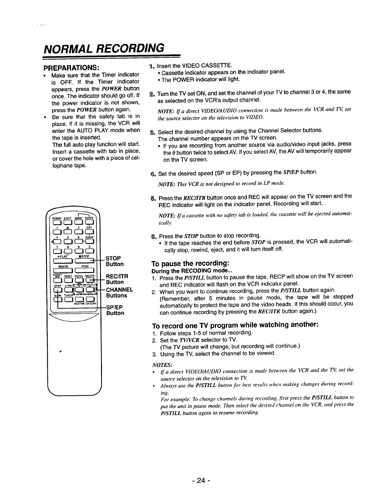
.STOP
Button
REC/ITR
•Button
Buttons
Button
J
_1, Insert the VIDEO CASSE'i-I-E.
• Cassette indicator appears on the indicator panel.
• The POWER indicator will light.
_Q Turn the TV set ON, and set the channel of your TV to channel 3or 4, the same
as selected on the VCR's output channel.
NOTE: Ira direct VIDEO/AUDIO connection is made between the VCR and T_, set
the source selector on the television to VIDEO.
_a Select the desired channel by using the Channel Selector buttons.
The channel number appears on the TV screen.
•If you are recording from another source via audio/video input jacks, press
the 0button twice to select AV. If you select AV, the AV will temporarily appear
on the TV screen.
#,, Set the desired speed (SP or EP) by pressing the SP/EP button.
NOTE: This VCR is not designed to record in LP mode.
Press the REC/ITR button once and REC will appear on the TV screen and the
REC indicator will light on the indicator panel. Recording will start.
NOTE: lf a cassette with no safety tab is loaded, the cassette will be ejected automat-
ically.
_= Press the STOP button to stop recording.
•If the tape reaches the end before STOP is pressed, the VCR will automati-
cally stop, rewind, eject, and it will turn itself off.
To pause the recording:
During the RECODING mode...
1. Press the P/STILL buttonto pause the tape. RECP will show on the TV screen
and REC indicator will flash on the VCR indicator panel.
2. When you want to continue recording, press the P/STILL button again.
(Remember, after 5 minutes in pause mode, the tape will be stopped
automatically to protect the tape and the video heads. If this should occur, you
can continue recording by pressing the REC/ITR button again.)
To record one TV program while watching another:
1. Follow steps 1-5 of normal recording,
2. Set the 73.'/FCR selector to -IV.
(The TV picture will change, but recording will continue.)
3. Using the TV, select the channel to be viewed.
NOTES:
•lfa direct VIDEO/AUDIO connection is made between the VCR and the TE, set the
source selector on the television to TV.
•Always use the P/STILL button for best results when making changes during record-
ing.
For example: To change channels during recording, first press the P/STILL button to
put the unit in pause mode. Then select the desired channel on the VCR, and press the
P/STILL button again to resume recording.
-24 -
TIMER RECORDING
C_::I CSS:I
REWlB_J FFt_
r---i f_--i
RI_J_ _1 RESL_T p/S13LL REC/TTR
SLOW WNCR TRKN.LOCK
Button
DOWN,
LEFT, RIGHT
Arrows (except
the 5 Button)
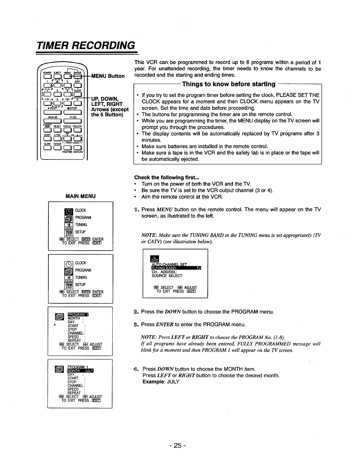
This VCR can be programmed to record up to 8programs within a period of 1
year. For unattended recording, the timer needs to know the channels to be
recorded and the starting and ending times.
Things to know before starting
•If you try to set the program timer before setting the clock, PLEASE SET THE
CLOCK appears for a moment and then CLOCK menu appears on the IV
screen. Set the time and date before proceeding,
•The buttons for programming the timer are on the remote control.
•While you are programming the timer, the MENU display on therV screen will
prompt you through the procedures.
•The display contents will be automatically replaced by IV programs after 3
minutes.
•Make sure batteries are installed in the remote control.
•Make sure atape is in the VCR and the safety tab is in place or the tape will
be automatically ejected.
MAIN MENU
CLOCK
_ROGRAM
TUNING
SETUP
[B_ SELECT _ ENTER
TO EXIT PRESS
Check the following first...
•Turn on the power of both the VCR and the "IV.
•Be sure the "IV is set to the VCR output channel (3 or 4).
•Aim the remote control at the VCR.
_]o Press MENU button on the remote control. The menu will appear on the IV
screen, as illustrated to the left.
NOTE: Make sure the TUNING BAND in the TUNING menu is set appropriately (TV
or CATV) (see illustration below).
-_ CLOCK
_ ROGRAM
TUNING
SETUP
SELECT E_ ENTER
TO EXIT PRESS []_
B
AUTO CHANNEL SET
CH. ADO/DEL:
SOURCE SELECT:
SELECT EEl ADJUST
TO EXIT PRESS
MONTH :
DAY :
•START :
STOP :
CHANNEL:
SPEED :
REPEAT
SELECT I_ ADJUST
TO EXIT PRESS
_o Press the DOWN button to choose the PROGRAM menu.
_o Press ENTER to enter the PROGRAM menu.
NOTE: Press LEFT or RIGHT to choose the PROGRAM No. (1-8).
If all programs have already been entered, FULLY PROGRAMMED message will
blink for a moment and then PROGRAM 1 will appear on the TV screen.
,_ PROGRAM 1
DAY
START :
STOP
CHANNELi
SPEED :
REPEAT :
SELECT {3E}ADJUST
TO EXIT PRESS flt_ETl
_o Press DOWN button to choose the MONTH item.
Press LEFT or RIGHT button to choose the desired month.
Example: JULY
- 25 -
--_ PROGRAM 1
START
STOP :
CHANNEL :
SPEED :
REPEAT :
[_] SELECT EI_ ADJUST
TO EXIT PRESS
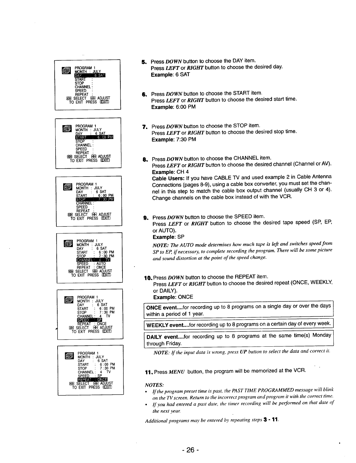
5. Press DOWN button to choose the DAY item.
Press LEFT or RIGHT button to choose the desired day.
Example: 6 SAT
6. Press DOWN button to choose the START item,
Press LEFT or RIGHT button to choose the desired start time.
Example: 6:00 PM
I_J PROGRAM 1
MONTH : JULY
STOP
CHANNEL
SPEED :
REPEAT :
SELECT _13 ADJUST
TO EXIT PRESS {E_3
WPROGRAM 1
MONTH : JULY
DAY :6SAT
START :6:00 PM
SPEED :
REPEAT :
SELECT _ ADJUST
TO EXIT PRESS
m PROGRAM 1
MONTH : JULY
DAY : 6 SAT
START : 6:00 PM
STOP : 7:30 PM
SPEED :AUTO
REPEAT :ONCE
{_]SELECT E_}ADJUST
TO EXIT PRESS {]_E!3
W ROGRAM 1
MONTH : JULY
DAY :6 SAT
START : 6:00PM
STOP :7:30PM
CHANNEL: 4 TV
REPEAT :ONCE
SELECT E_E]ADJUST
TO EXiT PRESS
r_ PROGRAMMONTH : JULY
DAY :6SAT
START : 6:00 PM
STOP : 7:30 PM
CHANNEL: 4 TV
SPEED : SP
E{_]S_UST
TO EXIT PRESS {]_g_
7, Press DOWN button to choose the STOP item.
Press LEFT or RIGHT button to choose the desired stop time.
Example: 7:30 PM
1Press DOWN button to choose the CHANNEL item.
Press LEFT or RIGHT button to choose the desired channel (Channel or AV).
Example: CH 4
Cable Users: If you have CABLE TV and used example 2 in Cable Antenna
Connections (pages 8-9), using a cable box converter, you must set the chan-
nel in this step to match the cable box output channel (usually CH 3 or 4).
Change channels on the cable box instead of with the VCR.
1Press DOWN button to choose the SPEED item.
Press LEFT or RIGHT button to choose the desired tape speed (SP, EP,
or AUTO).
Example: SP
NOTE: The AUTO mode determines how much tape is left and switches speed from
SP to EP, if necessary, to complete recording the program. There will be some picture
and sound distortion at the point of the speed change.
10. Press DOWN button to choose the REPEAT item.
Press LEFT or RIGHT button to choose the desired repeat (ONCE, WEEKLY,
or DAILY).
Example: ONCE
I ONCE event....for recording up to 8 programs on a single day or over the days I
within a period of 1 year.
WEEKLY recording up programs on a day every I
event....for to 8 certain of week.
IDALLY event'"'f°r rec°rding uP t° 8 pr°grams at the same time(s) M°nday[throughFriday.
NOTE: If the input data is wrong, press UP button to select the data and correct it.
11, Press MENU button, the program will be memorized at the VCR.
NOTES:
•If the program preset time is past, the PAST TIME PROGRAMMED message will blink
on the TV screen. Return to the incorrect program and program it with the correct time.
• If you had entered a past date, the timer recording will be performed on that date of
the next year.
Additional programs may be entered by repeating steps 3-11.
- 26 -
_LOCK
PROGRAM
TUNING
SETUP
SELECT _ENTER
TO EXIT PRESS
t_-]m MONTH : JULY
DAY :6SAT
START : 6:00 PM
STOP : 7:30 PM
CHANNEL: 4 rv
SPEED : AUTO
REPEAT : ONCE
TO ERASE PRESS_
TO EXIT PRESS
12. Press EXIT button when finished.
Cable Users: If your cable hookup is via a TV converter box, you can program
multiple recordings only on the converter box output channel. This is because the
converter determines what channel you view through your VCR.
NOTE: If you are finished programming and you want to set the VCR to record the pro-
grams you have entered.
A) MAKE SURE YOU HAVE INSERTED A TAPE INTO THE VCR.
B) YOU MUST TURN OFF THE VCR BEFORE IT _VILLRECORD ANY TIMER
PROGRAMS. (Timer indicator appears). The VCR is now set to record the preset pro-
grams.
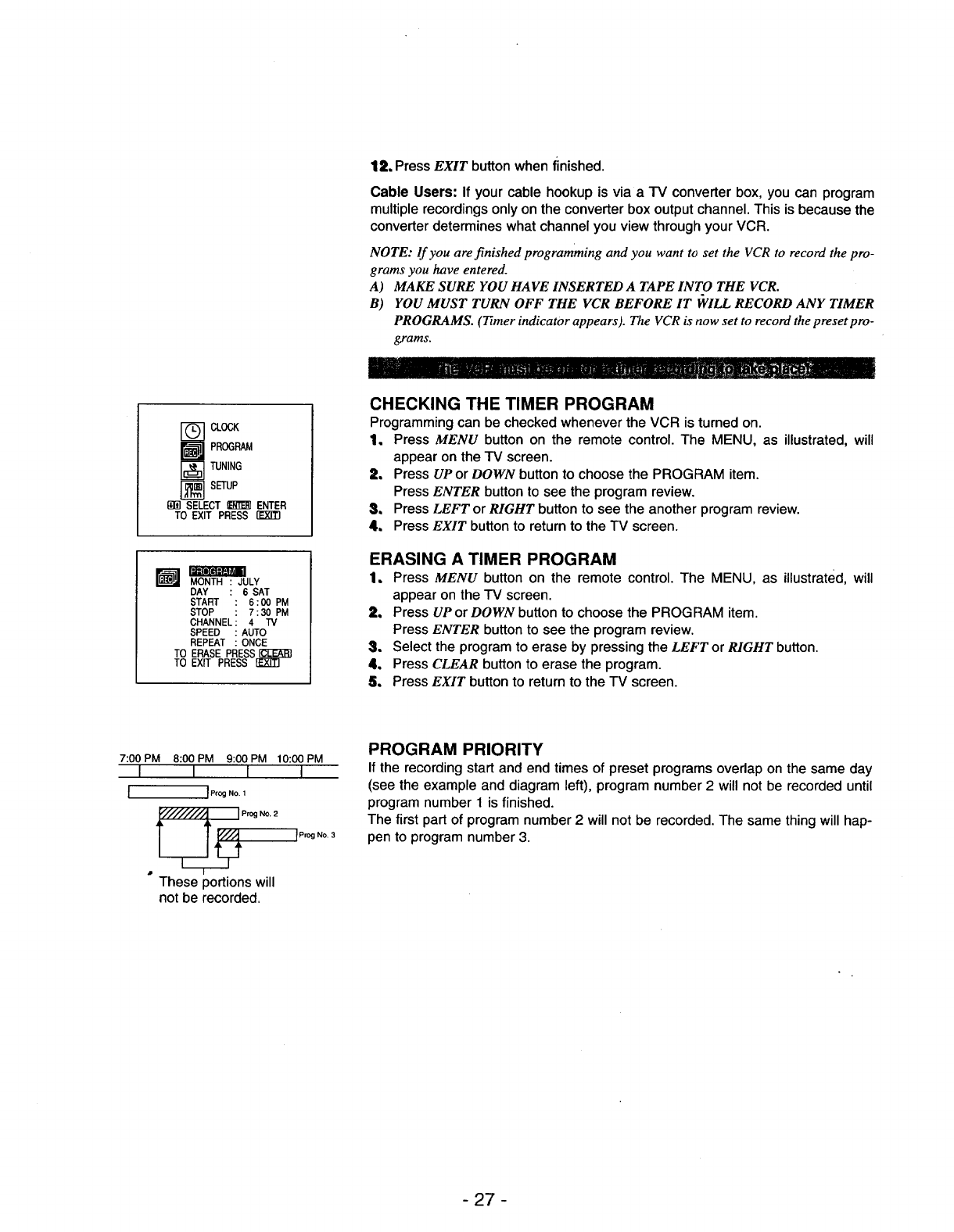
CHECKING THE TIMER PROGRAM
Programming can be checked whenever the VCR is turned on.
1. Press MENU button on the remote control. The MENU, as illustrated, will
appear on the TV screen.
2. Press UP or DOWN button to choose the PROGRAM item.
Press ENTER button to see the program review.
3. Press LEFT or RIGHT button to see the another program review.
4. Press EXIT button to return to the TV screen.
ERASING A TIMER PROGRAM
1. Press MENU button on the remote control. The MENU, as illustrated, will
appear on the TV screen.
2. Press UP or DOWN button to choose the PROGRAM item.
Press ENTER button to see the program review.
3. Select the program to erase by pressing the LEFT or RIGHT button.
4. Press CLEAR button to erase the program.
5° Press EXIT button to return to the TV screen.
7:00 PM 8:00 PM 9:00 PM 10:00 PM
I I I I
I p,o_.o,
_Prog NO. 2
IProg NO. 3
These portions will
not be recorded.
PROGRAM PRIORITY
If the recording start and end times of preset programs overlap on the same day
(see the example and diagram left), program number 2 will not be recorded until
program number 1 is finished.
The first part of program number 2 will not be recorded. The same thing will hap-
pen to program number 3.
- 27 -
INSTANT TIMER RECORDING (ITR)
POWER EJECT MENU ENTER
_3 _3 EZ3C;:3
6 cbcb
,PLA_" msToP
REWt_ FR(_
F----7 F---1
cLK_m RESET PtST_ RECJfTR REC/ITR
--Button
-CHANNEL
Buttons
SP/EP
Button
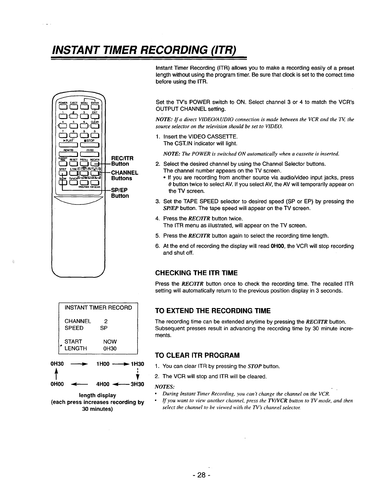
Instant "limer Recording (ITR) allows you to make a recording easily of a preset
length without using the program timer. Be sure that clock is set to the correct time
before using the ITR.
Set the TV's POWER switch to ON. Select channel 3 or 4 to match the VCR's
OUTPUT CHANNEL setting.
NOTE: lf a direct VIDEO/AUDIO connection is made between the VCR and the TE, the
source selector on the television should be set to VIDE().
1.
2.
Insert the VIDEO CASSETTE.
The CST, IN indicator will light.
NOTE: The POWER is switched ON automatically when a cassette is inserted.
Select the desired channel by using the Channel Selector buttons.
The channel number appears on the TV screen.
•If you are recording from another source via audio/video input jacks, press
0button twice to select AV. If you select AV, the AV will temporarily appear on
the TV screen.
3. Set the TAPE SPEED selector to desired speed (SP or EP) by pressing the
SP/EP button. The tape speed will appear on the TV screen.
4. Press the REC/ITR button twice.
The ITR menu as illustrated, will appear on the IV screen.
5. Press the REC/ITR button again to select the recording time length.
6. At the end of recording the display will read 0H00, the VCR will stop recording
and shut off.
JCHECKING THE ITR TIME
Press the REC/ITR button once to check the recording time. The recalled ITR
setting will automatically return to the previous position display in 3 seconds.
INSTANT TIMER RECORD
CHANNEL 2
SPEED SP
START NOW
*LENGTH 0H30
0H30 _1H00 _1H30
I
0H00 _4H00 _3H30
length display
(each press increases recording by
30 minutes)
TO EXTEND THE RECORDING TIME
The recording time can be extended anytime by pressing the REC/ITR button.
Subsequent presses result in advancing the recording time by 30 minute incre-
ments.
TO CLEAR ITR PROGRAM
1. You can clear ITR by pressing the STOP button.
2. The VCR will stop and ITR will be cleared.
NOTES:
•During Instant Timer Recording, you can't change the channel on the VCR.
•If you want to view another channel, press the TV/VCR button to TV mode, and then
select the channel to be viewed with the TV's chant, el selector.
- 28 -
TAPE COUNTER MEMORY FEATURE
F:'OWER EJECT MENU ENTER
_'P_ II STOP
RShT(_g FFI_
r----i r-----i
Q._NTI RESET p/STILL RECATR
V_StI"M_ CMSCAN
J
--ENTER
Button
RESET
Button
CLOCK/
COUNT/
REMAIN
Button
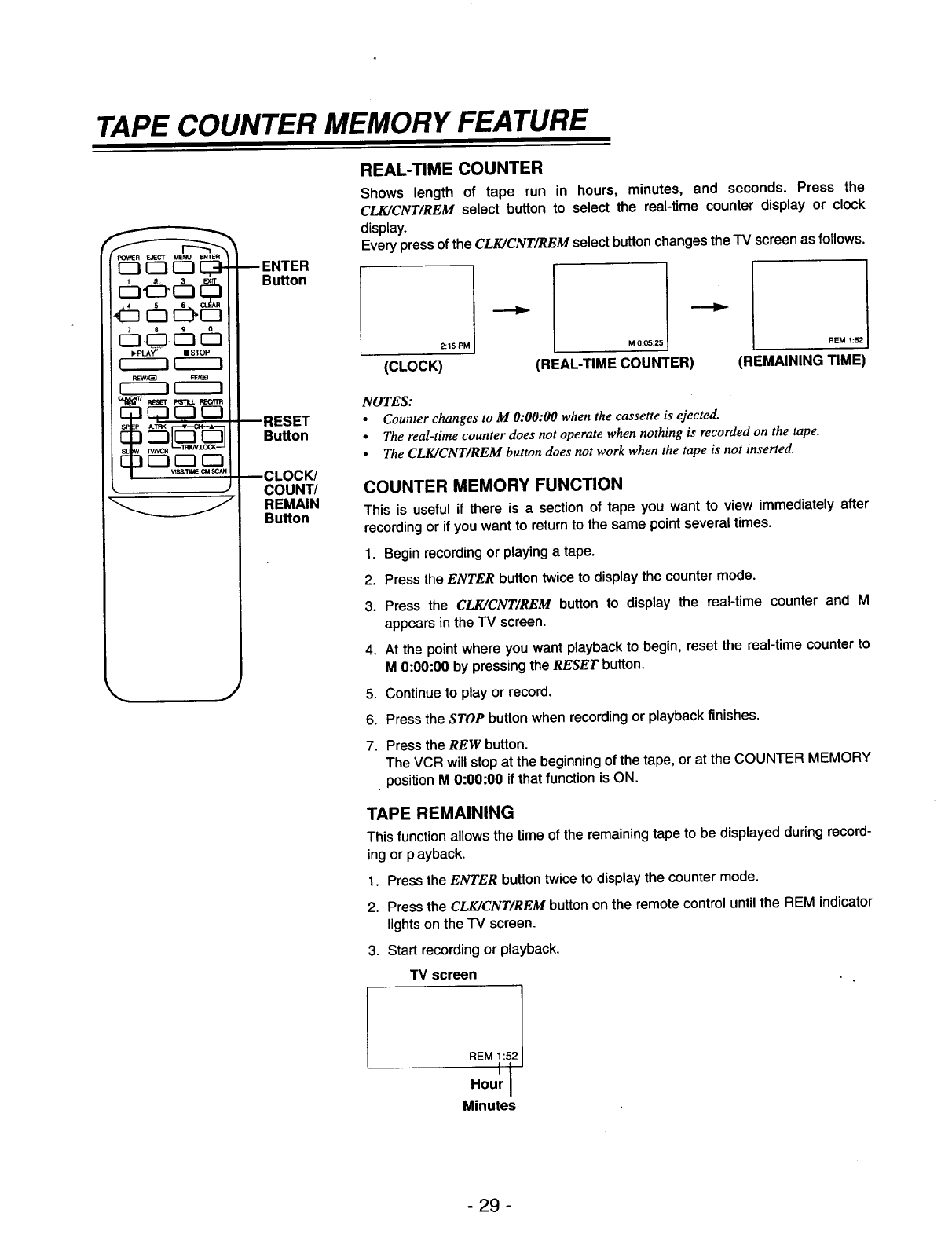
REAL-TIME COUNTER
Shows length of tape run in hours, minutes, and seconds. Press the
CLK/CNT/REM select button to select the real-time counter display or clock
display.
Every press of the CLK/CNT/REM select button changes the "IV screen as follows.
2:15 PM I
(CLOCK)
M 0:05:25 I
(REAL-TIME COUNTER)
REM 1:52 I
(REMAINING TIME)
NOTES:
•Counter changes to M 0:00:00 when the cassette is ejected.
•The real-time counter does not operate when nothing is recorded on the tape.
•The CLK/CNT/REM button does not work when the tape is not inserted.
COUNTER MEMORY FUNCTION
This is useful if there is a section of tape you want to view immediately after
recording or if you want to return to the same point several times.
1. Begin recording or playing a tape.
2. Press the ENTER button twice to display the counter mode.
3. Press the CLK/CNT/REM button to display the real-time counter and M
appears in the TV screen.
4. At the point where you want playback to begin, reset the real-time counter to
M0:00:00 by pressing the RESET button.
5. Continue to play or record.
6. Press the STOP button when recording or playback finishes.
7. Press the REW button.
The VCR will stop at the beginning of the tape, or at the COUNTER MEMORY
position M 0:00:00 if that function is ON.
TAPE REMAINING
This function allows the time of the remaining tape to be displayed during record-
ing or playback.
1. Press the ENTER button twice to display the counter mode.
2. Press the CLK/CNT/REM button on the remote control until the REM indicator
lights on the TV screen.
3. Start recording or playback.
TV screen
Minutes
-29 -
EDITING A RECORDING
1. Press the PLAY button and watch the program until you reach the exact point
where you want the new recording to start.
2. Press the P/STILL button.
3. Press the .P_C/ITR button once. The program material to be recorded will
appear on the television.
4. When you wish to start recording, press the P/STILL button again. The new
program material will directly follow the previously recorded material. This
feature is especially helpful during camcorder-to-VCR dubbing use so each
segment of the recording becomes a continuous program.
AUTO REWIND
In manual recording, "13merrecording, Instant Timer Recording, playbacK, or _as_
forward modes, the VCR automatically starts rewinding the tape at the end of the
tape. The VCR will stop at the beginning of the tape and be ejected, and it will turn
itself off.
PLAYBACK WITH TV EQUIPPED WITH VIR
If your television receiver is equipped with VIR, it may be necessary to turn the
VlR OFF when playing back the video tape. Otherwise, the color may be too
bright, too faint, or even change.
OPERATING HINTS
•After you have finished using the VCR, rewind, eject, and remove the cassette.
Place the cassette in its protective sleeve to protect it from dust. It is not nec-
essary to rewind the cassette before removing it, but if you do, it will be ready
to play or record the next time you use it.
• Be sure the VCR Channel Selector is on the correct channel you wish to
record. The channel that is being recorded can always be checked by setting
the television on the VCR channel (3 or 4) and pressing the TV/VCR selector
to turn the VCR's VCR indicator on.
•Always reset the COUNTER to M 0:00:00 when starting to use a cassette.
Make a note on the cassette what number the COUNTER reads when the
recording is finished if less than the full cassette is used. This allows you to
record more program material at the end of the first recording. Any other loca-
tions on the tape can be noted on the cassette label also, if desired, so you can
quickly locate them later.
•Do not attempt to hook up more than one television set to the VCR for either
recording or playback.
- 30 -
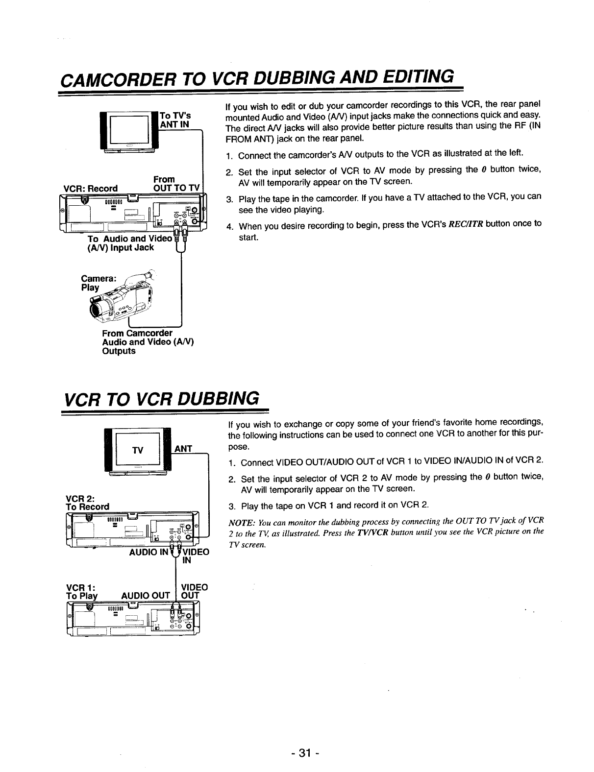
CAMCORDER TO VCR DUBBING AND EDITING
To TV's
ANT IN
VCR: Record From
OUT TO TV
To Audio and Video
(AN) Input Jack
If you wish to edit or dub your camcorder recordings to this VCR, the rear panel
mounted Audio and Video (A/V) input jacks make the connections quick and easy.
The direct A/V jacks will also provide better picture results than using the RF (IN
FROM ANT) jack on the rear panel.
1. Connect the camcorder's A/V outputs to the VCR as illustrated at the left.
2. Set the input selector of VCR to AV mode by pressing the 0button twice,
AV will temporarily appear on the TV screen.
3. Play the tape in the camcorder. If you have a TV attached to the VCR, you can
see the video playing.
4. When you desire recording to begin, press the VCR's REC/ITR button once to
start.
Camera: -_
From Camcorder
Audio and Video (AN)
Outputs
VCR TO VCR DUBBING
UANT
VCR 2:
To Record
VCR 1:
To Play AUDIO OUT VIDEO
OUT
If you wish to exchange or copy some of your friend's favorite home recordings,
the following instructions can be used to connect one VCR to another for this pur-
pose.
1. Connect VIDEO OUT/AUDIO OUT of VCR 1 to VIDEO IN/AUDIO IN of VCR 2.
2. Set the input selector of VCR 2 to AV mode by pressing the 0button twice,
AV will temporarily appear on the TV screen.
3. Play the tape on VCR 1 and record it on VCR 2.
NOTE: You can monitor the dubbing process by connecting the OUT TO TVjack of VCR
2 to the T_, as illustrated. Press the TV/VCR button until you see the VCR picture on the
TV screen,
-31 -
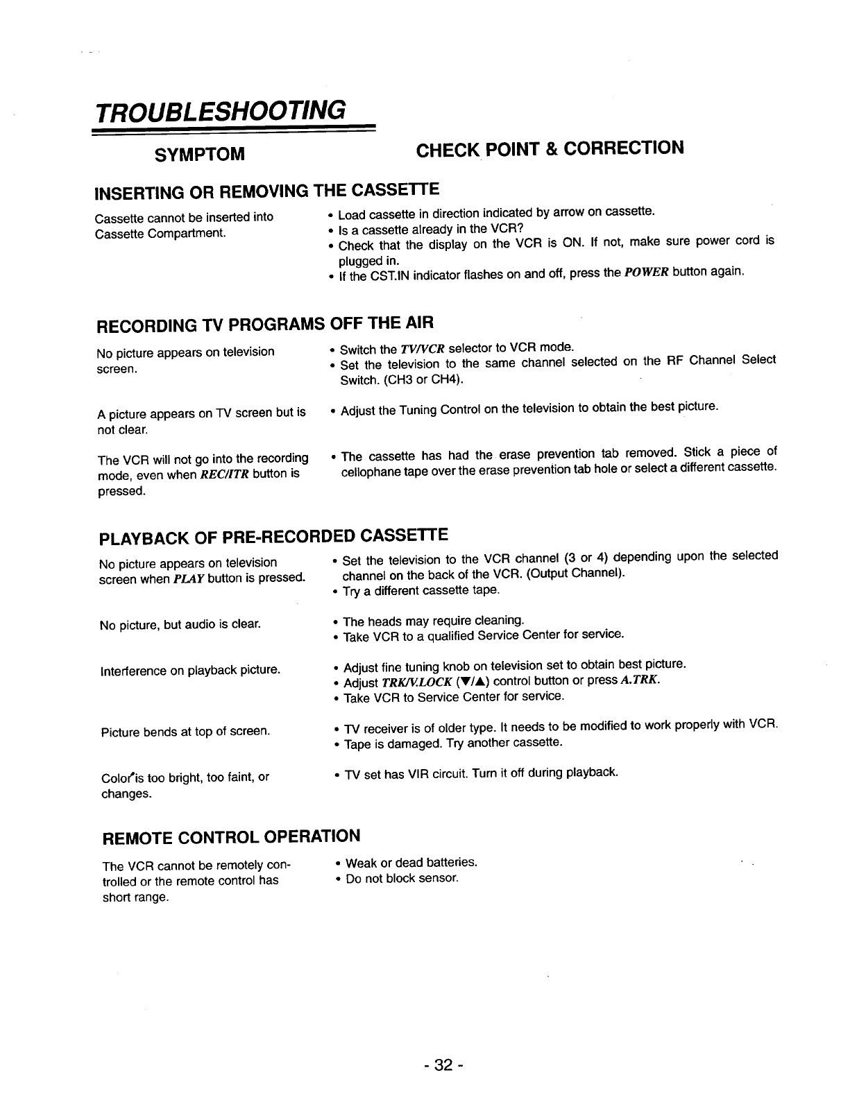
TROUBLESHOOTING
SYMPTOM CHECK POINT & CORRECTION
INSERTING OR REMOVING THE CASSETTE
Cassette cannot be inserted into •Load cassette in direction indicated by arrow on cassette.
Cassette Compartment. •Is a cassette already in the VCR?
•Check that the display on the VCR is ON. If not, make sure power cord is
plugged in.
•If the CST.IN indicator flashes on and off, press the POWER button again.
RECORDING TV PROGRAMS OFF THE AIR
No picture appears on television •Switch the TV/VGR selector to VCR mode.
screen. •Set the television to the same channel selected on the RF Channel Select
Switch. (CH3 or CH4).
A picture appears on "IV screen but is
not clear.
• Adjust the Tuning Control on the television to obtain the best picture.
The VCR will not go into the recording
mode, even when REC/ITR button is
pressed.
•The cassette has had the erase prevention tab removed. Stick apiece of
cellophanetape overthe erase preventiontab holeorselecta differentcassette.
PLAYBACK OF PRE-RECORDED CASSETTE
No picture appears on television •Set the television to the VCR channel (3 or 4) depending upon the selected
screen when PLAY button is pressed, channel on the back of the VCR. (Output Channel).
• Try adifferent cassette tape.
No picture, but audio is clear. •The heads may require cleaning.
•Take VCR to a qualified Service Center for service.
Interference on playback picture. • Adjust fine tuning knob on television set to obtain best picture.
• Adjust TRK/V..LOCK (V/A) control button or press A.TRK.
• Take VCR to Service Center for service.
Picture bends at top of screen. •TV receiver is of older type. It needs to be modified to work properly with VCR.
•Tape is damaged. Try another cassette.
Colo('is too bright, too faint, or
changes.
•IV set has VIR circuit. Turn it off during playback.
REMOTE CONTROL OPERATION
The VCR cannot be remotely con- •Weak or dead batteries.
trolled or the remote control has • Do not block sensor.
short range.
- 32 -
SYMPTOM CHECK POINT & CORRECTION
CLOCK
-- :.... appears on the -IV screen.
VCR does not start at preset record
starting time.
VCR does not start at preset record
starting time.
The tape is ejected in the timer mode.
CST.IN indication flashes.
Power indicator flashes.
•Reset time according to instructions. Power has been interrupted.
•Setup recording time according to instructions.
•Be sure the AM-PM display is correct.
•The cassette has had the erase prevention tab removed. Stick a piece of cello-
phane tape over the erase prevention tab hole or select a different cassette.
• Insert a cassette.
•Unplug the VCR; after 3 seconds, put the plug in again.
VIDEO HEAD CLEANING
Picture playback may become blurred or interrupted even though the TV pro-
gram received is clear. This does not mean that the recorded program has
been erased.
Dirt accumulation on the head after long periods of use can cause these prob-
lems.
If high quality video tapes are used in this VCR, the video heads should not
require cleaning because of the built-in automatic head cleaner. However, it is
possible that the heads may become clogged when playing an old or damaged
tape. If the image on your screen resembles the picture on the left while play-
ing back a tape, the heads may require cleaning.
To clean the heads, obtain a head cleaning tape from your local video dealer.
Be sure to follow the instructions that come with the cleaning tape, as exces-
sive use can shorten head life.
- 33 -
SPECIFICATIONS
Power Source
PowerConsumption
Head System
Tape Speed
Tape Width
Maximum Recording Time
Rewind Time
Video
Video Signal System
Channel Coverage
Input
Output
Signal to Noise Ratio
Audio
Input
Output
SIN Ratio
Type
Antenna
VHF Output Signal
Dimensions
Operating Temperature
Operating Humidity
Timer
Weight
(SP)
(LP)
(EP)
(SP)
(EP)
(VHF)
(UHF)
(CATV)
(LINE)
(LINE)
(UHF)
(VRF)
(WxHxD)
AC 120V, 60Hz
Approx. 16 Watts
Four head helical scan azimuth system
33.35 mm/sec
16.67 mm/sec
11.12 mmfsec
12.7 mm
2 HOURS (T-120)
6 HOURS (T-120)
8 HOURS (T-160)
Less than 210 seconds (T-120)
EIA Standard (525 lines, 60 fields)
NTSC type color signal
2-13
14-69
4A, A-W, W+1~W+84, A-5~A-1
1.0 Vp-p 75 ohms unbalanced
1.0 Vp-p 75 ohms unbalanced
More than 45 dB (at SP mode)
-7.8 dBm
-7.8 dBm
More than 40 dB (at SP mode)
Monaural type
75 ohms
75 ohms
Channel 3 or 4 (Switchable)
360 x 92 x 283 mm (14.2" x 3.6" x 11.1")
5 °C~35 "C (41 °F~95 °F)
Less than 80% RH
12-hour display type with AM, PM
Approx. 4.4 Kg (9.7 Ibs)
* Designs and specifications are subject to change without notice.
* Weight and dimensions shown are approximate.
- 34 -

GOLDSTAR VCR
LIMITED WA NTY
LG Electronics U.S.A., Inc. will repair or at its option replace, without charge, your product which proves to be
defective in material or workmanship under normal use, during the warranty period listed below from the date of
original purchase. This warranty is good only to the original purchaser of the product during the v_arranty
period as long as it is in the U.S. including Alaska, Hawaii and U.S. Territories.
WARRANTY PERIOD
MODEL #LABOR PARTS
GVR-F435 90 days 1Year
HOW SERVICE IS HANDLED
Call 1-800-243-0000, Option # 1 24 hrs. a day,
7 days per week, please have your product type
(Monitor, TV, VCR) and ZIP code ready.
No other express warranty is applicable to this product. THE DURATION OF ANY IMPLIED WARRANTIES,
INCLUDING THE IMPLIED WARRANTY OF MERCHANTABILITY, IS LIMITED TO THE
DURATION OF THE EXPRESS WARRANTY HEREIN. LG ELECTRONICS U.S.A., INC. SHALL NOT
BE LIABLE FOR THE LOSS OF THE USE OF THE PRODUCT, INCONVENIENCE, LOSS OR ANY
OTHER DAMAGES, DIRECT OR CONSEQUENTIAL, ARISING OUT OF THE USE OF, OR
INABILITY TO USE, THIS PRODUCT OR FOR ANY BREACH OF ANY EXPRESS OR IMPLIED
WARRANTY, INCLUDING THE IMPLIED WARRANTY OF MERCHANTABILITY APPLICABLE TO
THIS PRODUCT.
Some states do not allow the exclusion or limitation of incidental or consequential damages or limitations on how
long an implied warranty lasts; so these limitations or exclusions may not apply to you. This warranty gives you
specific legal rights and you may also have other rights which vary from state to state.
THE ABOVE WARRANTY DOES NOT APPLY:
•To damages or problems which result from delivery or improper installation.
•To damages or problems which result from misuse, abuse, accident, alteration, or incorrect electrical current or
voltage.
•To service calls, which do not involve defective workmanship or material, such as head cleaning and explaining
the operation of the unit.
Therefore, these costs are paid by the consumer.
CUSTOMER ASSISTANCE NUMBERS:
To Prove Warranty Coverage: -_ Retain your Sales Receipt to prove date of purchase.
--> Copy of your Sales Receipt must be submitted at the time
warranty service is provided.
To Obtain Product, Customer or
Service Assistance:
---> Call 1-800-243-0000, (Mon-Fri 7am-7pm CST)
Push appropriate menu code.
To Obtain Nearest Authorized Service -->
Center, Parts Distributor or Sales Dealer:
Call 1-800-243-0000, Push option #124 hrs. a day, 7 days
per week, please have your product type (Monitor, TV, VCR)
and ZIP code ready.
P/N 3834RM0001A Printed in Korea
