GOODMAN Furnace/Heater, Gas Manual L0806734
User Manual: GOODMAN GOODMAN Furnace/Heater, Gas Manual GOODMAN Furnace/Heater, Gas Owner's Manual, GOODMAN Furnace/Heater, Gas installation guides
Open the PDF directly: View PDF ![]() .
.
Page Count: 40
GMV95/GCV9
TWO-STAGE GAS-FIRED WARM AIR FURNACE
INSTALLATION INSTRUCTIONS
Installer. Affix all manuals adjacent to the unit.
(Type FSP CATEGORY IV Direct or Non Direct Vent Air Furnace)
April 17, 2008 @ 4:09 pm
These furnaces comply with requirements
embodied in the American National Standard
/National Standard of Canada ANSI
Z21.47.CSA-2.3 Gas Fired Central Furnaces.
_k RECOGNIZE THIS SYMBOL AS A SAFETY PRECAUTION.
ATTENTION INSTALLING PERSONNEL
As a professional installer you have an obligation to know the product better than the customer. This includes all safety
precautions and related items.
Prior to actual installation, thoroughly familiarize yourself with this Instruction Manual. Pay special attention to all safety
warnings. Often during installation or repair it is possible to place yourself in a position which is more hazardous than
when the unit is in operation.
Remember, it is your responsibility to install the product safely and to know it well enough to be able to instruct a
customer in its safe use.
Safety is a matter of common sense...a matter of thinking before acting. Most dealers have a list of specific good safety
practices...follow them.
The precautions listed in this Installation Manual are intended as supplemental to existing practices. However, if there is
a direct conflict between existing practices and the content of this manual, the precautions listed here take precedence.
*NOTE: Please contact your distributor or our
website for the applicable Specification Sheet
referred to in this manual.
IO-280J
Goodman Manufacturing Company, L.P.
5151 San Fetipe, Suite 500, Houston, TX 77056
www. cioodmanmfcL corn
© 2004-2008 Goodman Manufacturing Company, L.P. 4/08
Table of Contents
I. Component identification ............................................................................................................................................... 5
II. Safety .............................................................................................................................................................................. 6
ELECTROSTATIC DISCHARGE (ESD) PRECAUTIONS ................................................................................................... 6
ill. Product Application ...................................................................................................................................................... 6
IV. Location Requirements & Considerations .................................................................................................................. 7
GENERAL ......................................................................................................................................................... 7
CLEARANCES AND ACCESSIBILITY ........................................................................................................................... 8
FURNACE SUSPENSION ........................................................................................................................................ 8
EXISTING FURNACE REMOVAL .............................................................................................................................. 8
THERMOSTAT LOCATION ....................................................................................................................................... 9
V. Combustion & Ventilation Air Requirements ............................................................................................................... 9
VI. Installation Positions ................................................................................................................................................... 11
Vii. Horizontal Applications &Considerations ................................................................................................................ 11
GENERAL ........................................................................................................................................................ 11
DRAIN TRAP AND LINES ..................................................................................................................................... 11
LEVELING ........................................................................................................................................................ 11
ALTERNATE VENT/FLuE AND COMBUSTION AIR CONNECTIONS ..................................................................................... 11
ALTERNATE ELECTRICAL AND GAS LINE CONNECTIONS ............................................................................................ 12
DRAIN PAN ..................................................................................................................................................... 12
FREEZE PROTECTION ........................................................................................................................................ 12
FURNACE SUSPENSION ...................................................................................................................................... 12
Viii. Propane Gas/High Altitude installations ............................................................................................................... 12
iX. Vent]Flue Pipe & Combustion Air Pipe ..................................................................................................................... 12
GENERAL ....................................................................................................................................................... 12
DUAL CERTIFICATION: NoN=DIRECT/DIRECT VENT ................................................................................................... 12
MATERIALS AND JOINING METHODS ..................................................................................................................... 13
PROPER VENT/FLuE AND COMBUSTION AIR PiPiNG PRACTICES ................................................................................. 13
TERMINATION LOCATIONS ................................................................................................................................... 13
CANADIAN VENTING REQUIREMENTS ..................................................................................................................... 13
STANDARD FURNACE CONNECTIONS ..................................................................................................................... 14
ALTERNATE FURNACE CONNECTIONS ..................................................................................................................... 14
NoN=DIRECT VENT (SINGLE PIPE) PIPING ............................................................................................................ 16
DIRECT VENT (DUAL PIPE) PIPING ...................................................................................................................... 17
VENT/INTAKE TERMINATIONS FOR INSTALLATION OF MULTIPLE DIRECT VENT FURNACES .................................................. 18
CONCENTRIC VENT TERMINATION ......................................................................................................................... 19
SIDE WALL VENT KIT ........................................................................................................................................ 19
X. Condensate Drain Lines &Drain Trap ........................................................................................................................ 19
GENERAL ....................................................................................................................................................... 19
UPRIGHT _NSTALLATIONS ..................................................................................................................................... 19
HORIZONTAL INSTALLATIONS ................................................................................................................................ 20
Xi. Electrical Connections ................................................................................................................................................ 21
WiRiNG HARNESS ............................................................................................................................................ 21
115 VOLT LINE CONNECTIONS ............................................................................................................................ 22
24 VOLT THERMOSTAT WIRING ............................................................................................................................ 22
SINGLE-STAGE TH ERMOSTAT APPLICATION ............................................................................................................. 23
24 VOLT DEHUMIDISTAT WIRING .......................................................................................................................... 23
FOSSIL FUEL APPLICATIONS ............................................................................................................................... 23
115 VOLT LINE CONNECTION OF ACCESSORIES (HuMIDIFiER AND ELECTRONIC AIR CLEANER) ....................................... 23
24 VOLT HUMIDIFIER ........................................................................................................................................ 24
Xll. Gas Supply and Piping .............................................................................................................................................. 24
GENERAL ....................................................................................................................................................... 24
GAS PIPING CONNECTIONS ................................................................................................................................ 24
PROPANE GAS TANKS AND PIPING ...................................................................................................................... 26
Xlll. Circulating Air & Filters ............................................................................................................................................ 27
DUCTWORK =AIR FLOW ..................................................................................................................................... 27
BOTTOM RETURN AIR OPENING [UPFLOW MODELS] ............................................................................................... 27
FILTERS = READ THIS SECTION BEFORE _NSTALLING THE RETURN AIR DUCTWORK ....................................................... 27
UPRIGHT _NSTALLATIONS ..................................................................................................................................... 28
HORIZONTAL INSTALLATIONS ................................................................................................................................ 28
Table of Contents
XIV. Startup Procedure & Adjustment ............................................................................................................................. 28
HEATANTICIPATOR SETTING ................................................................................................................................ 28
DRAIN TRAP PRIMING .......................................................................................................................................28
FURNACE OPERATION ........................................................................................................................................28
GAS SUPPLY PRESSURE MEASUREMENT .............................................................................................................. 28
GAS MANIFOLD PRESSURE MEASUREMENT AND ADJUSTMENT .................................................................................. 29
GAS INPUT RATE MEASUREMENT (NATURAL GAS ONLY) .........................................................................................29
TEMPERATURERISE ......................................................................................................................................... 30
CIRCULATOR BLOWER SPEEDS ........................................................................................................................... 30
BLOWER HEAT OFF DELAY TIMINGS ................................................................................................................... 32
XV. Normal Sequence of Operation ................................................................................................................................ 32
POWERUP ..................................................................................................................................................... 32
HEATING MODE ............................................................................................................................................... 32
COOLING MODE .............................................................................................................................................. 33
FAN ONLY MODE ............................................................................................................................................. 33
XVl. Operational Checks .................................................................................................................................................. 33
BURNER FLAME ............................................................................................................................................... 33
XVll. Safety Circuit Description ....................................................................................................................................... 33
GENERAL ....................................................................................................................................................... 33
INTEGRATED CONTROL MODULE .......................................................................................................................... 33
PRIMARY LIMIT ................................................................................................................................................ 33
AUXILIARY LIMIT ............................................................................................................................................... 34
ROLLOUT LIMIT ................................................................................................................................................ 34
PRESSURE SWITCHES ........................................................................................................................................ 34
FLAME SENSOR ............................................................................................................................................... 34
XVlll. Troubleshooting ...................................................................................................................................................... 34
ELECTROSTATIC DISCHARGE (ESD) PRECAUTIONS ................................................................................................. 34
DIAGNOSTIC CHART .......................................................................................................................................... 34
RESETTING FROM LOCKOUT ............................................................................................................................... 34
XlX. Maintenance ............................................................................................................................................................. 34
ANNUAL INSPECTION .......................................................................................................................................... 34
FILTERS .......................................................................................................................................................... 35
BURNERS ....................................................................................................................................................... 35
INDUCED DRAFT AND CIRCULATOR BLOWERS ......................................................................................................... 35
CONDENSATE TRAP AND DRAIN SYSTEM (QUALIFIED SERVICER ONLY) ...................................................................... 35
FLAME SENSOR (QUALIFIED SERVICER ONLY) ...................................................................................................... 35
FLUE PASSAGES (QUALIFIED SERVICER ONLY) ..................................................................................................... 35
XX. Internal Filter Removal ............................................................................................................................................. 35
XXl. Before Leaving an Installation ................................................................................................................................ 36
XXII. Repair & Replacement Parts .................................................................................................................................. 36
APPENDIX
Troubleshooting Chart ...................................................................................................................................................... 37
Wiring Diagram ............................................................................................................................................................... 39
All, WARNING
GOODMAN WILL NOT BE RESPONSIBLE FOR ANY INJURY OR
PROPERTY DAMAGE ARISING FROM IMPROPER SERVICE OR SERVICE
PROCEDURES. IF YOU INSTALL OR PERFORM SERVICE ON THIS UNIT_
YOU ASSUME RESPONSIBILITY FOR ANY PERSONAL INJURY OR
PROPERTY DAMAGE WHICH MAY RESULT. MANY JURISDICTIONS
REQUIRE A LICENSE TO INSTALL OR SERVICE HEATING AND AIR
CONDITIONING EQUIPMENT.
_lb WARNING
IF THE INFORMATION IN THESE INSTRUCTIONS IS NOT FOLLOWED
EXACTLY_ A FIRE OR EXPLOSION MAY RESULT CAUSING PROPERTY
DAMAGE_ PERSONAL INJURY OR LOSS OF LIFE.
=Do NOT STORE OR USE GASOLINE OR OTHER FLAMMABLE VAPORS
AND LIQUIDS IN THE VICINITY OF THIS OR ANY OTHER APPLIANCE.
-WHAT TO DO IF YOU SMELL GAS:
* Do NOT TRY TO LIGHT ANY APPLIANCE.
* Do NOT TOUCH ANY ELECTRICAL SWITCH; DO NOT USE
ANY PHONE IN YOUR BUILDING.
*IMMEDIATELY CALL YOUR GAS SUPPLIER FROM A
NEIGHBORS PHONE. FOLLOW THE GAS SUPPLIERS
INSTRUCTIONS.
*IF YOU CANNOT READCH YOUR GAS SUPPLIER_ CALL THE
FIRE DEPARTMENT.
=INSTALLATION AND SERVICE MUST BE PERFORMED BY A QUALIFIED
INSTALLER_ SERVICE AGENCY OR THE GAS SUPPLIER
_lb WARNING
SHOULD OVERHEATING OCCUR OR THE GAS SUPPLY FAIL TO SHUT
OFF, TURN OFF THE MANUAL GAS SHUTOFF VALVE EXTERNAL TO THE
FURNACE BEFORE TURNING OFF THE ELECTRICAL SUPPLY.
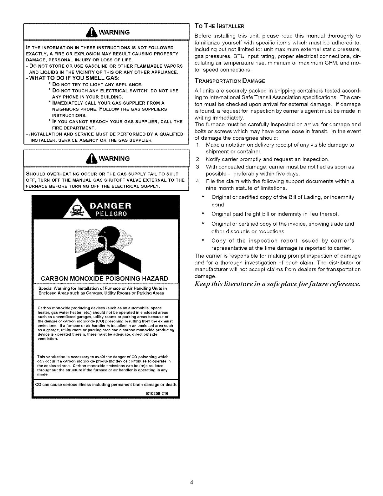
CARBON MONOXIDE POISONING HAZARD
SpecialWarningfor Installationof FurnaceorAir HandlingUnitsin
EnclosedAreassuchas Garages,UtilityRoomsorParkingAreas
Carbon monoxide producing devices (such as an automobile, space
heater, gas water heater, etc.) should not be operated in enclosed areas
such as unventilated garages, utility rooms or parking areas because of
the danger of carbon monoxide (CO) poisoning resulting from the exhaust
emissions. If a furnace or air handler is installed in an enclosed area such
as a garage, utility room or parking area and a carbon monoxide producing
device is operated therein, there must be adequate, direct outside
ventilation.
This ventilation is necessary to avoid the danger of CO poisoning which
can occur if acarbon monoxide producing device continues to operate in
the enclosed area. Carbon monoxide emissions can be (re)circulated
throughout the structure if the furnace or air handler is operating in any
mode.
CO can cause serious illness including permanent brain damage or death.
B10259-216
To THE INSTALLER
Before installing this unit, please read this manual thoroughly to
familiarize yourself with specific items which must be adhered to,
including but not limited to: unit maximum external static pressure,
gas pressures, BTU input rating, proper electrical connections, cir-
culating air temperature rise, minimum or maximum CFM, and mo-
tor speed connections.
TRANSPORTATION DAMAGE
All units are securely packed in shipping containers tested accord-
ing to International Safe Transit Association specifications. The car-
ton must be checked upon arrival for external damage. If damage
is found, a request for inspection by carrier's agent must be made in
writing immediately.
The furnace must be carefully inspected on arrival for damage and
bolts or screws which may have come loose in transit. In the event
of damage the consignee should:
1. Make a notation on delivery receipt of any visible damage to
shipment or container.
2. Notify carrier promptly and request an inspection.
3. With concealed damage, carrier must be notified as soon as
possible - preferably within five days.
4. File the claim with the following support documents within a
nine month statute of limitations.
" Original or certified copy of the Bill of Lading, or indemnity
bond.
° Original paid freight bill or indemnity in lieu thereof.
" Original or certified copy of the invoice, showing trade and
other discounts or reductions.
° Copy of the inspection report issued by carrier's
representative at the time damage is reported to carrier.
The carrier is responsible for making prompt inspection of damage
and for a thorough investigation of each claim. The distributor or
manufacturer will not accept claims from dealers for transportation
damage.
Keep this literature in a safe place for futt;re reference.
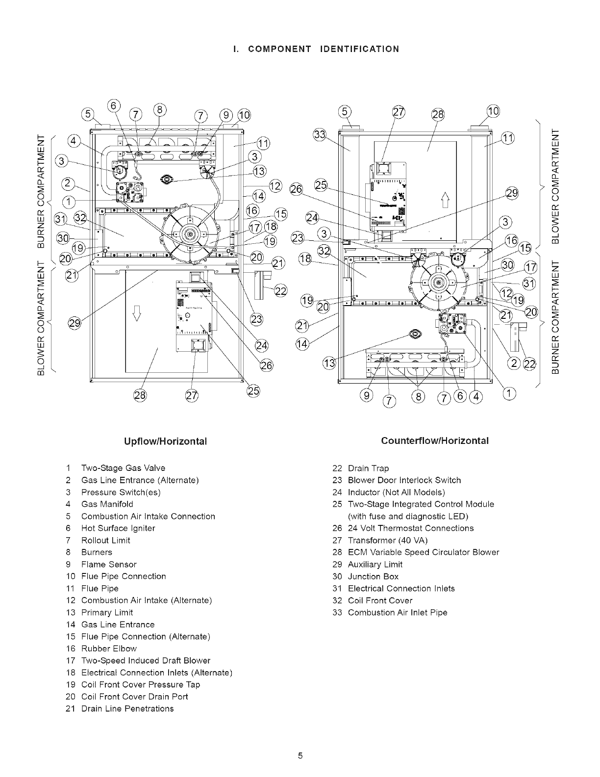
I, COMPONENT IDENTIFICATION
//
1"_........ _,,
o/
F-
Z
LO
n_
0-
0
0
n_
LU
©
__1
m
z
LO
p-
n_
0-
0
0
n_
LO
Z
0_
m
Upflow/Horizontal Cou nterflow/Horizontal
1 Two-Stage Gas Valve
2 Gas Line Entrance (Alternate)
3 Pressure Switch(es)
4 Gas Manifold
5 Combustion Air intake Connection
6 Hot Surface igniter
7 Rollout Limit
8 Burners
9 Flame Sensor
10 Flue Pipe Connection
11 Flue Pipe
12 Combustion Air Intake (Alternate)
13 Primary Limit
14 Gas Line Entrance
15 Flue Pipe Connection (Alternate)
16 Rubber Elbow
17 Two-Speed Induced Draft Blower
18 Electrical Connection Inlets (Alternate)
19 Coil Front Cover Pressure Tap
20 Coil Front Cover Drain Port
21 Drain Line Penetrations
22 Drain Trap
23 Blower Door Interlock Switch
24 Inductor (Not All Models)
25 Two-Stage Integrated Control Module
(with fuse and diagnostic LED)
26 24 Volt Thermostat Connections
27 Transformer (40 VA)
28 ECM Variable Speed Circulator Blower
29 Auxiliary Limit
30 Junction Box
31 Electrical Connection Inlets
32 Coil Front Cover
33 Combustion Air Inlet Pipe
il.SAFETY
Please adhere to the following warnings and cautions when in-
stalling, adjusting, altering, servicing, or operating the furnace.
i_lb WARNING
TO PREVENT PERSONAL INJURY OR DEATH DUE TO IMPROPER
INSTALLATION_ADJUSTMENT_ ALTERATION, SERVICE OR
MAINTENANCE, REFER TO THIS MANUAL. FOR ADDITIONAL
ASSISTANCE OR INFORMATION, CONSULT A QUALIFIED INSTALLER,
SERVICE AGENCY OR THE GAS SUPPLIER.
,_ WARNING
THIS PRODUCT CONTAINS OR PRODUCES A CHEMICAL OR CHEMICALS
WHICH MAY CAUSE SERIOUS ILLNESS OR DEATH AND WHICH ARE
KNOWN TO THE STATE OF CALIFORNIA TO CAUSE CANCER_ BIRTH
DEFECTS OR OTHER REPRODUCTIVE HARM.
I_lb WARNING
ITo PREVENT POSSIBLE PROPERTY DAMAGE, PERSONAL INJURY OR DEATH
LO ,CCAo M "oOC NT?;R O%% USTBELOCATBDTOPROTECT
i_lb WARNING
Do NOT UTILIZE THE HEATING UNIT WITHOUT REASONABLE ROUTINE
INSPECTION, MAINTENANCE AND SUPERVISION. IF THE UNIT IS IN A
BUILDING THAT IS OR WILL BE VACANT, CARE SHOULD BE TAKEN TO
ROUTINELY INSPECT_ MAINTAIN AND MONITOR THE UNIT. IN THE
EVENT THAT THE BUILDING MAY BE EXPOSED TO FREEZING
TEMPERATURES AND WILL BE VACANT, DRAIN ALL WATER-BEARING
PIPES, PROPERLY WINTERIZE THE BUILDING_ AND TURN OFF ALL
WATER SOURCES. IN THE EVENT THAT THE BUILDING IS EXPOSED TO
FREEZING TEMPERATURES AND IS VACANT, ANY HYDRONIC COIL
UNITS SHOULD ALSO BE DRAINED AND AN ALTERNATIVE HEAT
SOURCES UTILIZED.
ELECTROSTATIC DISCHARGE (ESD) PRECAUTIONS
NOTE: Discharge static electricity accumulated in the body before
touching the unit. An electrostatic discharge can adversely affect
electrical components.
Use the following precautions during furnace installation and ser-
vicing to protect the integrated control module from damage. By
putting the furnace, the control, and the person at the same electro-
static potential, these steps will help avoid exposing the integrated
control module to electrostatic discharge. This procedure is appli-
cable to both installed and non-installed (ungrounded) furnaces.
1. Disconnect all power to the furnace. Do not touch the
integrated control module or any wire connected to the control
prior to discharging your body's electrostatic charge to
ground.
2. Firmly touch a clean, unpainted, metal surface of the furnace
near the control. Any tools held in a person's hand during
grounding will be discharged.
3. Service integrated control module or connecting wiring
following the discharge process in step 2. Use caution not
to recharge your body with static electricity; (i.e., do not move
or shuffle your feet, do not touch ungrounded objects, etc.).
If you come in contact with an ungrounded object, repeat
step 2 before touching control or wires.
4. Discharge your body to ground before removing a new
control from its container. Follow steps 1 through 3 if
installing the control on a furnace. Return any old or new
controls to their containers before touching any ungrounded
object.
III. PRODUCT APPLICATION
This furnace is primarily designed for residential home-heating
applications. It is NOT designed or certified for use in mobile
homes, trailers or recreational vehicles. This unit is NOT designed
or certified for outdoor applications. The furnace must be installed
indoors (i.e., attic space, crawl space, or garage area provided the
garage area is enclosed with an operating door).
This furnace can be used in the following non-industrial commer-
cial applications:
Schools, Office buildings, Churches, Retail stores
Nursing homes, Hotels/motels, Common or office areas
In such applications, the furnace must be installed with the follow-
ing stipulations:
It must be installed per the installation instructions
provided and per local and national codes.
It must be installed indoors in a building constructed on
site.
It must be part of a ducted system and not used in a free
air delivery application.
It must not be used as a "make-up" air unit.
It must be installed with two-pipe systems for combustion
air, especially if VOC's or other contaminants are present
in the conditioned space.
All other warranty exclusions and restrictions apply This
furnace is an ETL dual-certified appliance and is
appropriate for use with natural or propane gas (NOTE: If
using propane, a propane conversion kit is required).
Dual certification means that the combustion air inlet pipe is op-
tional and the furnace can be vented as a:
Non-direct vent (single pipe) central forced air furnace in
which combustion air is taken from the installation area
or from air ducted from the outside or,
Direct vent (dual pipe) central forced air furnace in which
all combustion air supplied directly to the furnace burners
through a special air intake system outlined in these
instructions.
This furnace may be used as a construction site heater ONLY if the
following conditions are met:
The vent system is permanently installed per these
installation instructions.
A room thermostat is used to control the furnace. Fixed
jumpers that provide continuous heating CANNOT be
used.
Return air ducts are provided and sealed to the furnace.
A return air temperature range between 60°F (16°C) and
80°F (27°C) is maintained.
Air filters are installed in the system and maintained
during construction, replaced as appropriate during
construction, and upon completion of construction are
replaced.. The input rate and temperature rise are set
per the furnace rating plate.
The input rate and temperature rise are set per the furnace
rating plate.
100% outside air is provided for combustion air
requirements during construction. Temporary ducting can
be used.
NOTE:Donotconnectthetemporaryductdirectlytothe
furnace.Theductmustbesizedaccordingto the
instructionsunderSection V, Combustion and Ventilation
Air Requirements, Section 5.3.3.
The furnace heat exchanger, components, duct system,
air filters and evaporator coils are thoroughly cleaned
following final construction clean up.
All furnace operating conditions (including ignition, input
rate, temperature rise and venting) are verified according
to these installation instructions.
NOTE: The Commonwealth of Massachusetts requires that the
following additional requirements must also be met:
Gas furnaces must be installed by a licensed plumber or
gas fitter.
A T-handle gas cock must be used.
If the unit is to be installed in an attic, the passageway to
and the service area around the unit must have flooring.
To ensure proper installation and operation, thoroughly read this
manual for specifics pertaining to the installation and application
of this product.
_b WARNING
POSSIBLE PROPERTY DAMAGE, PERSONAL INJURY OR DEATH DUE TO
FIRE_ EXPLOSION_ SMOKE_ SOOT_ CONDENSATION_ ELECTRICAL
SHOCK OR CARBON MONOXIDE MAY RESULT FROM IMPROPER
INSTALLATION_ REPAIR, OPERATION_ OR MAINTENANCE OF THIS
PRODUCT.
,_ WARNING
TO PREVENT PERSONAL INJURY, PROPERTY DAMAGE OR DEATH DUE
TO FIRE, DO NOT INSTALL THIS FURNACE IN A MOBILE HOME_
TRAILER OR RECREATIONAL VEHICLE.
To ensure proper furnace operation, install, operate and maintain
the furnace in accordance with these installation and operation
instructions, all local building codes and ordinances. In their ab-
sence, follow the latest edition of the National Fuel Gas Code
(NFPA 54/ANSI Z223.1 ), and/or CAN/CSA B 149.1-05 Installation
Codes, local plumbing or waste water codes, and other applicable
codes.
A copy of the National Fuel Gas Code (NFPA 54/ANSI Z223.1 ) can
be obtained from any of the following:
American National Standards Institute
1430 Broadway
NewYork, NY 10018
National Fire Protection Association
1 Batterymarch Park
Quincy, MA 02269
CSA International
8501 East Pleasant Valley
Cleveland, OH 44131
A copy of the CAN/CSA B149.1-05 Installation Codes can also be
obtained from:
CSA International
178 Rexdale Boulevard
Etobicoke, Ontario, Canada M9W 1R3
The rated heating capacity of the furnace should be greater than or
equal to the total heat loss of the area to be heated. The total heat
loss should be calculated by an approved method or in accor-
dance with "ASHRAE Guide" or "Manual J-Load Calculations" pub-
lished by the Air Conditioning Contractors of America.
IV.LOCATION REQUIREMENTS & CONSIDERATIONS
GENERAL
,_ WARNING
To PREVENT POSSIBLE EQUIPMENT DAMAGE, PROPERTY DAMAGE,
PERSONAL INJURY OR DEATH, THE FOLLOWING BULLET POINTS MUST
BE OBSERVED WHEN INSTALLING THE UNIT.
Follow the instructions listed below when selecting a furnace loca-
tion. Refer also to the guidelines provided in Section V, Combus-
tion and Ventilation Air Requirements.
Centrally locate the furnace with respect to the proposed
or existing air distribution system.
Ensure the temperature of the return air entering the
furnace is between 55°F and 100°F when the furnace is
heating.
Provide provisions for venting combustion products
outdoors through a proper venting system. Special
consideration should be given to vent/flue pipe routing
and combustion air intake pipe when applicable. Refer
to Section IX, Vent/Flue Pipe and Combustion Air Pipe -
Termination Locations for appropriate termination
locations and to determine if the piping system from
furnace to termination can be accomplished within the
guidelines given. NOTE: The length of flue and/or
combustion air piping can be a limiting factor in the
location of the furnace.
Locate the furnace so condensate flows downwards to
the drain. Do not locate the furnace or its condensate
drainage system in any area subject to below freezing
temperatures without proper freeze protection. Refer to
Section X, Condensate Drain Lines and Trap for further
details.
Ensure adequate combustion air is available for the
furnace. Improper or insufficient combustion air can
expose building occupants to gas combustion products
that could include carbon monoxide. Refer to Section V,
Combustion and Ventilation Air Requirements.
Set the furnace on a level floor to enable proper
condensate drainage. If the floor becomes wet or damp
at times, place the furnace above the floor on a concrete
base sized approximately 1-1/2" larger than the base of
the furnace. Refer to the Section VII, Horizontal
Appfications and Considerations for leveling of horizontal
furnaces.
Ensure upflow or horizontal furnaces are not installed
directly on carpeting, or any other combustible material.
The only combustible material allowed is wood.
A special accessory subbase must be used for upright
counterflow unit installations over any combustible
material (including wood). Refer to subbase instructions
for installation details. (NOTE: A subbase will not be
required if an air conditioning coil is located beneath the
furnace between the supply air opening and the
combustible floor.
Exposure to contaminated combustion air will result in
safety and performance-related problems. Do not install
the furnace where the combustion air is exposed to the
following substances:
chlorinated waxes or cleaners
chlorine-based swimming pool chemicals
water softening chemicals
deicingsaltsorchemicals
carbontetrachloride
halogentyperefrigerants
cleaningsolutions(suchasperchloroethylene)
printinginks
paintremovers
varnishes
hydrochloricacid
cementsandglues
antistaticfabricsoftenersforclothesdryers
andmasonryacidwashingmaterials
Sealoffanon-direct vent furnace if it is installed near an
area frequently contaminated by any of the above
substances. This protects the non-direct vent furnace
from airborne contaminants. To ensure that the
enclosed non-direct vent furnace has an adequate supply
of combustion air, vent from a nearby uncontaminated
room or from outdoors. Refer to the Section V,
Combustion and Ventilation Air Requirements for details.
If the furnace is used in connection with a cooling unit,
install the furnace upstream or in parallel with the cooling
unit. Premature heat exchanger failure will result if the
cooling unit is placed ahead of the furnace.
If the furnace is installed in a residential garage, position
the furnace so that the burners and ignition source are
located not less than 18 inches (457 mm) above the floor.
Protect the furnace from physical damage by vehicles.
If the furnace is installed horizontally, the furnace access
doors must be vertical so that the burners fire horizontally
into the heat exchanger. Do not install the unit with the
access doors on the "up/top" or "down/bottom" side of
the furnace.
CLEARANCES AND ACCESSIBILITY
Installations must adhere to the clearances to combustible mate-
rials which this furnace has been design certified to. The mini-
mum clearance information for this furnace is provided on the unit's
clearance label. These clearances must be permanently main-
tained. Clearances must also accommodate an installation's gas,
electrical, drain trap, and drain line connections. If the alternate
combustion air intake or vent/flue connections are used additional
clearance must be provided to accommodate these connections.
Refer to Section IX, Vent Flue Pipe and Combustion Air Pipe for
details. NOTE: In addition to the required clearances to combus-
tible materials, a minimum of 24 inches service clearance must be
available in front of the unit.
TOP
SIDESIDESIDE
TOP
11o0I I
BOTTOM
BOTTOM
Upflow Counterflow Horizontal
A furnace installed in a confined space (i.e., a closet or utility room)
must have two ventilation openings with a total minimum free area
of 0.25 square inches per 1,000 BTU/hr of furnace input rating.
Refer to Specification Sheet applicable to your model* for mini-
mum clearances to combustible surfaces. One of the ventilation
openings must be within 12 inches of the top; the other opening
must be within 12 inches of the bottom of the confined space. In a
typical construction, the clearance between the door and door frame
is usually adequate to satisfy this ventilation requirement.
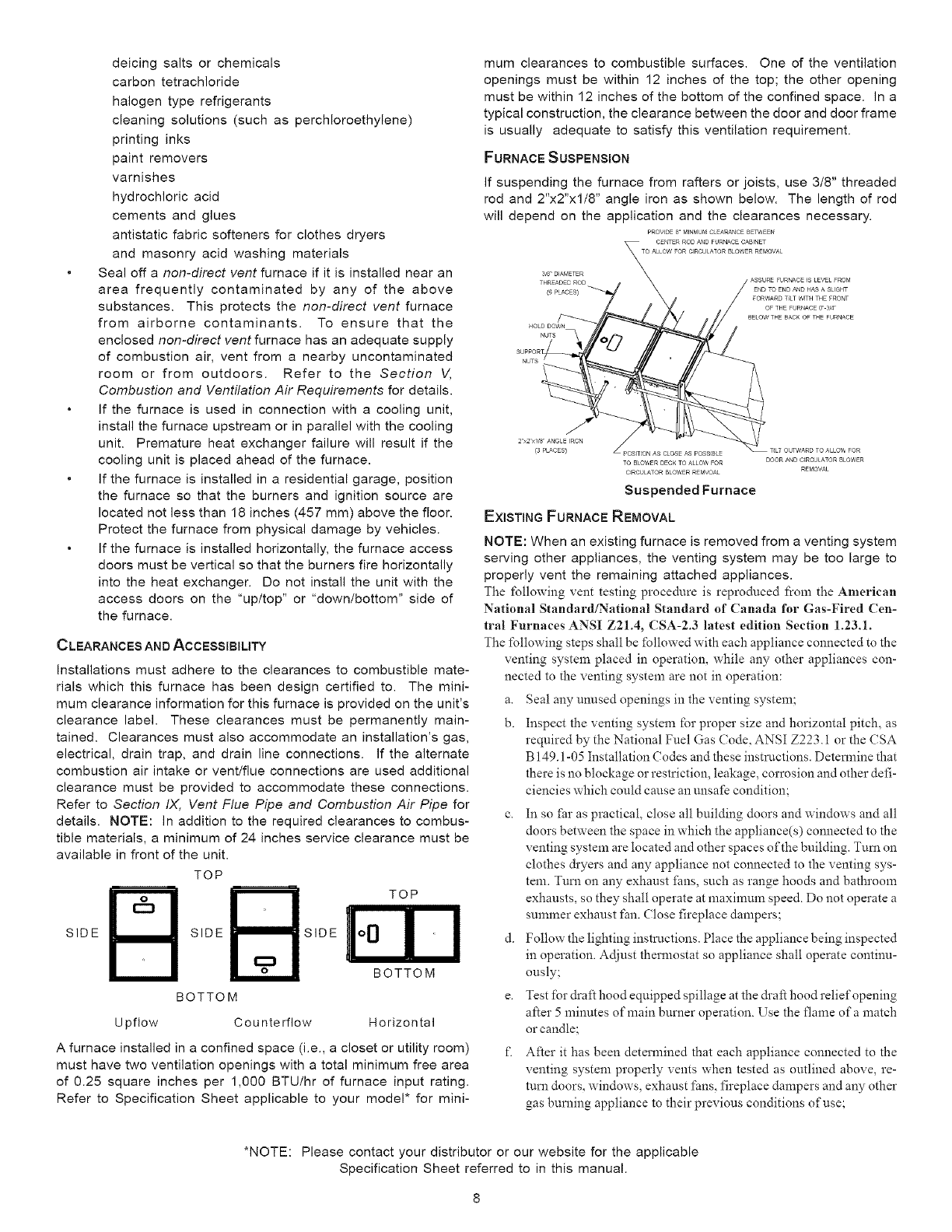
FURNACE SUSPENSION
If suspending the furnace from rafters or joists, use 3/8" threaded
rod and 2"x2"x1/8" angle iron as shown below. The length of rod
will depend on the application and the clearances necessary.
PROVIDE 8 M_NMM CLEARANCE BEW_,EEN
3_8"DIAf_ETER
THREADE0 ROD
(6PLACES}
HOLD DO_N
2"x2"x_/8"ANGL5 _RON
_3PLACES)
TOBLOWERDECKTOA_LO_FOR
CIRCULATORBLOWERREMVOA_
Suspended Furnace
EXISTING FURNACE REMOVAL
DOORA_D CIRCULATORBLOWER
REMOVAL
NOTE: When an existing furnace is removed from a venting system
serving other appliances, the venting system may be too large to
properly vent the remaining attached appliances.
The following vent testing procedure is reproduced from the American
National Standard/National Standard of Canada for Gas-Fired Cen-
tral Furnaces ANSI Z21.4, CSA-2.3 latest edition Section 1.23.1.
The following steps shall be followed with each appliance connected to the
venting system placed in operation, while any other appliances con-
nected to the venting system are not in operation:
a. Seal any unused openings in the venting system;
b. Inspect the venting system for proper size and horizontal pitch, as
required by the National Fuel Gas (;ode, ANSI Z223.1 or the CSA
B 149.1-05 Installation (?odes and these instrnctions. Deterlnine that
there is no blockage or restriction, leakage, corrosion and other defi-
ciencies which could cause an unsafe condition;
c. In so fhr as practical, close all building doors and windows and all
doors between the space in which the appliance(s) connected to the
venting system are located and other spaces of the building. Turn on
clothes &yers and any appliance not connected to the venting sys-
tem. Turn on any exhaust fhns, such as range hoods and bathroom
exhausts, so they shall operate at maximum speed. Do not operate a
summer exhaust fan. (?lose fireplace dampers;
d. Follow the lighting instructions. Place the appliance being inspected
in operation. Adjust thermostat so appliance shall operate continu-
ously;
e. Test for draf_t hood equipped spillage at the &afi hood relief opening
after 5 minutes of main burner operation. Use the flame of a match
or candle;
f. After it has been determined that each appliance connected to the
venting system properly vents when tested as outlined above, re-
turn doors, windows, exhaust fans, fireplace dampers and any other
gas burning appliance to their previous conditions of use;
*NOTE: Please contact your distributor or our website for the applicable
Specification Sheet referred to in this manual.
g. If improper venting is observed during any of the above tests, the
common venting system must be corrected.
Corrections must be in accordance with the latest edition of the
National Fuel Gas Code NFPA 54/ANSI Z223.1 and/or CSA B149.1-
05 Installation Codes.
If resizing is required on any portion of the venting system, use the
appropriate table in Appendix G in the latest edition of the National
Fuel Gas Code ANSI Z223.1 and/or CSA B149.1-05 Installation
Codes.
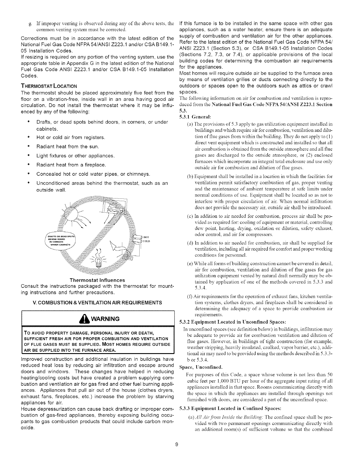
THERMOSTAT LOCATION
The thermostst should be placed approximately five feet from the
floor on a vibration-free, inside wall in an area having good air
circulation. Do net install the thermostat where it may be influ-
enced by any of the following:
* Drafts, or dead spots behind doors, in corners, or under
cabinets.
" Hot or cold air from registers.
* Radiant heat from the sun.
" Light fixtures or other appliances.
• Radiant heat from a fireplace.
" Concealed hot or cold water pipes, or chimneys.
• Unconditioned areas behind the thermostat, such as an
outside wall.
Thermostat Influences
Consult the instructions packaged with the thermostat for mount-
ing instructions and further precautions.
V. COMBUSTION & VENTILATION AiR REQUIREMENTS
WARNING
TO AVOID PROPERTY DAMAGErPERSONAL INJURY OR DEATH_
SUFFICIENT FRESH AIR FOR PROPER COMBUSTION AND VENTILATION
OF FLUE GASES MUST BE SUPPLIED. MOST HOMES REQUIRE OUTSIDE
AIR BE SUPPLIED INTO THE FURNACE AREA.
Improved construction and additional insulation in buildings have
reduced heat loss by reducing air infiltration and escape around
doors and windows. These changes have helped in reducing
heating/cooling costs but have created a problem supplying com-
bustion and ventilation air for gas fired and other fuel burning appli-
ances. Appliances that pull air out of the house (clothes dryers,
exhaust fans, fireplaces, etc.) increase the problem by starving
appliances for air.
House depressurization can cause back drafting or improper com-
bustion of gas-fired appliances, thereby exposing building occu-
pants to gas combustion products that could include carbon mon-
oxide.
If this furnace is to be installed in the same space with other gas
appliances, such as a water heater, ensure there is an adequate
supply of combustion and ventilation air for the other appliances.
Refer to the latest edition of the National Fuel Gas Code NFPA 54/
ANSI Z223.1 (Section 5.3), or CSA B149.1-05 Installation Codes
(Sections 7.2, 7.3, or 7.4), or applicable provisions of the local
building codes for determining the combustion air requirements
for the appliances.
Most homes will require outside air be supplied to the furnace area
by means of ventilation grilles or ducts connecting directly to the
outdoors or spaces open to the outdoors such as attics or crawl
spaces.
The following information on air for combustion and ventilation is repro-
duced fi'om the National Fuel Gas (?ode NFPA 54/ANSI Z223.1 Section
5.3.
5.3.1 General:
(a) The provisions of 5.3 apply to gas utilization equipment installed in
buildings and which require air for combustion, ventilation and dilu-
tion of flue gases fi'om within the building. They do not apply to (1)
direct vent equipment which is constructed and installed so that all
air combustion is obtained from the outside atmosphere and all flue
gases are discharged to the outside atmosphere, or (2) enclosed
fhmaces which incorporate an integral total enclosure and use only
outside air for combustion and dilution of flue gases.
(b) Equipment shall be installed in a location in which the facilities for
ventilation permit satisfactory combustion of gas, proper venting
and the maintenance of ambient temperature at safe limits under
normal conditions of use. Equipment shall be located so as not to
interfere with proper circulation of air. When normal infiltration
does not provide the necessary air, outside air shall be introduced.
(c) In addition to air needed for combustion, process air shall be pro-
vided as required for: cooling of equipment or material, controlling
dew point, heating, &ying, oxidation or dilution, safety exhaust,
odor control, and air for compressors.
(d) In addition to air needed for combustion, air shall be supplied for
ventilation, including all air required for comfort and proper working
conditions for personneh
(e) While all fomas of building constrnction cannot be covered in detail,
air for combustion, ventilation and dilution of flue gases for gas
utilization equipment vented by natural &af_ normally may be ob-
tained by application of one of the methods covered in 5.3.3 and
5.3.4.
(f) Air requirements lbr the operation of exhaust fans, kitchen ventila-
tion systems, clothes &yers, and fireplaces shall be considered in
determining the adequacy of a space to provide combustion air
requirements.
5.3.2 Equipment Located in Unconfined Spaces:
In unconfined spaces (see definition below) in buildings, infiltration may
be adequate to provide air for combustion ventilation and dilution of
flue gases. However, in buildings of tight construction (for example,
weather stripping, heavily insulated, caulked, vapor barrier, etc.), addi-
tional air may need to be provided using the methods described in 5.3.3-
b or 5.3.4.
Space, Unconfined.
For purposes of this Code, a space whose volume is not less than 50
cubic feet per 1,000 BTU per hour of the aggregate input rating of all
appliances installed in that space. Rooms communicating directly with
the space in which the appliances are installed through openings not
furnished with doors, are considered a part of the unconfined space.
5.3.3 Equipment Located in Confined Spaces:
(a) Aft Aicfi'om In._ic]e the BzdMi,g: The confined space shall be pro-
vided with two pemaanent openings communicating directly with
an additional room(s) of sufficient volume so that the combined
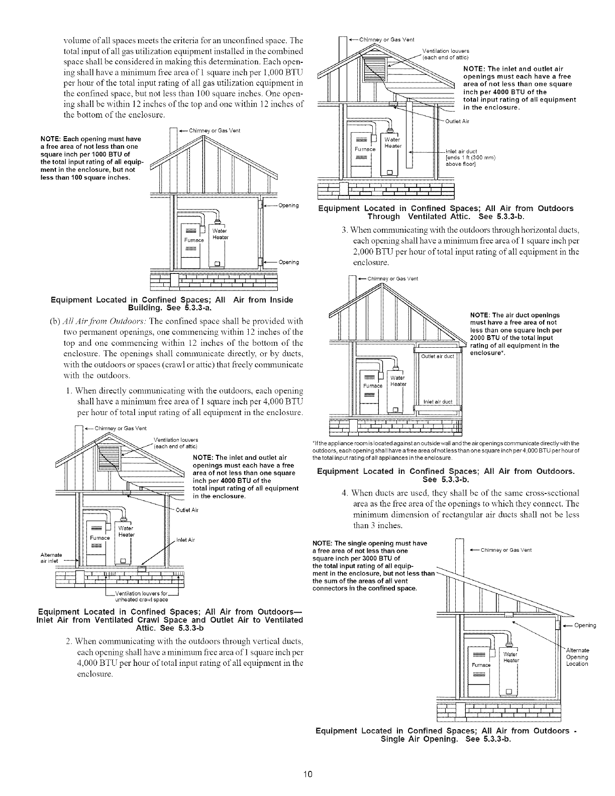
volumeofallspacesmeetsthecriteria%r an unconfined space. The
total input of all gas utilization equipment installed in the combined
space shall be considered in making this determination. Each open-
ing shall have a minimum fi'ee area of I square inch per 1,000 BTU
per hour of the total input rating of all gas utilization equipment in
the confined space, but not less than 100 square inches. One open-
ing shall be within 12 inches of the top and one within 12 inches of
the bottom of the enclosure.
Chimney or Gas Vent
NOTE: Each opening must have
a free area of not tess than one
square inch per 1000 BTU of
the total input rating of all equip-
ment in the enclosure, but not
less than 100 square inches.
_OpeNng
r
Opening
Equipment Located in Confined Spaces; AI! Air from inside
Building. See s.a.a-a.
(b) .4//Ah'fi'om Oz¢Moors: The confined space shall be provided with
two permanent openings, one commencing within 12 inches of the
top and one commencing within 12 inches of the bottom of the
enclosure. The openings shall comnmnicate directly, or by ducts,
with the outdoors or spaces (crawl or attic) that fi'eely communicate
with the outdoors.
l. When directly communicating with the outdoors, each opening
shall have a mininmm free area of 1 square inch per 4,000 BTU
per hour of total input rating of all equipment in the enclosure.
Chimney or Gas Vent
Ventilation louvers
NOTE: The inlet and outlet air
openings must each have a free
area of not tess than one square
inch per 4000 BTU of the
total input rating of all equipment
in the enclosure.
Outlet Air
A_ternate
air inlet
inlet Air
unheated crawl space
Equipment Located in Confined Spaces; AH Air from Outdoors--
Inlet Air from Ventilated Crawl Space and Outlet Air to Ventilated
Attic. See 5.3.3-b
2. When conmmnicating with the outdoors through vertical ducts,
each opening shall have a minimum fi'ee area of 1 square inch per
4,000 BTU per hour of total input rating of all equipment in the
enclosure.
_CNmney or Gas Vent
_fd'l III1_ _% NOTE:Theinletandoutletair
r/ll II Illl_t _ openings must each have a free
IIII II' II '\_ "_-._ area of not less than one square
1111 II II "_l_ inchper4OOOBTUofthe
II I I It It l! "H_ total input rating of all equipment
h_"__.._ __ in the encl°sure.
--Ootlet ,,
Water
Furnace r --tnlet air duct
I a;e I ,end l , OO m,
Equipment Located in Confined Spaces; All Air from Outdoors
Through Ventilated Attic. See 5.3.3-b.
3. When communicating with the outdoors through horizontal ducts,
each opening shall have a mininmm fi'ee area of 1 square inch per
2,000 BTU per hour of total input rating of all equipment in the
enclosure.
l
_-* _J IWater
irnaee I Heater
h ,L
Outlet air duct
fnlet air duct
I I !,, I l,_ t III1
IIf II IfII l IIAI
NOTE: The air duct openings
must have a free area of not
less than one square inch per
2000 BTU of the total input
rating of all equipment in the
enclosure*.
*If the appliance room is located against an outside wall and the air openings comm unicate directly with the
outdoors, each opening sh all have a free a rea of not less than one sq ua re inch per 4.000 BTU per hou r of
the total input rating of all appliances in the enclosure
Equipment Located in Confined Spaces; All Air from Outdoors.
See 5.3.3-b.
4. When ducts are used, they shall be of the same cross-sectional
area as the fi'ee area of the openings to which they connect. The
minimum dimension of rectangular air ducts shall not be less
than 3 inches.
NOTE: The single opening must have
a free area of not less than one
square inch per 3000 BTU of
the total input rating of all equip-
ment in the enclosure
the sum of the areas of all vent
connectors in the confined space.
Chimney or Gas Vent
__ _ Opening
I "Alternate
Opening
Location
_ tl iI tl 11 ,IiI it ,I
p f I
Equipment Located in Confined Spaces; All Air from Outdoors -
Single Air Opening. See 5.&3-b.
10
5. When directly communicating with the outdoors, the single open-
ing shall have a minimum fi'ee area of 1 square inch per 3,000
BTU per hour of total input rating of all equipment in the enclo-
sure.
5.3.4 Specially Engineered Installations:
The requirements of 5.3.3 shall not necessarily govern when special engi-
neering, approved by the authority having jurisdiction, provides an
adequate supply of air fbr combustion, ventilation, and dilution of flue
gases.
5.3.5 Louvers and Grilles:
In calculating fi'ee area in 5.3.3, consideration shall be given to the blocking
effect of louvers, grilles or screens protecting openings. Screens used
shall not be smaller than 1/4 inch mesh. If the area through a design of
louver or grille is known, it should be used in calculating the size of
opening required to provide the fi'ee area specified. If the design and fi'ee
area is not known, it may be assumed that wood louvers will have 20-25
percent free area and metal louvers and grilles will have 60-75 percent
fi'ee area. Louvers and grilles shall be fixed in the open position or
interlocked with the equipment so that they are opened automatically
during equipment operation.
5.3.6 Special Conditions Created by Mechanical Exhausting or Fire-
places:
Operation of exhaust fans, ventilation systems, clothes dryers, or fireplaces
may create conditions requiring special attention to avoid unsatisfac-
tory operation of installed gas utilization equipment. Air from Inside
Building. See 5.3.3-a.
Vi. INSTALLATION POSITIONS
This furnace may be installed in an upright position or horizontal
on either the left or right side panel. Do not install this furnace on
its back. For upright upflow furnaces, return air ductwork may be
attached to the side panel(s) and/or basepan. For horizontal up-
flow furnaces, return air ductwork must be attached to the basepan.
For both upright or horizontal counterflow furnaces, return duct-
work must be attached to the basepan (top end of the blower com-
partment). NOTE: Ductwork must never be attached to the back of
the furnace. Contact your distributor for proper airflow require-
ments and number of required ductwork connections. Refer to
"Recommended Installation Positions" figure for appropriate in-
stallation positions, ductwork connections, and resulting airflow
arrangements.
VII. HORIZONTAL APPLICATIONS &CONSIDERATIONS
GENERAL
Horizontal applications, in particular, may dictate many of the
installation's specifics such as airflow direction, ductwork connec-
tions, flue and combustion air pipe connections, etc. The basic
application of this furnace as a horizontal furnace differs only slightly
from an upright installation. When installing a furnace horizontally,
additional consideration must be given to the following:
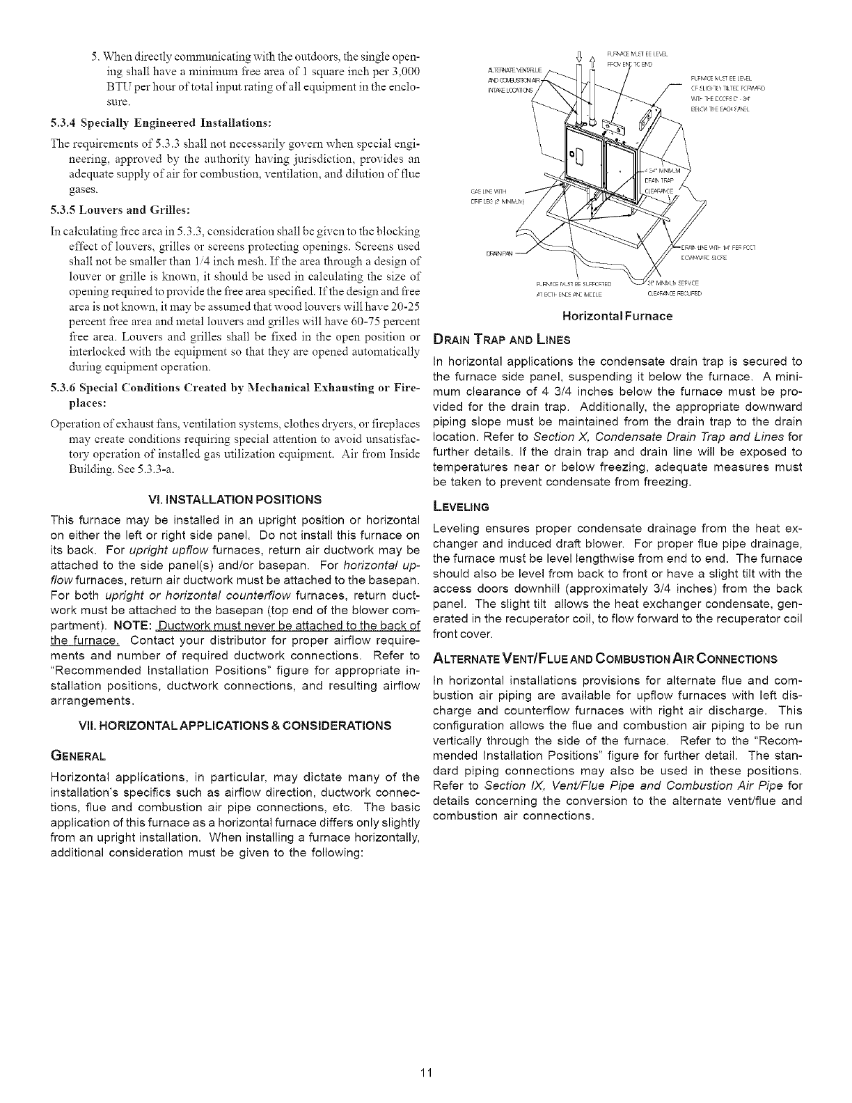
,_] Eqk ENEE ,@,E MEELE CLE?F,_I_CE BECUBED
Horizontal Furnace
DRAIN TRAP AN[) LINES
In horizontal applications the condensate drain trap is secured to
the furnace side panel, suspending it below the furnace. A mini-
mum clearance of 4 3/4 inches below the furnace must be pro-
vided for the drain trap. Additionally, the appropriate downward
piping slope must be maintained from the drain trap to the drain
location. Refer to Section X, Condensate Drain Trap and Lines for
further details. If the drain trap and drain line will be exposed to
temperatures near or below freezing, adequate measures must
be taken to prevent condensate from freezing.
LEVELING
Leveling ensures proper condensate drainage from the heat ex-
changer and induced draft blower. For proper flue pipe drainage,
the furnace must be level lengthwise from end to end. The furnace
should also be level from back to front or have a slight tilt with the
access doors downhill (approximately 3/4 inches) from the back
panel. The slight tilt allows the heat exchanger condensate, gen-
erated in the recuperator coil, to flow forward to the recuperator coil
front cover.
ALTERNATE VENT/FLUE AND COMBUSTION AIR CONNECTIONS
In horizontal installations provisions for alternate flue and com-
bustion air piping are available for upflow furnaces with left dis-
charge and counterflow furnaces with right air discharge. This
configuration allows the flue and combustion air piping to be run
vertically through the side of the furnace. Refer to the "Recom-
mended Installation Positions" figure for further detail. The stan-
dard piping connections may also be used in these positions.
Refer to Section IX, Vent/Flue Pipe and Combustion Air Pipe for
details concerning the conversion to the alternate vent/flue and
combustion air connections.
11
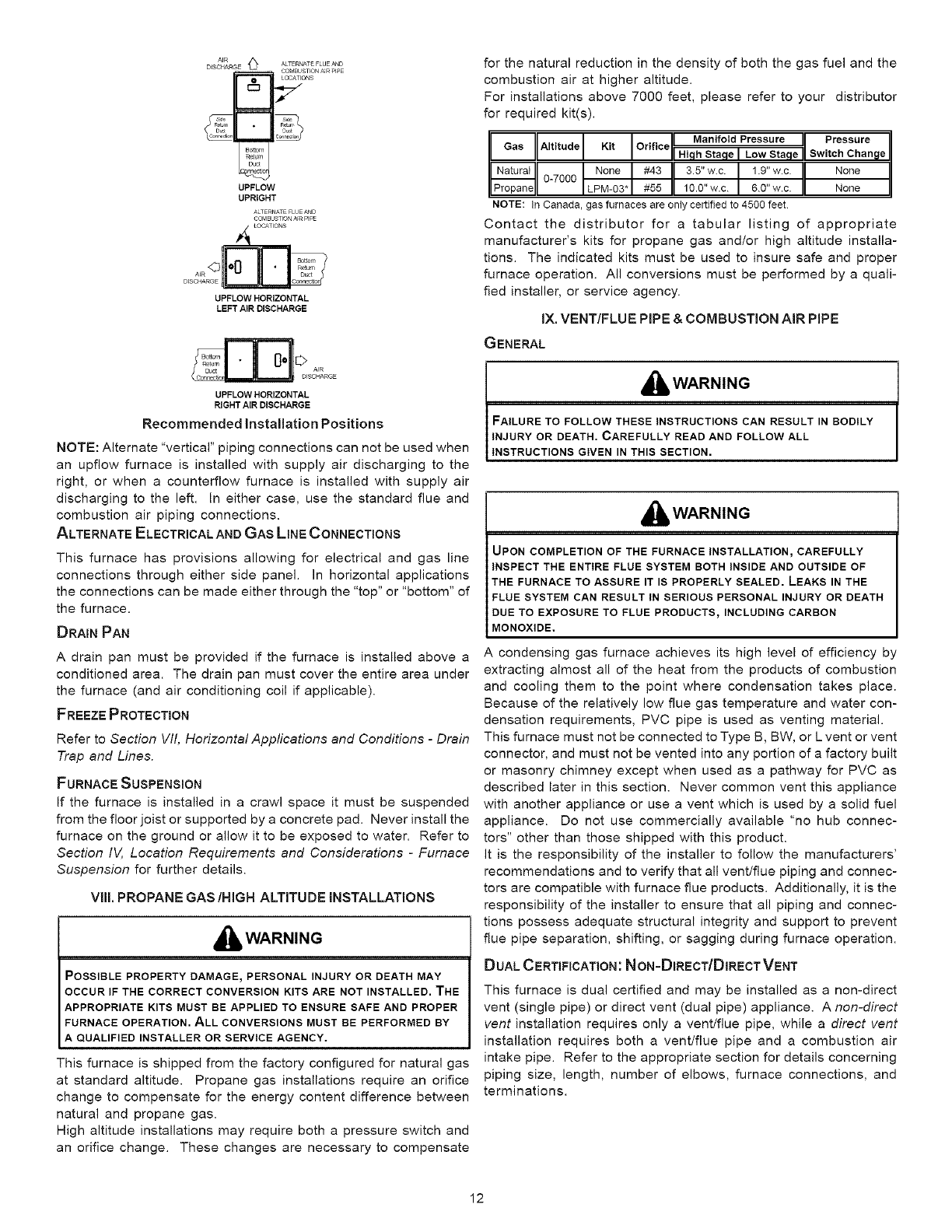
A,R t_}
D_SOHARGE ALTERNATEFLUEAND
UPFLOW
UPRIGHT
ALTERNATE FLUE AND
COMBUSTION A[_ PIPE
LOCATIONS
A_R Durt
DISCHARGE _
UPFLOW HORIZONTAL
LEFT AIR DISCHARGE
_[_ AIR
D_SC_ARGE
UPFLOW HORIZONTAL
RIGHT AIR DISCHARGE
Recommended Installation Positions
NOTE: Alternate "vertical" piping connections can not be used when
an upflow furnace is installed with supply air discharging to the
right, or when a counterflow furnace is installed with supply air
discharging to the left. In either case, use the standard flue and
combustion air piping connections.
ALTERNATE ELECTRICAL AND GAS LINE CONNECTIONS
This furnace has provisions allowing for electrical and gas line
connections through either side panel. In horizontal applications
the connections can be made either through the "top" or "bottom" of
the furnace.
DRAIN PAN
A drain pan must be provided if the furnace is installed above a
conditioned area. The drain pan must cover the entire area under
the furnace (and air conditioning coil if applicable).
FREEZE PROTECTION
Refer to Section VII, Horizontal Appfications and Conditions -Drain
Trap and Lines.
FURNACE SUSPENSION
If the furnace is installed in a crawl space it must be suspended
from the floor joist or supported by a concrete pad. Never install the
furnace on the ground or allow it to be exposed to water. Refer to
Section IV, Location Requirements and Considerations -Furnace
Suspension for further details.
VIII, PROPANE GAS/HIGH ALTITUDE INSTALLATIONS
_i, WARNING
POSSIBLE PROPERTY DAMAGE, PERSONAL INJURY OR DEATH MAY
OCCUR iF THE CORRECT CONVERSION KITS ARE NOT INSTALLED. THE
APPROPRIATE KITS MUST BE APPLIED TO ENSURE SAFE AND PROPER
FURNACE OPERATION. ALL CONVERSIONS MUST BE PERFORMED BY
A QUALIFIED INSTALLER OR SERVICE AGENCY.
This furnace is shipped from the factory configured for natural gas
at standard altitude. Propane gas installations require an orifice
change to compensate for the energy content difference between
natural and propane gas.
High altitude installations may require both a pressure switch and
an orifice change. These changes are necessary to compensate
for the natural reduction in the density of both the gas fuel and the
combustion air at higher altitude.
For installations above 7000 feet, please refer to your distributor
for required kit(s).
iII Manifold Pressure II Pressure li
Gas Altitude Kit Orifice , = .
II I_ Hi h Sta e Low Sta e _1
o_7ooo 13.5,,w.c. 1,.9,,w.c.1l None
_Propanell ILPM-93*J#55 II 10.0"w.c./ 6.0"w.c./I None IJ
NOTE: In Canada,gas furnaces are onlycertifiedto 4500 feet.
Contact the distributor for a tabular listing of appropriate
manufacturer's kits for propane gas and/or high altitude installa-
tions. The indicated kits must be used to insure safe and proper
furnace operation. All conversions must be performed by a quali-
fied installer, or service agency.
IX. VENT/FLUE PiPE & COMBUSTION AIR PiPE
GENERAL
I_WARNING
FAILURE TO FOLLOW THESE INSTRUCTIONS CAN RESULT IN BODILY
INJURY OR DEATH. CAREFULLY READ AND FOLLOW ALL
INSTRUCTIONS GIVEN IN THIS SECTION.
I_WARNING
UPON COMPLETION OF THE FURNACE INSTALLATION, CAREFULLY
INSPECT THE ENTIRE FLUE SYSTEM BOTH INSIDE AND OUTSIDE OF
THE FURNACE TO ASSURE IT IS PROPERLY SEALED. LEAKS IN THE
FLUE SYSTEM CAN RESULT iN SERIOUS PERSONAL INJURY OR DEATH
DUE TO EXPOSURE TO FLUE PRODUCTS, INCLUDING CARBON
MONOXIDE.
A condensing gas furnace achieves its high level of efficiency by
extracting almost all of the heat from the products of combustion
and cooling them to the point where condensation takes place.
Because of the relatively low flue gas temperature and water con-
densation requirements, PVC pipe is used as venting material.
This furnace must not be connected to Type B, BW, or L vent or vent
connector, and must not be vented into any portion of a factory built
or masonry chimney except when used as a pathway for PVC as
described later in this section. Never common vent this appliance
with another appliance or use a vent which is used by a solid fuel
appliance. Do not use commercially available "no hub connec-
tors" other than those shipped with this product.
It is the responsibility of the installer to follow the manufacturers'
recommendations and to verify that all vent/flue piping and connec-
tors are compatible with furnace flue products. Additionally, it is the
responsibility of the installer to ensure that all piping and connec-
tions possess adequate structural integrity and support to prevent
flue pipe separation, shifting, or sagging during furnace operation.
DUAL CERTIFICATION: N oN=DERECTIDIRECT VENT
This furnace is dual certified and may be installed as a non-direct
vent (single pipe) or direct vent (dual pipe) appliance. A non-direct
vent installation requires only a vent/flue pipe, while a direct vent
installation requires both a vent/flue pipe and a combustion air
intake pipe. Refer to the appropriate section for details concerning
piping size, length, number of elbows, furnace connections, and
terminations.
12
MATERIALS AND JOINING M ETNODS
,_ WARNING
TO AVOID BODILY INJURY, FIRE OR EXPLOSION, SOLVENT CEMENTS
MUST BE KEPT AWAY FROM ALL IGNITION SOURCES (I.E._ SPARKS,
OPEN FLAMES_ AND EXCESSIVE HEAT) AS THEY ARE COMBUSTIBLE
LIQUIDS. AVOID BREATHING CEMENT VAPORS OR CONTACT WITH
SKIN AND/OR EYES.
Two- or three-inch nominal diameter PVC Schedule 40 pipe meet-
ing ASTM D1785, PVC primer meeting ASTM F656, and PVC sol-
vent cement meeting ASTM D2564 specifications must be used.
Fittings must be DWV type fittings meeting ASTM D2665 and ASTM
D3311. Carefully follow the pipe manufacturer's instructions for
cutting, cleaning, and solvent cementing of PVC.
As an alternative to PVC pipe, primer, solvent cement, and fittings,
ABS materials which are in compliance with the following specifi-
cations may be used. Two-or-three-inch ABS Schedule 40 pipe
must meet ASTM D1527 and, if used in Canada, must be CSA
listed. Solvent cement for ABS to ABS joints must meet ASTM
D2235 and, if used in Canada, must be CSA listed. The solvent
cement for the PVC to ABS transition joint must meet ASTM D3138.
Fittings must be DWV type fittings meeting ASTM D2661 and ASTM
D3311 and, if used in Canada, must be CSA listed. Carefully
follow the manufacturers' instructions for cutting, cleaning, and
solvent cementing PVC and/or ABS.
All 90 ° elbows must be medium radius (1/4 bend DWV) or long
radius (Long sweep 1/4 bend DWV) types conforming to ASTM
D3311. A medium radius (1/4 bend DWV) elbow measures 3 1/
16" minimum from the plane of one opening to the centerline of the
other opening for 2" diameter pipe, and 4 9/16" minimum for 3"
pipe.
PROPER VENT/FLUE AND COMBUSTION AIR PIPING PRACTICES
Adhere to these instructions to ensure safe and proper furnace
performance. The length, diameter, and number of elbows of the
vent/flue pipe and combustion air pipe (when applicable) affects
the performance of the furnace and must be carefully sized. All
piping must be installed in accordance with local codes and these
instructions.
Piping must be adequately secured and supported to prohibit sag-
ging, joint separation, and/or detachment from the furnace. Hori-
zontal runs of vent/flue piping must be supported every three to five
feet and must maintain a 1/4 inch per foot downward slope, back
towards the furnace, to properly return condensate to the furnace's
drain system. Allowances should be made for minor expansion
and contraction due to temperature variations. For this reason,
particular care must be taken to secure piping when a long run is
followed by a short offset of less than 40 inches.
Precautions should be taken to prevent condensate from freezing
inside the vent/flue pipe and/or at the vent/flue pipe termination. All
vent/flue piping exposed to freezing temperatures below 35°F for
extended periods of time must be insulated with 1/2" thick closed
cell foam. Also all vent/flue piping exposed outdoors in excess of
the terminations shown in this manual (or in unheated areas)
must be insulated with 112" thick closed cell foam. Inspect piping
for leaks prior to installing insulation.
TERMINATION LOCATIONS
NOTES: Refer to Section IV, Location Requirements and
Considerations for combustion air contaminant restrictions.
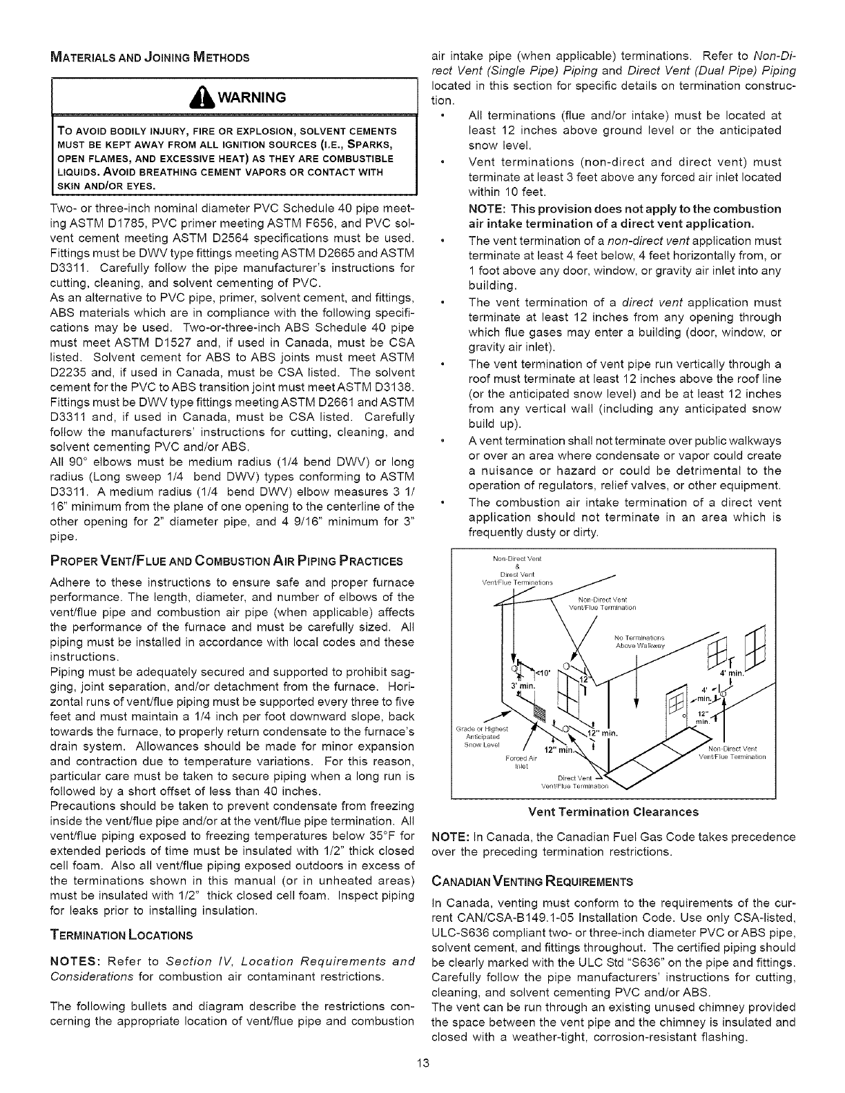
The following bullets and diagram describe the restrictions con-
cerning the appropriate location of vent/flue pipe and combustion
air intake pipe (when applicable) terminations. Refer to Non-Di-
rect Vent (Single Pipe) Piping and Direct Vent (Dual Pipe) Piping
located in this section for specific details on termination construc-
tion.
All terminations (flue andtor intake) must be located at
least 12 inches above ground level or the anticipated
snow level.
Vent terminations (non-direct and direct vent) must
terminate at least 3 feet above any forced air inlet located
within 10 feet.
NOTE: This provision does not apply to the combustion
air intake termination of a direct vent application.
The vent termination of a non-direct vent application must
terminate at least 4 feet below, 4 feet horizontally from, or
1 foot above any door, window, or gravity air inlet into any
building.
The vent termination of a direct vent application must
terminate at least 12 inches from any opening through
which flue gases may enter a building (door, window, or
gravity air inlet).
The vent termination of vent pipe run vertically through a
roof must terminate at least 12 inches above the roof line
(or the anticipated snow level) and be at least 12 inches
from any vertical wall (including any anticipated snow
build up).
A vent termination shall not terminate over public walkways
or over an area where condensate or vapor could create
a nuisance or hazard or could be detrimental to the
operation of regulators, relief valves, or other equipment.
The combustion air intake termination of a direct vent
application should not terminate in an area which is
frequently dusty or dirty.
Non Direct Vent
&
Grade or Highest
Anticipated
Vent Termination Clearances
NOTE: In Canada, the Canadian Fuel Gas Code takes precedence
over the preceding termination restrictions.
CANADIAN VENTING REQUIREMENTS
In Canada, venting must conform to the requirements of the cur-
rent CAN/CSA-B149.1-05 Installation Code. Use only CSA-listed,
ULC-S636 compliant two- or three-inch diameter PVC crABS pipe,
solvent cement, and fittings throughout. The certified piping should
be clearly marked with the ULC Std "S636" on the pipe and fittings.
Carefully follow the pipe manufacturers' instructions for cutting,
cleaning, and solvent cementing PVC and/or ABS.
The vent can be run through an existing unused chimney provided
the space between the vent pipe and the chimney is insulated and
closed with a weather-tight, corrosion-resistant flashing.
13
STANDARD FURNACE CONNECTIONS
It is the responsibility of the installer to ensure that the piping
connections to the furnace are secure, airtight, and adequately
supported.
As shipped, attachment "couplings" for vent/flue and combustion
air intake pipe connections are provided on the furnace's top cover
(upflow) or basepan (counterflow). To use the standard connec-
tions, field supplied vent/flue pipe and combustion air intake pipe
(when applicable) should be secured directly to the furnace at
these locations.
VENT/FLuEPIpE
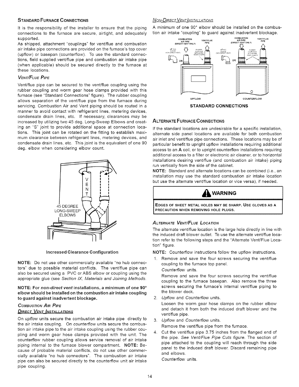
Vent/flue pipe can be secured to the vent/flue coupling using the
rubber coupling and worm gear hose clamps provided with this
furnace (see "Standard Connections" figure). The rubber coupling
allows separation of the vent/flue pipe from the furnace during
servicing. Combustion Air and Vent piping should be routed in a
manner to avoid contact with refrigerant lines, metering devices,
condensate drain lines, etc. if necessary, clearances may be
increased by utilizing two 45 deg. Long-Sweep Elbows and creat-
ing an "S" joint to provide additional space at connection loca-
tions. This joint can be rotated on the fitting to establish maxi-
mum clearance between refrigerant lines, metering devices, and
condensate drain lines, etc. This joint is the equivalent of one 90
deg. elbow when considering elbow count.
increased Clearance Configuration
NOTE: Do not use other commercially available "no hub connec-
tors" due to possible material conflicts. The vent/flue pipe can
also be secured using a PVC or ABS elbow or coupling using the
appropriate glue (see Section IX, Materials and Joining Methods.
NOTE: For non-direct vent installations, a minimum of one 90 °
elbow should be installed on the combustion air intake coupling
to guard against inadvertent blockage.
COMBUSTIONAIR PIPE
On upflow units secure the combustion air intake pipe directly to
the air intake coupling. On counterflow units secure the combus-
tion air intake pipe to the air intake coupling using the rubber cou-
pling and worm gear hose clamps provided with the unit. The
counterflow rubber coupling allows service removal of air intake
piping internal to the furnace blower compartment. NOTE: Be-
cause of probable material conflicts, do not use other commer-
cially available "no hub connectors". The combustion air intake
pipe can also be secured directly to the counterflow unit air intake
pipe coupling.
NoN-DIRECT VENT INS TALLATtONS
A minimum of one 90 ° elbow should be installed on the combus-
tion air intake "coupling" to guard against inadvertent blockage.
COMSUST_ON
AIR PIPE VENT/FLUE
(DIRECT VENT ONLY) PIPE
UPFLOW
COMBUSTION VENT/FLUE
A_RPIPE P_PE
(DIRECT VENT ONLY)
!F "_
oR
COUNTERFLOW
STANDARD CONNECTIONS
ALTERNATE FURNACE CONNECTIONS
If the standard locations are undesirable for a specific installation,
alternate side panel locations are available for both combustion
air inlet and vent/flue pipe connections. These locations may be of
particular benefit to upright upflow installations requiring additional
access to an A coil, or to upright counterflow installations requiring
additional access to a filter or electronic air cleaner, or to horizontal
installations desiring vent/flue (and combustion air intake) piping
run vertically from the side of the cabinet.
NOTE: Standard and alternate locations can be combined (i.e., an
installation may use the standard combustion air intake location
but use the alternate vent/flue location or vice versa), if needed.
,_ WARNING
EDGES OF SHEET METAL HOLES MAY BE SHARP. USE GLOVES AS A
PRECAUTION WHEN REMOVING HOLE PLUGS.
ALTERNATE VENT/FLuE LOCATION
The alternate vent/flue location is the large hole directly in line with
the induced draft blower outlet. To use the alternate vent/flue loca-
tion refer to the following steps and the "Alternate Vent/Flue Loca-
tion" figure.
NOTE: Counterflow instructions follow the upfiow instructions.
1. Remove and save the four screws securing the vent/flue
coupling to the furnace top panel.
Counterflow units.
Remove and save the four screws securing the vent/flue
coupling to the furnace basepan. Also remove the three
screws securing the furnace's internal vent/flue piping to
the blower deck.
2. Upflow and Counterflow units.
Loosen the worm gear hose clamps on the rubber elbow
and detach it from both the induced draft blower and the
vent/flue pipe.
3. Upflow and Counterflow units.
Remove the vent/flue pipe from the furnace.
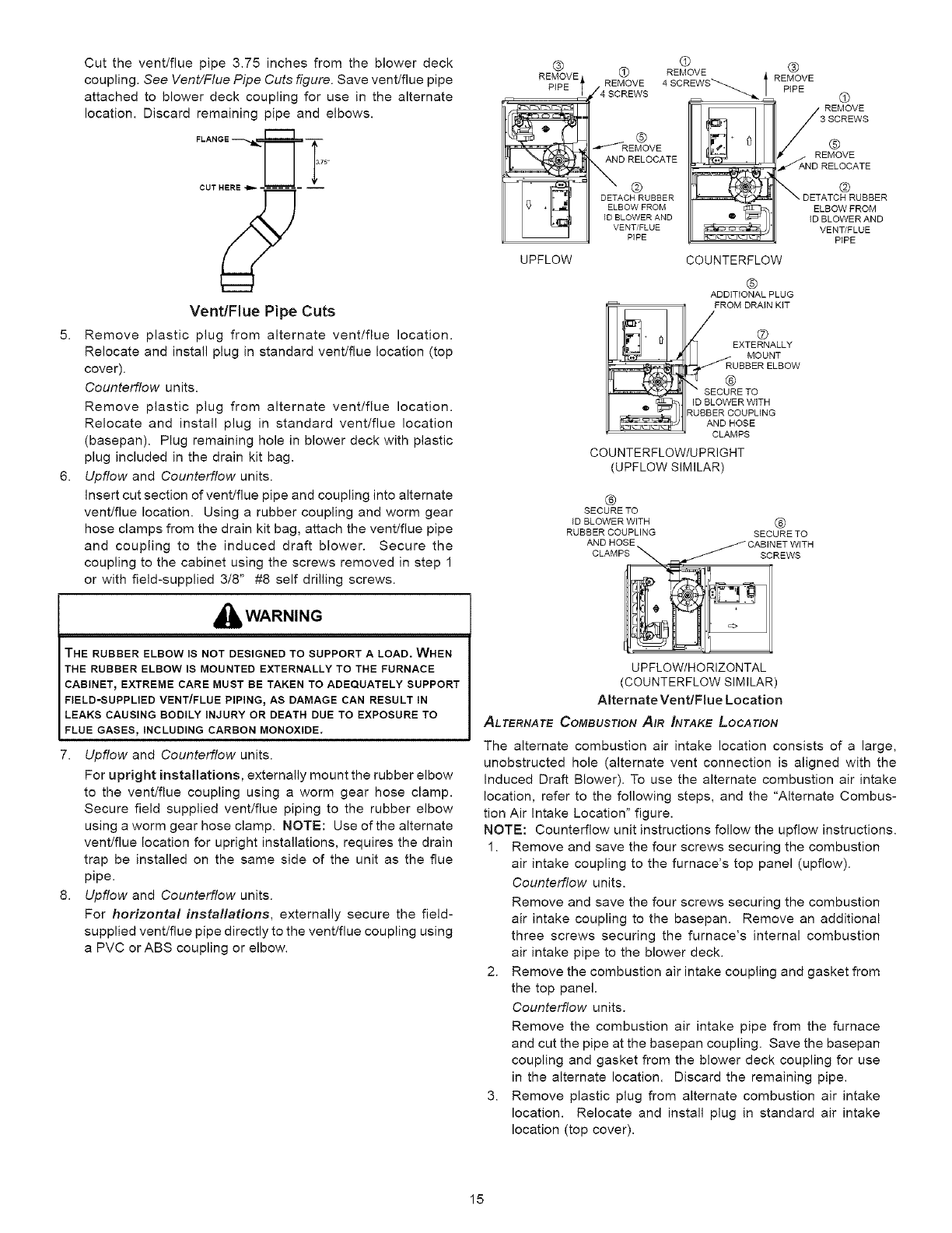
4. Cut the vent/flue pipe 3.75 inches from the flanged end of
the pipe. See Vent/Flue Pipe Cuts figure. The section of
pipe attached to the coupling will reach through the side
panel to the induced draft blower. Discard remaining pipe
and elbows.
Counterflow units.
14
5.
6.
Cut the vent/flue pipe 3.75 inches from the blower deck
coupling. See Vent/Flue Pipe Cuts figure. Save vent/flue pipe
attached to blower deck coupling for use in the alternate
location. Discard remaining pipe and elbows.
CUT _- --
Vent/Flue Pipe Cuts
Remove plastic plug from alternate vent/flue location.
Relocate and install plug in standard vent/flue location (top
cover).
Counterflow units.
Remove plastic plug from alternate vent/flue location.
Relocate and install plug in standard vent/flue location
(basepan). Plug remaining hole in blower deck with plastic
plug included in the drain kit bag.
Upflow and Counterflow units.
Insert cut section of vent/flue pipe and coupling into alternate
vent/flue location. Using a rubber coupling and worm gear
hose clamps from the drain kit bag, attach the vent/flue pipe
and coupling to the induced draft blower. Secure the
coupling to the cabinet using the screws removed in step 1
or with field-supplied 3/8" #8 self drilling screws.
_lb WARNING
THE RUBBER ELBOW IS NOT DESIGNED TO SUPPORT A LOAD. WHEN
THE RUBBER ELBOW IS MOUNTED EXTERNALLY TO THE FURNACE
CABINET_ EXTREME CARE MUST BE TAKEN TO ADEQUATELY SUPPORT
FIELD-SUPPLIED VENT/FLUE PIPING_ AS DAMAGE CAN RESULT IN
LEAKS CAUSING BODILY INJURY OR DEATH DUE TO EXPOSURE TO
FLUE GASES, INCLUDING CARBON MONOXIDE.
7. Upflow and Counterflow units.
For upright installations, externally mount the rubber elbow
to the vent/flue coupling using a worm gear hose clamp.
Secure field supplied vent/flue piping to the rubber elbow
using a worm gear hose clamp. NOTE: Use of the alternate
vent/flue location for upright installations, requires the drain
trap be installed on the same side of the unit as the flue
pipe.
8. Upflow and Counterflow units.
For horizontal installations, externally secure the field-
supplied vent/flue pipe directly to the vent/flue coupling using
a PVC or ABS coupling or elbow.
®
%eVEt
-__
UPFLOW
© ®
REMOVE
REMOVE 4SCREWS REMOVE
/4 SCREWS _ PIPE
__/ REMOVE
3 SCREWS
®
d_/_'REMOVE @
_ _ REMOVE
D RELOCATE
._ AND RELOCATE
DETACH RUBBER _f_
ELBOW FROM
ID BLOWER AND
VENT/FLUE
PIPE
COUNTERFLOW
@
DETATCH RUBBER
ELBOW FROM
ID BLOWER AND
VENT/FLUE
PIPE
,"ql • _1
®
ADDITIONAL PLUG
FROM DRAIN KiT
LEXTERNALLY
MOUNT
RUBBER ELBOW
SECURE TO
ID BLOWER WITH
_UBBER COUPLING
AND HOSE
CLAMPS
COUNTERFLOW/UPRIGHT
(UPFLOW SIMILAR)
®
SECURE TO
ID BLOWER WITH ®
RUBBER COUPLING SECURE TO
AND HOSE
UPFLOW/HORIZONTAL
(COUNTERFLOW SIMILAR)
Alternate Vent/Flue Location
ALTERNATE COMBUSTION AIR _NTAKE LOCATION
The alternate combustion air intake location consists of a large,
unobstructed hole (alternate vent connection is aligned with the
Induced Draft Blower). To use the alternate combustion air intake
location, refer to the following steps, and the "Alternate Combus-
tion Air Intake Location" figure.
NOTE: Counterflow unit instructions follow the upfiow instructions.
1. Remove and save the four screws securing the combustion
air intake coupling to the furnace's top panel (upflow).
Counterflow units.
Remove and save the four screws securing the combustion
air intake coupling to the basepan. Remove an additional
three screws securing the furnace's internal combustion
air intake pipe to the blower deck.
2. Remove the combustion air intake coupling and gasket from
the top panel.
Counterflow units.
Remove the combustion air intake pipe from the furnace
and cut the pipe at the basepan coupling. Save the basepan
coupling and gasket from the blower deck coupling for use
in the alternate location. Discard the remaining pipe.
3. Remove plastic plug from alternate combustion air intake
location. Relocate and install plug in standard air intake
location (top cover).
15
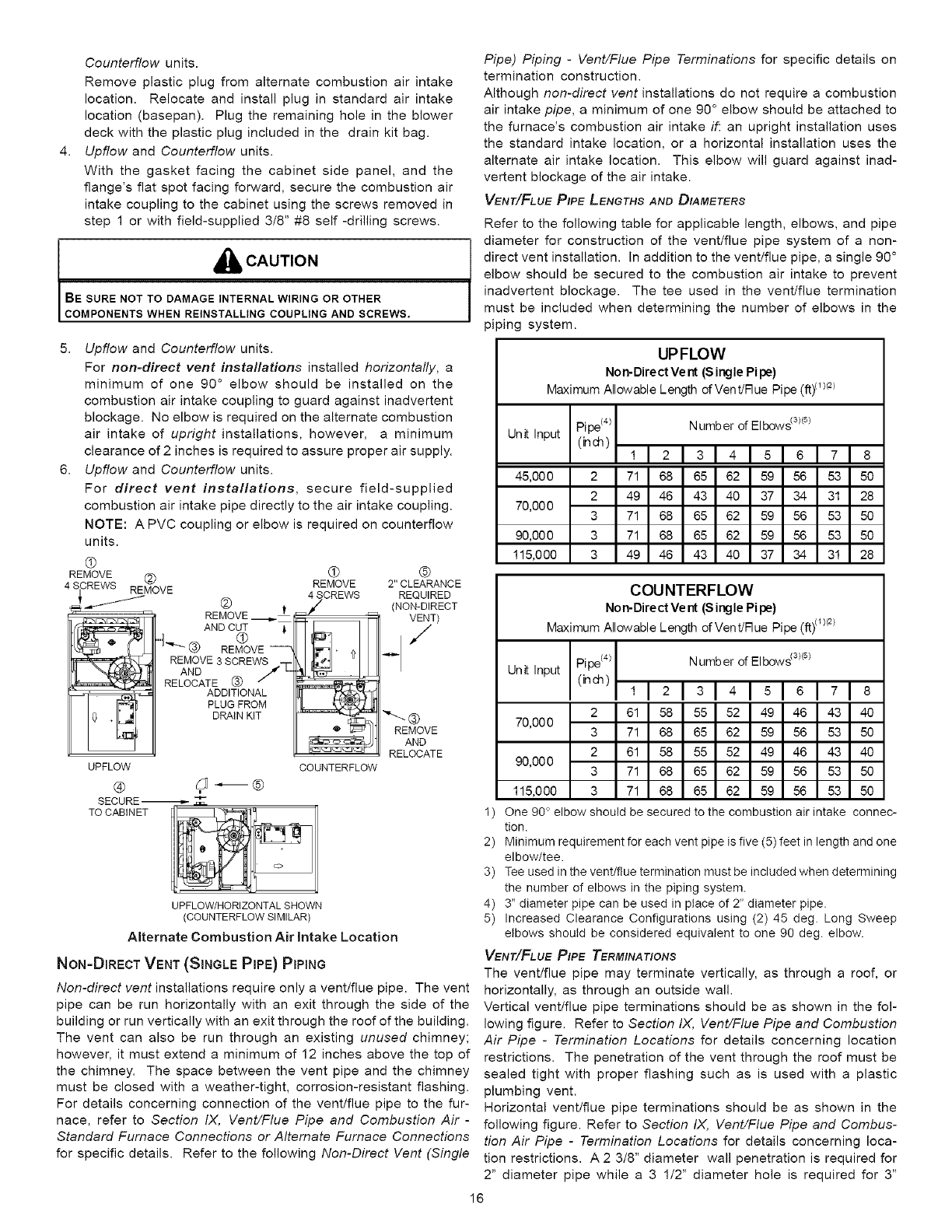
4.
Counterflow units.
Remove plastic plug from alternate combustion air intake
location. Relocate and install plug in standard air intake
location (basepan). Plug the remaining hole in the blower
deck with the plastic plug included in the drain kit bag.
Upflew and Counterflew units.
With the gasket facing the cabinet side panel, and the
flange's flat spot facing forward, secure the combustion air
intake coupling to the cabinet using the screws removed in
step 1 or with field-supplied 3/8" #8 self -drilling screws.
_h, CAUTION
BE SURE NOT TO DAMAGE INTERNAL WIRING OR OTHER
COMPONENTS WHEN REINSTALLING COUPLING AND SCREWS.
Pipe) Piping -Vent/Flue Pipe Terminations for specific details on
termination construction.
Although non-direct vent installations do not require a combustion
air intake pipe, a minimum of one 90 ° elbow should be attached to
the furnace's combustion air intake if: an upright installation uses
the standard intake location, or a horizontal installation uses the
alternate air intake location. This elbow will guard against inad-
vertent blockage of the air intake.
VENT/FLuE PIPE LENGTHS AND DIAMETERS
Refer to the following table for applicable length, elbows, and pipe
diameter for construction of the vent/flue pipe system of a non-
direct vent installation. In addition to the vent/flue pipe, a single 90 °
elbow should be secured to the combustion air intake to prevent
inadvertent blockage. The tee used in the vent/flue termination
must be included when determining the number of elbows in the
piping system.
5. Upflew and Counterflew units.
For non-direct vent installations installed horizontally, a
minimum of one 90 ° elbow should be installed on the
combustion air intake coupling to guard against inadvertent
blockage. No elbow is required on the alternate combustion
air intake of upright installations, however, a minimum
clearance of 2 inches is required to assure proper air supply.
6. Upflow and Counterflow units.
For direct vent installations, secure field-supplied
combustion air intake pipe directly to the air intake coupling.
NOTE: A PVC coupling or elbow is required on counterflow
units.
®
REMOVE _)
4 S 3REWS REMOVE
Q ®
REMOVE 2" CLEARANCE
JCREWS REQUIRED
@ -_ t (NON-DIRECT
REMOVE = _ VENT)
,/
AND CUT
4-.-_.® ©
REMOVE --
REMOVE 3 SCREWS
AND /.4 L.
RELOCATE ® /
ADDITIONAL
PLUGFROM
DRAINKIT
UPFLOW
®
SECURE-_
TO CABINET
COUNTERFLOW
""- ®
REMOVE
AND
RELOCATE
UPFLOW/HORIZONTAL SHOWN
(COUNTERFLOW SIMILAR)
Alternate Combustion Air Intake Location
NoN-DIRECT VENT (SINGLE PIPE} PiPiNG
Non-direct vent installations require only a vent/flue pipe. The vent
pipe can be run horizontally with an exit through the side of the
building or run vertically with an exit through the roof of the building.
The vent can also be run through an existing unused chimney;
however, it must extend a minimum of 12 inches above the top of
the chimney. The space between the vent pipe and the chimney
must be closed with a weather-tight, corrosion-resistant flashing.
For details concerning connection of the vent/flue pipe to the fur-
nace, refer to Section IX, Vent/Flue Pipe and Combustion Air -
Standard Furnace Connections or Alternate Furnace Connections
for specific details. Refer to the following Non-Direct Vent (Single
UPFLOW
Non-Direct Vent (S ingle Pipe)
Maximum Allowable Length of Vent/Rue Pipe (ft)(1/(2)
Pipe(4) Numb er of Elbows(3)(_)
Unit Input (inch) 1121al4151 1718
45,00 0 2 71 68 65 62 59 56 53 50
2 49 46 43 40 37 34 31 28
70,00 0 3 71 68 65 62 59 56 53 50
90,00 0 3 71 68 65 62 59 56 53 50
115,000 3 49 46 43 40 37 34 31 28
COUNTERFLOW
Non-Direct Ve nt (S ingle Pipe)
Maximum Allowable Length of Vent/Rue Pipe (ft)(1)(2)
Unitlnput Pipe(4) Numb er of Elbow_ 3/(_)
(inch) 1 2 3 4 5 6 7 8
2 61 58 55 52 49 46 43 40
70,000 3 71 68 65 62 59 56 53 50
2 61 58 55 52 49 46 43 40
90,000 3 71 68 65 62 59 56 53 50
115,000 3 71 68 65 62 59 56 53 50
I ) One 90 ° elbow should be secured to the combustion air intake connec-
tion.
2) Minimum requirement for each vent pipe is five (5) feet in length and one
elbow/tee.
3) Tee used in the vent/flue termination must be included when determining
the number of elbows in the piping system.
4) 3" diameter pipe can be used in place of 2" diameter pipe.
5) Increased Clearance Configurations using (2) 45 deg. Long Sweep
elbows should be considered equivalent to one 90 deg. elbow.
VENT/FLuEPIpE TERMINATIONS
The vent/flue pipe may terminate vertically, as through a roof, or
horizontally, as through an outside wall.
Vertical vent/flue pipe terminations should be as shown in the fol-
lowing figure. Refer to Section IX, Vent/Flue Pipe and Combustion
Air Pipe -Termination Locations for details concerning location
restrictions. The penetration of the vent through the roof must be
sealed tight with proper flashing such as is used with a plastic
plumbing vent.
Horizontal vent/flue pipe terminations should be as shown in the
following figure. Refer to Section IX, Vent/Flue Pipe and Combus-
tion Air Pipe -Termination Locations for details concerning loca-
tion restrictions. A 2 3/8" diameter wall penetration is required for
2" diameter pipe while a 3 1/2" diameter hole is required for 3"
16
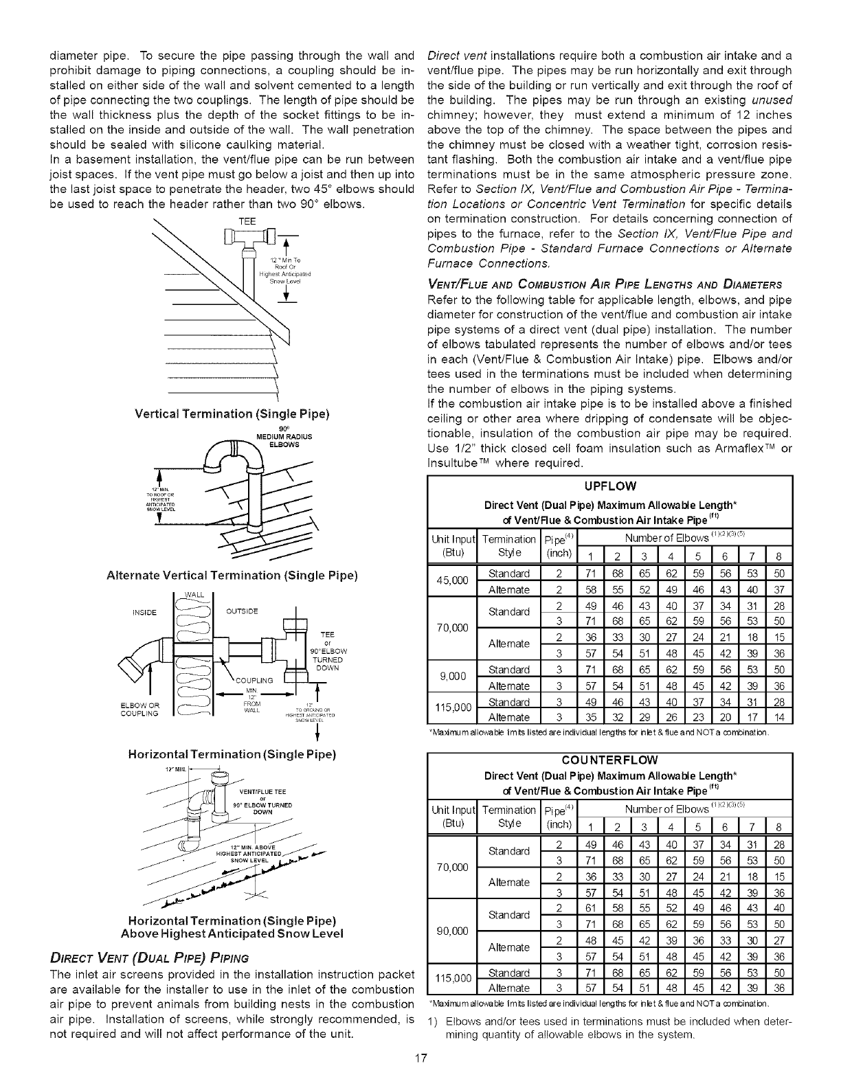
diameter pipe. To secure the pipe passing through the wall and
prohibit damage to piping connections, a coupling should be in-
stalled on either side of the wall and solvent cemented to a length
of pipe connecting the two couplings. The length of pipe should be
the wall thickness plus the depth of the socket fittings to be in-
stalled on the inside and outside of the wall. The wall penetration
should be sealed with silicone caulking material.
In a basement installation, the vent/flue pipe can be run between
joist spaces. If the vent pipe must go below a joist and then up into
the last joist space to penetrate the header, two 45 ° elbows should
be used to reach the header rather than two 90 ° elbows.
TEE
\t
/2 ' Min To
Roof Or
Highest A ticipated
Snow Level
±
Vertical Termination (Single Pipe)
90°
MEDIUM RADIUS
ELBOWS
Direct vent installations require both a combustion air intake and a
vent/flue pipe. The pipes may be run horizontally and exit through
the side of the building or run vertically and exit through the roof of
the building. The pipes may be run through an existing unused
chimney; however, they must extend a minimum of 12 inches
above the top of the chimney. The space between the pipes and
the chimney must be closed with a weather tight, corrosion resis-
tant flashing. Both the combustion air intake and a vent/flue pipe
terminations must be in the same atmospheric pressure zone.
Refer to Section IX, Vent/Flue and Combustion Air Pipe -Termina-
tion Locations or Concentric Vent Termination for specific details
on termination construction. For details concerning connection of
pipes to the furnace, refer to the Section IX, Vent/Flue Pipe and
Combustion Pipe -Standard Furnace Connections or Alternate
Furnace Connections.
VENTYlFLuE AND COMBUSTION AIR PIPE LENGTHS AND DIAMETERS
Refer to the following table for applicable length, elbows, and pipe
diameter for construction of the vent/flue and combustion air intake
pipe systems of a direct vent (dual pipe) installation. The number
of elbows tabulated represents the number of elbows and/or tees
in each (Vent/Flue & Combustion Air Intake) pipe. Elbows and/or
tees used in the terminations must be included when determining
the number of elbows in the piping systems.
If the combustion air intake pipe is to be installed above a finished
ceiling or other area where dripping of condensate will be objec-
tionable, insulation of the combustion air pipe may be required.
Use 1/2" thick closed cell foam insulation such as Armaflex TM or
Insultube TM where required.
Alternate Vertical Termination (Single Pipe)
iNSiDE _ OUTSIDE
TEE
or
90°ELBOW
TURNED
DOWN
ELBOW OR _ ITOC_O_D OR
COUPLING _ I
SNOW E,E£
1
Horizontal Termination (Single Pipe)
12" MIN.
VENTIFLUE°___TEE
90 ° ELBOW TURNED
DOWN
Horizontal Termination (Single Pipe)
Above Highest Anticipated Snow Level
DIRECTVeNT(DUALPIP_)PIPING
The inlet air screens provided in the installation instruction packet
are available for the installer to use in the inlet of the combustion
air pipe to prevent animals from building nests in the combustion
air pipe. Installation of screens, while strongly recommended, is
not required and will not affect performance of the unit.
UPFLOW
Direct Vent (Dual Pipe) Maximum Allowable Length*
of Vent/Rue & Combustion Air Intake Pipe iftt
Unit Input Termination Pipe(4) Numberof EIbows(a<2)(3l(sI
Btu) Style(rich)1 14 15 17
Standard 2 71 68 65 62 59 56 53 50
45,000 Alternate 2 58 55 52 49 46 43 40 37
Standard 2 49 46 43 40 37 34 31 28
3 71 68 65 62 59 56 53 50
70,000 2 36 33 30 27 24 21 18 15
Alternate 3 57 54 51 48 45 42 39 36
Standard 3 71 68 65 62 59 56 53 50
9,000 Alternate 3 57 54 51 48 45 42 39 36
115,000 Standard 3 49 46 43 40 37 34 31 28
Alternate 3 35 32 29 26 23 20 17 14
*Ma:4mu m allowable _m_s listed are individual lengths for lelet & flue and NOTa combinat bn.
COU NTERFLOW
Direct Vent (Dual Pipe) Maximum Allowable Length*
of Vent/Rue & Combustion Air Intake Pipe iftt
Unit Input Termination pipe/4) Numberof EIbows(a<2/(3l/sI
Btu) Style(rich)1 14 15 17
2 49 46 43 40 37 34 31 28
Standard 3 71 68 65 62 59 56 53 50
70,000
Alternate 2 36 33 30 27 24 21 18 15
3 57 54 51 48 45 42 39 36
2 61 58 55 52 49 46 43 40
Standard 3 71 68 65 62 59 56 53 50
90,000 2 48 45 42 39 36 33 30 27
Alternate 3 57 54 51 48 45 42 39 36
115,000 Standard 3 71 68 65 62 59 56 53 50
Alternate 3 57 54 51 48 45 42 39 36
*Ma:4mum allowable Hm_s listed are individual lengths for _let & flue and NOTa combinat bn.
1) Elbows and/or tees used in terminations must be included when deter-
mining quantity of allowable elbows in the system.
17
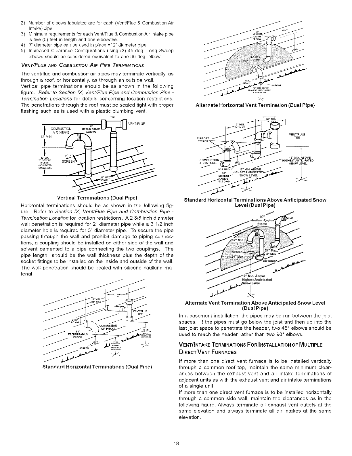
2) Number of elbows tabulated are for each (Vent/Flue & Combustion Air
Intake) pipe.
3) Minimum requirements for each Vent/Flue & Combustion Air Intake pipe
is five (5) feet in length and one elbow/tee.
4) 3" diameter pipe can be used in place of 2" diameter pipe.
5) Increased Clearance Configurations using (2) 45 deg. Long Sweep
elbows should be considered equivalent to one 90 deg. elbow.
VENT/FLuE AND COMBUSTION AIR PIPE TERMINATIONS
The vent/flue and combustion air pipes may terminate vertically, as
through a roof, or horizontally, as through an outside wall.
Vertical pipe terminations should be as shown in the following
figure. Refer to Section IX, Vent/Flue Pipe and Combustion Pipe -
Termination Locations for details concerning location restrictions.
The penetrations through the roof must be sealed tight with proper
flashing such as is used with a plastic plumbing vent.
TEE
VENT/FLUE
_ COMBUSTION
AIR INTAKE
12" MIN
Vertical Terminations (Dual Pipe)
Horizontal terminations should be as shown in the following fig-
ure. Refer to Section IX, Vent/Flue Pipe and Combustion Pipe -
Termination Location for location restrictions. A 2 3/8 inch diameter
wall penetration is required for 2" diameter pipe while a 3 1/2 inch
diameter hole is required for 3" diameter pipe. To secure the pipe
passing through the wall and prohibit damage to piping connec-
tions, a coupling should be installed on either side of the wall and
solvent cemented to a pipe connecting the two couplings. The
pipe length should be the wall thickness plus the depth of the
socket fittings to be installed on the inside and outside of the wall.
The wall penetration should be sealed with silicone caulking ma-
terial.
Alternate Horizontal Vent Termination (Dual Pipe)
Standard Horizontal Terminations Above Anticipated Snow
Level (Dual Pipe)
900
MEDIUM RADIUS
Standard Horizontal Terminations (Dual Pipe)
Alternate Vent Termination Above Anticipated Snow Level
(Dual Pipe)
In a basement installation, the pipes may be run between the joist
spaces. If the pipes must go below the joist and then up into the
last joist space to penetrate the header, two 45 ° elbows should be
used to reach the header rather than two 90 ° elbows.
VENT/INTAKE TERMINATIONSFOR INSTALLATION OF MULTIPLE
DIRECTVENT FURNACES
If more than one direct vent furnace is to be installed vertically
through a common roof top, maintain the same minimum clear-
ances between the exhaust vent and air intake terminations of
adjacent units as with the exhaust vent and air intake terminations
of a single unit.
If more than one direct vent furnace is to be installed horizontally
through a common side wall, maintain the clearances as in the
following figure. Always terminate all exhaust vent outlets at the
same elevation and always terminate all air intakes at the same
elevation.
18
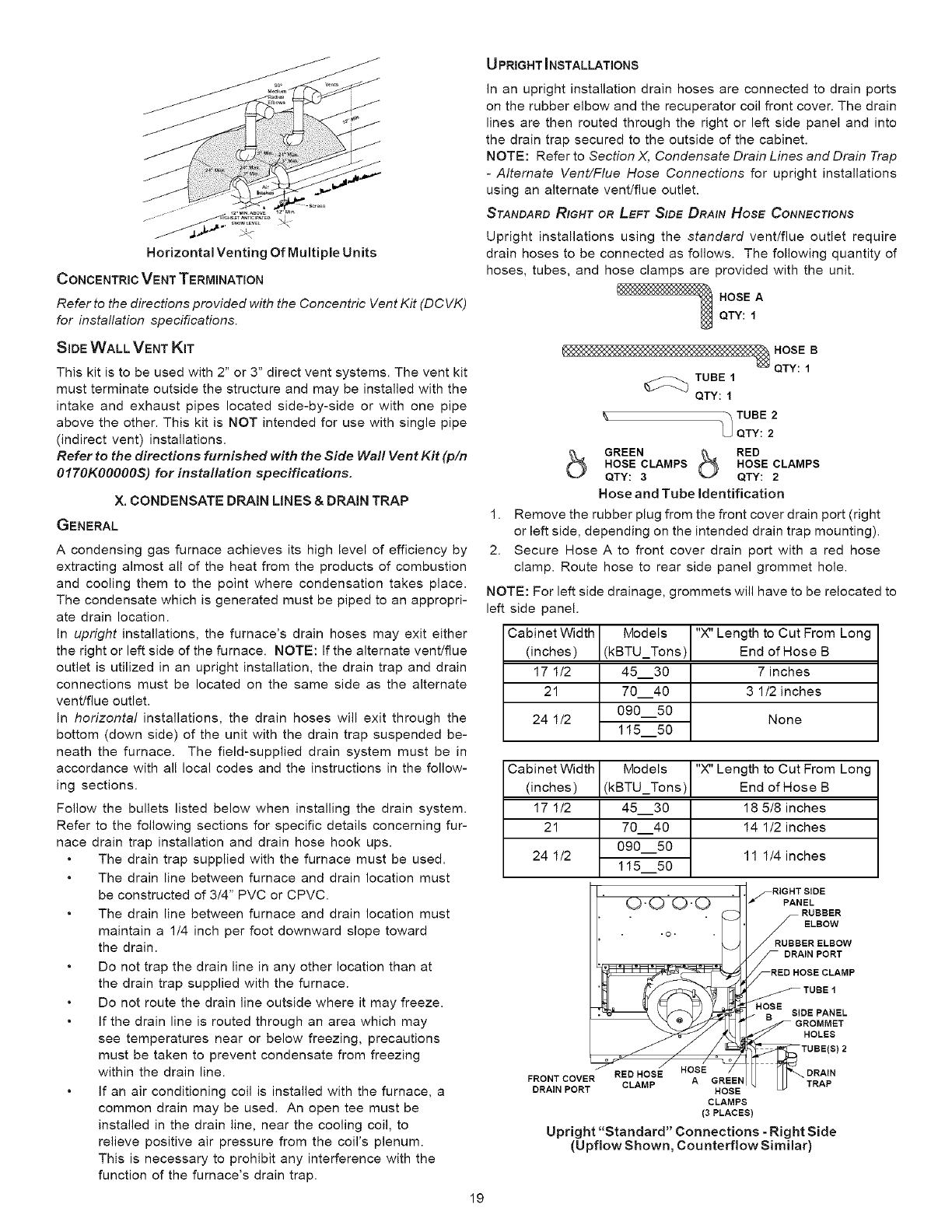
12,M1_A_OVE 12'¸M_
Horizontal Venting Of Multiple Units
CONCENTRIC VENT TERMINATION
Refer to the directions provided with the Concentric Vent Kit (DC VK)
for installation specifications.
SIDE WALL VENT KIT
This kit is to be used with 2" or 3" direct vent systems. The vent kit
must terminate outside the structure and may be installed with the
intake and exhaust pipes located side-by-side or with one pipe
above the other. This kit is NOT intended for use with single pipe
(indirect vent) installations.
Refer to the directions furnished with the Side Wall Vent Kit (pin
0170K00000S) for installation specifications.
X. CONDENSATE DRAIN LINES &DRAIN TRAP
GENERAL
A condensing gas furnace achieves its high level of efficiency by
extracting almost all of the heat from the products of combustion
and cooling them to the point where condensation takes place.
The condensate which is generated must be piped to an appropri-
ate drain location.
In upright installations, the furnace's drain hoses may exit either
the right or left side of the furnace. NOTE: If the alternate vent/flue
outlet is utilized in an upright installation, the drain trap and drain
connections must be located on the same side as the alternate
vent/flue outlet.
In horizontal installations, the drain hoses will exit through the
bottom (down side) of the unit with the drain trap suspended be-
neath the furnace. The field-supplied drain system must be in
accordance with all local codes and the instructions in the follow-
ing sections.
Follow the bullets listed below when installing the drain system.
Refer to the following sections for specific details concerning fur-
nace drain trap installation and drain hose hook ups.
The drain trap supplied with the furnace must be used.
The drain line between furnace and drain location must
be constructed of 3/4" PVC or CPVC.
The drain line between furnace and drain location must
maintain a 1/4 inch per foot downward slope toward
the drain.
Do not trap the drain line in any other location than at
the drain trap supplied with the furnace.
Do not route the drain line outside where it may freeze.
If the drain line is routed through an area which may
see temperatures near or below freezing, precautions
must be taken to prevent condensate from freezing
within the drain line.
If an air conditioning coil is installed with the furnace, a
common drain may be used. An open tee must be
installed in the drain line, near the cooling coil, to
relieve positive air pressure from the coil's plenum.
This is necessary to prohibit any interference with the
function of the furnace's drain trap.
19
U PRIGHT _NSTALLATIONS
In an upright installation drain hoses are connected to drain ports
on the rubber elbow and the recuperator coil front cover. The drain
lines are then routed through the right or left side panel and into
the drain trap secured to the outside of the cabinet.
NOTE: Refer to Section X, Condensate Drain Lines and Drain Trap
-Alternate Vent/Flue Hose Connections for upright installations
using an alternate vent/flue outlet.
STANDARD RIGHT OR LEFT SIDE DRAIN Hose CONNECTIONS
Upright installations using the standard vent/flue outlet require
drain hoses to be connected as follows. The following quantity of
hoses, tubes, and hose clamps are provided with the unit.
HOSE A
QTY: 1
HOSE B
QTY: 1
_TUBE 1
QTY: 1
"_ TUBE 2
UQTY: 2
bGREEN bRED
HOSE CLAMPS HOSE CLAMPS
QTY: 3QTY: 2
Hose and Tube Identification
1. Remove the rubber plug from the front cover drain port (right
or left side, depending on the intended drain trap mounting).
2. Secure Hose A to front cover drain port with a red hose
clamp. Route hose to rear side panel grommet hole.
NOTE: For left side drainage, grommets will have to be relocated to
left side panel.
Cabinet Width Models "X" Length to Cut From Long
(inches) (kBTU_Tons) End of Hose B
171/2 45__30 7 inches
21 70__40 31/2 inches
090__50
11550
24 1/2 None
Cabinet Width
(inches)
17 1/2
21
Models
(kBTU_Tons)
45__30
70__40
090__50
24 1/2 11 1/4 inches
11550
FRONT COVE_REE_N
DRAIN PORT CLAMP HOSE
CLAMPS
(3 PLACES)
Upright "Standard" Connections - Right Side
(Upflow Shown, Counterflow Similar)
"X" Length to Cut From Long
End of Hose B
18 5/8 inches
14 1/2 inches
RIGHT SIDE
fPANEL
RUBBER
_ELBOW
RUBBER ELBOW
IN PORT
_RED HOSE CLAMP
TUBE 1
I(_SE SIDE PANEL
GROMMET
_HOLES
TUBE(S) 2
DRAIN
_ J _"" TRAP
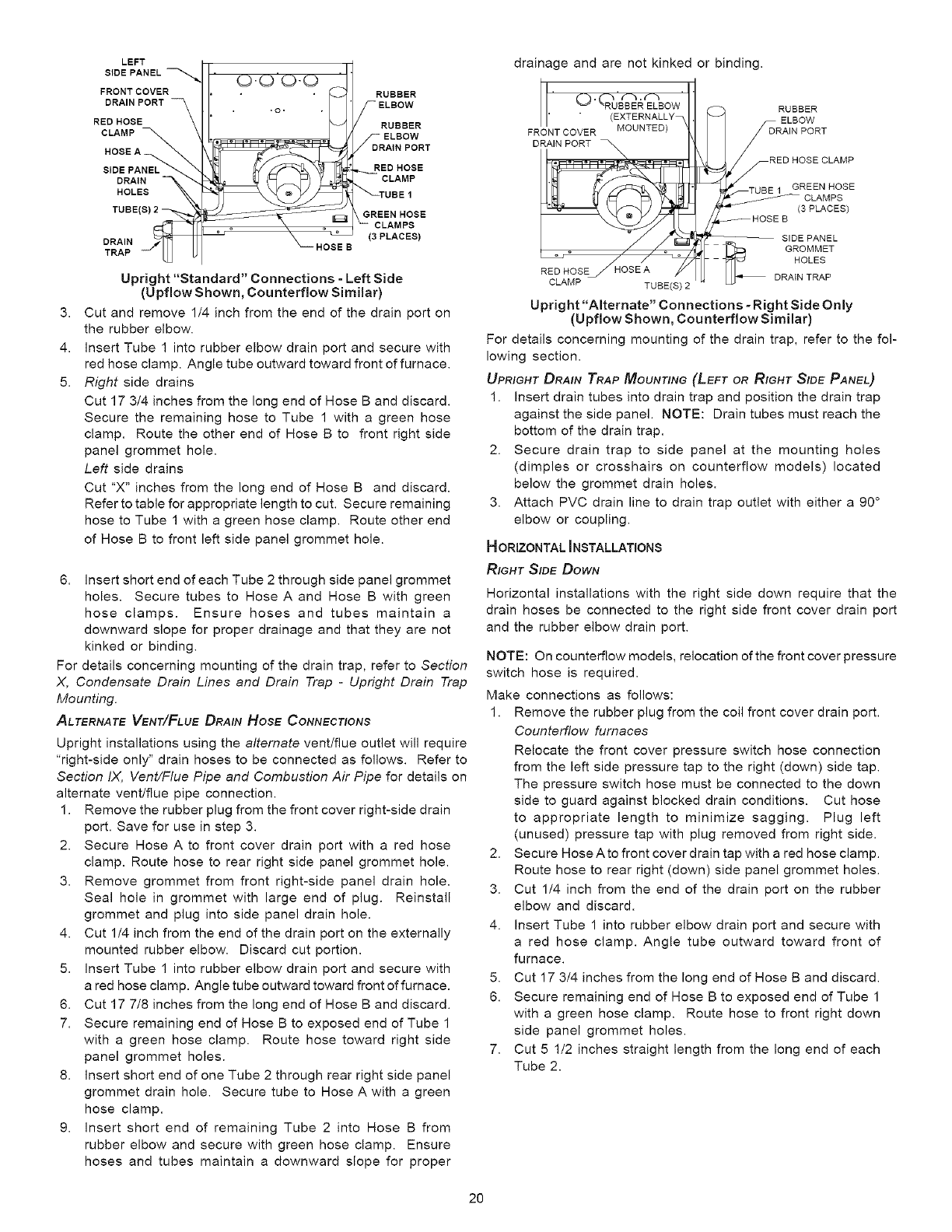
3.
4.
5.
LEFT
SIDE PANEL
FRONT COVER
DRAIN PORT
RED HOSE
CLAMP
DRAIN
HOLES
TUBE(B) 2
DRAIN
TRAP HOSE B
RUBBER
/C=]°
ELBOW
7_DRAIN PORT
..RED HOSE
CLAMP
_TUBB 1
GREEN HOSE
_CLAMPS
(3 PLACES)
Upright "Standard" Connections - Left Side
(Upflow Shown, Counterflow Similar)
Cut and remove 1/4 inch from the end of the drain port on
the rubber elbow.
Insert Tube 1 into rubber elbow drain port and secure with
red hose clamp. Angle tube outward toward front of furnace.
Right side drains
Cut 17 3/4 inches from the long end of Hose B and discard.
Secure the remaining hose to Tube 1 with a green hose
clamp. Route the other end of Hose B to front right side
panel grommet hole.
Left side drains
Cut "X" inches from the long end of Hose B and discard.
Refer to table for appropriate length to cut. Secure remaining
hose to Tube 1 with a green hose clamp. Route other end
of Hose B to front left side panel grommet hole.
6. Insert short end of each Tube 2 through side panel grommet
holes. Secure tubes to Hose A and Hose B with green
hose clamps. Ensure hoses and tubes maintain a
downward slope for proper drainage and that they are not
kinked or binding.
For details concerning mounting of the drain trap, refer to Section
X, Condensate Drain Lines and Drain Trap -Upright Drain Trap
Mounting.
ALTERNATE VENT/FLuE DRAIN HOSE CONNECTIONS
Upright installations using the alternate vent/flue outlet will require
"right-side only" drain hoses to be connected as follows. Refer to
Section IX, Vent/Flue Pipe and Combustion Air Pipe for details on
alternate vent/flue pipe connection.
1. Remove the rubber plug from the front cover right-side drain
port. Save for use in step 3.
2. Secure Hose A to front cover drain port with a red hose
clamp. Route hose to rear right side panel grommet hole.
3. Remove grommet from front right-side panel drain hole.
Seal hole in grommet with large end of plug. Reinstall
grommet and plug into side panel drain hole.
4. Cut 1/4 inch from the end of the drain port on the externally
mounted rubber elbow. Discard cut portion.
5. Insert Tube 1 into rubber elbow drain port and secure with
a red hose clamp. Angle tube outward toward front of furnace.
6. Cut 17 7/8 inches from the long end of Hose B and discard.
7. Secure remaining end of Hose B to exposed end of Tube 1
with a green hose clamp. Route hose toward right side
panel grommet holes.
8. Insert short end of one Tube 2 through rear right side panel
grommet drain hole. Secure tube to Hose A with a green
hose clamp.
9. Insert short end of remaining Tube 2 into Hose B from
rubber elbow and secure with green hose clamp. Ensure
hoses and tubes maintain a downward slope for proper
drainage and are not kinked or binding.
O (RUBBER ELBOW
(EXTERNALLY
FRONT COVER MOUNTED)
RED HOSEJ HOSE A
CLAMP TUBE(S)
RUBBER
ELBOW
RAIN PORT
ED HOSE CLAMP
_T'TUBE 1 GREEN HOSE
_ CLAMPS
(3 PLACES)
_HOSE B
_ SIDE PANEL
GROMMET
HOLES
DRAIN TRAP
Upright "Alternate" Connections - Right Side Only
(Upflow Shown, Counterflow Similar)
For details concerning mounting of the drain trap, refer to the fol-
lowing section.
UPRIGHT DRAIN TRAP MOUNTING (LEFT OR RIGHT SIDE PANEL,}
1. Insert drain tubes into drain trap and position the drain trap
against the side panel. NOTE: Drain tubes must reach the
bottom of the drain trap.
2. Secure drain trap to side panel at the mounting holes
(dimples or crosshairs on counterfiow models) located
below the grommet drain holes.
3. Attach PVC drain line to drain trap outlet with either a 90 °
elbow or coupling.
HORIZONTAL INSTALLATIONS
RIGHT SIDE DOWN
Horizontal installations with the right side down require that the
drain hoses be connected to the right side front cover drain port
and the rubber elbow drain port.
NOTE: On counterflow models, relocation of the front cover pressure
switch hose is required.
Make connections as follows:
1. Remove the rubber plug from the coil front cover drain port.
Counterflow furnaces
Relocate the front cover pressure switch hose connection
from the left side pressure tap to the right (down) side tap.
The pressure switch hose must be connected to the down
side to guard against blocked drain conditions. Cut hose
to appropriate length to minimize sagging. Plug left
(unused) pressure tap with plug removed from right side.
2. Secure Hose A to front cover drain tap with a red hose clamp.
Route hose to rear right (down) side panel grommet holes.
3. Cut 1/4 inch from the end of the drain port on the rubber
elbow and discard.
4. Insert Tube 1 into rubber elbow drain port and secure with
a red hose clamp. Angle tube outward toward front of
furnace.
5. Cut 17 3/4 inches from the long end of Hose B and discard.
6. Secure remaining end of Hose B to exposed end of Tube 1
with a green hose clamp. Route hose to front right down
side panel grommet holes.
7. Cut 5 1/2 inches straight length from the long end of each
Tube 2.
20
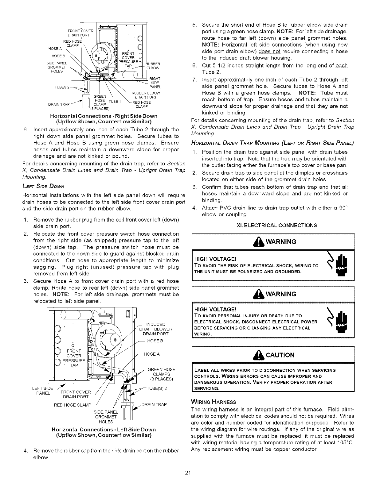
N
FRONT COVER
DRAIN PORT
RED HOSE
HOSE A CLAMP
HOSE B
SIDE PANEL
GROMMET
HOLE
c1
C
FRONT
• COVER
PRESSURE RUBBER
TAP _, ELBOW
".'i . RIGHT
_ SIDE
PANEL
RUBBERELBOW
GREEN _BE 1 _ DRAIN PORT
HOSE T RED HOSE
CLAMP CLAMP
Horizontal Connections =Right Side Down
(Upflow Shown, Counterflow Similar)
8. Insert approximately one inch of each Tube 2 through the
right down side panel grommet holes• Secure tubes to
HoseAand Hose B using green hose clamps• Ensure
hoses and tubes maintain a downward slope for proper
drainage and are not kinked or bound•
For details concerning mounting of the drain trap, refer to Section
X, Condensate Drain Lines and Drain Trap -Upright Drain Trap
Mounting.
LEFT SIDE DOWN
Horizontal installations with the left side panel down will require
drain hoses to be connected to the left side front cover drain port
and the side drain port on the rubber elbow.
1,
2.
3,
Remove the rubber plug from the coil front cover left (down)
side drain port.
Relocate the front cover pressure switch hose connection
from the right side (as shipped) pressure tap to the left
(down) side tap. The pressure switch hose must be
connected to the down side to guard against blocked drain
conditions• Cut hose to appropriate length to minimize
sagging. Plug right (unused) pressure tap with plug
removed from left side.
Secure Hose A to front cover drain port with a red hose
clamp. Route hose to rear left (down) side panel grommet
holes• NOTE: For left side drainage, grommets must be
relocated to left side panel•
oseA
I " _ "_::_p,._-_ -- GREEN HOSE
II__h/ /CLAMPS
"1 j /' ;C_=_//. _ (3 PLACES)
LEFT SIDE _ I" '// ' '_J_:_TUBE(S) 2
PANEL FRONT COVERJ / //
DRAIN PORT /£_
RED HOSE CLAMP SIGID%i_A2EE_TTL_._/DRAIN TRAP
HOLES
Horizontal Connections =Left Side Down
(Upflow Shown, Counterflow Similar)
4. Remove the rubber cap from the side drain port on the rubber
elbow.
5. Secure the short end of Hose B to rubber elbow side drain
port using a green hose clamp. NOTE: For left side drainage,
route hose to far left (down) side panel grommet holes.
NOTE: Horizontal left side connections (when using new
side port drain elbow) does not require connecting a hose
to the induced draft blower housing•
6. Cut 5 1/2 inches straight length from the long end of each
Tube 2.
7. Insert approximately one inch of each Tube 2 through left
side panel grommet hole. Secure tubes to HoseA and
Hose B with a green hose clamps. NOTE: Tube must
reach bottom of trap. Ensure hoses and tubes maintain a
downward slope for proper drainage and that they are not
kinked or binding.
For details concerning mounting of the drain trap, refer to Section
X, Condensate Drain Lines and Drain Trap -Upright Drain Trap
Mounting.
HORIZONTAL DRAIN TRAP MOUNTING (LEFT OR RIGHT SIDE PANEL)
1. Position the drain trap against side panel with drain tubes
inserted into trap. Note that the trap may be orientated with
the outlet facing either the furnace's top cover or base pan.
2. Secure drain trap to side panel at the dimples or crosshairs
located on either side of the grommet drain holes.
3. Confirm that tubes reach bottom of drain trap and that all
hoses maintain a downward slope and are not kinked or
binding.
4. Attach PVC drain line to drain trap outlet with either a 90 °
elbow or coupling.
Xl. ELECTRICAL CONNECTIONS
,_ WARNING
HIGH VOLTAGE!
To AVOID THE RISK OF ELECTRICAL SHOCK_WIRING TO
THE UNIT MUST BE POLARIZED AND GROUNDED.
,_ll, WARNING
HIGH VOLTAGE! _ _1_
To AVOID PERSONAL INJURY OR DEATH DUE TO
ELECTRICAL SHOCK_DISCONNECT ELECTRICAL POWER
BEFORE SERVICING OR CHANGING ANY ELECTRICAL
WIRING,
i_# CAUTION
LABEL ALL WIRES PRIOR TO DISCONNECTION WHEN SERVICING
CONTROLS, WIRING ERRORS CAN CAUSE IMPROPER AND
DANGEROUS OPERATION. VERIFY PROPER OPERATION AFTER
SERVICING.
WIRING HARNESS
The wiring harness is an integral part of this furnace. Field alter-
ation to comply with electrical codes should not be required. Wires
are color and number coded for identification purposes• Refer to
the wiring diagram for wire routings. If any of the original wire as
supplied with the furnace must be replaced, it must be replaced
with wiring material having a temperature rating of at least 105°C.
Any replacement wiring must be copper conductor.
21
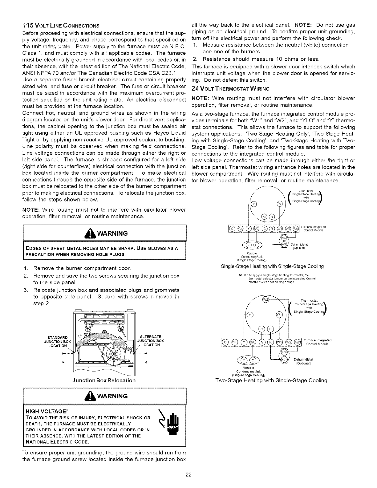
11 5 VOLT LINE CONNECTIONS
Before proceeding with electrical connections, ensure that the sup-
ply voltage, frequency, and phase correspond to that specified on
the unit rating plate. Power supply to the furnace must be N.E.C.
Class 1, and must comply with all applicable codes. The furnace
must be electrically grounded in accordance with local codes or, in
their absence, with the latest edition of The National Electric Code,
ANSi NFPA 70 and/or The Canadian Electric Code CSA C22.1.
Use a separate fused branch electrical circuit containing properly
sized wire, and fuse or circuit breaker. The fuse or circuit breaker
must be sized in accordance with the maximum overcurrent pro-
tection specified on the unit rating plate. An electrical disconnect
must be provided at the furnace location.
Connect hot, neutral, and ground wires as shown in the wiring
diagram located on the unit's blower door. For direct vent applica-
tions, the cabinet opening to the junction box must be sealed air
tight using either an UL approved bushing such as Heyco Liquid
Tight or by applying non-reactive UL approved sealant to bushing.
Line polarity must be observed when making field connections.
Line voltage connections can be made through either the right or
left side panel. The furnace is shipped configured for a left side
(right side for counterflows) electrical connection with the junction
box located inside the burner compartment. To make electrical
connections through the opposite side of the furnace, the junction
box must be relocated to the other side of the burner compartment
prior to making electrical connections. To relocate the junction box,
follow the steps shown below.
NOTE: Wire routing must not to interfere with circulator blower
operation, filter removal, or routine maintenance.
,_li, WARNING
EDGES OF SHEET METAL HOLES MAY BE SHARP. USE GLOVES AS A
PRECAUTION WHEN REMOVING HOLE PLUGS.
1. Remove the burner compartment door.
2. Remove and save the two screws securing the junction box
to the side panel.
3. Relocate junction box and associated plugs and grommets
to opposite side panel. Secure with screws removed in
step 2.
STANDARD
JUNCTION BOX
LOCATION
Junction Box Relocation
ALTERNATE
JUNCTION BOX
LOCATION
,_ll, WARNING
HIGH VOLTAGE! _ e
To AVOID THE RISK OF INJURY_ELECTRICAL SHOCK OR
DEATH_THE FURNACE MUST BE ELECTRICALLY
GROUNDED IN ACCORDANCE WITH LOCAL CODES OR IN
THEIR ABSENCE, WITH THE LATEST EDITION OF THE
NATIONAL ELECTRIC CODE.
To ensure proper unit grounding, the ground wire should run from
the furnace ground screw located inside the furnace junction box
all the way back to the electrical panel. NOTE: Do not use gas
piping as an electrical ground. To confirm proper unit grounding,
turn off the electrical power and perform the following check.
1. Measure resistance between the neutral (white) connection
and one of the burners.
2. Resistance should measure 10 ohms or less.
This furnace is equipped with a blower door interlock switch which
interrupts unit voltage when the blower door is opened for servic-
ing. Do not defeat this switch.
24 VOLT THERMOSTAT WIRING
NOTE: Wire routing must not interfere with circulator blower
operation, filter removal, or routine maintenance.
As a two-stage furnace, the furnace integrated control module pro-
vides terminals for both "WI" and "W2", and "YLO" and "Y" thermo-
stat connections. This allows the furnace to support the following
system applications: 'Two-Stage Heating Only', 'Two-Stage Heat-
ing with Single-Stage Cooling', and 'Two-Stage Heating with Two-
Stage Cooling'. Refer to the following figures and table for proper
connections to the integrated control module.
Low voltage connections can be made through either the right or
left side panel. Thermostat wiring entrance holes are located in the
blower compartment. Wire routing must not interfere with circula-
tor blower operation, filter removal, or routine maintenance.
Furn_{ce Integrated
,____i
.... ", ,*" De_umidistat
[Optional]
Remote
Condensing Unit
(Single Stage Cooling)
Single-Stage Heating with Single-Stage Cooling
NOTE: To apply a single stage heating thermostat the
thermostat selector jumper on tl_e integrated Contro_
module must be set on single stage
Thermostat
Two-Sta%Heat,o_)
Single-Stage Coolin
•[------", ,/* Dehumidistat
_ [Optiona,]
Remote
Condensing Unit
(Single-Stage Cooling)
Two-Stage Heating with Single-Stage Cooling
22
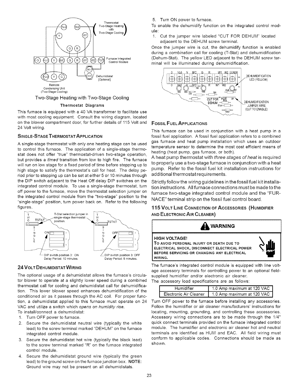
__ Thermostat
Tw°-StavgthHeating )
Two-Stage Cooling
IG Go G G d
I
_ ;_ ,I__.'@/ [Optinoidia:t]at
Remote
Condensing Unit
(Two-Stage Cooling)
Two-Stage Heating with Two-Stage Cooling
Thermostat Diagrams
This furnace is equipped with a 40 VA transformer to facilitate use
with most cooling equipment. Consult the wiring diagram, located
on the blower compartment door, for further details of 115 Volt and
24 Volt wiring.
SINGLE-STAGE THERMOSTAT APPLICATION
A single-stage thermostat with only one heating stage can be used
to control this furnace. The application of a single-stage thermo-
stat does not offer "true" thermostat-driven two-stage operation,
but provides a timed transition from low to high fire. The furnace
will run on low stage for a fixed period of time before stepping up to
high stage to satisfy the thermostat's call for heat. The delay pe-
riod prior to stepping up can be set at either 5 or 10 minutes through
the DIP switch adjacent to the Heat Off delay DIP switches on the
integrated control module. To use a single-stage thermostat, turn
off power to the furnace, move the thermostat selection jumper on
the integrated control module from the "two-stage" position to the
"single-stage" position, turn power back on. Refer to the following
figures.
T T-Star selection jumper in
W ingle-stage thermostat
_ositioo
N ON s
G
L
LDIP switch position 3: ON "DIP switch position 3: OFF
Delay Period: 10 minutes. Delay Period: 5 minutes.
24 VOLT D EHUMIDISTAT WIRING
The optional usage of a dehumidistat allows the furnace's circula-
tor blower to operate at a slightly lower speed during a combined
thermostat call for cooling and dehumidistat call for dehumidifica-
tion. This lower blower speed enhances dehumidification of the
conditioned air as it passes through the AC coil. For proper func-
tion, a dehumidistat applied to this furnace must operate on 24
VAC and utilize a switch which opens on humidity rise.
To install/connect a dehumidistat:
1. Turn OFF power to furnace.
2. Secure the dehumidistat neutral wire (typically the white
lead) to the screw terminal marked "DEHUM" on the furnace
integrated control module.
3. Secure the dehumidistat hot wire (typically the black lead)
to the screw terminal marked "R" on the furnace integrated
control module.
4. Secure the dehumidistat ground wire (typically the green
lead) to the ground screw on the furnace junction box. NOTE:
Ground wire may not be present on all dehumidistats.
5. Turn ON power to furnace.
To enable the dehumidify function on the integrated control mod-
ule:
1. Cut the jumper wire labeled "CUT FOR DEHUM" located
adjacent to the DEHUM screw terminal.
Once the jumper wire is cut, the dehumidify function is enabled
during a combination call for cooling (T-Stat) and dehumidification
(Dehum-Stat). The yellow LED adjacent to the DEHUM screw ter-
minal will be illuminated during dehumidification.
DEHUMIDIFICATION
LED(YELLOW)
DEHUMIDIFICATION
JUMPER WIRE
(CUTTO ENABLE)
FOSSIL FUEL APPLICATIONS
This furnace can be used in conjunction with a heat pump in a
fossil fuel application. A fossil fuel application refers to a combined
gas furnace and heat pump installation which uses an outdoor
temperature sensor to determine the most cost efficient means of
heating (heat pump, gas furnace, or both).
A heat pump thermostat with three stages of heat is required
to properly use a two-stage furnace in conjunction with a heat
pump. Refer to the fossil fuel kit installation instructions for
additional thermostat requirements.
Strictly follow the wiring guidelines in the fossil fuel kit installa-
tion instructions. All furnace connections must be made to the
furnace two-stage integrated control module and the "FUR-
NACE" terminal strip on the fossil fuel control board.
1 15 VOLT LINE CONNECTION OF ACCESSORIES (HUMIDIFIER
AND ELECTRONIC AIR CLEANER)
_WARNING
HIGH VOLTAGE! _ e
To AVOID PERSONAL INJURY OR DEATH DUE TO
ELECTRICAL SHOCK_DISCONNECT ELECTRICAL POWER
BEFORE SERVICING OR CHANGING ANY ELECTRICAL
WIRING.
The furnace's integrated control module is equipped with line volt-
age accessory terminals for controlling power to an optional field-
supplied humidifier and/or electronic air cleaner.
The accessory load specifications are as follows:
t Humidifier 1 .O Amp maximum at 120 VAC J
1
Electronic Air Cleaner 1.0 Amp maximum at 120 VAC
Turn OFF power to the furnace before installing any accessories.
Follow the humidifier or air cleaner manufacturers' instructions for
locating, mounting, grounding, and controlling these accessories.
Accessory wiring connections are to be made through the 1/4"
quick connect terminals provided on the furnace integrated control
module. The humidifier and electronic air cleaner hot and neutral
terminals are identified as HUM and EAC. All field wiring must
conform to applicable codes. Connections should be made as
shown.
23
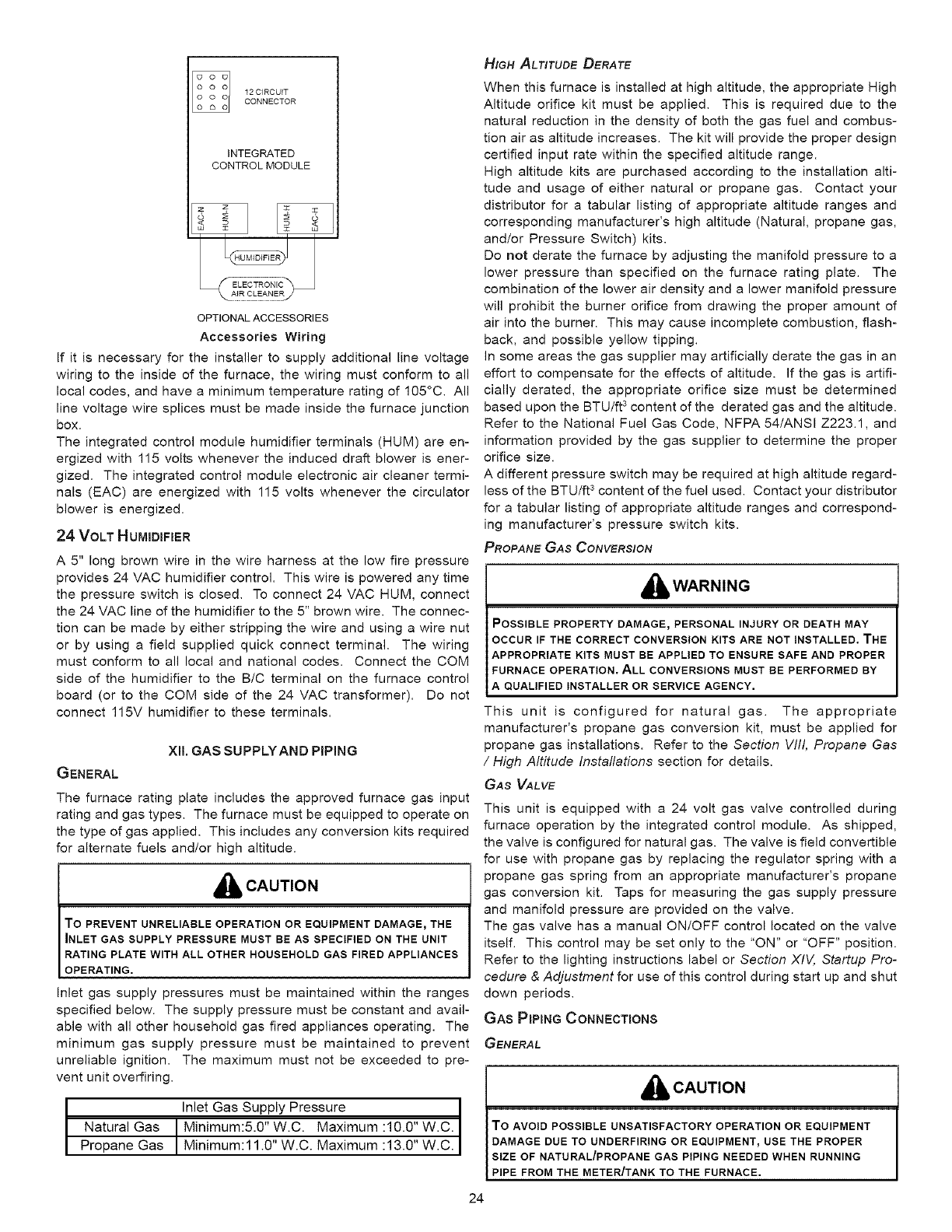
12 CIRCUITCONNECTOR
INTEGRATED
CONTROL MODULE
OPTIONAL ACCESSORIES
Accessories Wiring
If it is necessary for the installer to supply additional line voltage
wiring to the inside of the furnace, the wiring must conform to all
local codes, and have a minimum temperature rating of 105°C. All
line voltage wire splices must be made inside the furnace junction
box.
The integrated control module humidifier terminals (HUM) are en-
ergized with 115 volts whenever the induced draft blower is ener-
gized. The integrated control module electronic air cleaner termi-
nals (EAC) are energized with 115 volts whenever the circulator
blower is energized.
24 VOLT HUMiDiFIER
A 5" long brown wire in the wire harness at the low fire pressure
provides 24 VAC humidifier control. This wire is powered any time
the pressure switch is closed. To connect 24 VAC HUM, connect
the 24 VAC line of the humidifier to the 5" brown wire. The connec-
tion can be made by either stripping the wire and using a wire nut
or by using a field supplied quick connect terminal. The wiring
must conform to all local and national codes. Connect the COM
side of the humidifier to the B/C terminal on the furnace control
board (or to the COM side of the 24 VAC transformer). Do not
connect 115V humidifier to these terminals.
Xll, GAS SUPPLYAND PIPING
GENERAL
The furnace rating plate includes the approved furnace gas input
rating and gas types. The furnace must be equipped to operate on
the type of gas applied. This includes any conversion kits required
for alternate fuels and/or high altitude.
_, CAUTION
TO PREVENT UNRELIABLE OPERATION OR EQUIPMENT DAMAGE, THE
INLET GAS SUPPLY PRESSURE MUST BE AS SPECIFIED ON THE UNIT
RATING PLATE WITH ALL OTHER HOUSEHOLD GAS FIRED APPLIANCES
OPERATING.
Inlet gas supply pressures must be maintained within the ranges
specified below. The supply pressure must be constant and avail-
able with all other household gas fired appliances operating. The
minimum gas supply pressure must be maintained to prevent
unreliable ignition. The maximum must not be exceeded to pre-
vent unit overfiring.
Inlet Gas Supply Pressure
Natural Gas Minimum:5.0" W.C. Maximum :10.0" W.C.
PropaneGas Mnmum:11.0 W.C. Max mum :13.0 W.C.
HIGH ALTITUDE DERATE
When this furnace is installed at high altitude, the appropriate High
Altitude orifice kit must be applied. This is required due to the
natural reduction in the density of both the gas fuel and combus-
tion air as altitude increases. The kit will provide the proper design
certified input rate within the specified altitude range.
High altitude kits are purchased according to the installation alti-
tude and usage of either natural or propane gas. Contact your
distributor for a tabular listing of appropriate altitude ranges and
corresponding manufacturer's high altitude (Natural, propane gas,
and/or Pressure Switch) kits.
Do not derate the furnace by adjusting the manifold pressure to a
lower pressure than specified on the furnace rating plate. The
combination of the lower air density and a lower manifold pressure
will prohibit the burner orifice from drawing the proper amount of
air into the burner. This may cause incomplete combustion, flash-
back, and possible yellow tipping.
In some areas the gas supplier may artificially derate the gas in an
effort to compensate for the effects of altitude. If the gas is artifi-
cially derated, the appropriate orifice size must be determined
based upon the BTU/ft 3 content of the derated gas and the altitude.
Refer to the National Fuel Gas Code, NFPA 54/ANSI Z223.1, and
information provided by the gas supplier to determine the proper
orifice size.
A different pressure switch may be required at high altitude regard-
less of the BTU/ft 3 content of the fuel used. Contact your distributor
for a tabular listing of appropriate altitude ranges and correspond-
ing manufacturer's pressure switch kits.
PROPANE GAS CONVERSION
i_lb WARNING
POSSIBLE PROPERTY DAMAGE, PERSONAL INJURY OR DEATH MAY
OCCUR IF THE CORRECT CONVERSION KITS ARE NOT INSTALLED. THE
APPROPRIATE KITS MUST BE APPLIED TO ENSURE SAFE AND PROPER
FURNACE OPERATION. ALL CONVERSIONS MUST BE PERFORMED BY
A QUALIFIED INSTALLER OR SERVICE AGENCY.
This unit is configured for natural gas. The appropriate
manufacturer's propane gas conversion kit, must be applied for
propane gas installations. Refer to the Section WII, Propane Gas
/ High Altitude Instaflationa section for details.
GAS VALVE
This unit is equipped with a 24 volt gas valve controlled during
furnace operation by the integrated control module. As shipped,
the valve is configured for natural gas. The valve is field convertible
for use with propane gas by replacing the regulator spring with a
propane gas spring from an appropriate manufacturer's propane
gas conversion kit. Taps for measuring the gas supply pressure
and manifold pressure are provided on the valve.
The gas valve has a manual ON/OFF control located on the valve
itself. This control may be set only to the "ON" or "OFF" position.
Refer to the lighting instructions label or Section XIV,, Startup Pro-
cedure & Adjustment for use of this control during start up and shut
down periods.
GAS PiPiNG CONNECTIONS
GENERAL
i_lj CAUTION
TO AVOID POSSIBLE UNSATISFACTORY OPERATION OR EQUIPMENT
DAMAGE DUE TO UNDERFIRING OR EQUIPMENT, USE THE PROPER
SIZE OF NATURAL/PROPANE GAS PIPING NEEDED WHEN RUNNING
PIPE FROM THE METER/TANK TO THE FURNACE.
24
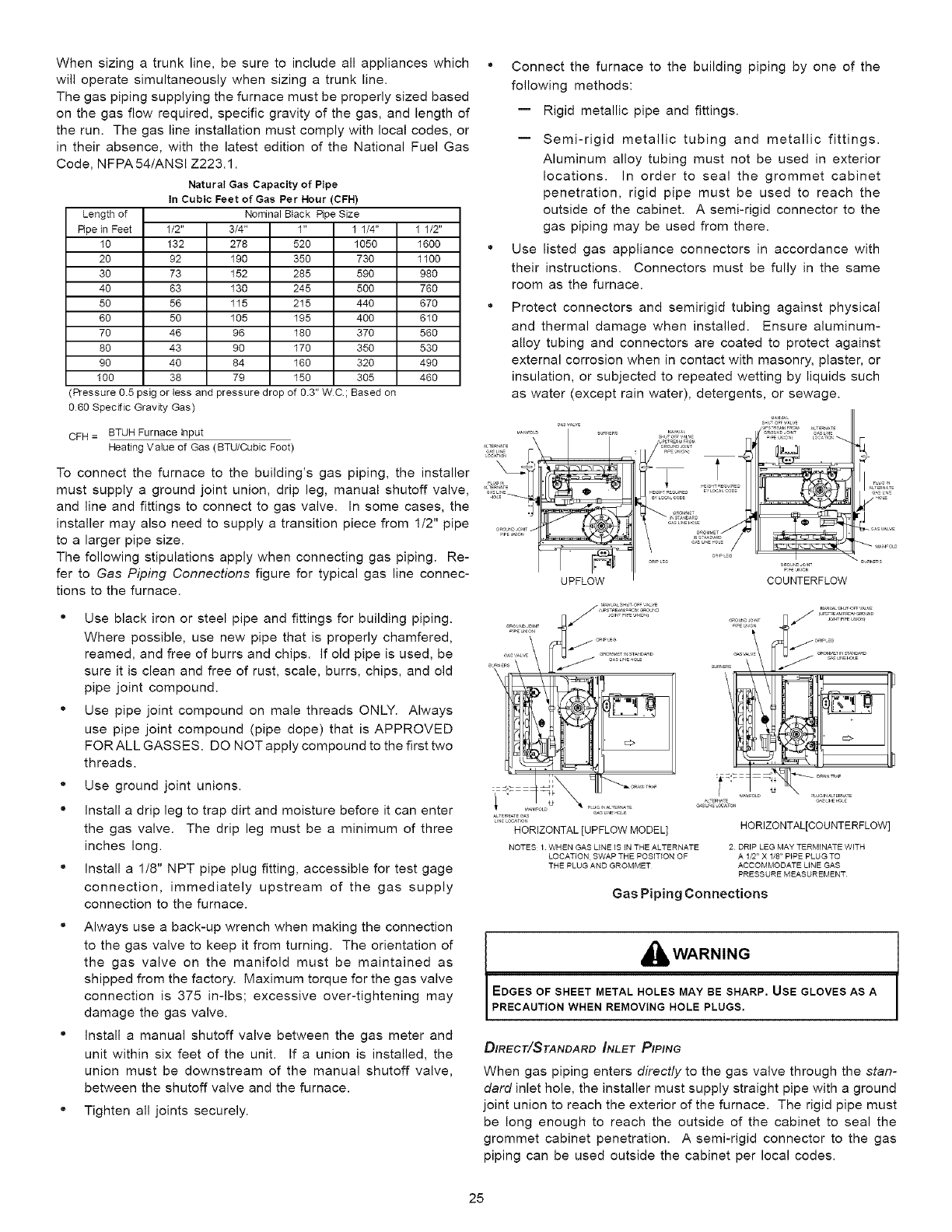
When sizing a trunk line, be sure to include all appliances which
will operate simultaneously when sizing a trunk line.
The gas piping supplying the furnace must be properly sized based
on the gas flow required, specific gravity of the gas, and length of
the run. The gas line installation must comply with local codes, or
in their absence, with the latest edition of the National Fuel Gas
Code, NFPA 54/ANSI Z223.1.
Natural Gas Capacity of Pipe
In Cubic Feet of Gas Per Hour (CFH)
Length of Nominal Btack Ripe Size
Ripe in Feet 1/2" 3/4" 1" 1 1/4" 1 1/2"
10 132 278 520 1050 1600
20 92 190 350 730 1100
30 73 152 285 590 980
40 63 130 245 500 760
50 56 115 215 440 670
60 50 105 195 400 610
70 46 96 180 370 560
80 43 90 170 350 530
90 40 84 160 320 490
100 38 79 150 305 460
Pressure 0.5 psig or tess and pressure drop of 0.3" WC; Based OR
060 Specific Gravity Gas)
CFH = BTUH Furnace Input
Heating VaIue of Gas (BTU/Cubic Foot)
To connect the furnace to the building's gas piping, the installer
must supply a ground joint union, drip leg, manual shutoff valve,
and line and fittings to connect to gas valve. In some cases, the
installer may also need to supply a transition piece from 1/2" pipe
to a larger pipe size.
The following stipulations apply when connecting gas piping. Re-
fer to Gas Piping Connections figure for typical gas line connec-
tions to the furnace.
" Use black iron or steel pipe and fittings for building piping.
Where possible, use new pipe that is properly chamfered,
reamed, and free of burrs and chips. If old pipe is used, be
sure it is clean and free of rust, scale, burrs, chips, and old
pipe joint compound.
°Use pipe joint compound on male threads ONLY. Always
use pipe joint compound (pipe dope) that is APPROVED
FOR ALL GASSES. DO NOT apply compound to the first two
threads.
°Use ground joint unions.
" Install a drip leg to trap dirt and moisture before it can enter
the gas valve. The drip leg must be a minimum of three
inches long.
" Install a 1/8" NPT pipe plug fitting, accessible for test gage
connection, immediately upstream of the gas supply
connection to the furnace.
" Always use a back-up wrench when making the connection
to the gas valve to keep it from turning. The orientation of
the gas valve on the manifold must be maintained as
shipped from the factory. Maximum torque for the gas valve
connection is 375 in-lbs; excessive over-tightening may
damage the gas valve.
" Install a manual shutoff valve between the gas meter and
unit within six feet of the unit. If a union is installed, the
union must be downstream of the manual shutoff valve,
between the shutoff valve and the furnace.
" Tighten all joints securely.
Connect the furnace to the building piping by one of the
following methods:
-- Rigid metallic pipe and fittings.
-- Semi-rigid metallic tubing and metallic fittings.
Aluminum alloy tubing must not be used in exterior
locations. In order to seal the grommet cabinet
penetration, rigid pipe must be used to reach the
outside of the cabinet. A semi-rigid connector to the
gas piping may be used from there.
Use listed gas appliance connectors in accordance with
their instructions. Connectors must be fully in the same
room as the furnace.
Protect connectors and semirigid tubing against physical
and thermal damage when installed. Ensure aluminum-
alloy tubing and connectors are coated to protect against
external corrosion when in contact with masonry, plaster, or
insulation, or subjected to repeated wetting by liquids such
as water (except rain water), detergents, or sewage.
_Rc,_r_J_r_zJ
e_r_E_s
UPFLOW COUNTERFLOW
........... /;;;_>_:_%
HORIZONTAL [UPFLOW MODEL]
NOTES 1 WHEN GAS LINE IS IN THE ALTERNATE
LOCATION SWAP THE POSITION OF
THE PLUG AND GROMMET
HORIZONTAL[COUNTERFLOW]
2 DRIP LEG MAY TERMINATE WITH
A 1/2" X 1/8" PIPE PLUG TO
ACCOMMODATE LINE GAS
PRESSURE MEASUREMENT
Gas Piping Connections
_WARNING
EDGES OF SHEET METAL HOLES MAY BE SHARP. USE GLOVES AS A
PRECAUTION WHEN REMOVING HOLE PLUGS.
DIRECT/STANDARD _NLET PIPING
When gas piping enters directly to the gas valve through the stan-
dard inlet hole, the installer must supply straight pipe with a ground
joint union to reach the exterior of the furnace. The rigid pipe must
be long enough to reach the outside of the cabinet to seal the
grommet cabinet penetration. A semi-rigid connector to the gas
piping can be used outside the cabinet per local codes.
25
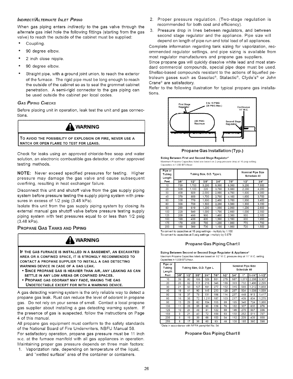
INDIRECT/ALTERNATE INLET P/PING
When gas piping enters indirectly to the gas valve through the
alternate gas inlet hole the following fittings (starting from the gas
valve) to reach the outside of the cabinet must be supplied:
*Coupling.
" 90 degree elbow.
*2 inch close nipple.
" 90 degree elbow.
*Straight pipe, with a ground joint union, to reach the exterior
of the furnace. The rigid pipe must be long enough to reach
the outside of the cabinet so as to seal the grommet cabinet
penetration. A semi-rigid connector to the gas piping can
be used outside the cabinet per local codes.
GAS P/PING CHECKS
Before placing unit in operation, leak test the unit and gas connec-
tions.
,_ WARNING
TO AVOID THE POSSIBILITY OF EXPLOSION OR FIRE, NEVER USE A
MATCH OR OPEN FLAME TO TEST FOR LEAKS.
Check for leaks using an approved chloride-free soap and water
solution, an electronic combustible gas detector, or other approved
testing methods.
NOTE: Never exceed specified pressures for testing. Higher
pressure may damage the gas valve and cause subsequent
overfiring, resulting in heat exchanger failure.
Disconnect this unit and shutoff valve from the gas supply piping
system before pressure testing the supply piping system with pres-
sures in excess of 1/2 psig (3.48 kPa).
Isolate this unit from the gas supply piping system by closing its
external manual gas shutoff valve before pressure testing supply
piping system with test pressures equal to or less than 1/2 psig
(3.48 kPa).
PROPANE GAS TANKS AND PIPING
_WARNING
IF THE GAS FURNACE IS INSTALLED IN A BASEMENT, AN EXCAVATED
AREA OR A CONFINED SPACE_ IT IS STRONGLY RECOMMENDED TO
CONTACT A PROPANE SUPPLIER TO INSTALL A GAS DETECTING
WARNING DEVICE IN CASE OF A GAS LEAK.
• SINCE PROPANE GAS IS HEAVIER THAN AIR_ ANY LEAKING AS CAN
SETTLE IN ANY LOW AREAS OR CONFINED SPACES.
• PROPANE GAS ODORANT MAY FADE_ MAKING THE GAS
UNDETECTABLE EXCEPT FOR WITH A WARNING DEVICE.
A gas detecting warning system is the only reliable way to detect a
propane gas leak. Rust can reduce the level of odorant in propane
gas. Do not rely on your sense of smell. Contact a local propane
gas supplier about installing a gas detecting warning system. If
the presence of gas is suspected, follow the instructions on Page
4 of this manual.
All propane gas equipment must conform to the safety standards
of the National Board of Fire Underwriters, NBFU Manual 58.
For satisfactory operation, propane gas pressure must be 11 inch
w.c. at the furnace manifold with all gas appliances in operation.
Maintaining proper gas pressure depends on three main factors:
1. Vaporization rate, depending on temperature of the liquid,
and "wetted surface" area of the container or containers.
2. Proper pressure regulation. (Two-stage regulation is
recommended for both cost and efficiency).
3. Pressure drop in lines between regulators, and between
second stage regulator and the appliance. Pipe size will
depend on length of pipe run and total load of all appliances.
Complete information regarding tank sizing for vaporization, rec-
ommended regulator settings, and pipe sizing is available from
most regulator manufacturers and propane gas suppliers.
Since propane gas will quickly dissolve white lead and most stan-
dard commercial compounds, special pipe dope must be used.
Shellac-based compounds resistant to the actions of liquefied pe-
troleum gases such as Gasolac _, Stalactic ®, Clyde's ® or John
Crane ® are satisfactory.
Refer to the following illustration for typical propane gas installa-
tions.
5to t5 PSIG
F_ ;tu Sttagre (20 PS,G Max) Conti .....
_ _200 PStG Second Stage
Propane Gas Installation (Typ.)
Sizing Between First and Second Stage Regulator*
Maximum Propane Capacities listed are based or_ 2 psEg pressure drop at 10 psEg setting
Capacities ir_ I 000 BTU hour
Pipe or Nominal Pipe Size
Tubing Tubing Size, O.D. Type L Schedule 40
Length
Feet 3/8" 112" 5/8" 3/4" 7/8" 1/2" 3/4"
10 730 1,700 3,200 5,300 8.300 3,200 7,500
20 500 1,100 220 3,700 5,800 2,200 4,200
30 400 920 2,000 2,900 4.700 1,800 4,500
40 370 850 1,700 2,700 4.100 1,600 3,700
50 330 770 1,500 2,400 3.700 1,500 3,400
60 300 700 1,300 2,200 3.300 1,300 3,100
80 280 610 1,200 1,900 2,900 1,200 2,600
100 220 540 1,000 1,700 2,600 1,000 2,300
125 200 490 900 1,400 2.300 900 2,100
150 190 430 830 1,300 2.100 830 1,900
175 170 400 780 1,200 1.900 770 1,700
200 160 380 730 1,100 1.800 720 1,500
To convert to capacities at 15 psig settings - multiply by 1 130
To convert to capacities at 5 psig settings - multiply by 0¸879
Propane Gas Piping Chart I
Sizing Between Second or Second Stage Regulator & Appliance*
Maximum Propane Capacities listed are based on 1/2" WC pressure drop at 1l'r WC setting
Capacities in 1,000 BTU/hour
Pipe or Nominal Pipe Size
Tubing Tubing Size, O.D. Type L Schedule 40
Length
Feet 3/8" 112" 5/8" 3/4" 7/8" 1/2" 314" 1" 1-1/4" 1=1/2"
10 39 92 199 329 501 275 567 1,071 2,205 3,307
20 28 62 131 216 346 189 393 732 1,496 2,299
30 21 50 107 181 277 152 315 590 1,212 1,858
40 19 41 90 145 233 129 267 504 1,039 1,559
50 18 37 79 131 198 114 237 448 913 1,417
60 18 35 72 1,211 187 103 217 409 834 1,275
80 13 29 62 104 155 89 185 346 724 1,066
100 11 26 55 90 138 78 162 307 630 976
125 10 24 48 81 122 69 146 275 587 886
150 9 21 43 72 109 63 132 252 511 787
200 8 19 39 86 100 54 112 209 439 885
250 8 17 36 80 93 48 100 185 390 590
*Datain accordance with NPPA pamphlet No54
Propane Gas Piping Chart II
26
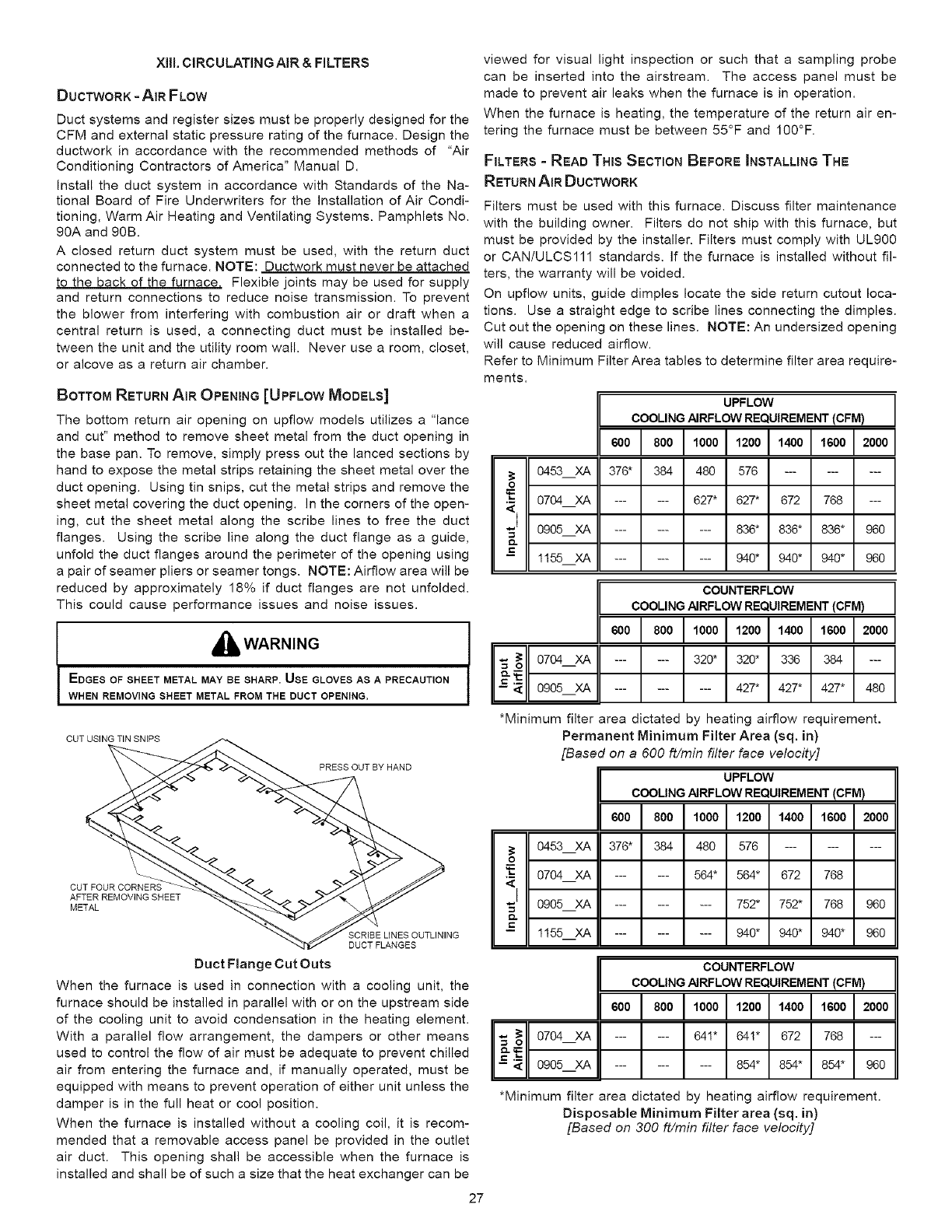
XilLCIRCULATINGAIR&FILTERS
DUCTWORK -AIR FLOW
Duct systems and register sizes must be properly designed for the
CFM and external static pressure rating of the furnace. Design the
ductwork in accordance with the recommended methods of "Air
Conditioning Contractors of America" Manual D.
Install the duct system in accordance with Standards of the Na-
tional Board of Fire Underwriters for the Installation of Air Condi-
tioning, Warm Air Heating and Ventilating Systems. Pamphlets No.
90A and 90B.
A closed return duct system must be used, with the return duct
connected to the furnace. NOTE: Ductwork must never be attached
to the back of the furnace. Flexible joints may be used for supply
and return connections to reduce noise transmission. To prevent
the blower from interfering with combustion air or draft when a
central return is used, a connecting duct must be installed be-
tween the unit and the utility room wall. Never use a room, closet,
or alcove as a return air chamber.
BOTTOM RETURN AIR OPENING [UPFLOW MODELS]
The bottom return air opening on upflow models utilizes a "lance
and cut" method to remove sheet metal from the duct opening in
the base pan. To remove, simply press out the lanced sections by
hand to expose the metal strips retaining the sheet metal over the
duct opening. Using tin snips, cut the metal strips and remove the
sheet metal covering the duct opening. In the corners of the open-
ing, cut the sheet metal along the scribe lines to free the duct
flanges. Using the scribe line along the duct flange as a guide,
unfold the duct flanges around the perimeter of the opening using
a pair of seamer pliers or seamer tongs. NOTE: Airflow area will be
reduced by approximately 18% if duct flanges are not unfolded.
This could cause performance issues and noise issues.
,_ WARNING
EDGES OF SHEET METAL MAY BE SHARP. USE GLOVES AS A PRECAUTION
WHEN REMOVING SHEET METAL FROM THE DUCT OPENING,
viewed for visual light inspection or such that a sampling probe
can be inserted into the airstream. The access panel must be
made to prevent air leaks when the furnace is in operation.
When the furnace is heating, the temperature of the return air en-
tering the furnace must be between 55°F and 100°F.
FILTERS - READ THIS SECTION BEFORE INSTALLING THE
RETURN AiR DUCTWORK
0453 XA
Filters must be used with this furnace. Discuss filter maintenance
with the building owner. Filters do not ship with this furnace, but
must be provided by the installer. Filters must comply with UL900
or CAN/ULCS111 standards. If the furnace is installed without fil-
ters, the warranty will be voided.
On upflow units, guide dimples locate the side return cutout loca-
tions. Use a straight edge to scribe lines connecting the dimples.
Cut out the opening on these lines. NOTE: An undersized opening
will cause reduced airflow.
Refer to Minimum Filter Area tables to determine filter area require-
ments.
UPFLOW J
COOLING AIRFLOW REQUIREMENT (CFM)
I.ool I,ooo1,2ooIt4oo1,6oo12oooI
376* 384 480 576 .........
0704 XA ...... 627* 627* 672 768 ---
_=
0905 XA
1155 XA
......... 836* 836* 836* 960
......... 940* 940* 940* 960
COUNTERFLOW
COOLING AIRFLOW REQUIREMENT (CFM)
I.ool6ooI,ooo1,2oo1,4oo1,6ooI oooI
...... 320* 320* 336 384 ---
...... 427* 427* 427* 480
CUT USING TiN SNIPS
PRESS OUT BY HAND
*Minimum filter area dictated by heating airflow requirement.
Permanent Minimum Filter Area (sq. in)
[Based on a 600 ft/min filter face velocity]
UPFLOW
COOLING AIRFLOW REQUIREMENT (CFM)
6001 I,oooI, oo1,4oo1,6ooI ooo
CUT FOUR CORNERS
AFTER REMOVING SHEET
METAL
SCRIBE LINES OUTLINING
DUCT FLANGES
0453XA 376* 384 480 576 .........
o
i0704 XA ...... 564* 564* 672 768
I 0905 XA ......... 752* 752* 768 960
-- 1155 XA ......... 940* 940* 940* 960
Duet Flange Cut Outs
When the furnace is used in connection with a cooling unit, the
furnace should be installed in parallel with or on the upstream side
of the cooling unit to avoid condensation in the heating element.
With a parallel flow arrangement, the dampers or other means
used to control the flow of air must be adequate to prevent chilled
air from entering the furnace and, if manually operated, must be
equipped with means to prevent operation of either unit unless the
damper is in the full heat or cool position.
When the furnace is installed without a cooling coil, it is recom-
mended that a removable access panel be provided in the outlet
air duct. This opening shall be accessible when the furnace is
installed and shall be of such a size that the heat exchanger can be
"_ _o 0704 XA
i _ 0905 XA
COUNTERFLOW
COOLING AIRFLOW REQUIREMENT (CFM)
6001.oi,oooi, ooi,4ooi,6oo12ooo
...... 641" 64!* 672 768 ---
......... 854* 854* 854* 960
*Minimum filter area dictated by heating airflow requirement.
Disposable Minimum Filter area (sq. in)
[Based on 300 ft/min filter face velocity]
27
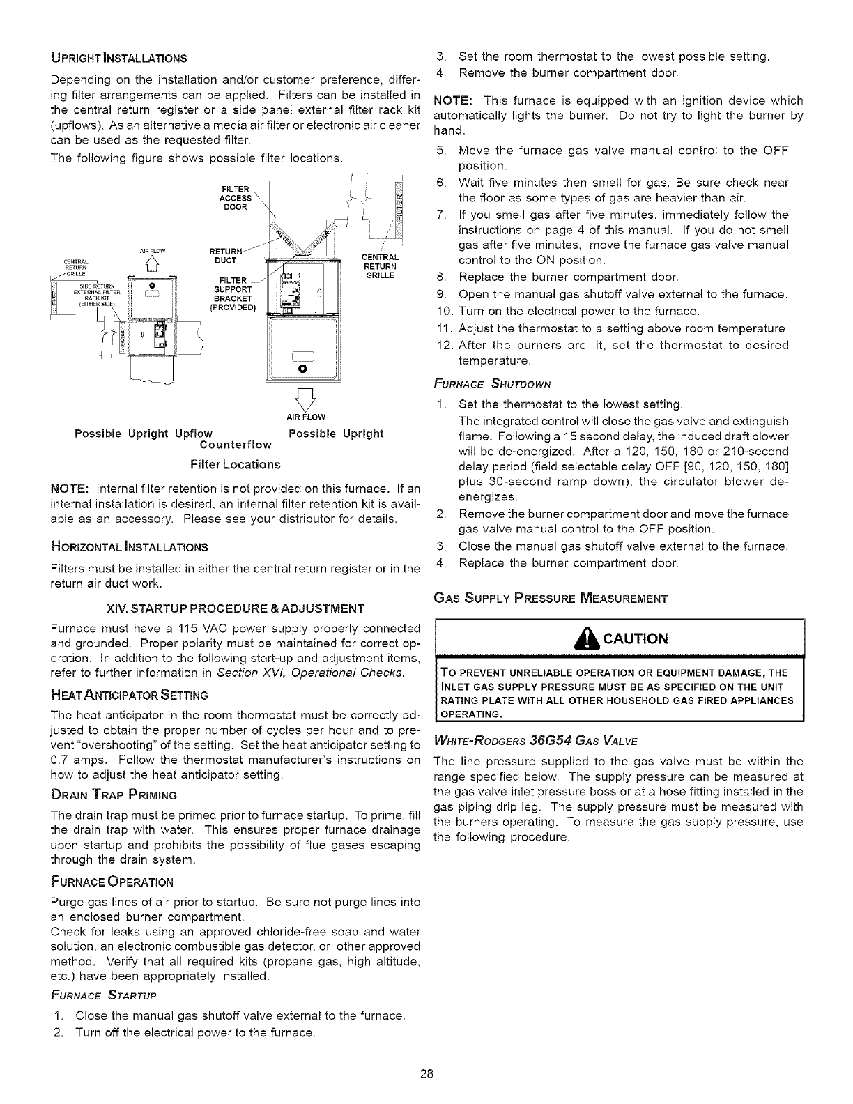
UPRIGHT _NSTALLATIONS
Depending on the installation and/or customer preference, differ-
ing filter arrangements can be applied. Filters can be installed in
the central return register or a side panel external filter rack kit
(upflows). As an alternative a media air filter or electronic air cleaner
can be used as the requested filter.
The following figure shows possible filter locations.
CENTRAL
RETURN
j GRILLE
SIDE_TURN
EXTERNALFILTER
__RACK KIT
FILTER_
ACCESS
DOOR
o
AIRFLOW RETURN -jj
,_ DUCT
FILTER /
SUPPORT
BRACKET
(PROVIDED)
Possible Upright Upflow
Counterflow
Filter Locations
I '
CIENIilR'AL i?.3u "N
0
AIR FLOW
Possible Upright
NOTE: Internal filter retention is not provided on this furnace. If an
internal installation is desired, an internal filter retention kit is avail-
able as an accessory. Please see your distributor for details.
HORIZONTAL INSTALLATIONS
Filters must be installed in either the central return register or in the
return air duct work.
XiV. STARTUP PROCEDURE &ADJUSTMENT
Furnace must have a 115 VAC power supply properly connected
and grounded. Proper polarity must be maintained for correct op-
eration. In addition to the following start-up and adjustment items,
refer to further information in Section XVI, Operational Checks.
HEAT ANTICIPATOR SETTING
The heat anticipator in the room thermostat must be correctly ad-
justed to obtain the proper number of cycles per hour and to pre-
vent "overshooting" of the setting. Set the heat anticipator setting to
0.7 amps. Follow the thermostat manufacturer's instructions on
how to adjust the heat anticipator setting.
DRAIN TRAP PRIMING
The drain trap must be primed prior to furnace startup. To prime, fill
the drain trap with water. This ensures proper furnace drainage
upon startup and prohibits the possibility of flue gases escaping
through the drain system.
FURNACE OPERATION
Purge gas lines of air prior to startup. Be sure not purge lines into
an enclosed burner compartment.
Check for leaks using an approved chloride-free soap and water
solution, an electronic combustible gas detector, or other approved
method. Verify that all required kits (propane gas, high altitude,
etc.) have been appropriately installed.
FURNACE STARTUP
1. Close the manual gas shutoff valve external to the furnace.
2. Turn off the electrical power to the furnace.
3. Set the room thermostat to the lowest possible setting.
4. Remove the burner compartment door.
NOTE: This furnace is equipped with an ignition device which
automatically lights the burner. Do not try to light the burner by
hand.
5. Move the furnace gas valve manual control to the OFF
position.
6. Wait five minutes then smell for gas. Be sure check near
the floor as some types of gas are heavier than air.
7. If you smell gas after five minutes, immediately follow the
instructions on page 4 of this manual. If you do not smell
gas after five minutes, move the furnace gas valve manual
control to the ON position.
8. Replace the burner compartment door.
9. Open the manual gas shutoff valve external to the furnace.
10. Turn on the electrical power to the furnace.
11. Adjust the thermostat to a setting above room temperature.
12. After the burners are lit, set the thermostat to desired
temperature.
FURNACE SHUTDOWN
1. Set the thermostat to the lowest setting.
The integrated control will close the gas valve and extinguish
flame. Following a 15 second delay, the induced draft blower
will be de-energized. After a 120, 150, 180 or 210-second
delay period (field selectable delay OFF [90, 120, 150, 180]
plus 30-second ramp down), the circulator blower de-
energizes.
2. Remove the burner compartment door and move the furnace
gas valve manual control to the OFF position.
3. Close the manual gas shutoff valve external to the furnace.
4. Replace the burner compartment door.
GAS SUPPLY PRESSURE MEASUREMENT
_[ll, CAUTION
To PREVENT UNRELIABLE OPERATION OR EQUIPMENT DAMAGE rTHE
INLET GAS SUPPLY PRESSURE MUST BE AS SPECIFIED ON THE UNIT
RATING PLATE WITH ALL OTHER HOUSEHOLD GAS FIRED APPLIANCES
OPERATING.
WH/TE=RODGERS 36G54 GAS VALVE
The line pressure supplied to the gas valve must be within the
range specified below. The supply pressure can be measured at
the gas valve inlet pressure boss or at a hose fitting installed in the
gas piping drip leg. The supply pressure must be measured with
the burners operating. To measure the gas supply pressure, use
the following procedure.
28
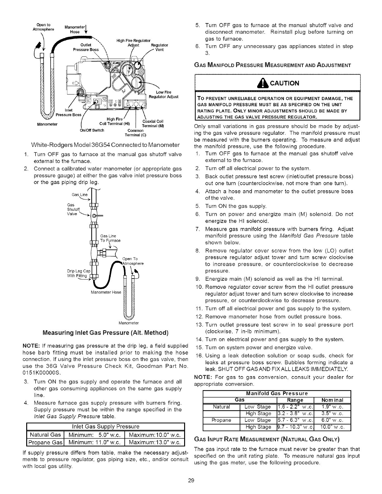
1.
2.
Open to
Atmo._ _here Manometer
Hose _r
l_lIOutlet _ \ High Fire Regulator Regulator
Pressure Boss \Vent
t
Low Fire
Regulator Adjust
inlet
Pressure Boss
Coaxial Coil
anometer Coil Terminal (HI) Terminal (M)
On/Off Switch Common
Terminal (C)
White-Rodgers Model 36G54 Connected to Manometer
Turn OFF gas to furnace at the manual gas shutoff valve
external to the furnace.
Connect a calibrated water manometer (or appropriate gas
pressure gauge) at either the gas valve inlet pressure boss
or the gas piping drip leg.
Gas Line
Gas
Shutoff
Valve _
To Furnace
Drip Leg Ca_
With
Open To
Manometer Hose
Manometer
Measuring Inlet Gas Pressure (AIt. Method)
NOTE: If measuring gas pressure at the drip leg, a field supplied
hose barb fitting must be installed prior to making the hose
connection. If using the inlet pressure boss on the gas valve, then
use the 36G Valve Pressure Check Kit, Goodman Part No.
0151KOOOOOS.
3. Turn ON the gas supply and operate the furnace and all
other gas consuming appliances on the same gas supply
line.
4. Measure furnace gas supply pressure with burners firing.
Supply pressure must be within the range specified in the
Inlet Gas Supply Pressure table.
Inlet Gas Supply Pressure I
Natural Gas I Minimum: 5.0" w.c. Maximum:10.0" w.c. J
1
Propane Gasl Minimum: 11.0" w.c. Maximum:13.0" w.c.
If supply pressure differs from table, make the necessary adjust-
ments to pressure regulator, gas piping size, etc., and/or consult
with local gas utility.
5. Turn OFF gas to furnace at the manual shutoff valve and
disconnect manometer. Reinstall plug before turning on
gas to furnace.
6. Turn OFF any unnecessary gas appliances stated in step
3.
GAS MANIFOLD PRESSURE MEASUREMENT AND ADJUSTMENT
_, CAUTION
TO PREVENT UNRELIABLE OPERATION OR EQUIPMENT DAMAGE_ THE
GAS MANIFOLD PRESSURE MUST BE AS SPECIFIED ON THE UNIT
RATING PLATE, ONLY MINOR ADJUSTMENTS SHOULD BE MADE BY
ADJUSTING THE GAS VALVE PRESSURE REGULATOR.
Only small variations in gas pressure should be made by adjust-
ing the gas valve pressure regulator. The manifold pressure must
be measured with the burners operating. To measure and adjust
the manifold pressure, use the following procedure.
1. Turn OFF gas to furnace at the manual gas shutoff valve
external to the furnace.
2. Turn off all electrical power to the system.
3. Back outlet pressure test screw (inlet/outlet pressure boss)
out one turn (counterclockwise, not more than one turn).
4. Attach a hose and manometer to the outlet pressure boss
of the valve.
5. Turn ON the gas supply.
6. Turn on power and energize main (M) solenoid. Do not
energize the HI solenoid.
7. Measure gas manifold pressure with burners firing. Adjust
manifold pressure using the Manifold Gas Pressure table
shown below.
8. Remove regulator cover screw from the low (LO) outlet
pressure regulator adjust tower and turn screw clockwise
to increase pressure, or counterclockwise to decrease
pressure.
9. Energize main (M) solenoid as well as the HI terminal.
10. Remove regulator cover screw from the HI outlet pressure
regulator adjust tower and turn screw clockwise to increase
pressure, or counterclockwise to decrease pressure.
11. Turn off all electrical power and gas supply to the system.
12. Remove manometer hose from outlet pressure boss.
13. Turn outlet pressure test screw in to seal pressure port
(clockwise, 7 in-lb minimum).
14. Turn on electrical power and gas supply to the system.
15. Turn on system power and energize valve.
16. Using a leak detection solution or soap suds, check for
leaks at pressure boss screw. Bubbles forming indicate a
leak. SHUT OFF GASAND FIXALL LEAKS IMMEDIATELY.
NOTE: For gas to gas conversion, consult your dealer for
appropriate conversion.
Manifold Gas Pressure
Gas I Range I Nom inal
Natural Low Stage 1.6 - 2.2" w .c 1.9" w .c.
High Stage 3.2- 3.8" w.c 3.5" w.c.
Propane Low Stage 5.7 - 6.3" w .c 6.0" w .c.
High Stage &7- 10.3"w.c 10.0"w.c.
GAS INPUT RATE MEASUREMENT (NATURAL GAS ONLY)
The gas input rate to the furnace must never be greater than that
specified on the unit rating plate. To measure natural gas input
using the gas meter, use the following procedure.
29
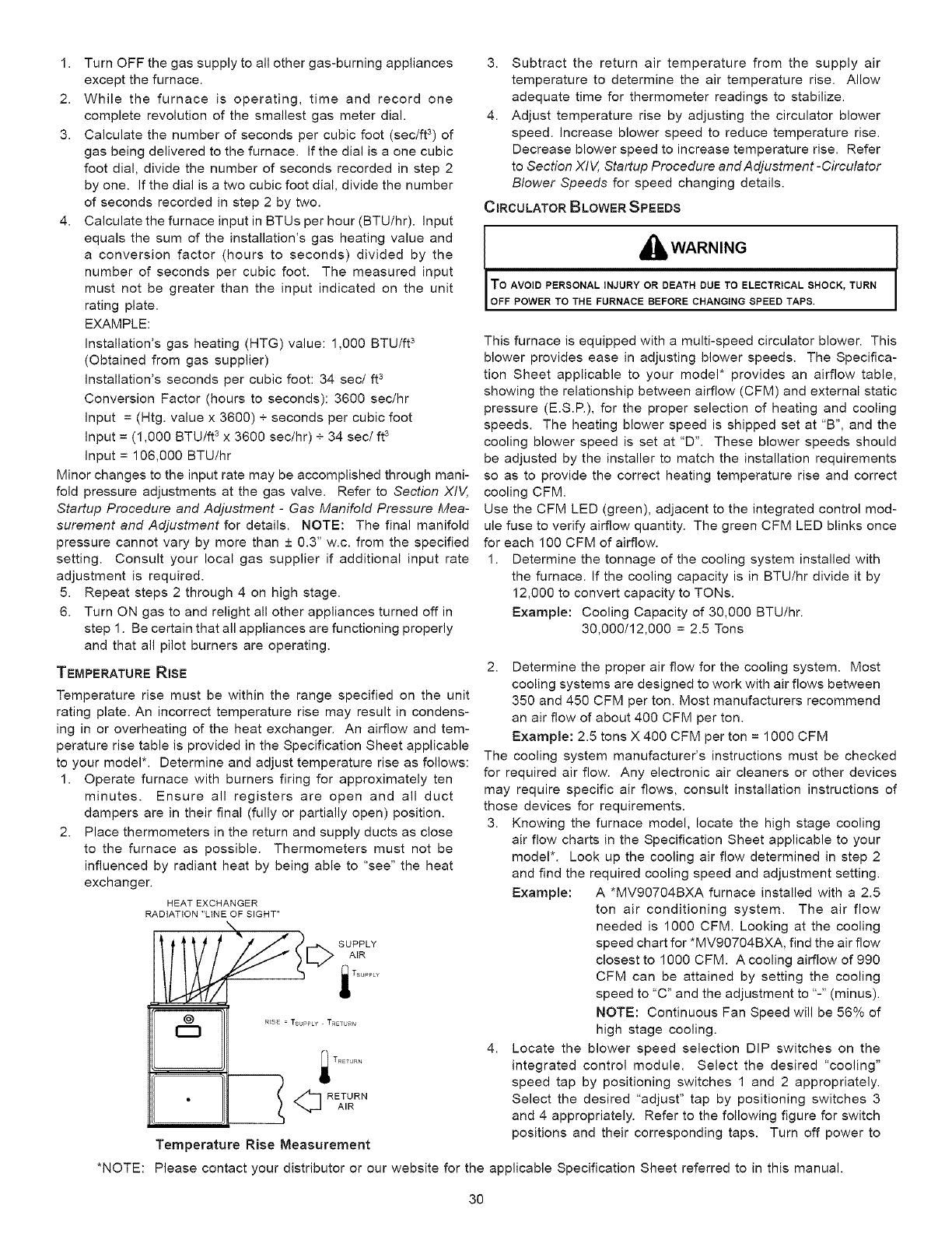
1. Turn OFF the gas supply to all other gas-burning appliances
except the furnace.
2. While the furnace is operating, time and record one
complete revolution of the smallest gas meter dial.
3. Calculate the number of seconds per cubic foot (sec/ft 3) of
gas being delivered to the furnace. If the dial is a one cubic
foot dial, divide the number of seconds recorded in step 2
by one. If the dial is a two cubic foot dial, divide the number
of seconds recorded in step 2 by two.
4. Calculate the furnace input in BTUs per hour (BTU/hr). Input
equals the sum of the installation's gas heating value and
a conversion factor (hours to seconds) divided by the
number of seconds per cubic foot. The measured input
must not be greater than the input indicated on the unit
rating plate.
EXAMPLE:
Installation's gas heating (HTG) value: 1,000 BTU/ft 3
(Obtained from gas supplier)
Installation's seconds per cubic foot: 34 sec/ft 3
Conversion Factor (hours to seconds): 3600 sec/hr
Input = (Htg. value x 3600) + seconds per cubic foot
Input = (1,000 BTU/ft 3 x 3600 sec/hr) + 34 sec/ft 3
Input = 106,000 BTU/hr
Minor changes to the input rate may be accomplished through mani-
fold pressure adjustments at the gas valve. Refer to Section )(IV,
Startup Procedure and Adjustment -Gas Manifold Pressure Mea-
surement and Adjustment for details. NOTE: The final manifold
pressure cannot vary by more than + 0.3" w.c. from the specified
setting. Consult your local gas supplier if additional input rate
adjustment is required.
5. Repeat steps 2 through 4 on high stage.
6. Turn ON gas to and relight all other appliances turned off in
step 1. Be certain that all appliances are functioning properly
and that all pilot burners are operating.
TEMPERATURE RISE
Temperature rise must be within the range specified on the unit
rating plate. An incorrect temperature rise may result in condens-
ing in or overheating of the heat exchanger. An airflow and tem-
perature rise table is provided in the Specification Sheet applicable
to your model*. Determine and adjust temperature rise as follows:
1. Operate furnace with burners firing for approximately ten
minutes. Ensure all registers are open and all duct
dampers are in their final (fully or partially open) position.
2. Place thermometers in the return and supply ducts as close
to the furnace as possible. Thermometers must not be
influenced by radiant heat by being able to "see" the heat
exchanger.
HEAT EXCHANGER
RADiATiON "LINE OF SIGHT"
N
@R_SE = TsuPPty TR_TURN
__ <_ RETURN
AIR
Temperature Rise Measurement
3. Subtract the return air temperature from the supply air
temperature to determine the air temperature rise. Allow
adequate time for thermometer readings to stabilize.
4. Adjust temperature rise by adjusting the circulator blower
speed. Increase blower speed to reduce temperature rise.
Decrease blower speed to increase temperature rise. Refer
to Section )(IV, Startup Procedure and Adjustment -Circulator
Blower Speeds for speed changing details.
CIRCULATOR BLOWER SPEEDS
I a.WAR.,.G
To AVOID PERSONAL INJURY OR DEATH DUE TO ELECTRICAL SHOCK, TURN
[ OFF POWER TO THE FURNACE BEFORE CHANG NG SPEED TAPS,
This furnace is equipped with a multi-speed circulator blower. This
blower provides ease in adjusting blower speeds. The Specifica-
tion Sheet applicable to your model* provides an airflow table,
showing the relationship between airflow (CFM) and external static
pressure (E.S.R), for the proper selection of heating and cooling
speeds. The heating blower speed is shipped set at "B", and the
cooling blower speed is set at "D". These blower speeds should
be adjusted by the installer to match the installation requirements
so as to provide the correct heating temperature rise and correct
cooling CFM.
Use the CFM LED (green), adjacent to the integrated control mod-
ule fuse to verify airflow quantity. The green CFM LED blinks once
for each 100 CFM of airflow.
1. Determine the tonnage of the cooling system installed with
the furnace. If the cooling capacity is in BTU/hr divide it by
12,000 to convert capacity to TONs.
Example: Cooling Capacity of 30,000 BTU/hr.
30,000/12,000 = 2.5 Tons
2. Determine the proper air flow for the cooling system. Most
cooling systems are designed to work with air flows between
350 and 450 CFM per ton. Most manufacturers recommend
an air flow of about 400 CFM per ton.
Example: 2.5 tons X 400 CFM per ton = 1000 CFM
The cooling system manufacturer's instructions must be checked
for required air flow. Any electronic air cleaners or other devices
may require specific air flows, consult installation instructions of
those devices for requirements.
3. Knowing the furnace model, locate the high stage cooling
air flow charts in the Specification Sheet applicable to your
model*. Look up the cooling air flow determined in step 2
and find the required cooling speed and adjustment setting.
Example: A *MV90704BXA furnace installed with a 2.5
ton air conditioning system. The air flow
needed is 1000 CFM. Looking at the cooling
speed chart for *MV90704BXA, find the air flow
closest to 1000 CFM. A cooling airflow of 990
CFM can be attained by setting the cooling
speed to "C" and the adjustment to "-" (minus).
NOTE: Continuous Fan Speed will be 56% of
high stage cooling.
4. Locate the blower speed selection DIP switches on the
integrated control module. Select the desired "cooling"
speed tap by positioning switches 1 and 2 appropriately.
Select the desired "adjust" tap by positioning switches 3
and 4 appropriately. Refer to the following figure for switch
positions and their corresponding taps. Turn off power to
*NOTE: Please contact your distributor or our website for the applicable Specification Sheet referred to in this manual.
30
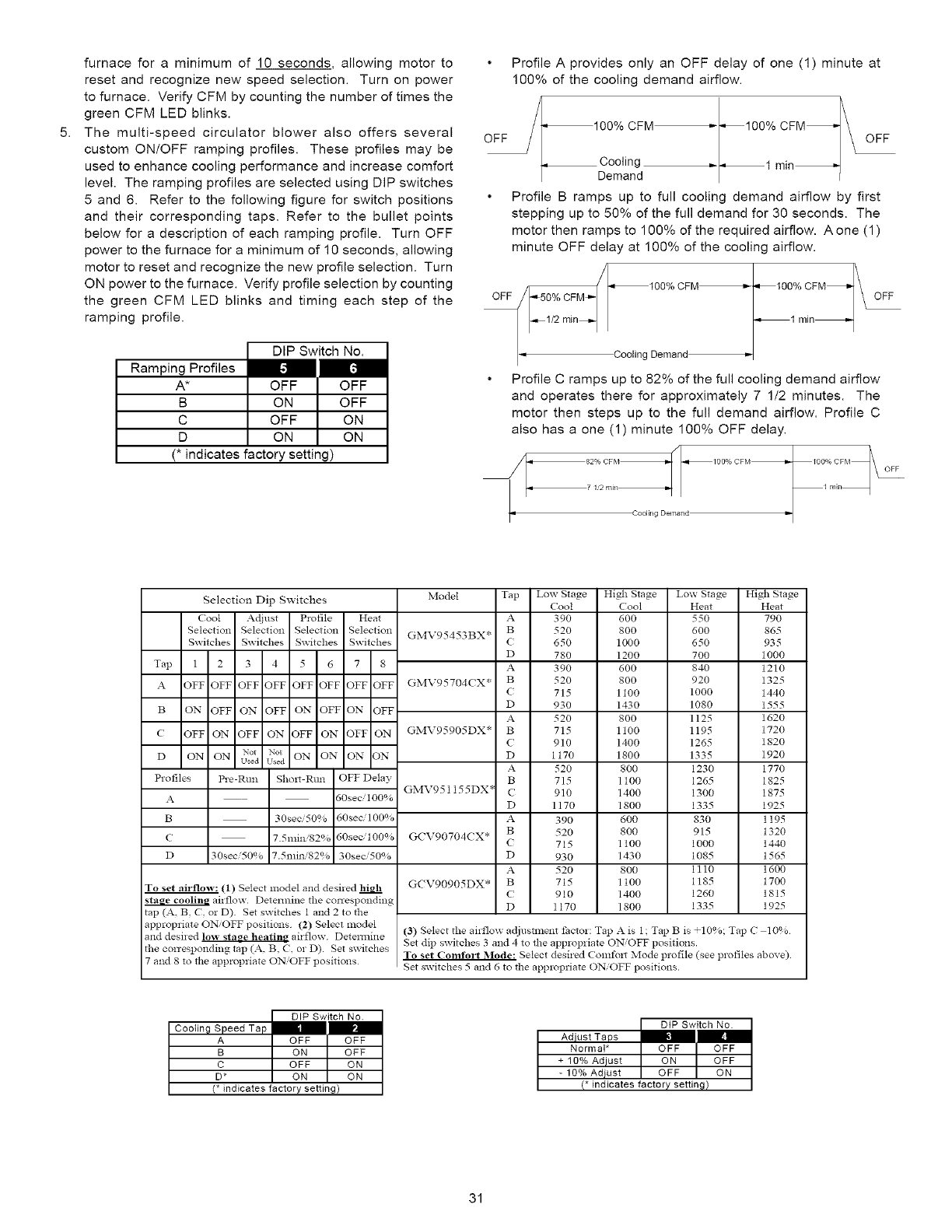
5.
furnace for a minimum of 10 seconds, allowing motor to
reset and recognize new speed selection. Turn on power
to furnace. Verify CFM by counting the number of times the
green CFM LED blinks.
The multi-speed circulator blower also offers several
custom ON/OFF ramping profiles. These profiles may be
used to enhance cooling performance and increase comfort
level. The ramping profiles are selected using DIP switches
5 and 6. Refer to the following figure for switch positions
and their corresponding taps. Refer to the bullet points
below for a description of each ramping profile. Turn OFF
power to the furnace for a minimum of 10 seconds, allowing
motor to reset and recognize the new profile selection. Turn
ON power to the furnace. Verify profile selection by counting
the green CFM LED blinks and timing each step of the
ramping profile.
DIP Switch No.
Ramping Profiles
A* OFF
B ON
C OFF
D ON
(* indicates factory setting)
[.1
OFF
OFF
ON
ON
Profile A provides only an OFF delay of one (1) minute at
100% of the cooling demand airflow.
Oq100% CFM_t_100% CFM_ _FFOFF
Cooling ,-_1 min_
Demand I
Profile B ramps up to full cooling demand airflow by first
stepping up to 50% of the full demand for 30 seconds. The
motor then ramps to 100% of the required airflow. A one (1)
minute OFF delay at 100% of the cooling airflow.
_100% CFM _-_ 100%CFM_
OFF '_50% CFM_'-
_1/2 min_ _1 min_
CoolingDemand_
Profile C ramps up to 82% of the full cooling demand airflow
and operates there for approximately 7 1/2 minutes. The
motor then steps up to the full demand airflow. Profile C
also has a one (1) minute 100% OFF delay.
OFF
Cooling Demand
Selection Dip Switches
Cool Acliust Profile Heat
Selection Selection Selection Selection
Switches Switches Switches Switches
Tap 1 2 3 4 5 6 7 8
A OFF OFF OFF OFF OFF OFF OFF OFF
B ON OFF ON OFF ON OFF ON OFF
( OFF ON OFF ON OFF ON OFF ON
Not Not
D ON ON u_a u_*a ON ON ON ON
Profiles Pre-Rtm Shox_-Rtm OFF Delay
A 50seci100%
B 30see 50% 60see/100%
C 7.5mini82% 50sec,'100%
D 30see/50% 7.5mini82qa 30seci50%
To set airflow: (1) Select model and desired
aixflow. Determine the conespondmg
tap (A. B. (. or D) Set switches 1 and 2 to the
appropriate ONOFF positions (2) Select model
and desired low stase he_tins airflow. Detemline
the conesponding tap (A, B, C, or D). Set switches
7 and 8 to the appropriate ON/OFF positions
Model
GMV95453BX*
GMV95704CX* (
D
A
GMV95905DX* B
C
D
A
B
GMV951155DX* C
D
A
B
GCV90704CX* C
D
A
G(V90905DX* B
(
D
Tap Low Stage
Coot
A 390
B 520
C 650
D 780
A 390
B 520
715
930
52O
715
910
1170
52O
715
910
1170
390
520
715
930
520
715
910
1170
High Stage
Cool
600
800
1000
1200
600
800
1100
1430
800
1100
1400
1800
800
1100
1400
1800
6O0
8OO
1100
1430
800
1t00
1400
1800
Low Stage
Heat
55O
600
650
700
840
920
1000
1080
1125
1195
1265
1335
1230
1265
1300
1335
83O
915
1000
1085
1110
1185
1260
1335
High Stage
Heat
79O
865
935
1000
1210
1325
1440
1555
1620
1720
1820
1920
1770
1825
1875
1925
1195
1320
1440
1565
1600
1700
1815
1925
(3) Select the airflow adjustment t:actor: Tap A is 1 ; Tap B is _10%; Tap C 10%
Set dip switches 3 and 4 to the appropriate ON'OFF positions.
To set Comfort M_le: Select desired Comtbl_ Mode profile (see profiles above).
Set switches 5 and 6 to the appl_priate ON/OFF positions.
DIP Switch No.
Cooling Speed Tap _
A OFF OFF
B ON QFF
C QFF ON
D* ON ON
(* indicates factory setting)
DtP Switch No.
Adiust Taps _-
Normal* OFF OFF
+ 10% Adjust ON OFF
- 10% Adiust QFF QN
(* indicates factory setting)
31
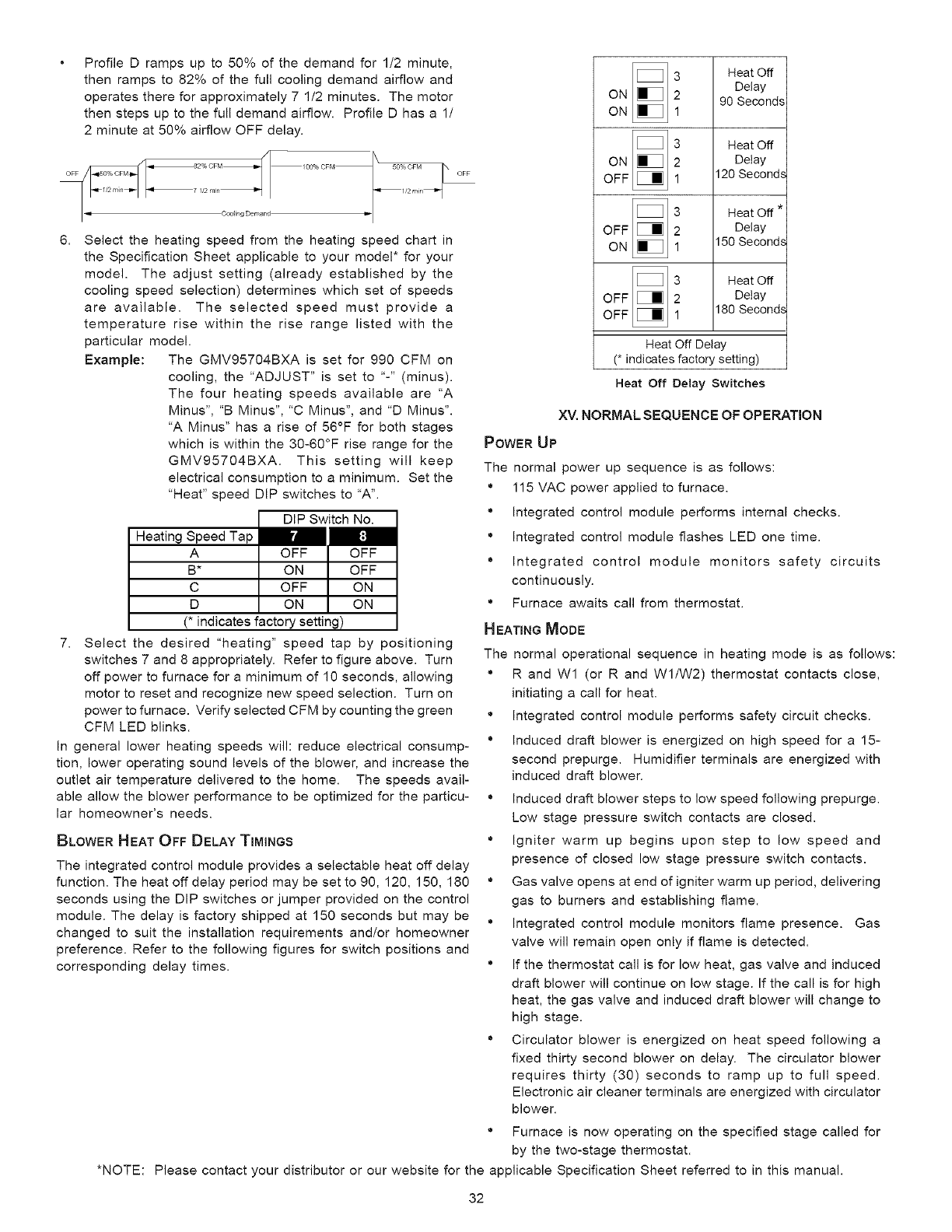
6.
Profile D ramps up to 50% of the demand for 1/2 minute,
then ramps to 82% of the full cooling demand airflow and
operates there for approximately 7 1/2 minutes. The motor
then steps up to the full demand airflow. Profile D has a 1/
2 minute at 50% airflow OFF delay.
/00% CFM 50% CFM OFF
Select the heating speed from the heating speed chart in
the Specification Sheet applicable to your model* for your
model. The adjust setting (already established by the
cooling speed selection) determines which set of speeds
are available. The selected speed must provide a
temperature rise within the rise range listed with the
particular model.
Example: The GMV95704BXA is set for 990 CFM on
cooling, the "ADJUST" is set to "-" (minus).
The four heating speeds available are "A
Minus", "B Minus", "C Minus", and "D Minus".
"A Minus" has a rise of 56°F for both stages
which is within the 30-60°F rise range for the
GMV95704BXA. This setting will keep
electrical consumption to a minimum. Set the
"Heat" speed DIP switches to "A".
Heating Speed Tap
A
B*
C
D
DIP Switch No.
IrA [:!
OFF OFF
ON OFF
OFF ON
ON ON
(* indicates factory setting)
7. Select the desired "heating" speed tap by positioning
switches 7 and 8 appropriately. Refer to figure above. Turn
off power to furnace for a minimum of 10 seconds, allowing
motor to reset and recognize new speed selection. Turn on
power to furnace. Verify selected CFM by counting the green
CFM LED blinks.
In general lower heating speeds will: reduce electrical consump-
tion, lower operating sound levels of the blower, and increase the
outlet air temperature delivered to the home. The speeds avail-
able allow the blower performance to be optimized for the particu-
lar homeowner's needs.
BLOWER HEAT OFF DELAY TiMiNGS
The integrated control module provides a selectable heat off delay
function. The heat off delay period may be set to 90, 120, 150, 180
seconds using the DIP switches or jumper provided on the control
module. The delay is factory shipped at 150 seconds but may be
changed to suit the installation requirements and/or homeowner
preference. Refer to the following figures for switch positions and
corresponding delay times.
*NOTE:
ON _!_
ON _!_
ON
OFF 1
3
OFF [J_ 2
ON 1
3 Heat Off
Delay
2 90 Seconds
1
3 Heat Off
2 Delay
120 Seconds
Heat Off *
Delay
150 Seconds
_i Heat Off
OFF Delay
OFF 180 Seconds
Heat Off Delay
(* indicates factory setting)
Heat Off Delay Switches
XV, NORMAL SEQUENCE OF OPERATION
POWER UP
The normal power up sequence is as follows:
• 115 VAC power applied to furnace.
'_ Integrated control module performs internal checks.
° Integrated control module flashes LED one time.
'_ Integrated control module monitors safety circuits
continuously.
° Furnace awaits call from thermostat.
HEATING MODE
The normal operational sequence in heating mode is as follows:
'_ R and W1 (or R and WI/W2) thermostat contacts close,
initiating a call for heat.
° Integrated control module performs safety circuit checks.
'_ Induced draft blower is energized on high speed for a 15-
second prepurge. Humidifier terminals are energized with
induced draft blower.
'_ Induced draft blower steps to low speed following prepurge.
Low stage pressure switch contacts are closed.
° Igniter warm up begins upon step to low speed and
presence of closed low stage pressure switch contacts.
° Gas valve opens at end of igniter warm up period, delivering
gas to burners and establishing flame.
'_ Integrated control module monitors flame presence. Gas
valve will remain open only if flame is detected.
• If the thermostat call is for low heat, gas valve and induced
draft blower will continue on low stage. If the call is for high
heat, the gas valve and induced draft blower will change to
high stage.
'_ Circulator blower is energized on heat speed following a
fixed thirty second blower on delay. The circulator blower
requires thirty (30) seconds to ramp up to full speed.
Electronic air cleaner terminals are energized with circulator
blower.
° Furnace is now operating on the specified stage called for
by the two-stage thermostat.
Please contact your distributor or our website for the applicable Specification Sheet referred to in this manual.
32
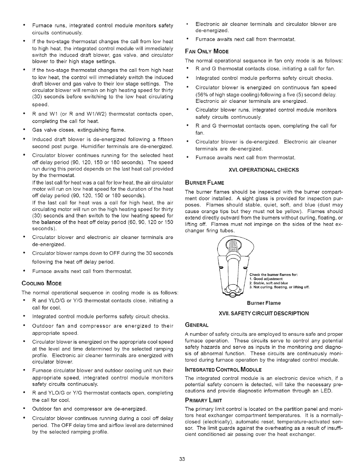
" Furnace runs, integrated control module monitors safety
circuits continuously.
° If the two-stage thermostat changes the call from low heat
to high heat, the integrated control module will immediately
switch the induced draft blower, gas valve, and circulator
blower to their high stage settings.
" If the two-stage thermostat changes the call from high heat
to low heat, the control will immediately switch the induced
draft blower and gas valve to their low stage settings. The
circulator blower will remain on high heating speed for thirty
(30) seconds before switching to the low heat circulating
speed.
° R and W1 (or R and WI/W2) thermostat contacts open,
completing the call for heat.
" Gas valve closes, extinguishing flame.
° Induced draft blower is de-energized following a fifteen
second post purge. Humidifier terminals are de-energized.
" Circulator blower continues running for the selected heat
off delay period (90, 120, 150 or 180 seconds). The speed
run during this period depends on the last heat call provided
by the thermostat.
If the last call for heat was a call for low heat, the air circulator
motor will run on low heat speed for the duration of the heat
off delay period (90, 120, 150 or 180 seconds).
If the last call for heat was a call for high heat, the air
circulating motor will run on the high heating speed for thirty
(30) seconds and then switch to the low heating speed for
the balance of the heat off delay period (60, 90, 120 or 150
seconds).
" Circulator blower and electronic air cleaner terminals are
de-energized.
° Circulator blower ramps down to OFF during the 30 seconds
following the heat off delay period.
" Furnace awaits next call from thermostat.
COOLING MODE
The normal operational sequence in cooling mode is as follows:
° R and YLO/G or Y/G thermostat contacts close, initiating a
call for cool.
° Integrated control module performs safety circuit checks.
" Outdoor fan and compressor are energized to their
appropriate speed.
° Circulator blower is energized on the appropriate cool speed
at the level and time determined by the selected ramping
profile. Electronic air cleaner terminals are energized with
circulator blower.
" Furnace circulator blower and outdoor cooling unit run their
appropriate speed, integrated control module monitors
safety circuits continuously.
" R and YLO/G or Y/G thermostat contacts open, completing
the call for cool.
° Outdoor fan and compressor are de-energized.
" Circulator blower continues running during a cool off delay
period. The OFF delay time and airflow level are determined
by the selected ramping profile.
Electronic air cleaner terminals and circulator blower are
de-energized.
" Furnace awaits next call from thermostat.
FAN ONLY MODE
The normal operational sequence in fan only mode is as follows:
" R and G thermostat contacts close, initiating a call for fan.
" Integrated control module performs safety circuit checks.
" Circulator blower is energized on continuous fan speed
(56% of high stage cooling) following a five (5) second delay.
Electronic air cleaner terminals are energized.
" Circulator blower runs, integrated control module monitors
safety circuits continuously.
" R and G thermostat contacts open, completing the call for
fan.
° Circulator blower is de-energized. Electronic air cleaner
terminals are de-energized.
° Furnace awaits next call from thermostat.
XVl. OPERATIONAL CHECKS
BURNER FLAME
The burner flames should be inspected with the burner compart-
ment door installed. A sight glass is provided for inspection pur-
poses. Flames should stable, quiet, soft, and blue (dust may
cause orange tips but they must not be yellow). Flames should
extend directly outward from the burners without curling, floating, or
lifting off. Flames must not impinge on the sides of the heat ex-
changer firing tubes.
Check the burner flames for:
1. Good adjustment
2. Stable, soft and blue
3. Not curling, floating, or lifting off.
Burner Flame
XVIL SAFETY CIRCUIT DESCRIPTION
GENERAL
A number of safety circuits are employed to ensure safe and proper
furnace operation. These circuits serve to control any potential
safety hazards and serve as inputs in the monitoring and diagno-
sis of abnormal function. These circuits are continuously moni-
tored during furnace operation by the integrated control module.
_NTEGRATED CONTROL MODULE
The integrated control module is an electronic device which, if a
potential safety concern is detected, will take the necessary pre-
cautions and provide diagnostic information through an LED.
PRIMARY LIMIT
The primary limit control is located on the partition panel and moni-
tors heat exchanger compartment temperatures. It is a normally-
closed (electrically), automatic reset, temperature-activated sen-
sor. The limit guards against the overheating as a result of insuffi-
cient conditioned air passing over the heat exchanger.
33
AUXILIARY LIMIT
The auxiliary limit controls are located on or near the circulator
blower and monitors blower compartment temperatures. They are
a normally-closed (electrically), manual-reset sensors. These lim-
its guard against overheating as a result of insufficient conditioned
air passing over the heat exchanger.
ROLLOUTLIMIT
The rollout limit controls are mounted on the burner/manifold as-
sembly and monitor the burner flame. They are normally-closed
(electrically), manual-reset sensors. These limits guard against
burner flames not being properly drawn into the heat exchanger.
PRESSURE SWITCHES
The pressure switches are normally-open (closed during opera-
tion) negative air pressure-activated switches. They monitor the
airflow (combustion air and flue products) through the heat ex-
changer via pressure taps located on the induced draft blower and
the coil front cover. These switches guard against insufficient air-
flow (combustion air and flue products) through the heat exchanger
and/or blocked condensate drain conditions.
FLAME SENSOR
The flame sensor is a probe mounted to the burner/manifold as-
sembly which uses the principle of flame rectification to determine
the presence or absence of flame.
XVIII. TROUBLESHOOTING
ELECTROSTATIC DISCHARGE (ESD) PRECAUTIONS
NOTE: Discharge body's static electricity before touching unit. An
electrostatic discharge can adversely affect electrical components.
Use the following precautions during furnace installation and ser-
vicing to protect the integrated control module from damage. By
putting the furnace, the control, and the person at the same electro-
static potential, these steps will help avoid exposing the integrated
control module to electrostatic discharge. This procedure is appli-
cable to both installed and uninstalled (ungrounded) furnaces.
1. Disconnect all power to the furnace. Do not touch the
integrated control module or any wire connected to the control
prior to discharging your body's electrostatic charge to
ground.
2. Firmly touch a clean, unpainted, metal surface of the
furnaces near the control. Any tools held in a person's
hand during grounding will be discharged.
3. Service integrated control module or connecting wiring
following the discharge process in step 2. Use caution not
to recharge your body with static electricity; (i.e., do not move
or shuffle your feet, do not touch ungrounded objects, etc.).
If you come in contact with an ungrounded object, repeat
step 2 before touching control or wires.
4. Discharge your body to ground before removing a new
control from its container. Follow steps 1 through 3 if
installing the control on a furnace. Return any old or new
controls to their containers before touching any ungrounded
object.
DIAGNOSTIC CHART
,_, WARNING
HIGH VOLTAGE! _ _i_
To AVOID PERSONAL INJURY OR DEATH DUE TO
ELECTRICAL SHOCK_ DISCONNECT ELECTRICAL POWER
BEFORE PERFORMAING ANY SERVICE OR MAINTENANCE.
Refer to the Troubleshooting Chart at the end of this manual for
assistance in determining the source of unit operational problems.
The red diagnostic LED blinks to assist in troubleshooting the unit.
The number of blinks refers to a specific fault code.
RESETTING FROM LOCKOUT
Furnace lockout results when a furnace is unable to achieve igni-
tion after three attempts. It is characterized by a non-functioning
furnace and a one flash diagnostic LED code. If the furnace is in
"lockout", it will (or can be) reset in any of the following ways.
1. Automatic reset. The integrated control module will
automatically reset itself and attempt to resume normal
operations following a one hour lockout period.
2. Manual power interruption. Interrupt 115 volt power to the
furnace for 1 - 20 seconds.
3. Manual thermostat cycle. Lower the thermostat so that
there is no longer a call for heat then reset to previous setting.
Interrupt thermostat signal to the furnace for 1 -20 seconds.
NOTE: If the condition which originally caused the lockout still
exists, the control will return to lockout. Refer to Section >(VIII,
Troubleshooting -Diagnostic Chart for aid in determining the cause.
XIX. MAINTENANCE
_WARNING
HIGH VOLTAGE!
To AVOID PERSONAL INJURY OR DEATH DUE TO
ELECTRICAL SHOCK, DISCONNECT ELECTRICAL POWER _
BEFORE PERFORMING ANY MAINTENANCE, IF YOU MUST
HANDLE THE IGNITER, HANDLE WITH CARE, TOUCHING
THE IGNITER ELEMENT WITH BARE FINGERS, ROUGH
HANDLING OR VIBRATION COULD DAMAGE THE IGNITER
RESULTING IN PREMATURE FAILURE, ONLY A QUALIFIED
SERVICER SHOULD EVER HANDLE THE IGNITER.
ANNUAL INSPECTION
The furnace should be inspected by a qualified installer, or service
agency at least once per year. This check should be performed at
the beginning of the heating season. This will ensure that all fur-
nace components are in proper working order and that the heating
system functions appropriately. Pay particular attention to the fol-
lowing items. Repair or service as necessary.
• Flue pipe system. Check for blockage and/or leakage. Check
the outside termination and the connections at and internal
to the furnace.
" Heat exchanger. Check for corrosion and/or buildup within
the heat exchanger passageways.
• Burners. Check for proper ignition, burner flame, and flame
sense.
• Drainage system. Check for blockage and/or leakage.
Check hose connections at and internal to furnace.
" Wiring. Check electrical connections for tightness and/or
corrosion. Check wires for damage.
" Filters.
34
FILTERS
,_ CAUTION
To ENSURE PROPER UNIT PERFORMANCE, ADHERE TO THE FILTER
SIZES GIVEN IN THE RECOMMENDED MINIMUM FILTER SIZE TABLE OR
SPECIFICATION SHEET APPLICABLE TO YOUR MODEL*
MAINTENANCE
Improper filter maintenance is the most common cause of inad-
equate heating or cooling performance. Filters should be cleaned
(permanent) or replaced (disposable) every two months or as re-
quired. When replacing a filter, it must be replaced with a filter of
the same type and size.
FILTER REMOVAL
Depending on the installation, differing filter arrangements can be
applied. Filters can be installed in either the central return register
or a side panel external filter rack (upflow only). A media air filter or
electronic air cleaner can be used as an alternate filter. Follow the
filter sizes given in the Recommended Minimum Filter size table to
ensure proper unit performance.
To remove filters from an external filter rack in an upright upflow
installation, follow the directions provided with external filter rack
kit. To remove internal filters see Internal Filter Removal section.
Internal filters are an accessory item and are not included with
your furnace. For further details, see your distributor.
HORIZONTAL UNIT FILTER REMOVAL
Filters in horizontal installations are located in the central return
register or the ductwork near the furnace.
To remove:
1. Turn OFF electrical power to furnace.
2. Remove filter(s) from the central return register or ductwork.
3. Replace filter(s) by reversing the procedure for removal.
4. Turn ON electrical power to furnace.
MEDIA AIR FILTER OR ELECTRONIC AIR CLEANER REMOVAL
Follow the manufacturer's directions for service.
BURNERS
Visually inspect the burner flames periodically during the heating
season. Turn on the furnace at the thermostat and allow several
minutes for flames to stabilize, since any dislodged dust will alter
the flames normal appearance. Flames should be stable, quiet,
soft, and blue (dust may cause orange tips but they must not be
yellow). They should extend directly outward from the burners with-
out curling, floating, or lifting off. Flames must not impinge on the
sides of the heat exchanger firing tubes.
INDUCED DRAFT AND CIRCULATOR BLOWERS
The bearings in the induced draft blower and circulator blower
motors are permanently lubricated by the manufacturer. No further
lubrication is required. Check motor windings for accumulation of
dust which may cause overheating. Clean as necessary.
CONDENSATE TRAP AND BRAIN SYSTEM (QUALIFIED SERVICER
ONLY)
Annually inspect the drain tubes, drain trap, and field-supplied drain
line for proper condensate drainage. Check drain system for hose
connection tightness, blockage, and leaks. Clean or repair as
necessary.
FLAME SENSOR (QUALIFIED SERVICER ONLY)
Under some conditions, the fuel or air supply can create a nearly
invisible coating on the flame sensor. This coating acts as an
insulator causing a drop in the flame sense signal. If the flame
sense signal drops too low the furnace will not sense flame and
will lock out. The flame sensor should be carefully cleaned by a
qualified servicer using emery cloth or steel wool. Following clean-
ing, the flame sense signal should be as indicated in the Specifi-
cations Sheet.
FLUE PASSAGES (QUALIFIED SERVICER ONLY)
The heat exchanger flue passageways should be inspected at the
beginning of each heating season. If necessary, clean the pas-
sageways as outlined below.
1. Turn OFF the electrical power and gas supply to the furnace.
2. Disconnect the gas line and remove the burner/ manifold
assembly by removing the screws securing the assembly
to the partition panel.
3. Disconnect the flue pipe system from the induced draft
blower.
4. Remove the induced draft blower and, drain and pressure
tap hoses from the recuperator coil front cover.
5. Remove the recuperator coil front cover to expose the coil
tubes and turbulators.
6. Remove the recuperator coil turbulators individually by slowly
pulling each turbulator forward firmly.
7. Clean the recuperator coil tubes using a long handle wire
brush, such as a gun cleaning brush.
8. Clean the primary heat exchanger tubes using a wire brush
attached to a length of high grade stainless steel cable,
such as drain cleanout cable. Attach a variable speed
reversible drill to the other end of the cable. Slowly rotate
the cable with the drill and insert it into one of the heat
exchanger tubes. While reversing the drill, work the cable
in and out several times to obtain sufficient cleaning. Repeat
for each tube.
9. Clean residue from furnace using a vacuum cleaner.
10. Replace the parts removed in the previous steps in reverse
order.
11. Turn on electrical power and gas to furnace. Check for
leaks and proper unit operation.
12. Severe heat exchanger fouling is an indication of an
operational problem. Perform the checks listed in Section
>(IV, Startup Procedure and Adjustments to reduce the
chances of repeated fouling.
XX. INTERNAL FILTER REMOVAL
Internal filters are an accessory item and are not included with your
furnace. For further details, see your distributor.
BOTTOM RETURN REMOVAL
1. Turn OFF electrical power to furnace.
2. Remove blower compartment door,
3. Push back and up on the wire filter retainer to release it
from under the front lip of the furnace basepan.
4. Slide filter forward and out.
5. Replace filter by reversing the procedure.
BLOWER COMPARTMENT REMOVAL
1. Turn OFF electrical power to furnace.
2. Remove blower compartment door.
*NOTE: Please contact your distributor or our website for the applicable Specification Sheet referred to in this manual.
35
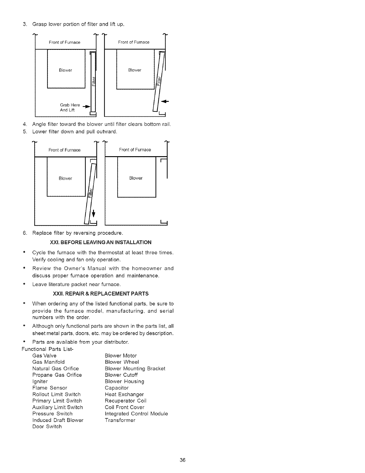
3. Grasp lower portion of filter and lift up.
Front of Furnace
Blower
Grab Here
And Lift
Front of Furnace
4. Angle filter toward the blower until filter clears bottom rail.
5. Lower filter down and pull outward.
Front of Furnace
Blower
Front of Furnace
Blower
6. Replace filter by reversing procedure.
XXL BEFORE LEAVINGAN INSTALLATION
• Cycle the furnace with the thermostat at least three times.
Verify cooling and fan only operation.
• Review the Owner's Manual with the homeowner and
discuss proper furnace operation and maintenance.
• Leave literature packet near furnace.
XXIL REPAIR & REPLACEMENT PARTS
" When ordering any of the listed functional parts, be sure to
provide the furnace model, manufacturing, and serial
numbers with the order.
" Although only functional parts are shown in the parts list, all
sheet metal parts, doors, etc. may be ordered by description.
Parts are available from your distributor.
o
Functional Parts List-
Gas Valve
Gas Manifold
Natural Gas Orifice
Propane Gas Orifice
Igniter
Flame Sensor
Rollout Limit Switch
Primary Limit Switch
Auxiliary Limit Switch
Pressure Switch
Induced Draft Blower
Door Switch
Blower Motor
Blower Wheel
Blower Mounting Bracket
Blower Cutoff
Blower Housing
Capacitor
Heat Exchanger
Recuperator Coil
Coil Front Cover
Integrated Control Module
Transformer
36
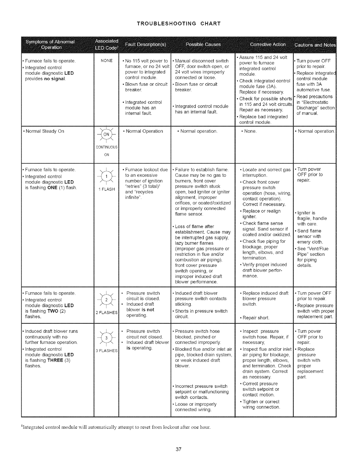
TROUBLESHOOTINGCHART
,Furnace fails to operate.
,Integrated control
module diagnostic LED
provides no signal.
• Normal Steady On
, Furnace fails to operate.
, Integrated control
module diagnostic LED
is flashing ONE (1) flash.
, Furnace fails to operate.
, Integrated control
module diagnostic LED
is flashing TWO (2)
flashes.
, Induced draft blower runs
continuously with no
further furnace operation.
, Integrated control
module diagnostic LED
is flashing THREE (3)
flashes.
E
NONE
CONTINUOUS
ON
1 FLASH
12 FLASHES
3 FLASHES
°No 115 volt power to
furnace, or no 24 volt
power to integrated
control module.
*Blown fuse or circuit
breaker.
*Integrated control
module has an
internal fault.
• Normal Operation
*Furnace lockout due
to an excessive
number of ignition
"retries" (3 total) _
and "recycles
infinite".
• Pressure switch
circuit is closed.
• Induced draft
blower is not
operating.
• Pressure switch
circuit not closed.
• Induced draft blower
is operating.
• Manual disconnect switch
OFF, door switch open, or
24 volt wires improperly
connected or loose.
• Blown fuse or circuit
breaker.
• Integrated control module
has an internal fault.
°Normal operation.
• Failure to establish flame.
Cause may be no gas to
burners, front cover
pressure switch stuck
open, bad igniter or igniter
alignment, improper
orifices, or coated/oxidized
or improperly connected
flame sensor.
• Loss of flame after
establishment. Cause may
be interrupted gas supply,
lazy burner flames
(improper gas pressure or
restriction in flue and/or
combustion air piping),
front cover pressure
switch opening, or
improper induced draft
blower performance.
• Induced draft blower
pressure switch contacts
sticking.
• Shorts in pressure switch
circuit.
• Pressure switch hose
blocked, pinched or
connected improperly.
• Blocked flue and/or inlet air
pipe, blocked drain system,
or weak induced draft
blower.
• Incorrect pressure switch
setpoint or malfunctioning
switch contacts.
• Loose or improperly
connected wiring.
• Assure 115 and 24 volt
power to furnace
integrated control
module.
• Check integrated control
module fuse (3A).
Replace if necessary.
• Check for possible shorts
in 115 and 24 volt circuits
Repair as necessary.
• Replace bad integrated
control module.
• None.
• Locate and correct gas
interruption.
• Check front cover
pressure switch
operation (hose, wiring,
contact operation).
Correct if necessary.
• Replace or realign
igniter.
• Check flame sense
signal. Sand sensor if
coated and/or oxidized.
• Check flue piping for
blockage, proper
length, elbows, and
termination.
• Verify proper induced
draft blower perfor-
mance.
• Replace induced draft
blower pressure
switch.
• Repair short.
• Inspect pressure
switch hose. Repair, if
necessary,
• Inspect flue and/or inlet
air piping for blockage,
proper length, elbows,
and termination. Check
drain system. Correct
as necessary.
• Correct pressure
switch setpoint or
contact motion.
• Tighten or correct
wiring connection.
, Turn power OFF
prior to repair.
, Replace integratec
control module
fuse with 3A
automotive fuse.
, Read precautions
in "Electrostatic
Discharge" section
of manual.
*Normal operation.
*Turn power
OFF prior to
repair.
*Igniter is
fragile, handle
with care.
. Sand flame
sensor with
emery cloth.
See "Vent/Flue
Pipe" section
for piping
details.
*Turn power OFF
prior to repair.
*Replace pressure
switch with proper
replacement part.
• Turn power
OFF prior to
repair.
• Replace
pressure
switch with
proper
replacement
part.
1Integrated control module will automatically attempt to reset fi'om lockout after one hour.
37
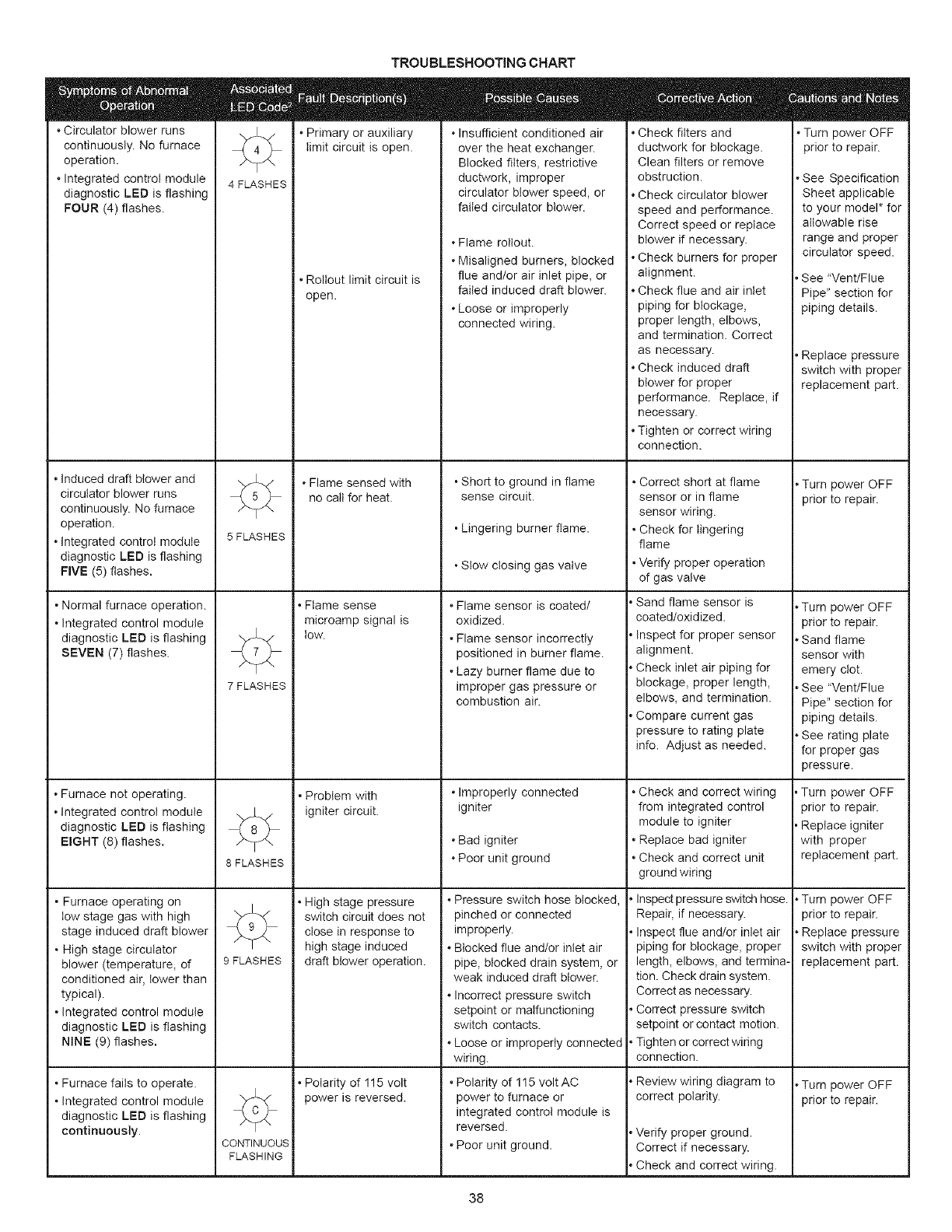
*Circulator blower runs
continuously. No furnace
operation.
.Integrated control module
diagnostic LED is flashing
FOUR (4) flashes.
• Induced draft blower and
circulator blower runs
continuously. No furnace
operation.
• Integrated control module
diagnostic LED is flashing
FIVE (5) flashes.
• Normal furnace operation.
• Integrated control module
diagnostic LED is flashing
SEVEN (7) flashes.
• Furnace not operating.
• Integrated control module
diagnostic LED is flashing
EIGHT (8) flashes.
• Furnace operating on
tow stage gas with high
stage induced draft blower
• High stage circulator
blower (temperature, of
conditioned air, lower than
typical).
• Integrated control module
diagnostic LED is flashing
NiNE (9) flashes.
• Furnace fails to operate.
• Integrated control module
diagnostic LED is flashing
continuously.
TROUBLESHOOTING CHART
°Primary or auxiliary °Insufficient conditioned air
limit circuit is open. over the heat exchanger.
4 FLASHES
• Roltout limit circuit is
Blocked filters, restrictive
ductwork, improper
circulator blower speed, or
failed circulator blower.
°Flame roltout.
°Misaligned burners, blocked
flue and/or air inlet pipe, or
failed induced draft blower.
°Loose or improperly
connected wiring.
• Short to ground in flame
sense circuit.
• Lingering burner flame.
• Stow closing gas valve
•Flame sensor is coated/
oxidized.
°Flame sensor incorrectly
positioned in burner flame.
°Lazy burner flame due to
improper gas pressure or
combustion air.
°Improperly connected
igniter
°Bad igniter
°Poor unit ground
°Pressure switch hose blocked,
pinched or connected
improperly.
°Blocked flue and/or inlet air
pipe, blocked drain system, or
weak induced draft blower.
°Incorrect pressure switch
setpoint or malfunctioning
switch contacts.
°Loose or improperly connected
wiring.
5 FLASHES
7 FLASHES
÷
8 FLASHES
9 FLASHES
÷
CONTINUOUS
FLASHING
open.
*Flame sensed with
no call for heat.
• Flame sense
microamp signal is
tow.
• Problem with
igniter circuit.
• High stage pressure
switch circuit does not
close in response to
high stage induced
draft blower operation.
• Polarity of 115 volt
power is reversed.
°Polarity of 115 volt AC
power to furnace or
integrated control module is
reversed.
°Poor unit ground.
*Check filters and
ductwork for blockage.
Clean filters or remove
obstruction.
°Check circulator blower
speed and performance.
Correct speed or replace
blower if necessary.
.Check burners for proper
alignment.
*Check flue and air inlet
piping for blockage,
proper length, elbows,
and termination. Correct
as necessary.
.Check induced draft
blower for proper
performance. Replace, if
necessary.
.Tighten or correct wiring
connection.
• Correct short at flame
sensor or in flame
sensor wiring.
• Check for lingering
flame
• Verify proper operation
of gas valve
.Sand flame sensor is
coated/oxidized.
.Inspect for proper sensor
alignment.
.Check inlet air piping for
blockage, proper length,
elbows, and termination.
.Compare current gas
pressure to rating plate
info. Adjust as needed.
• Check and correct wiring
from integrated control
module to igniter
• Replace bad igniter
• Check and correct unit
ground wiring
• Inspect pressure switch hose.
Repair, if necessary.
• Inspect flue and/or inlet air
piping for blockage, proper
length, elbows, and termina-
tion. Check drain system.
Correct as necessary.
• Correct pressure switch
setpoint or contact motion.
• Tighten or correct wiring
connection.
*Review wiring diagram to
correct polarity.
*Verify proper ground.
Correct if necessary.
*Check and correct wiring.
Turn power OFF
prior to repair.
• See Specification
Sheet applicable
to your model* for
allowable rise
range and proper
circulator speed.
,See "Vent/Flue
Pipe" section for
piping details.
, Replace pressure
switch with proper
replacement part.
. Turn power OFF
prior to repair.
,Turn power OFF
prior to repair.
,Sand flame
sensor with
emery clot.
,See "Vent/Flue
Pipe" section for
piping details.
,See rating plate
for proper gas
pressure.
,Turn power OFF
prior to repair.
,Replace igniter
with proper
replacement part.
,Turn power OFF
prior to repair.
,Replace pressure
switch with proper
replacement part.
,Turn power OFF
prior to repair.
38
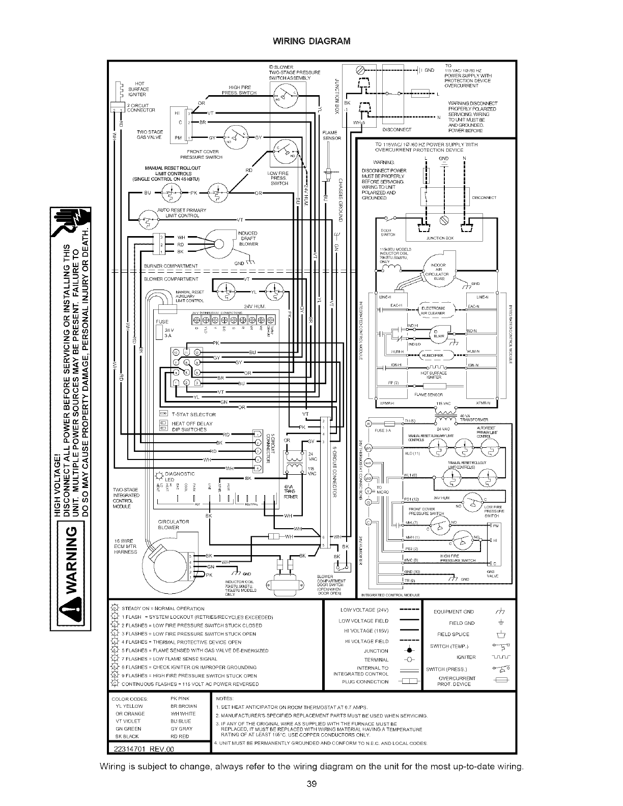
WiRiNG DIAGRAM
ID BLOV_R @TO
qll GND 1/5 VAC'I@/60 HZ
J
_o
t_.. I-
-J..I
n_W
Z_
W_
w_
n,'W
oo
wn,'
w_
_w
o-0
_Jo.
,-I w
0
Z
iZ
i
LOW VOLTAGE (24V) .....
LOW VOLTAGE FIELD
HI VOLTAGE (115V)
HI VOLTAGE FIELD .....
JUNCTION
TERMINAL
INTERNAL TO
INTEGRATED CONTROL
PLUG CONNECTION
EQUIPMENT GND
F_ELD GND
FIELD SPLICE
SWITCH (TEMP }
IGNITER
SWITCH (PRESS }
OVERCURRENT
PRO3" DEVICE
_7
=
©
COLOR CODES PK PINK
YL YELLOW BR BROWN
OR ORANGE WH WHITE
VT V_OLET BU BLUE
GN GREEN GY GRAY
BK BLACK RD RED
22314701 REV.00
NOTES:
1 SET HEAT ANTICIPATOR ON ROOM THERMOSTAT AT 07 AMPS
2 MANUFACTURER'S SPECIFIED REPLACEMENT PARTS MUST BE USED WHEN SERVIC_NG
3 IF ANY OF THE ORIGINAL W_RE AS SUPPLIED WITH THE FURNACE MUST BE
REPLACED, IT MUST BE REPLACED WITH W_RING MATER_AL HAVING A TEMPERATURE
RATING OF AT LEAST 105'C USE COPPER CONDUCTORS ONLY¸
4 UNiT MUST BE PERMANENTLY GROUNDED AND CONFORM TO N E C AND LOCAL CODES
Wiring is subject to change, always refer to the wiring diagram on the unit for the most up-to-date wiring.
39

5151 San Felipe, Suite 500
Houston, TX 77056
www.goodmanmf_, corn
© 2004-2008 Goodman Manufacturing Company, L.R
4O
