GOSAFE G-G797-777 GPS Tracker User Manual G79 G77 V1 1 2 x
Gosafe Company Limited GPS Tracker G79 G77 V1 1 2 x
GOSAFE >
User Manual
G79/G77 User Manual v1.1
Copyright © 2014 Gosafe

ATTENTION
Do not disassemble the device. Do not touch before unplugging the power supply if the device is
damaged, the power supply cables are not isolated or the isolation is damaged.
All wireless data transferring devices produce interference that may affect other devices which are
placed nearby.
The device may be connected only by qualified individuals.
The device must be firmly fastened in the predefined location.
The device is susceptible to water and humidity.
Changes or modifications not expressly approved by the party responsible for compliance could void
the user’s authority to operate the equipment. This equipment has been tested and found to comply
with the limits for a Class B digital device, pursuant to Part 15 of the FCC Rules. These limits are
designed to provide reasonable protection against harmful interference in a residential installation.
This equipment generates, uses and can radiate radio frequency energy and, if not installed and used
in accordance with the instructions, may cause harmful interference to radio communications.
However, there is no guarantee that interference will not occur in a particular installation. If this
equipment does cause harmful interference to radio or television reception, which can be determined
by turning the equipment off and on, the user is encouraged to try to correct the interference by one
or more of the following measures:
-- Reorient or relocate the receiving antenna.
-- Increase the separation between the equipment and receiver.
-- Connect the equipment into an outlet on a circuit different from that to which the receiver is
connected.
-- Consult the dealer or an experienced radio/TV technician for help.
INSTRUCTIONS OF SAFETY
This chapter contains information on how to operate “G79/G77” safely.
By following these requirements and recommendations you will avoid dangerous situations. You must
read these instructions carefully and follow the strictly before operating the device!
The device uses a 8V-32V DC power supply. The nominal voltage is 12V DC. It is advised to transport
the device in an impact-proof package.
Before usage, the device should be placed so that its LED indicators are visible, which show what status
of operation the device is in.
When connecting the connection cables to the vehicle, the appropriate jumpers of the power supply of
the vehicle should be disconnected.
Before dismounting the device from the vehicle, the connection must be disconnected.
LEGAL NOTICE
Copyright © 2014 Gosafe.
All rights reserved. Reproduction, transfer, distribution or storage of part or all of the contents in this
document in any form without the prior written permission of Gosafe is prohibited.
Other products and company names mentioned herein may be trademarks or trade names of their
respective owners.
Conents
1. Packing list ...................................................................................................... 4
2. Specifications .................................................................................................. 4
3. Features and event ......................................................................................... 5
4. Overview .......................................................................................................... 6
4.1. Front ...................................................................................................... 6
4.2. Rear ....................................................................................................... 6
5. Installation ....................................................................................................... 7
5.1. SIM card ................................................................................................ 7
5.2. Sensor calibration .................................................................................. 7
6. LED behavior ................................................................................................... 8
6.1. GSM LED: Green ................................................................................... 8
6.2. GPS LED: Yellow ................................................................................... 8
6.3. Power LED: Red .................................................................................... 8
7. User command ................................................................................................ 9
8. Message sample ........................................................................................... 13
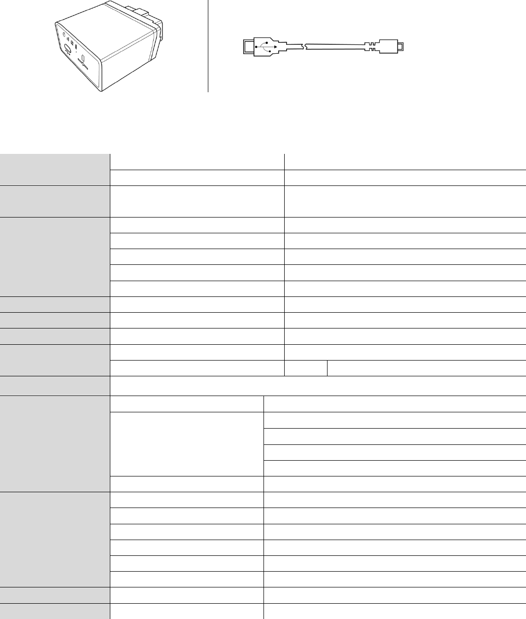
1. Packing list
2. Specifications
Physical Dimension 58.5(L)*50(W)*27(H)mm
Weight ~60g (With battery)
Environment Operating temperature -40℃ to +80℃ (without backup battery)
-10℃ to +50℃ (with backup battery)
Interface
*CAN CAN_H & CAN_L
*ISO ISO_K & ISO_L
*J1850 J1850+ & J1850-
VCC 1 PIN
GND 2 PIN
USB Mini USB 2.0
CPU ARM STM32F103
LED indicator 3 LED indicators GSM & GPS & POWER
Power supply External DC 8 to 32V
Backup battery Type Rechargeable, Li-Po 3.7V, 250mAh
Power consumption
Standby: 33mA@12V, Operating: 130mA@12V
GSM/GPRS
Antenna Built-In
Model
Cinterion BGS2-W
850/1900MHz
Class 12
TCP/IP over PPP
SIM card 1.8V & 3.3V
GPS
Internal antenna 25*25mm with amplifier
External antenna Not supported
Model u-Blox NEO 6M
Channel 50 Parallel Channels
Accuracy Autonomous<2.5M
Sensitivity -162dBm
Sensor Accelerate sensor Built-In, 3 axis
Flash storage 16Mbits Built-In
*Only for G79/G79W

3. Features and event
Features
OBDII interface
Built-in 3 axis acceleration sensor
A-GPS supported
GSM jamming detection
Private activity hour mode
Multiple user profiles switching automatically on preset conditions
Dynamic report interval on preset conditions
Fixed distance and fixed angle cornering report
Flexible report packet size on demand
Various single events report and combination event report supported
Hardware based Geo-fence supported up to 156
OTA firmware upgrade supported
Supported event list
Tracker is capable to report below specific events instantly via GPRS/SMS channel according to setting.
# Event name Status change event
1. Tow Quit tow Enter tow
2. Idle Quit idle Enter idle
3. Parking Quit parking Enter parking
4. Speed Enter preset speed range Leave preset speed range
5. GSM jamming Quit jamming Enter jamming
6. Geo fence Yes
7. GPS acquisition Yes
8. Health report Yes
9. Harsh brake Yes
10. Harsh acceleration Yes
11. Harsh left cornering Yes
12. Harsh right cornering Yes
13. Collision Yes
14. Turn over Yes
15. External power supply Under preset voltage threshold
16. Backup battery Under preset voltage threshold
17. *Wireless immobilizer status Connected Disconnected
18. *Tag status Tag absent Tag present
19. *Pair event Yes
20. *Tag low voltage No Yes
21. OBDII DTC event No Yes
22. Engine over revving No Yes
23. Engine over heat No Yes
24. Maintenance mileage notice No Yes
25. Engine oil changing notice No Yes
26. Tire changing notice No Yes
27. Engine status ON to OFF OFF to ON
28. SIM card balance notice Yes
Note: Above events by default are disabled please enable them by configuration tool if necessary or
contact your distributor for further information regarding this topic.
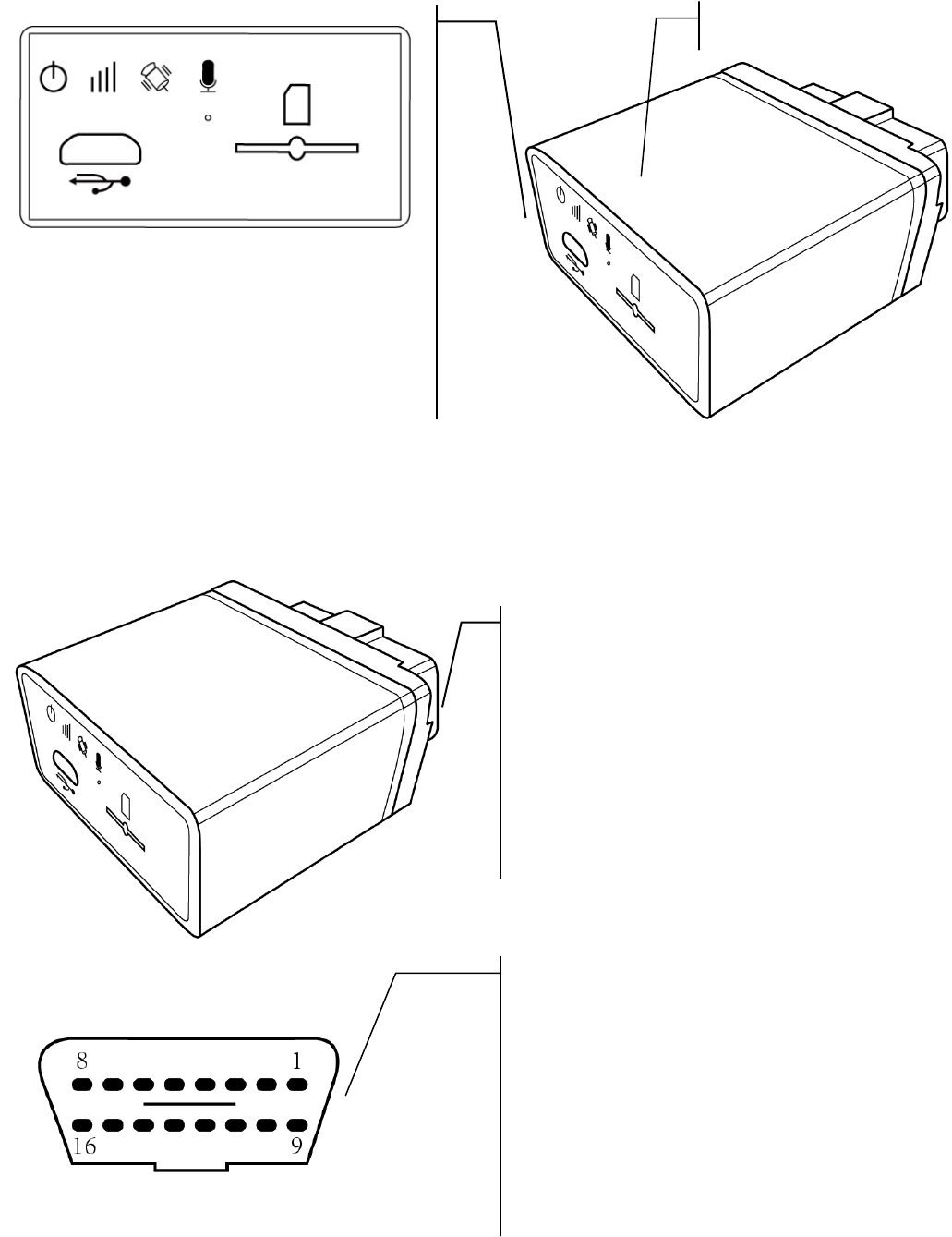
4. Overview
4.1. Front
4.2. Rear
Power LED indicator
GSM status LED indicator
GPS status LED indicator
Microphone
Mini USB 2.0 interface
SIM card holder
ODBII interface, protocol supported such as:
SAE J1850-PWM
SAE J1850-VPW
ISO 9141-2
ISO 14230-4
ISO 14230-4
ISO 15765-4
SAE J1939
And so on
PIN5: Signal Ground
PIN4: Chassis Ground
PIN6: CAN High (J-2284)
PIN7: ISO 9141-2 K Line
PIN14: CAN Low (J-2284)
PIN10: J1850 Bus-
PIN2: J1850 Bus+
PIN15: ISO 9141-2 L Line
PIN16: Battery power
GPS antenna side
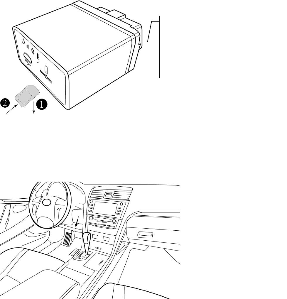
5. Installation
5.1. SIM card
5.2. Sensor calibration
This procedure is important for proper “harsh behavior” detection.
1. Locate OBDII interface around steering wheel, tracker will make a sound of “bi” when plug in.
2. Please do not start the car at the beginning and keep still as possible
3. Wait about 20 seconds.
4. Tracker will make sound of “bi” 3 times which indicating “static calibration” finished.
Note: For each external power cycle tracker will restart calibration procedure.
Step1:
Metal part of SIM card facing down.
Step2:
Insert and push SIM card to the button of SIM
holder to lock it firmly.
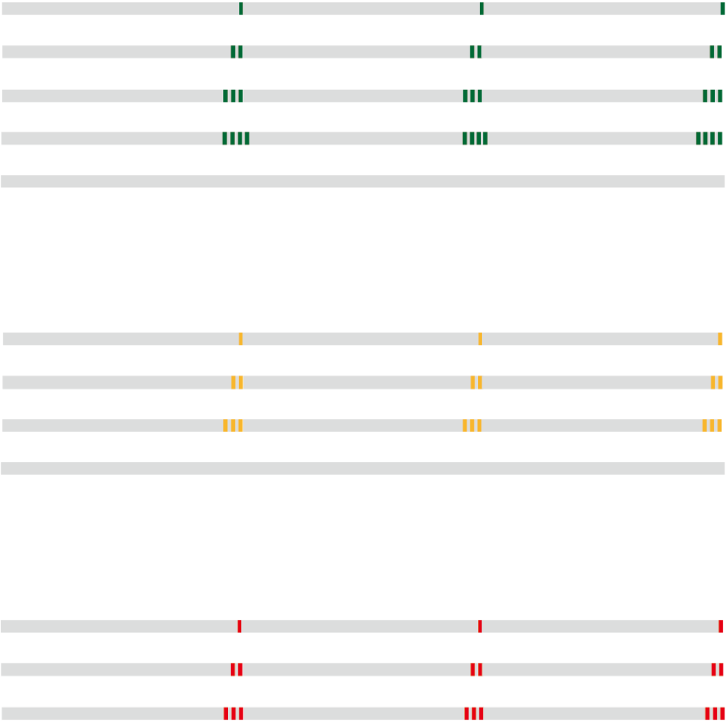
6. LED behavior
6.1. GSM LED: Green
Server socket connected: Flash once quickly every 3 seconds
GSM network registered: Flash twice quickly in a row every 3 seconds
GSM network unregistered: Flash 3 times quickly in a row every 3 seconds
SIM card error: Flash 4 times quickly in a row every 3 seconds
GSM module OFF: Never flash
6.2. GPS LED: Yellow
GPS fixed: Flash once quickly every 3 seconds
GPS unfixed: Flash twice quickly in a row every 3 seconds
GPS communication error: Flash 3 times quickly in a row every 3 seconds
GSM module OFF: Never flash
6.3. Power LED: Red
Using external power supply: Flash once quickly every 3 seconds
Using backup battery: Flash twice quickly in a row every 3 seconds
Backup battery low voltage: Flash 3 times quickly in a row every 3 seconds

7. User command
Command UNO0
This command is to set user phone number#1 that has authority to interact with tracker.
Example:
Phone number: 13800138000, country code: +86
1234,UNO0;+8613800138000 Tracker
User SMS G79 V1.00
UNO0:+8613800138000
EXT_PWR=11.94V
BAT=3.90V
#1
Command UNO1
This command is to set user phone number#2 that has authority to interact with tracker.
Example:
Phone number: 13800138000, country code: +86
1234,UNO1;+8613800138000 Tracker
User SMS G79 V1.00
UNO1:+8613800138000
EXT_PWR=11.94V
BAT=3.90V
#1
Command UPW0
This command is to change the default password 1234 for user phone number#1, 4 digits fixed.
1234,UPW0;5678 Tracker
User SMS G79 V1.00
UPW0:5678
EXT_PWR=11.94V
BAT=3.90V
#2
Command UPW1
This command is to change the default password 1234 for user phone number#2, 4 digits fixed.
1234,UPW1;5678 Tracker
User SMS G79 V1.00
UPW1:5678
EXT_PWR=11.94V
BAT=3.90V
#2
Command MEI
This command is to query GSM module IMEI of tracker, aka device ID.
1234,MEI Tracker

User SMS G79 V1.00
MEI:351535053999389
EXT_PWR=11.94V
BAT=3.90V
#3
Command BLS
This command is to set low balance notification/query current balance of tracker SIM card.
1234,BLS;*125 Tracker
User SMS G79 V1.00
BLS:*125
EXT_PWR=11.94V
BAT=3.90V
#4
Command PRQ
This command is to query current position of tracker.
1234,PRQ Tracker
User SMS G79 V1.00
LTM 2013-06-06 14:17:12
http://maps.google.com/maps?q=23.164374,113.428576&t=m&z=16
EXT_PWR=11.94V
BAT=3.90V
#5
Note: Position information in message may vary depending on setting/current status.
Command MGR
This command is to check current accumulation mileage of tracker, unit is meter.
1234,MGR Tracker
User SMS G79 V1.00
MGR:100000
EXT_PWR=11.94V
BAT=3.90V
#6
Command CID
This command is to check CCID of tracker SIM card.
1234,CID Tracker
User SMS G79 V1.00
CID:89860090191149028638
EXT_PWR=11.94V
BAT=3.90V
#7

*Command IMM
This command is to force immobilizing vehicle via wireless immobilizer.
1234,IMM;1;0;0 Tracker Remark
User SMS G79 V1.00
IMM:1;0;0
EXT_PWR=11.94V
BAT=3.90V
#8
IMM;0;0;0 is command to restore from
immobilizing.
Note: This command is for G79W only.
Command CAL
This command is to ask tracker to call specific phone number, tracker will call back after receiving
command.
1234,CAL;+8613800138000 Tracker
User SMS G79 V1.00
CAL:+8613800138000
EXT_PWR=11.94V
BAT=3.90V
#9
Command AGN
This command is to set volume gain of microphone.
1234,AGN;7;0 Tracker Remark
User SMS G79 V1.00
AGN:7;0
EXT_PWR=11.94V
BAT=3.90V
#9
AGN;<Parameter1>;<Parameter2>
<Parameter1>: Microphone gain
Range “0” to “7”, bigger value is louder volume.
<Parameter2>: Invalid
Command OBS
This command is to query current OBDII connectivity status.
1234,OBS Tracker Remark
User SMS G79 V1.00
OBS:1;0
EXT_PWR=11.94V
BAT=3.90V
#10
OBS:<Paramter1>;<Paramter2>
<Parameter1>:Connection status
“0” OBDII protocol is not connected.
“1” OBDII protocol is connected.
<Parameter2>:Specific protocol
“0” Automatic
“1” SAE J1850 PWM (41.6 kbaud)
“2” SAE J1850 VPW (10.4 kbaud)
“3” ISO 9141-2 (5 baud init, 10.4 kbaud)
“4” ISO 14230-4 KWP (5 baud init, 10.4 kbaud)
“5” ISO 14230-4 KWP (fast init, 10.4 kbaud)
“6” ISO 15765-4 CAN (11 bit ID, 500 kbaud)
“7” ISO 15765-4 CAN (29 bit ID, 500 kbaud)
“8” ISO 15765-4 CAN (11 bit ID, 250 kbaud)

“9” ISO 15765-4 CAN (29 bit ID, 250 kbaud)
Command VER
This command is to query current hardware and firmware version of tracker.
1234,VER Tracker Remark
User SMS G79 V1.00
VER:V1.02-US;V1.00
EXT_PWR=11.94V
BAT=3.90V
#10
VER:<Hardware version>;<Firmware version>
Command FWU
This command is to activate OTA firmware upgrade via GPRS.
1234,FWU Tracker
User SMS G79 V1.00
FWU
EXT_PWR=11.94V
BAT=3.90V
#10
The OTA upgrade process may cost around 10 minutes and there is a confirm message for it.
Tracker
User SMS G79 V1.10
Upgrade Success!
EXT_PWR=11.94V
BAT=3.90V
#11

8. Message sample
Content of message Explanation
G79 V1.00
LTM 2013-06-06 14:17:12
http://maps.google.com/maps?q=%n(,%e&t=m&z=16
GSM -52dBm
EXT_PWR=12.08V
BAT=3.86V
#30
Device name/Firmware version
Date/Time
Google map hyper link
GSM network signal strength
External power voltage
Built-in battery voltage
Consumed messages
Content of message Explanation
G79 V1.00
LTM 2013-06-06 09:41:22
GPS 1.55/0.50/3/4
N23.164302
E113.428456
SPD:0km/h 0
GSM -52dBm
EXT_PWR=12.13V
BAT=3.96V
#27
Device name/Firmware version
Date/Time
HDOP/ALTITUDE in meter/Fixed satellite number/Time of first fixed
N means north/S means south
E means east/W means west
Speed/Heading
GSM signal strength
External power voltage
Built-in battery voltage
Consumed messages
Content of message Explanation
G79 V1.00
LTM 2013-02-28 23:51:09
MCC/MNC/LAC/CID/RSSI
460/0/2503/962C/-53dBm
460/0/2731/40F4/-60dBm
460/0/2703/4050/-70dBm
GSM -58dB
EXT_PWR=5.13V
BAT=4.17V
#20
Device name/Firmware version
Date/Time
Base station information type
Main station, MNC/MNC/Local area code/Station ID/Signal strength
Neighbor station 1
Neighbor station 2
GSM network signal strength
External power voltage
Built-in battery voltage
Consumed messages
Content of message Explanation
G79 V1.00
LTM 2013-06-06 14:17:12
http://maps.google.com/maps?q=%n(,%e&t=m&z=16
ETD:6/ACC ON
GSM -52dBm
EXT_PWR=12.08V
BAT=3.86V
#301
Device name/Firmware version
Date/Time
Google map hyper link
Event ID/User defined event name/Data
GSM network signal strength
External power voltage
Built-in battery voltage
Consumed messages
This device complies with Part 15 of the FCC Rules. Operation is subject to the following two conditions: (1)
this device may not cause harmful interference, and (2) this device must accept any interference received,
including interference that may cause undesired operation.
This equipment complies with the FCC RF radiation exposure limits set forth for an uncontrolled
environment. This equipment should be installed and operated with a minimum distance of 20cm between
the radiator and any part of your body.