GRAUPNER 16005700 2.4 GHz Radio Control System User Manual GR 8 FCC x
GRAUPNER CO., LTD. 2.4 GHz Radio Control System GR 8 FCC x
GRAUPNER >
Contents
- 1. Manual
- 2. Addendum
Manual

GR-8 HoTT 2.4GHz Receiver Manual
Contents
Before use-------------------------------------------------------
• Support and Service-----------------------------------------------
- Customer Support------------------------------------------------------------
- Internet sales site-----------------------------------------------------
- A/S regulation-------------------------------------------------------
• OPENHOBBY A/S Center-----------------------------------------------------------
• Box Contents-----------------------------------------------------------------
• Warning Notes-----------------------------------------------------------
• System Features-----------------------------------------------------------------
• Specification-------------------------------------------------------------------
• Product Description--------------------------------------------------------------
• HoTT
• Operation
• Binding and Range test
• Switch Functions-------------------------------------------------------------------P7
• LED and Buzzer Indication------------------------------------------------------------------------
• Receiver Specification and Port Description
BEFORE USE
Thank you for purchasing Graupner GR-8 HoTT 2.4GHz Receiver. This system is extremely versatile
and may be used by beginners and pros alike. In order for you to make the best use of your system,
please read this manual carefully. If you have any difficulties while using your system, please consult
the manual, our online Frequently Asked Questions (on the web pages referenced below), your hobby
dealer, or the Graupner Service Center. Due to unforeseen changes in production procedures, the
information contained in this manual is subject to change without notice.
SUPPORT AND SERVICE
• Customer support
Please feel free to ask any question by e-mail or phone. We’ve been trying to deal with your question.
We are open from nine to six, Monday to Friday in Korea. We may respond to your question by e-mail
as soon as possible when we are close.
• Internet sales site
Please feel free to contact “www.openhobbby.com” to get all information on product features,
specifications, running events and the newest product line up.
• A/S regulation
Only when the product is faulty after normal operation within the warranty period, we will repair the
product for free based on our regulations. The repair will be paid for by the consumer when the
damage is due to use in improper ways or beyond the warranty period.

• Warranty regulation
Refer the WARRANTY CARD in a Package
OPENHOBBY A/S CENTER
202 Dong- 201, Chunui Techno-Park II, 18, 198 street, Bucheon-ro, Wonmi-Gu, Bucheon-Shi,
Gyungki-Do KOREA 420-857
Phone: 82-70-7863-3674 Fax: 82-70-7863-3670
Customer Service E-mail: service@openhobby.com
BOX CONTENTS
GR-8 HoTT Receiver
Manual
Warranty Card
Temperature/Voltage Sensor (S8362)
WARNING NOTES
• Never operate your car or truck in a crowded street with traffic. Especially, do not drive in a place
near railway, chemical substance, gas to prevent any damage.
• This product is not intended for use by inexperienced or disabled person without direct supervision
of a responsible, knowledgeable adult. This is not suitable for children under 18 years.
• The radio system is affected by signal environment and the electronic jamming signals can cause
disorientation and loss of control of your aircraft.
• Please read the manual to make the best use of the product
• Make sure to check all operations of channels before use.
• For the safe use, please operate the Range Check Mode before use.
• Be careful not to turn your transmitter off while in use.
• Do not touch or grab antenna during the use.
• Do not operate your model in the rain or run through standing water
• Fail Safe should be set before use to prevent uncontrollable situation occurred by any interruption.
It is recommended to set throttle channel to Neutral condition or brake condition.
• Always operate your program setup mode after stopping motor’s power or engine and disconnecting
drive battery.
• Make sure whenever you start operating your transmitter, turn your transmitter on and then turn your
receiver on. Whenever you stop your transmitter, turn your receiver off first and your transmitter.
• Always disconnect the battery pack from the speed control when not in use to avoid short circuits
and possible fire hazard.
• Always insulate exposed wiring with heat shrink tubing or electrical tape to prevent short circuits,
which can damage ESC.
• Don‘t make any changes on the structure and design of your controller unless they are described in
the manual.
• Only those components and accessory parts which have been recommended by us may be used.

Use only genuine and matching Graupner/SJ connectors and accessory parts.
• Make sure whenever you start connecting and operating the controller, that your transmitter is
switched on, and has the throttle set to position “STOP”.
Binding & RF Range Test
BIND
Press and hold Bind button for 3 sec while your receiver is powered on and then LED indicator is off.
Now press Bind button of your transmitter and then receiver’s LED indicator is off.
RF RANGE TEST
When BIND button is touched after the connection between transmitter and receiver, RF RANGE
TEST is now activated. RF TEST is continued during 90 seconds and it is automatically deactivated.
RF RANGE TEST is deactivated by touching BIND button during RF RANGE TEST mode.
Please note that your model is not controllable if your model is far away from you during Test mode
due to the short transmit distance.
Receiver Specification and Port Description
1. GR-8 Receiver Specification
2. Receiver Port Description
Extra Function
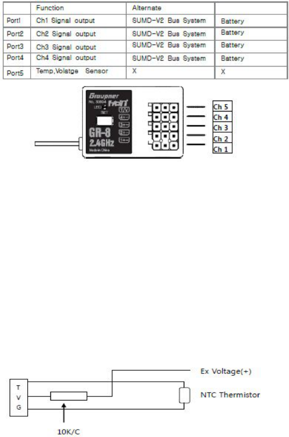
1) Port 1, 2, 3, 4 should be connected to servo or ESC.
2) Port 5 supports low voltage warning alarm with beep and LED indicator.
In addition, it is available to use with telemetry sensor.
When using receiver battery (Nixx 4~5 cell, LiPo 2 cell), it needs to be connected to Port3.
As for low voltage warning alarm, the default value is 3.7V.
Caution: When using LiPo 2 cell for receiver battery, you may protect your battery from any damage
by using optional smart box, which ensures voltage adjustment and warning alarm function.
3) Port 5 is designed that it will activate the beep and LED indicator when your engine gets hot.
Caution: Regardless of receiver battery type, warning alarm is activated if battery capacity is lower
than 70%. Therefore, you need to use your model after fully charging battery.
<Voltage/Temperature Sensor Configuration>
Ex Voltage (+): Connect with ESC Power Connector(+)
NTC Thermistor: Connect with Engine Head
Connect sensor to Port 4 as above. Temp sensor should be installed on engine head and Volt sensor
should be installed on ESC power connector (+).
Caution: Warning alarm may not be activated, depending on weather condition or mounting location.
If it is not activated, change mounting location or adjust temperature value with optional smart box
(Telemetry box). (Default value: 100℃)
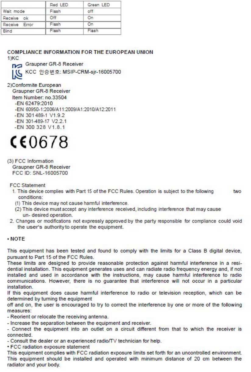
4) Receiver Indicator LED’s
LED OFF: Very good signal condition
LED blinks: Not good signal condition
LED ON: No signal
LED and Buzzer indication
• ENVIRONMENTAL PROTECTION NOTES
This product must not be disposed of with other waste. Instead, it is the user’s responsibility to their
waste equipment by handing it over to a designated collection point for the recycling of waste
electrical and electronic equipment. The separate collection and recycling of your waste equipment at
the time of disposal will help to conserve natural resources and ensure that it is recycled in a manner
that protects human health and the environment. For more information about where you can drop off
your waste equipment for recycling, please contact your local city office, your household waste
disposal service or where you purchased the produce.