GRAUPNER 16005800 Gyro Receiver Graupner/SJ HoTT User Manual 33583 de en fr indd
GRAUPNER CO., LTD. Gyro Receiver Graupner/SJ HoTT 33583 de en fr indd
GRAUPNER >
User Manual
GRAUPNER/SJ GmbH – Postfach 1242 – 73230 Kirchheim/Teck – www.graupner.de
Bedienungsanleitung
Operating Instructions
Notice d’utilisation
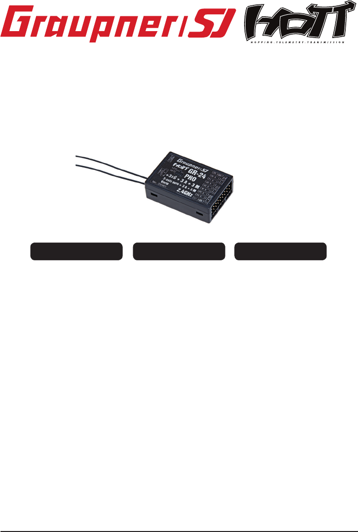
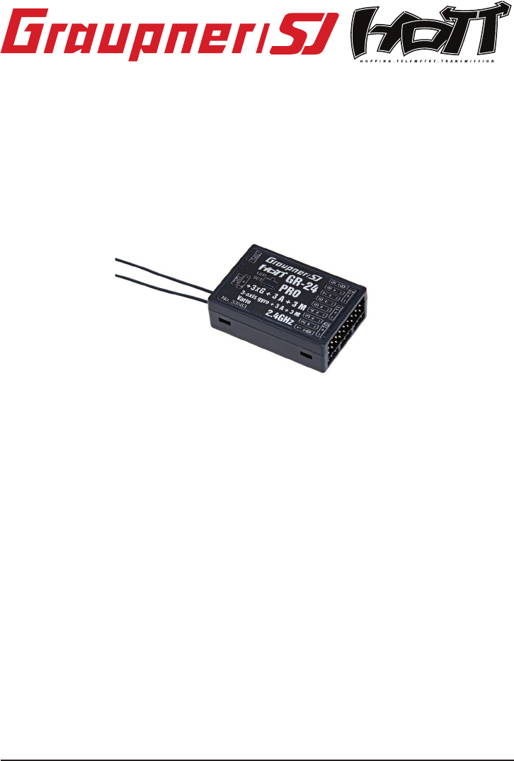
33583 Empfänger GR-24 PRO 3xG+3A+3M+Vario
INHALTSVERZEICHNIS:
1. Hinweise .....................................................................................................................02
2. Funktionen .................................................................................................................04
2.1. Binding .........................................................................................................................04
2.1.1Binding mehrerer Empfänger ......................................................................................04
2.2. Fail-Safe Funktion ........................................................................................................ 04
2.3 Reichweitentest............................................................................................05
2.4 Einbau ins Modell (Fläche).............................................................................................05
2.5 Einbau ins Modell (Heli).................................................................................................05
3. Empfänger .................................................................................................................. 06
3.1. Anschluss ....................................................................................................................06
3.2. Empfänger Einstellmenü .............................................................................................. 07
3.3. Freie Mischer ............................................................................................................... 08
3.4 Zuordnen der Kreiselachsen.............................................................................................10
4. Programmierung der Gyro Einstellungen ...............................................................12
4.1. Programmierung der PID Regelung ............................................................................12
4.2. Faktor programmieren ................................................................................................. 13
4.2.1Programmieren bei Sendern mit Proportionalgebern ...................................................13
4.2.2Programmieren ohne Proportionalgeber........................................................................14
4.3 Initialisierung des Kreisels.............................................................................................14
5. Firmwareupdate ......................................................................................................... 16
6. Konformitätserklärung / Garantie /Herstellererklärung / Entsorgungshinweise ........... 50
Manual V1.0
Revision: Januar 2013
FRANÇAIS page 34ENGLISH page 18DEUTSCH Seite 2
Manual Receiver GR-24PRO 3xG+3A+3M+Vario Graupner HoTT 2. 4
Operating Instructions
1. Notes......................................................................................................................19
2. Functions...............................................................................................................21
2.1. Binding.........................................................................................................21
2.1.1 Binding multiple receivers...................................................................................21
2.2. Fail-Safe function...............................................................................................21
2.3 Range-checking...........................................................................................22
2.4. Installation in the model (airplane).....................................................................22
2.5. Installation in the model (heli)..........................................................................22
3. Receiver..................................................................................................................23
3.1. Connections..................................................................................................24
3.2. Receiver set-up menu........................................................................................25
3.3. Free mixers.......................................................................................................25
3.4 Assigning the gyro axes......................................................................................27
4. Programming the gyro settings............................................................................29
4.1. Programming PID correction..............................................................................29
4.2. Programming the factors....................................................................................30
4.2.1 Programming, transmitter with proportional controls............................................30
4.2.2 Programming, transmitter without proportional controls.......................................31
4.3 Initialising the gyro............................................................................................31
5. Firmware update.............................................................................................33
6. Conformity declaration / Guarantee / Manufacturer’s declaration / Disposal..50
18
33583 Receiver GR-24PRO 3xG+3A+3M+Vario
MANY THANKS
for deciding to purchase the Graupner/SJ HoTT 2.4 system. Please read right through these operating
instructions before you attempt to install and operate the Graupner HoTT 2.4 system.
• The receiver stabilises the model aircraft in difcult, windy conditions, acting on a maximum of
three axes
• Proportional gyro suppression for natural ying characteristics
• Excellent stabilisation for smooth, accurate manoeuvres
• The triple-axis gyro endows even very demanding aerobatic models with docile ying
characteristics, and greatly simplies aerobatics
• Aerobatic manoeuvres can be own much more accurately
• Simple gyro assignment procedure
• Facility to adjust parameters using HoTT telemetry
• Altitude sensor for vario and altimeter function
1. APPROVED USAGE
The receiver is intended exclusively for use in radio-controlled models. Any other usage is prohibited,
and may result in damage to the receiver or model, and serious personal injury. We grant no guarantee
and accept no liability for any type of use outside the stipulated range.
Not suitable for children under fourteen years. This receiver is not a toy!
The receiver is also equipped with a telemetry function which is only available in combination with a
Graupner/SJ HoTT 2.4 system. If you do not own a Graupner/SJ HoTT 2.4 system, the receiver will not
work.
Please start by reading through the whole instructions before you attempt to install and operate the
receiver.
These operating instructions are an integral part of the product. They contain important notes on
operating and handling the receiver. For this reason please store the operating instructions in a safe
place, and pass them on to the new owner if you ever dispose of the product. Failure to observe the
operating instructions and safety notes invalidates the guarantee.
Here at Graupner we are constantly working on the further development of all our products; for this
reason we are obliged to reserve the right to introduce changes to the set contents in form, technology
and features.
Please understand that we will not countenance claims resulting from information and illustrations in
these operating instructions.
Please store the operating instructions in a safe place for future reference!
1.1 SAFETY NOTES
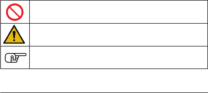
KEY TO THE SYMBOLS
Caution!
This symbol alerts you to prohibited actions which must be observed at all
times. Any failure to observe the prohibited action indicated in this way may
prevent the equipment working, and endanger the safety of the operator.
Caution!
This symbol alerts you to information which must be observed at all times.
Any failure to observe the information indicated in this way may prevent the
equipment working properly, and endanger the safety of the operator.
This symbol indicates information which should always be observed in order to
ensure that the equipment operates reliably.
Manual Receiver GR-24PRO 3xG+3A+3M+Vario Graupner HoTT 2. 4 19
20 Manual Receiver GR-24PRO 3xG+3A+3M+Vario Graupner HoTT 2. 4
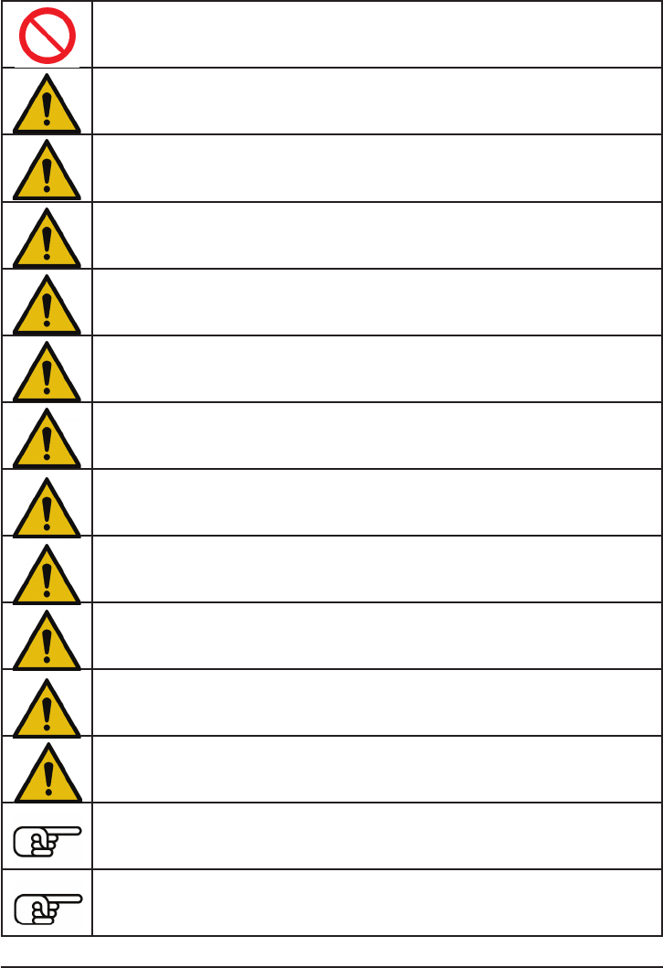
SAFETY NOTES
Warning!
The receiver must never be operated under the inuence of medication, alcohol, drugs etc.
Caution!
Any deviation from the instructions may have an adverse effect on the function and
operational security of the receiver, and must be avoided under all circumstances.
Caution!
The operator bears full responsibility for using the receiver. The only way to guard against
personal injury and property damage is to handle the equipment carefully and use it
exactly as recommended.
Caution!
Not suitable for children under fourteen years.
Caution!
Protect the receiver from dust, soiling, damp and foreign bodies. Never subject the receiver
to excessive vibration, heat or cold.
Caution!
During the programming process you must bear in mind that an internal combustion
engine or electric motor could unexpectedly burst into life at any time.
Caution!
Avoid subjecting the receiver to shocks and pressure. Check the receiver regularly for
damage to the case and cables. Do not re-use a receiver which is damaged or has become
wet, even after it has dried out again.
Caution!
When deploying the cables ensure that they are not under tension, not tightly bent (kinked)
or fractured. Avoid sharp edges which could damage cable insulation.
Caution!
Ensure that all plug-in connections are rmly seated. Do not pull on the wires when
disconnecting plugs and sockets.
Caution!
The receiver must not make physical contact with the model’s fuselage, hull or chassis, as
this would allow motor vibration and landing shocks to be transferred directly to it.
Caution!
It is not permissible to carry out modications of any kind to the receiver. Any changes
invalidate product approval, and you forfeit any insurance protection.
Caution!
Ensure that the equipment is working correctly and at full range before every ight. Check
the state of the batteries at regular intervals.
Note!
Ensure that all your HoTT components are loaded with the current version of the software
at all times.
Note!
Safety is no accident, and radio-controlled models are not playthings!

1.2 GENERAL NOTES
• The receiver’s integral gyros are very fast, high-resolution components. This means that you
should always use high-speed digital servos wherever possible, so that the gyro’s corrective
signals are converted directly and accurately into servo movement; this helps to prevent the
model oscillating.
• Keep all servo extension leads as short as possible.
• When switching on or adjusting the radio control system, it is essential to keep the transmitter
aerial at least 15 cm from the receiver aerial(s). If the transmitter aerial is too close to the receiver
aerials, the receiver will be swamped and the red LED on the receiver will light up. The transmitter
responds with a ashing red LED and repeated beeps at approximately one-second intervals, i.e.
the radio control system reverts to fail-safe mode. If this should happen, increase the distance
until the audible warning ceases, and the blue transmitter LED lights up constantly once more.
The red LED on the receiver should now be off.
2. FUNCTIONS
2.1. Binding
The Graupner/SJ HoTT 2.4 receiver must be “bound” to “its” Graupner/SJ HoTT 2.4 RF module
(transmitter) before a radio link can be created between them; this process is known as “binding”.
Binding is only necessary once for each combination of receiver / RF module, so the binding procedure
described below only needs to be repeated if you add more receivers. However, binding can be repeated
at any time if you wish; for example, if you switch transmitters. This is the procedure in detail:
• Binding is only possible if the receiver has not been linked with a bound transmitter since being
switched on (red LED lights); press the SET button to set the receiver to BIND mode.
• If you have already bound a receiver to the transmitter, and wish to bind the receiver to a new
model memory, this is the procedure:
• Switch the transmitter’s RF section off in the “Basic model settings” menu.
• Switch the receiver on, and press the SET button to set it to Bind mode.
• Initiate binding in the transmitter’s “Basic model settings” menu.
• If the receiver’s red LED moved within about 10 seconds to green, the Binding Operation was
completed successfully.
• Your transmitter / receiver combination is now ready for use.
• However, if the red LED continues to glow, then the binding process has failed. If this should
happen, repeat the whole procedure.
2.1.1. Binding multiple receivers per model
If necessary it is also possible to bind more than one receiver to a particular model. First bind each
receiver individually as described earlier.
When the system is actually in use, the receiver which was last bound acts as the Master unit, and any
telemetry sensors installed in the model must be connected to this receiver, as only the Master receiver
transmits the data to the ground using the downlink channel. The second - and any other - receivers
operate in Slave mode, in parallel with the Master receiver, with the downlink channel switched off.
The channel mapping function of HoTT telemetry also allows the control functions to be divided up
amongst multiple receivers, or alternatively the same control function to be assigned to multiple receiver
outputs. For example, this is useful if you wish to actuate each aileron with two servos instead of just
one.
2.2. Fail-Safe function
In the receiver’s default state, all connected servos remain in their last valid position (“Hold” mode)
if a fail-safe situation should arise. In fail-safe mode the red LED on the receiver lights up, and the
transmitter generates an audible alert by beeping at a rate of around one per second.
You can exploit the safety potential of this option by at least setting the throttle position (for internal-
combustion powered models) to Idle, or the motor function (electric-powered models) to “Stop”, or “Hold”
for a model helicopter, if a fail-safe event should occur. These settings ensure that the model is less
likely to y out of control if interference should occur, thereby helping to avoid property damage or even
personal injury.
Read the operating instructions supplied with your radio control system for more details.
The gyro system remains active in a fail-safe situation.
Manual Receiver GR-24PRO 3xG+3A+3M+Vario Graupner HoTT 2. 4 21
2.3 Range-checking
The range of your Graupner/SJ HoTT 2.4 system can be checked as described in the following
instructions. We recommend that you ask a friend to help you with the procedure.
Ideally the receiver should already be bound to the transmitter. Install it in the model in its nal position.
• Switch the radio control system on, and wait until the red LED on the receiver goes out. The servo
movements can now be observed.
• Place the model on a at surface (pavement, close-mown grass, earth), and ensure that the
receiver aerials are at least 15 cm above the ground. It may be necessary to pack up the model
to achieve this for the period of the range-check.
• Hold the transmitter away from your body at hip-level. Don’t point the transmitter aerial straight at
the model; instead rotate or angle the aerial tip in such a way that it is vertical when you operate
the transmitter controls.
• Select range-check mode, as described in the transmitter instructions.
• Walk away from the model, moving the transmitter sticks. If you detect an interruption in the radio
link at any time within a distance of about 50 m, see if you can reproduce the problem.
• If your model is tted with a motor or engine, switch it on or start it, so that you can check effective
range when potential interference is present.
• Walk further away from the model to the point where full control is no longer possible.
• At this point you should manually switch off range-check mode.
The model should now respond to the controls again. If this is not 100% the case, do not use the system.
Contact the Graupner/SJ Service Centre in your locality and ask their advice.
We recommend that you carry out a range-check before every ight, simulating all the servo movements
which occur in ight. To guarantee reliable model operation, radio range must always be at least 50 m
on the ground.
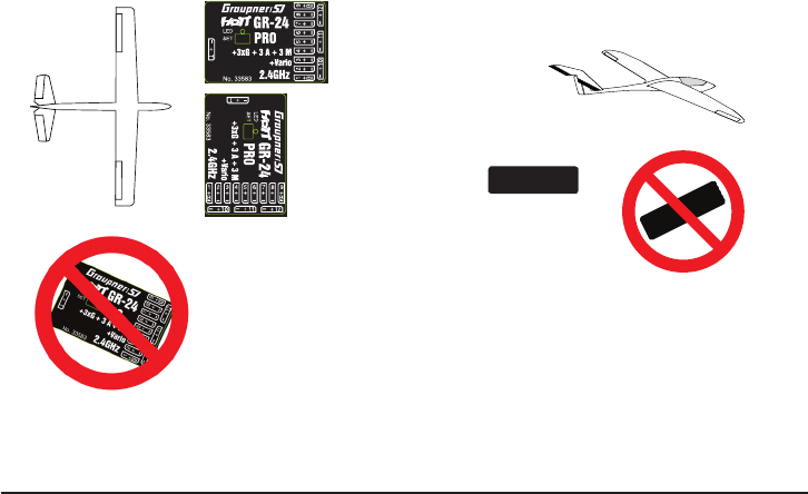
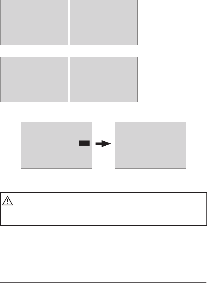
2.4 INSTALLATION IN THE MODEL (AIRPLANE)
The gyro receiver must be installed straight and at right angles to aircraft longitudinal axis,
so that the rotors can work as intended, because of the accelerometer in addition also
horizontal to the longitudinal axis.
22 Manual Receiver GR-24PRO 3xG+3A+3M+Vario Graupner HoTT 2. 4
OK
OK
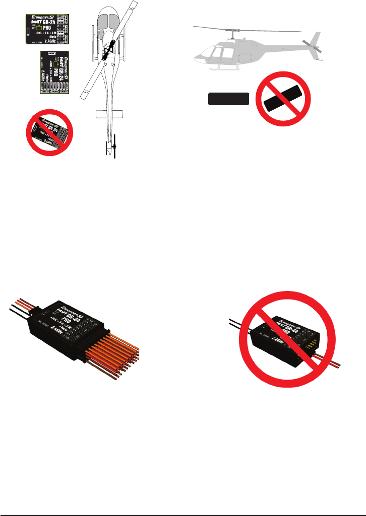
2.5 INSTALLATION IN THE MODEL (HELI)
The receiver has to be aligned strictly at right angles and parallel to the oor on the receiver platform
on the helicopter.
3. RECEIVER
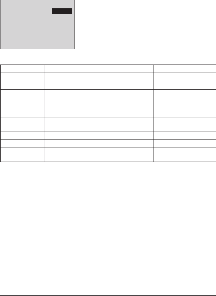
3.1 Connections
Connect the servos to the row of sockets on one end of the receiver. The connectors are polarised: note
the small chamfers on one side. Never use force - the connectors should engage easily. The polarity is
also printed on the receiver; the negative wire (-) is brown, the positive (+) red and the signal orange.
The servo sockets of Graupner/SJ HoTT 2.4 receivers are numbered sequentially.
The socket for channel 8 can also be programmed to deliver a (digital) sum signal (see section 3.2:
Receiver set-up).
Power supply
The receiver does not feature specic sockets for connecting the battery. We recommend that you
connect the power supply to the socket(s) close to the servos already connected to the receiver. If you
wish to connect multiple separate batteries, the batteries must be of the same nominal voltage and
capacity. Never connect batteries of different type, or packs of greatly differing states of charge, as this
can cause effects similar to a short-circuit. If you encounter this problem, we recommend the use of a
voltage stabiliser unit (e.g. PRX-5A receiver power supply, Order No. 4136) between the batteries and
the receiver.
Telemetry
The optional telemetry sensors are connected to the socket marked “T” (Telemetry). In addition, the
update is performed on this socket (see point 5).
Manual Receiver GR-24PRO 3xG+3A+3M+Vario Graupner HoTT 2. 4 23
OK
OK
OK
PROGRAMMING THE GENERAL RECEIVER SETTINGS:
The receiver can be programmed using a suitable HoTT transmitter or the SMART-BOX (Order No.
33700).
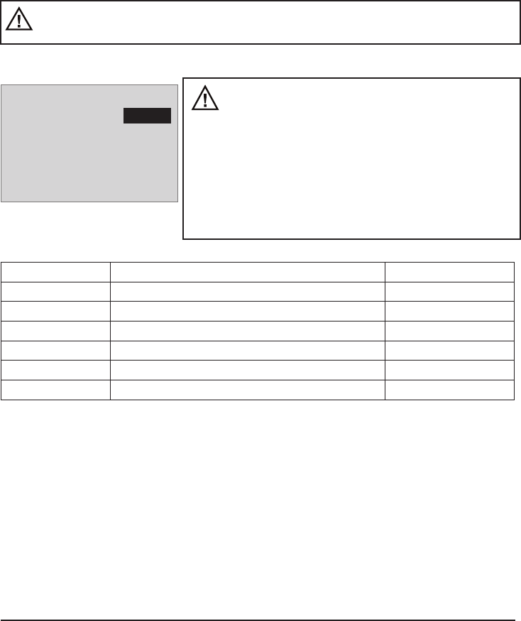
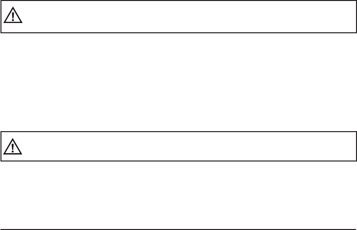
3.2 RECEIVER SET-UP MENU
The receiver set-up menu appears in the “Telemetry” menu
under SETTINGS / DISPLAYS; alternatively - if you are using a
SMART-BOX - under SETTING & DATAVIEW. The method of
accessing this menu is described in the operating instructions
supplied with your transmitter or the Smart-Box.
Display Explanation Settings
RECEIVER 1.0 1.0 indicates the version of the receiver’s rmware -
Type of Model Selection of modeltype Plane, Heli
ALARM VOLT. Alarm threshold for the receiver’s low voltage
warning
2.5 - 24.0 V
Default setting: 3.8 V
ALARM TEMP. Receiver overheating warning 50 - 80° C
Default setting: +70° C
Max. altitude maximum altitude 0 - 2500 m
in 25 m increments
PERIOD Cycle time (frame rate) in ms 10 / 20 ms
SUMD at CH8 Digital sum signal at channel 8 Yes / No
LANGUAGE Select menu language German, English, French,
Italian or Spanish
Model type selection (Type of model): here you can choose the model type.
By selecting “Plane” you will be able to access the gyrosettings for surface models, as described in
chapter 4.
The selection “Heli” will be made available through a future software update. It will enable a receiver-
integrated ybarless system, which can be adjusted inside the transmitters telemetry settings.
Low-voltage warning (ALARM VOLT): if the receiver voltage falls below the set value, a low-voltage
warning is generated by the transmitter’s RF module in the form of the “general alarm tone”: a regular
beeping at a rate of about one per second; alternatively the speech output message “Receiver voltage”.
Temperature warning (ALARM TEMP): if the receiver temperature exceeds the set temperature
threshold, a warning is generated by the transmitter’s RF module in the form of the “general alarm tone”:
a regular beeping at a rate of about one per second; alternatively the speech output message “Receiver
temperature”.
Maximum altitude (Max. altitude): at this point you can enter a maximum altitude, at which an alarm
is triggered, either via the transmitter’s RF module in the form of the “general alarm tone”: a regular
beeping at a rate of about one per second; alternatively the speech output message “Height”. Note:
the model’s actual height is adopted as zero when the receiver is switched on; the indicated height is
therefore the altitude relative to the launch point.
RECEIVER 1.0 < >
>Type of Model:
ALARM VOLT:
ALARM TEMP:
max altitude:
>Period:
>SUMD at K8:
LANGUAGE:
Plane
3.8V
70°C
125m
10ms
No
english
24 Manual Receiver GR-24PRO 3xG+3A+3M+Vario Graupner HoTT 2. 4
Manual Receiver GR-24PRO 3xG+3A+3M+Vario Graupner HoTT 2. 4 25
Cycle time (PERIOD): if your system is used exclusively with digital servos, you can set a cycle time
(frame rate) of 10 ms at this point. If your system includes some or all analogue servos, you should
always select 20 ms, as many analogue servos cannot process the higher frame rate, and may respond
by “jittering” or “growling”.
HoTT sum signal (SUMD): if you activate the digital sum signal at channel 8, a sum signal containing
eight channels is present at this socket, instead of a servo signal. The HoTT receiver congured as
SUMD constantly generates a digital sum signal from 8 control signals from the transmitter and makes
this signal available at the appropriate servo socket, which is receiver-specic. At the time these
instructions were revised, this type of signal is used by several of the latest electronic developments in
the area of ybarless systems, heavy-duty airborne power supplies, etc.
WARNING: if you wish to use this facility, it is essential to observe the set-up information
supplied with the devices connected to the receiver, otherwise there is a risk that your model
may be uncontrollable!
3.3 FREE MIXERS
Important note: If you wish to use the gyros, you
must always set the tail type to ‘normal’ in the trans-
mitter’s model type menu. If your model is a delta, fea-
tures a V-tail, or has two elevator servos, you must use the
receiver mixer - not the transmitter mixer - to control these
control surfaces, since the gyro stabilisation system will
have no effect on these servos otherwise. The four receiver
mixers work ‘downstream’ of the gyros. If you have already
programmed mixer functions in the “Wing mixers” or “Free
mixers” menu of your HoTT transmitter, you must ensure that
those mixers do not overlap with those available in this menu!
Screen Display Key Settings
MIXER Mixer select 1, 2....4
FROM CHANNEL Signal source / source channel 0,1,2,...6
TO CHANNEL Target channel 0,1,2,...6
TRIM Trim position in % -15 - + 15%
TRAVEL- Travel limit at % Servo travel -150 bis +150%
TRAVEL+ Travel limit at % Servo travel -150 bis +150%
MIXER: up to four mixers can be programmed simultaneously. You can switch between Mixer 1, Mixer
2, … and mixer 4 in the “Mixer” line.
The following settings only affect the mixer selected in this line.
FROM CHANNEL: the signal present at the signal source (or source channel) is mixed in to the target
channel (TO CHANNEL) to an extent which can be set by the user. The method of setting up the values
is analogous to the “Free mixers” menu in HoTT transmitters.
TO CHANNEL: part of the source channel signal (FROM CHANNEL) is mixed into the target channel
(TO CHANNEL). The mixer ratio is determined by the percentage values entered in the “TRAVEL-“ and
“TRAVEL+” lines. Select “0” if you do not require the mixer.
Mixer ratio (TRAVEL-/+): in these two lines you can dene the mixer ratio in relation to the source
channel (FROM CHANNEL); the value is set separately for both directions.
RX FREE MIXER < >
>MIXER:
MASTER CH:
SLAVE CH:
>TRIM:
>TRAVEL-:
TRAVEL+:
1
1
6
+0%
+100%
+100%

Programming examples:
V-tail with rudder differential
RX FREE MIXER < >
>MIXER:
MASTER CH:
SLAVE CH:
>TRIM:
>TRAVEL-:
TRAVEL+:
1
3
4
+0%
+100%
+100%
RX FREE MIXER < >
>MISCHER:
MASTER CH:
SLAVE CH:
>TRIM:
>TRAVEL-:
TRAVEL+:
2
4
3
+0%
-60%
+100%
RX FREE MIXER < >
>MIXER:
MASTER CH:
SLAVE CH:
>TRIM:
>TRAVEL-:
TRAVEL+:
3
4
4
+0%
+100%
+60%
Differential is not normally necessary with this tail type. Mixer 3 is not required if you do not need rudder
differential, and TRAVEL- for mixer 2 must then be set to -100%.
Alternatively you may prefer to carry out the programming using the transmitter menu. A ‘Rudder
elevator’ mixer can be set up at the transmitter instead of ‘Free mixer 3’ at the receiver; the mixer should
be set up asymmetrically, e.g. +30%, -30%. This option frees up one mixer at the receiver.
Delta with aileron differential (1 aileron)
RX FREE MIXER < >
>MISCHER:
MASTER CH:
SLAVE CH:
>TRIM:
>TRAVEL-:
TRAVEL+:
1
2
3
+0%
+100%
+60%
RX FREE MIXER < >
>MISCHER:
MASTER CH:
SLAVE CH:
>TRIM:
>TRAVEL-:
TRAVEL+:
2
3
2
+0%
-100%
-100%
RX FREE MIXER < >
>MISCHER:
MASTER CH:
SLAVE CH:
>TRIM:
>TRAVEL-:
TRAVEL+:
3
2
2
+0%
+60%
+100%
In this example aileron differential is set to 40%. Alternatively you may prefer to carry out the programming
using the transmitter menu. An ‘Aileron elevator’ mixer can be set up at the transmitter instead of
‘Free mixer 3’ at the receiver; the mixer should be set up asymmetrically, e.g. +30%, -30%. This option
frees up one mixer at the receiver.
Two elevator servos
(channel 6 for the second elevator servo)
RX FREE MIXER < >
>MISCHER:
MASTER CH:
SLAVE CH:
>TRIM:
>TRAVEL-:
TRAVEL+:
1
3
8
+0%
+100%
+100%
26 Manual Receiver GR-24PRO 3xG+3A+3M+Vario Graupner HoTT 2. 4
Manual Receiver GR-24PRO 3xG+3A+3M+Vario Graupner HoTT 2. 4 27
Only for transmitters without a buttery (crow) mixer (e.g. mx-10 HoTT):
If a buttery (crow) mixer is required, you will not be able to use one of the two functions ‘differential’ or
‘landing ap’ adjustment, as two mixers are needed for this.
Programming example:
RX FREE MIXER < >
>MIXER:
MASTER CH:
SLAVE CH:
>TRIM:
>TRAVEL-:
TRAVEL+:
1
1
2
+0%
+100%
+100%
RX FREE MIXER < >
>MISCHER:
MASTER CH:
SLAVE CH:
>TRIM:
>TRAVEL-:
TRAVEL+:
2
1
5
+0%
-100%
-100%
Programming example:
RX FREE MIXER < >
>MISCHER:
MASTER CH:
SLAVE CH:
>TRIM:
>TRAVEL-:
TRAVEL+:
1
1
2
+0%
+100%
+100%
RX FREE MIXER < >
>MISCHER:
MASTER CH:
SLAVE CH:
>TRIM:
>TRAVEL-:
TRAVEL+:
2
1
3
+0%
-100%
-100%
3.4 ASSIGNING THE GYRO AXES
Aileron servos: you should enter the value 2 in this line if your model has two aileron servos; in this
case the gyro for channel (servo) 2 also acts on servo 5. If the ailerons are also used as aperons or
speedbrakes, gyro suppression is based on the sum of both channels.
CAUTION: the servo reverse setting must be the same for both aileron servos, i.e. either both
‘normal’ or both ‘reverse’. If this is not possible, on no account should you reverse one servo in
the transmitter menu. The only option is to re-install it in the model by turning it round physically.
However, if your model is tted with programmable servos (e.g. Graupner DES, HVS or HBS types
- see the instructions for the update program ‘Firmware_Upgrade_grStudio - then it is possible to
reverse the direction of rotation at the servo itself.
Please read the installation notes on page 22-23 of these instructions. The rst step is to dene the three
gyro axes and the orientation of the receiver. This is accomplished by switching on the transmitter and
model, and selecting ‘New setting: yes’ in the receiver’s ‘Gyro settings’ menu.
• Now move the stick for any control surface to full travel in one direction; in the following example
we use the aileron channel.
• The detected axis (aileron) is highlighted (black background). (In the receiver’s default state the
value for all axes is shown as ‘+0’; the axes can also be set manually to ‘+0’. 0 = inaktiv)
• Now turn the model through at least 45° in the direction corresponding to the stick movement. For
example, if you moved the aileron stick to the left, you must simulate a left turn with the model
GYRO ASSIGNMENT <
>AILERON SERVOS:
DO SETUP:
AILERON:
ELEVATOR:
RUDDER:
2
YES
+2
+0
-0
GYRO ASSIGNMENT <
>AILERON SERVOS:
DO SETUP:
AILERON :
>ELEVATOR:
>RUDDER:
2
NO
+2
+1
-3
28 Manual Receiver GR-24PRO 3xG+3A+3M+Vario Graupner HoTT 2. 4
move the left wing down through at least 45°.
• This process denes the one axis and direction; now you must repeat the procedure for the other
two axes.
• The gyro axis 1, 2 or 3 is now displayed in the ‘Aileron / Elevator / Rudder’ display; a negative
prex will appear if servo reverse is activated.
Once all three axes are dened, the display automatically reverts to ‘New setting: no’.
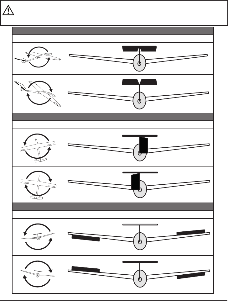
WARNING: once you have completed this procedure, it is absolutely essential to check that
all the gyros are working in the correct direction. This is accomplished by moving the model
around all three axes in turn, and checking the control surface deections - see diagrams
below. You must not y the model before doing this: crash hazard!
ELEVATOR
Model movement Control surface response (seen from the tail)
RUDDER
Model movement Control surface response (seen from the tail)
AILERON
Model movement Control surface response (seen from the tail)
Manual Receiver GR-24PRO 3xG+3A+3M+Vario Graupner HoTT 2. 4 29
4. PROGRAMMING THE GYRO SETTINGS:
PID (Proportional Integral Differential) correction
The stabilising effect of the gyro sensors is based fundamentally on three parameters:
P factor: denes proportional correction
P = proportional: if the intended value is not the same as the actual value, then the difference is fed
proportionally into the corrective signal; in simple terms, the input value (e) is multiplied by a xed
value: u(t) = Kp*e(t). Kp is termed the amplication value. The output value is therefore proportional to
the gyro’s input value. Proportional correction cannot occur until a deviation from the intended value is
present; if the deviation is 0, then the product is also zero. If the amplication value is set too high, the
P factor causes the model to oscillate and become unstable.
I factor: integral correction (not currently implemented)
D factor: denes differential correction
D = differential: in this case the corrective output value is affected by the rate of change of the input
value, i.e. the faster the model tilts around the axis, the more pronounced the corrective response of the
gyro. If the model changes attitude very gently, then the D factor causes hardly any corrective action. It
also makes absolutely no difference how far the model has already changed attitude; the crucial value
is only the speed or rate of the movement. The rate of change is again multiplied by a factor (as with P
correction) to produce the output value. For this reason pure D correction is not used; it must always be
employed in combination with P correction.
4.1 Programming PID correction - Gyro settings display:
CAUTION: before you start entering settings for a new model, it is essential to select the
number of aileron servos in the Aileron servos menu point, and to dene the gyro axes and
orientation in the New settings menu point.
Aileron / Elevator / Rudder: shows the programmable P factors for the corresponding control surface.
Note: the gyro axes must rst be dened under New settings (see section 3.4).
If you wish to disable the gyro, enter the value OFF in the appropriate control function.
P factor:
The P factor should always be set rst, followed by the D factor (adjustment range in each case 0 to 10).
A general rule is that the larger the control surface, the smaller the P factor required. Start with a factor
of 2 (default setting), and do not exceed 4 - 5 as maximum value for the normal ight phase, 2 - 3 for
speed, 3 - 6 for landing; the maximum value of 10 should be reserved for torque-rolls only.
WARNING: if you program separate ight phases, it is essential to select the appropriate
ight phase when the model is in the air, as inappropriate gyro settings may cause the control
surfaces to oscillate, possibly resulting in the loss of the model!
Note: the higher the model’s speed, the more quickly oscillation may set in.
D factor: for a given P factor setting, the model’s tendency to oscillate can be reduced by setting a lower
D factor. However, if you select a lower setting for the P factor, then you may be able to set a higher
D factor value before the onset of control surface oscillation. The gyro effect can be optimised by ne-
tuning the D factor.

30 Manual Receiver GR-24PRO 3xG+3A+3M+Vario Graupner HoTT 2.4
Note: the standard P and D values should cause the gyros to correct the model’s attitude quickly when
it is upset by an outside inuence, without causing oscillation, but in practice the optimum values for a
particular model can only be found by ight-testing. If the model displays little or no automatic stabilisation
with the default settings, the value should be raised; on the other hand, if the model oscillates (wave-like
movements in ight), the value should be reduced.
If your transmitter has spare proportional controls, you can use them to adjust the values while the
model is ying.
Some transmitters allow the corrective factors to be altered during a ight using the proportional controls,
whereas others allow xed values only.
4.2 Programming the factors
4.2.1 Programming, transmitter with proportional controls
If your HoTT transmitter is equipped with proportional controls, it is also possible to adjust the P and
D factors for each axis during a ight: what you might call ‘ying the settings’. You need to assign
proportional controls (e.g. the sliders on the mc-20) to any channel in the range 5 to 16 (in this example
channel 9); now you can alter the P factor (and the D factor) using these controls. In each case the
current values are shown in brackets.
Procedure, using the ailerons as an example:
• Move the cursor to the appropriate line, in this case “Ail” for
aileron.
• Press the SET button to activate the Channel eld.
• Select the appropriate channel, and save the setting with
pressing the SET button again
• move the corresponding proportional control to alter the factor
(adjustment range 0 - 10; 0 means no gyro correction for that
axis).
• You can also adopt this factor directly by pressing the left
button < or the right button >. This frees up the channel previously occupied by the proportional
control, so that it can be used for some other purpose, e.g. for elevator or rudder.
• Move on to elevator and / or rudder, and select the channel and factor (you can either select the
same channel, in order to alter all the axes simultaneously, or different channels, allowing you to
program the axes individually).
• Move the cursor to the Factor line, where you can also change the P factor for aileron, elevator
and rudder with priority (adjustment range up to 200%).
• Move the cursor to the D factor line, where you can alter the D factor for aileron, elevator and
rudder with priority using a proportional control (adjustment range up to 200%; channel value
-100% equates to a factor of 0%, channel value 0% equates to 100%, and +100% equates to
200%). This makes it a very easy matter to match the gyro’s corrective effect to the model’s
airspeed. In particular, higher gyro gain can be used for the landing approach - without the need
to switch ight phases.
• Now test-y your model and ne-tune the values one by one until your preferred stabilising effect
is achieved without the model oscillating.
• It may be sensible or easier to activate the gyro for one axis only at rst, and then to establish the
optimum setting for that axis, rather than for several axes simultaneously.
GYRO SETTINGS < >
>AILERON:
>ELEVATOR:
>RUDDER:
COEFF.:
COEFF. D:
(2)K9
(3)K8
6
(44%)K10
(140%)K11
Manual Receiver GR-24PRO 3xG+3A+3M+Vario Graupner HoTT 2. 4 31
4.2.2. Programming, transmitter without proportional controls
• Move the cursor to the appropriate line, in this case “Ail” for
aileron.
• Press the SET button to activate the Channel eld, select the
appropriate value (1 - 10 of OFF), then press the SET button
to save it.
• First select a low value (see P factor section for starting points)
and carry out a test-ight. If gyro stabilisation is not
sufciently pronounced, increase the value step by step
until the level of correction is as required; if the model
already oscillates, reduce the value step by step.
• Do not select a channel (Ch5 - Ch16); this function is only relevant to transmitters with proportional
controls.
• Move on to elevator or rudder and select the desired value (or OFF).
• Leave the settings for “Factor” and “Factor D” at OFF.
• It may be sensible or easier to activate the gyro for one axis only at rst, and then to establish the
optimum setting for that axis, rather than for several axes simultaneously.
Once you have found the optimum settings, you can set up a transmitter switch to control the gyro, i.e.
for switching between gain settings. For example, you could assign a three-position switch to “Factor”
and “Factor D”, and then use it to switch the values between 0% (OFF), 100% and 200%.
Flight phase specic settings
It is possible to use a channel to control the factor value by setting up ight phase specic transmitter
control settings, but only if the transmitter is an MX20 / MC20 or MC32; please see the instructions
supplied with your transmitter and refer to the “Transmitter control settings” and “Flight phase settings”
menu points for more information.
4.3 Initialising the gyro
After switching on the model of the gyroscope is immediately active but not yet initialized. To initialize it,
you keep your model when switching quiet and straight in level ight - the best place it on the at ground
or a at table. After about 2 seconds, the ailerons move up and down just once. This “wiggle” signaled
the successful initialization, the end of the calibration, only then the model may be moved again.
All sticks are to be kept strictly in neutral!
WARNING: during the initialisation phase the gyro detects the model’s neutral attitude, and for
this reason it is absolutely essential to leave the model in its ‘normal ight attitude’ during the
activation phase, and avoid moving it! If you neglect this, the gyro may detect an incorrect ight
attitude, with the result that the model will not y as you expect it to. It may be difcult to control,
and could even crash!
During the initialisation phase the receiver also detects the centre points of the individual control
channels; this information is used for gyro suppression. Gyro suppression reduces the stabilising
action progressively as the transmitter controls are deected away from centre; at +/- 100% the
gyro is completely disabled.
Your model is now ready to y .. !
GYRO SETTINGS < >
>AILERON:
>ELEVATOR:
>RUDDER:
COEFF.:
COEFF. D:
2
4
6
Aus
Aus
32 Manual Receiver GR-24PRO 3xG+3A+3M+Vario Graupner HoTT 2. 4
5. FIRMWARE UPDATE - GRAUPNER GR-24PRO 3xG+3A+3M+Vario - 33583 HOTT RECEIVER
Firmware updates are loaded into the receiver via the Channel 5 output, using a PC running Windows
XP, Vista or 7. You will also need the separately available USB interface, Order No. 7168.6 and the
adapter lead, Order No. 7168.6A or 7168.S (33575: additional adapter lead, Order No. 33565.1).
The programs and les required for this can be found in the Download area for the corresponding
products at www.graupner.de.
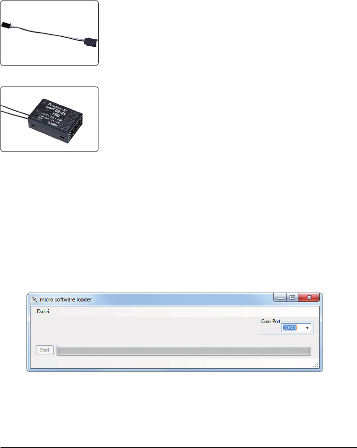
Connect the adapter lead to the USB interface, Order No. 7168.6. The
connectors are polarised: note the small chamfers on one side. Never
use force - the connectors should engage easily.
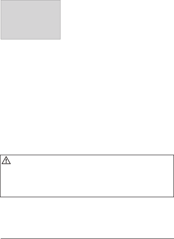
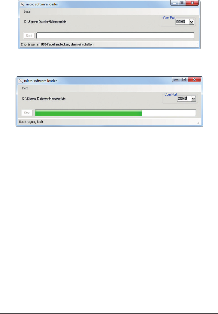
5.1 Receiver
GR-24PRO 3xG+3A+3M+Vario HoTT receiver / (Order No. 33583):
Connect the adapter lead to receiver as shown in the picture. The
connectors are polarised: note the small chamfers on one side. Never
use force - the connectors should engage easily.
The black wire must be at the top (-), the orange wire at the bottom (T).
5.2. Update procedure
Start “Slowyer/Gyro receiver update”
The “Slowyer/Gyro receiver update” program is best called up from the “Firmware_Upgrade_grStudio”
program. Click on the “Slowyer/Gyro receiver update” point under “Link” in the left-hand function menu
(alternatively select the appropriate entry “Micro Receiver Upgrade” under “Menu”).
It is also possible to start the associated application program directly by double-clicking on the le
“micro_gyro_swloader.exe”. You will nd this .exe le in the “Graupner_PCSoftware” folder of the
“HoTT_Software VX” package.
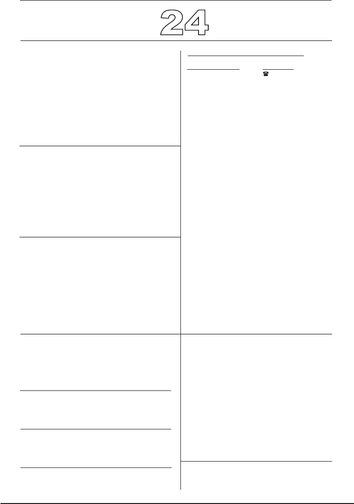
A program window now appears in which you should rst set the “correct” COM port for the USB
interface, Order No. 7168.6, in the Select window.
If you are not sure of this, check the COM port in the “Select Port” window in the “Controller Menu”
(see above), and note down the COM port number at the “Silicon Labs CP210x USB to UART Bridge”
entry – in this case “COM03” (if you select the wrong port, you will be alerted to this when you read out
the receiver data). Click on xx in order to load the corresponding rmware le named “MicroStabi7X_V_
XX.bin” from the hard disc (“XX” stands for the version number.)
Manual Receiver GR-24PRO 3xG+3A+3M+Vario Graupner HoTT 2. 4 33
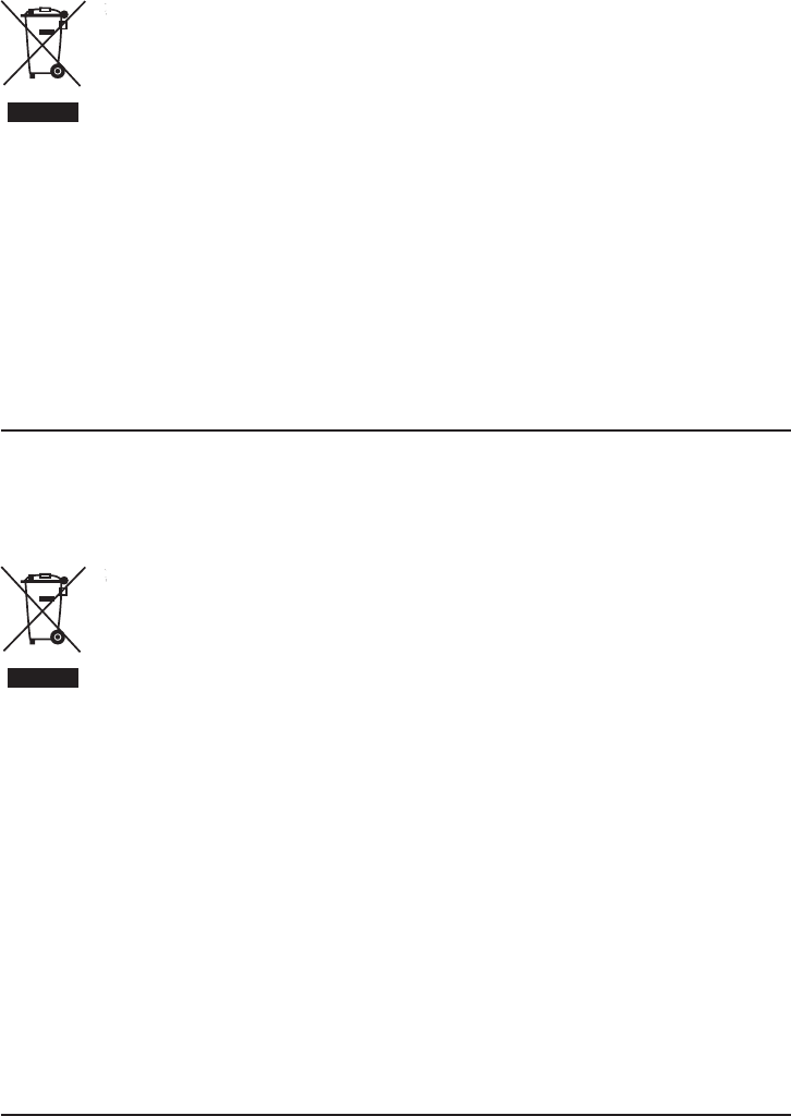
When the le has loaded, click on Start …
… connect the receiver, and switch it on.
The progress bar shows the transfer proceeding normally. The receiver LED is off during this period,
then ashes as soon as the le transfer is complete.
Please refer to the detailed update instructions in the Download area for the corresponding item at
http://www.graupner.de.
A
B
D

GR-24PRO 3xG+3A+3M+Vario Graupner HoTT 2. 4
Konformitätserklärung gemäß dem Gesetz über Funkanlagen und
Telekomunikationsendeinrichtungen (FTEG) und der Richtlinie 1999/5/EG (R&TTE)
Declaration of Conformity in accordiance with the Radio and Telecomunikations Terminal Equipment
Act (FTEG) and Directive 1999/5/EG (R&TTE)
Graupner/SJ GmbH
Henriettenstraße 96
D-73230 Kirchheim/Teck
erklärt, dass das Produkt:
declares that the product
Geräteklasse: 1
Equipment class
den grundlegenden Anforderungen des § 3 und den übrigen einschlägigen Bestimmungen des
FTEG (Artikel 3 der R&TTE) entspricht.
complies with the essential requirements of § 3 and the other relevant provisions of the FTEG (Article 3 of the
R&TTE Directive).
Angewendete harmonisierte Normen:
Harmonised standards applied
EN 60950-1:2006+A11:
2009+A1:2010+A12:
2011
EN 301 489-1 V1.9.2
EN 301 489-17 V2.1.1
EN 300 328 V1.7.1
Health and safety requirements pursuant to § 3 (1) 1. (Article 3 (1) a))
Protection requirement concernig electromagnetic compatibility
§ 3 (1) 2, Artikel 3 (1) b))
Measures for the efficient use of the radio frequency spectrum
§ 3 (2) (Article 3 (2))
Kirchheim, 17. April 2013 Ralf Helbing, Geschäftsführer
Ralf Helbing, Managing Director
Graupner/ SJ GmbH Henriettenstraße 96 D-73230 Kirchheim/Teck Germany
Tel: 07021/722-0 EMail: info@graupner.deFax: 07021/722-188
Gesundheit und Sicherheit gemäß § 3 (1) 1. (Artikel 3 (1)a))
Schutzanforderungen in Bezug auf elektromagnetische
Verträglichkeit § 3 (1) 2, Artikel 3 (1) b))
Maßnahmen zur effizienten Nutzung des Frequenzspektrums
§ 3 (2) (Artikel 3 (2))
GR-24 PRO +3xG + 3A + 3M HoTT - No. 33583
50
6. Konformitätserklärung / Garantie /Herstellererklärung / Entsorgungshinweise
6. Conformity declaration / Guarantee / Manufacturer’s declaration / Disposal
6. Certi cat de conformité/Garantie/Déclaration fabricant/Recyclage/Environnement

GR-24PRO 3xG+3A+3M+Vario Graupner HoTT 2. 4 51
Herstellererklärung
Inhalt der Herstellererklärung:
Sollten sich Mängel an Material oder Verarbeitung an einem von uns in der Bundesrepublik Deutschland vertriebenen, durch
einen Verbraucher (§ 13 BGB) erworbenen Gegenstand zeigen, übernehmen wir, die Fa. Graupner GmbH & Co KG, Kirch-
heim/Teck im nachstehenden Umfang die Mängelbeseitigung für den Gegenstand.
Rechte aus dieser Herstellererklärung kann der Verbraucher nicht geltend machen, wenn die Beeinträchtigung der Brauch-
barkeit des Gegenstandes auf natürlicher Abnutzung, Einsatz unter Wettbewerbsbedingungen, unsachgemäßer Verwendung
(einschließlich Einbau) oder Einwirkung von außen beruht.
Diese Herstelwlererklärung lässt die gesetzlichen oder vertraglich eingeräumten Mängelansprüche und –rechte des Verbrau-
chers aus dem Kaufvertrag gegenüber seinem Verkäufer (Händler) unberührt.
Umfang der Garantieleistung
Im Garantiefall leisten wir nach unserer Wahl Reparatur oder Ersatz der mangelbehafteten Ware. Weitergehende Ansprüche,
insbesondere Ansprüche auf Erstattung von Kosten im Zusammenhang mit dem Mangel (z.B. Ein-/Ausbaukosten) und der
Ersatz von Folgeschäden sind – soweit gesetzlich zugelassen – ausgeschlossen. Ansprüche aus gesetzlichen Regelungen,
insbesondere nach dem Produkthaftungsgesetz, werden hierdurch nicht berührt.
Voraussetzung der Garantieleistung
Der Käufer hat den Garantieanspruch schriftlich unter Beifügung des Originals des Kaufbelegs (z.B. Rechnung, Quittung,
Lieferschein) und dieser Garantiekarte geltend zu machen. Bei Fahrtenreglern muss der verwendete Motor mit eingeschickt
werden und die verwendete Zellenzahl angegeben werden, damit die Ursache für den Defekt untersucht werden kann. Der
Käufer hat zudem die defekte Ware auf seine Kosten an die o.g. Adresse einzusenden. Die Einsendung hat an folgende
Adresse zu erfolgen:
Fa. Graupner/SJ GmbH, Serviceabteilung,
Henriettenstr.96, D 73230 Kirchheim/Teck
Serviceabteilung: Tel. 07021/722-130
Der Käufer soll dabei den Material- oder Verarbeitungsfehler oder die Symptome des Fehlers so konkret benennen, dass eine
Überprüfung unserer Garantiepicht möglich wird.
Der Transport des Gegenstandes vom Verbraucher zu uns als auch der Rücktransport erfolgen auf Gefahr des Verbrauchers.
Gültigkeitsdauer
Diese Erklärung ist nur für während der Anspruchsfrist bei uns geltend gemachten Ansprüche aus dieser Erklärung gültig. Die
Anspruchsfrist beträgt 24 Monate ab Kauf des Produktes durch den Verbraucher bei einem Händler in der Bundesrepublik
Deutschland (Kaufdatum). Werden Mängel nach Ablauf der Anspruchsfrist angezeigt oder die zur Geltendmachung von Män-
geln nach dieser Erklärung geforderten Nachweise oder Dokumente erst nach Ablauf der Anspruchsfrist vorgelegt, so stehen
dem Käufer keine Rechte oder Ansprüche aus dieser Erklärung zu.
Verjährung
Soweit wir einen innerhalb der Anspruchsfrist ordnungsgemäß geltend gemachten Anspruch aus dieser Erklärung nicht an-
erkennen, verjähren sämtliche Ansprüche aus dieser Erklärung in 6 Monaten vom Zeitpunkt der Geltendmachung an, jedoch
nicht vor Ende der Anspruchsfrist.
Anwendbares Recht
Auf diese Erklärung und die sich daraus ergebenden Ansprüche, Rechte und Pichten ndet ausschließlich das materielle
deutsche Recht ohne die Normen des Internationalen Privatrechts sowie unter Ausschluss des UN-Kaufrechts Anwendung.

GR-24PRO 3xG+3A+3M+Vario Graupner HoTT 2. 4
52
Manufacturer’s declaration
Content of the manufacturer’s declaration
If material defects or manufacturing faults should arise in a product distributed by us in the Federal Republic of Germany
and purchased by a consumer (§ 13 BGB), we, Graupner/SJ GmbH, D-73230 Kirchheim/Teck, Germany, acknowledge the
obligation to correct those defects within the limitations described below.
The consumer is not entitled to exploit this manufacturer’s declaration if the failure in the usability of the product is due to natural
wear, use under competition conditions, incompetent or improper use (including incorrect installation) or external inuences.
This manufacturer’s declaration does not affect the consumer’s legal or contractual rights regarding defects arising from the
purchase contract between the consumer and the vendor (dealer).
Extent of the guarantee
If a claim is made under guarantee, we undertake at our discretion to repair or replace the defective goods. We will not
consider supplementary claims, especially for reimbursement of costs relating to the defect (e.g. installation / removal costs)
and compensation for consequent damages unless they are allowed by statute. This does not affect claims based on legal
regulations, especially according to product liability law.
Guarantee requirements
The purchaser is required to make the guarantee claim in writing, and must enclose original proof of purchase (e.g. invoice,
receipt, delivery note) and this guarantee card. The purchaser must send the defective goods to us at his own cost, using the
address stated below.
Graupner/SJ GmbH, Service Department,
Henriettenstr.96, D 73230 Kirchheim/Teck, Germany
Service Department: tel. [0049] 7021-722130
The purchaser should state the material defect or manufacturing fault, or the symptoms of the fault, in as accurate a manner
as possible, so that we can check if our guarantee obligation is applicable.The goods are transported from the consumer to us
and from us to the consumer at the risk of the consumer.
Duration of validity
This declaration only applies to claims made to us during the claim period as stated in this declaration. The claim period is 24
months from the date of purchase of the product by the consumer from a dealer in the Federal Republic of Germany (purchase
date). If a defect arises after the end of the claim period, or if the evidence or documents required according to this declaration
in order to make the claim valid are not presented until after this period, then the consumer forfeits any rights or claims from
this declaration.
Limitation by lapse of time
If we do not acknowledge the validity of a claim based on this declaration within the claim period, all claims based on this
declaration are barred by the statute of limitations after six months from the time of implementation; however, this cannot occur
before the end of the claim period.
Applicable law
This declaration, and the claims, rights and obligations arising from it, are based exclusively on the pertinent German Law,
excluding the norms of international private law, and excluding UN retail law.

Déclaration fabricant
Contenu de la déclaration fabricant:
Si une pièce, que nous avons mise sur le marché allemand, devait présenter un défaut ou un vice caché, matériel ou autre
(conformément au § 13 BGB), nous, Sté Graupner/SJ GmbH, Kirchheim/Teck, nous nous engageons à la remplacer dans
le cadre ci-dessous.
Le consommateur (client) ne peut faire valoir les droits de cette déclaration, si la pièce en question a fait l’objet d’une usure
normale, si elle a été utilisée dans des conditions anormales, si son utilisation n’est pas conforme (y compris le montage) ou
si elle a été sujette à des inuences extérieures. Cette déclaration ne change en rien les droits du consommateur (client) vis
à vis de son détaillant (revendeur).
Etendue de la garantie
Dans le cas d’une prise en charge au titre de la garantie, nous nous réservons le droit, soit de remplacer la pièce en question,
soit de la réparer. D’autres revendications, en particulier, les coûts (par ex. de montage ou de démontage) liés de la pièce
défectueuse et un dédommagement des dégâts engendrés par cette pièce sont exclus du cadre légal. Les droits issus des
différentes législations, en particulier, les réèles de responsabilités au niveau du produit, ne sont pas remises en cause.
Conditions de garantie
L’acheteur peut faire valoir la garantie, par écrit, sur présentation de la preuve d’achat originale (par ex. facture, quittance,
reçu, bon de livraison). Dans le cas de variateurs, il faut joindre le moteur utilisé avec indication du nombre d’éléments de
l’accu pour que l’origine du dysfonctionnement puisse être examiné. Les frais d’envoi, à l’adresse ci-dessous, restant à sa
charge:
Fa. Graupner/SJ GmbH,
Serviceabteilung,
Henriettenstr.96, D 73230 Kirchheim/Teck
Serviceabteilung: Tel. 07021/722-130
Par ailleurs, l’acheteur est prié de décrire le défaut ou dysfonctionnement constaté de la manière la plus explicite et la plus
concrète possible, de sorte que nous puissions vérier la possibilité de la prise en charge au titre de la garantie.
Les marchandises voyagent toujours aux risques et périls du client, qu’il s’agisse de l’expédition du client vers nos services
ou l’inverse.
Durée de la garantie
La durée de la garantie est de 24 mois, à partir de la date d’achat, et achat effectué sur le territoire allemand. Si des
dysfonctionnements ou dommages devaient être constatés au delà de cette durée, ou si des déclarations de non-conformité
devaient nous parvenir au delà de cette date, même avec les preuves d’achat demandées, le client perd tout droit à la
garantie, malgré la déclaration de conformité ci-dessus.
Prescription
Tant que nous n’avons pas reconnu le bien fondé d’une réclamation, il y a prescription au bout de 6 mois, à partir de la date
de la réclamation, néanmoins, pas avant la date d’expiration de la garantie.
Droit applicable
A cette déclaration et des réclamations, des droits et des devoirs qui en découlent n’est applicable que le droit allemand,
sans application du droit privé international et exclusion de l’application de la convention des Nations Unies sur les contrats
de vente.
53GR-24PRO 3xG+3A+3M+Vario Graupner HoTT 2. 4
GR-24PRO 3xG+3A+3M+Vario Graupner HoTT 2. 4 54
Graupner-Zentralservice
Servicestellen / Service / Service après-vente
Wir gewähren auf dieses Erzeugnis eine / This product is / Sur ce produit nous accordons une
24
Monaten
months
mois
Garantie-Urkunde
Warranty certifi cate / Certifi cat de garantie
Übergabedatum
Date of purchase/delivery
Date de remise
Name des Käufers
Owner´s name
Nom de I`acheteur
Straße, Wohnort
Complete adress
Adresse complète
Firmenstempel und Unterschrift des Einzelhändlers
Stamp and signature of dealer
Cachet et signature du vendeur
Graupner/SJ GmbH
Henriettenstrasse 96
D-73230 Kirchheim / Teck
Servicehotline
(+49) (0)7021/722-130
Montag - Donnerstag
7:30 -9:00 Uhr
9:15 -16:00 Uhr
Freitag
9:00 - 13:00 Uhr
Garantie von
warrantied for
garantie de
Die Fa.Graupner/SJ GmbH, Henriettenstrasse 96,
73230 Kirchheim/Teck gewährt ab dem Kaufdatum auf
dieses Produkt eine Garantie von 24 Monaten. Die Garantie
gilt nur für die bereits beim Kauf des Produktes vorhandenen
Material- oder Funktionsmängel. Schäden, die auf Abnüt-
zung, Überlastung, falsches Zubehör oder unsachgemäße
Behandlung zurückzuführen sind, sind von der Garantie
ausgeschlossen. Die gesetzlichen Rechte und Gewährleis-
tunsansprüche des Verbrauchers werden durch diese Garan-
tie nicht berührt. Bitte überprüfen Sie vor einer Reklamation
oder Rücksendung das Produkt genau auf Mängel, da wir
Ihnen bei Mängelfreiheit die entstandenen Unkosten in
Rechnung stellen müssen.
Graupner/SJ GmbH, Henriettenstrasse 96,
73230
Kirchheim/Teck, Germany guarantees this product for a
period of 24 months from date of purchase. The guarantee
applies only to such material or operational defects witch
are present at the time of purchase of the product. Damage
due to wear, overloading, incompetent handling or the use
of incorrect accessories is not covered by the guarantee. The
user´s legal rights and claims under garantee are not
affected by this guarantee. Please check the product
carefully for defects before you are make a claim or send the
item to us, since we are obliged to make a charge for our
cost if the product is found to be free of faults.
La société Graupner/SJ
GmbH, Henriettenstrasse 96,
73230 Kirchheim/Teck, Allemagne, accorde sur ce produit
une garantie de 24 mois à partir de la date d´achat. La garan-
tie prend effet uniquement sur les vices de fonction-nement
et de matériel du produit acheté. Les dommages dûs à de
l´usure, à de la surcharge, à de mauvais accessoires ou à
d´une application inadaptée, sont exclus de la garantie.
Cette garantie ne remet pas en cause les droits et préten-
tions légaux du consommateur. Avant toute réclamation et
tout retour du produit, veuillez s.v.p. contrôler et noter
exactement les défauts ou vices.
Die Adressen der Servicestellen außerhalb Deutschlands
entnehmen Sie bitte unserer Webseite www.graupner.de.
For adresses of service points outside of germany please
refer to www.graupner.de/en/.
Pour adresses des points de service situés en dehors de
l'Allemagne s'il vous plaît se référer à www.graupner.de/fr/.
33583 Empfänger GR 24 PRO
3xG+3A+3M+Vario
55GR-24PRO 3xG+3A+3M+Vario Graupner HoTT 2. 4
HINWEISE ZUM UMWELTSCHUTZ
Das Symbol auf dem Produkt, der Gebrauchsanleitung oder der Verpackung weist darauf
hin, dass dieses Produkt bzw. elektronische Teile davon am Ende seiner Lebensdauer
nicht über den normalen Hausmüll entsorgt werden dürfen.
Es muss an einem Sammelpunkt für das Recycling von elektrischen und elektronischen
Geräten abgegeben werden.
Die Werkstoffe sind gemäß ihrer Kennzeichnung wiederverwertbar. Mit der Wiederver-
wendung, der stofichen Verwertung oder anderen Formen der Verwertung von Altgeräten leisten Sie
einen wichtigen Beitrag zum Umweltschutz.
Batterien und Akkus müssen aus dem Gerät entfernt werden und bei einer entsprechenden
Sammelstelle getrennt entsorgt werden.
Bei RC - Modellen müssen Elektronikteile, wie z.B. Servos, Empfänger oder Fahrtenregler aus dem
Produkt ausgebaut und getrennt bei einer entsprechenden Sammelstelle als Elektro-Schrott entsorgt
werden.
Bitte erkundigen Sie sich bei der Gemeindeverwaltung nach der zuständigen Entsorgungsstelle.
ENVIRONMENTAL PROTECTION NOTES
The presence of this symbol on a product, in the user instructions or the packaging, means
that you must not dispose of that item, or the electronic components contained within it, in
the ordinary domestic waste when the product comes to the end of its useful life.
The correct method of disposal is to take it to your local collection point for recycling
electrical and electronic equipment.
Individual markings indicate which materials can be recycled and re-used. You can make an important
contribution to the protection of our shared environment by re-using the product, recycling the basic
materials or re-processing redundant equipment in other ways.
Dry cells and rechargeable batteries must be removed from the device and taken separately to a suitable
battery disposal centre.
In the case of RC models electronic components such as servos, receiver or speed controller must be
removed from the product, and taken separately to the appropriate collection point for electrical waste.
If you don’t know the location of your nearest disposal centre, please enquire at your local council ofce.
GR-24PRO 3xG+3A+3M+Vario Graupner HoTT 2. 4
PROTECTION DE L’ENVORONNEMENT
Le symbole, qui gure sur le produit, dans la notice ou sur l’emballage indique que cet
article ne peut pas être jeté aux ordures ménagères en n de vie.
Il doit être remis à une collecte pour le recyclage des appareils électriques et
électroniques.
Selon leur marquage, les matériaux sont recyclables. Avec ce recyclage, sous
quelque forme que ce soit, vous participez de manière signicative à la protection
de l’environnement.
Les piles et accus doivent être retirés des appareils, et remis à un centre de tri approprié.
Sur des modèles RC, tous les éléments électroniques, tels que les servos, récepteurs ou variateurs
doivent être démonté et recyclé séparément.
Renseignez-vous auprès de votre commune pour connaître les centres de collecte et de tri
compétents.
56
FCC Information
Graupner/SJ
GR-12+3xG+3A+3M+Vario HoTT #33583
FCC ID: SNL-16005800
FCC Statement
This device complies with Part 15C of the FCC 1.
Rules. Operation is subject to the following two
conditions:
(1) This device may not cause harmful
interference.
(2) This device must accept any interference
received, including interference that may cause
un desired operation.
Changes or modifi cations not expressly approved 2.
by the party responsible for compliance could void
the user‘s authority to operate the equipment.
NOTE
This equipment has been tested and found to
comply with the limits for a Class B digital device,
pursuant to Part 15 of the FCC Rules. These limits
are designed to provide reasonable protection against
harmful interference in a residential installation. This
equipment generates uses and can radiate radio
frequency energy and, if not installed and used in
accordance with the instructions, may cause harmful
interference to radio communications. However, there
is no guarantee that interference will not occur in a
particular installation. If this equipment does cause
harmful interference to radio or television reception,
which can be determined by turning the equipment
off and on, the user is encouraged to try to correct
the interference by one or more of the following
measures:
Reorient or relocate the receiving antenna.•
Increase the separation between the equipment •
and receiver.
Connect the equipment into an outlet on a •
circuit different from that to which the receiver is
connected.
• Consult the dealer or an experienced radio/TV
technician for help.
FCC Radiation Exposure Statement
This equipment complies with FCC radiation
exposure limits set forth for un uncontrolled
envirionment. Thisequipment should be installed and
operated with a minimum distance of 20 cm between
the antenna and your body.

57GR-24PRO 3xG+3A+3M+Vario Graupner HoTT 2. 4
Notizen

GR-24PRO 3xG+3A+3M+Vario Graupner HoTT 2. 4 58
Notizen

59GR-24PRO 3xG+3A+3M+Vario Graupner HoTT 2. 4
Notizen

Graupner/SJ GmbH
Henriettenstraße 96
D-73230 Kirchheim/Teck
Germany
www.graupner.de
Änderungen sowie Liefermöglichkeiten vorbehalten. Lieferung durch den Fachhandel. Bezugsquellen
werden nachgewiesen. Für Druckfehler kann keine Haftung übernommen werden.
Specications and availability subject to change. Supplied through specialist model shops only. We will
gladly inform you of your nearest supplier. We accept no liability for printing errors.
Sous réserve de modications et de possibilité de livraison. Livraison uniquement au travers de maga-
sins spécialisés en modélisme. Nous pourrons vous communiquer l’adresse de votre revendeur le plus
proche. Nous ne sommes pas responsables d’éventuelles erreurs d’impression.
Mai 2013 - DE V1.0