GRAUPNER 16006500 2.4GHz Radio Controller User Manual Users manual
GRAUPNER CO., LTD. 2.4GHz Radio Controller Users manual
GRAUPNER >
Users manual

USA
No. S1008
4 channel HoTT 2.4 GHz transmitter
X-8E
Manual
Copyright © Graupner/SJ GmbH

2 / 48 S1008_X-8E_jh_V1

3 / 48
S1008_X-8E_jh_V1
Index
Introduction ..........................................................................5
Service Center .....................................................................5
Intended Use ........................................................................6
Package Content .................................................................6
Technical Data .....................................................................7
Declaration of Conformity ..................................................7
Symbols Explication ............................................................8
Safety Notes ......................................................................... 8
For your safety by handling the battery ................................9
Control Elements and Connections .................................11
Buttons and Switches Layout ..........................................11
Commissioning ..................................................................12
Battery connection ............................................................12
Battery charging ................................................................ 12
Transmitter power switch ..................................................12
Tension Spring Adjustment ..............................................13
Adjusting Steering Wheel Position ..................................13
Converting the Steering Wheel for Left-Handers ...........14
Installing the Steering Wheel Adapter .............................15
RF SET ................................................................................16
Binding .............................................................................16
Channel features (CH FUNCTION) .....................................17
Range test ........................................................................18
Start Display ....................................................................... 19
Main Menu ..........................................................................21
H/W SET .............................................................................21
TELE. (Telemetry Menu) ....................................................22
Setting & Data View ..........................................................22
RF Status View..................................................................22
Voice Trigger .....................................................................23
Device Management .........................................................23
Secret Mode .......................................................................24
Announcements (Voice Update) ........................................24
Language change .............................................................24
Steering wheel and throttle lever calibration .......................25
Interface (BT SPEED) ........................................................25

4 / 48 S1008_X-8E_jh_V1
Display Warnings ...............................................................26
Voltage Display Calibration ..............................................26
Change the Values in an Input Field ................................27
M-SEL (Model Selection) ..................................................27
REVERSE (Servo Reverse) ................................................27
TRIM ...................................................................................27
TRA ADJ (E.P.A.) ................................................................28
DR/EXP (Dual Rate/Exponential) .....................................28
B.R.A. ..................................................................................29
B-MIX ..................................................................................30
TH RESP (Throttle Response) ..........................................30
IDLEUP (Pumping) .............................................................30
PROFILE .............................................................................31
S/SPEED .............................................................................32
START .................................................................................32
TIMER .................................................................................33
SW SET ...............................................................................34
FAIL SAFE ........................................................................... 36
SERVO (S View) .................................................................. 36
P/MIX ..................................................................................37
AUX .....................................................................................38
S/MODE ..............................................................................38
A.B.S ...................................................................................40
Operating Receiver GR-8 .................................................. 41
GR-8 Receiver Telemetry Menu .......................................42
Firmware Update - Transmitter ........................................43
Firmware Update - Receiver ............................................44
Battery Disposal ................................................................45
Care and Maintenance ......................................................45
Warranty .............................................................................45

5 / 48
S1008_X-8E_jh_V1
Introduction
Thank you for purchasing the Graupner X-8E HoTT radio. This
radio will transform the way you have been experiencing surface
radios and add a new level of user experience between you and
your model. The X-8E is easy to use and setup using the TFT
color and touch screen. The voice notifications will even further
enhance your user experience.
You can get more out of your X-8E using our wide selection of
telemetry speed controllers and telemetry ESC’s. All HoTT com-
patible products can be setup and programmed directly wire-
less from the X-8E. No need for computers or programming
boxes!
Check us out regularly on the web for new changes and revi-
sions of our manuals and firmware at www.graupnerusa.com.
This product complies with national and European legal require-
ments.
To maintain product condition and to ensure safe operation, you must
read and follow this user manual and the safety notes before use!
Note
This operating manual is part of the product. It contains important
information concerning operation and handling. Keep these instruc-
tions for future reference. Please pass this on to future owners or
third parties.
Service Center
Graupner USA – OPENHOBBY LLC
3941 Park Dr., Suite 20-571
El Dorado Hills, CA 95762
United States
Phone: (855) 572-4746 x2
Hours: Mon – Fri 9:00am – 4:00pm PST
Email: service@graupnerusa.com
Online Support: www.graupnerusa.com
Graupner Online For service centers, downloads, upgrades and product list, visit
our web site at www.graupnerusa.com.

6 / 48 S1008_X-8E_jh_V1
Intended use
The X-8E HoTT transmitter is an ergonomically and technically
modern 8 function radio control system in 2.4GHzHoTT tech-
nology for ambitious and professional RC car and speedboat
drivers.
The X-8E HoTT transmitter is designed exclusively to be used in
battery-powered, unmanned radio controlled models; any other
use is not allowed. For any improper use no warranty or liability
is accepted.
Read through this entire manual before you attempt to use the
X-8E HoTT transmitter.
Graupner/SJ constantly works on the development of all prod-
ucts; we reserve the right to change the item, its technology and
equipment.
The product is not a toy. It is not suitable for children under
14 years. The operation of the X-8E HoTT transmitter must be per-
formed by experienced modelers. If you do not have sufficient
knowledge about dealing with radio-controlled models, please
contact an experienced model builder or a model club.
Package content
X-8E transmitter
GR-8 Receiver
LiPo battery 1S 5000 mAh
USB update cable set (No.S8500, 7168.S)
Micro SD card
Steering wheel adapter 10 degree and cover
Manual
7 / 48
S1008_X-8E_jh_V1
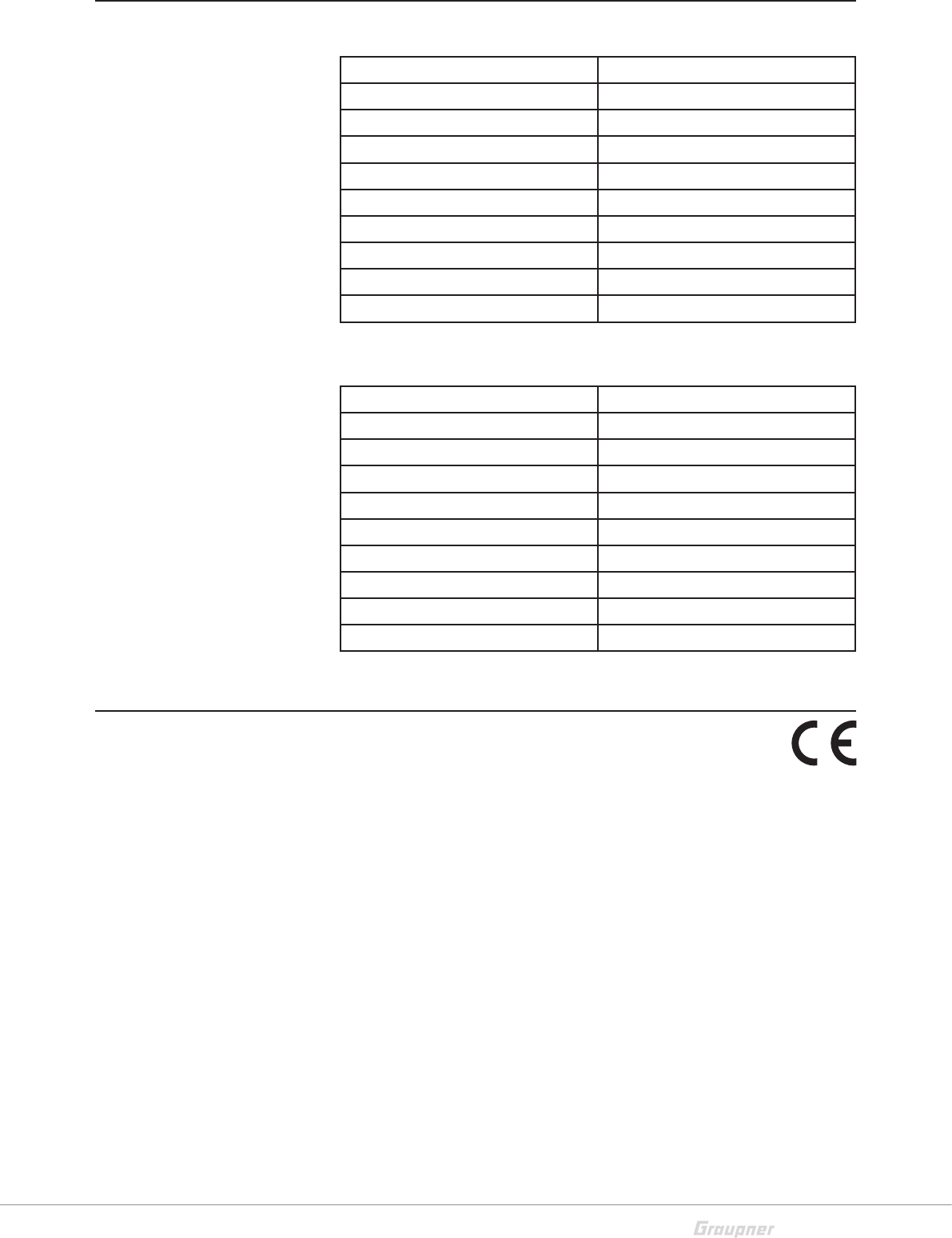
Technical Data
X-8E transmitter data
Operating voltage 3.4 to 6 V
Frequency 2.4 Ghz
Weight 1.44 lb (657 g)
Modulation FHSS
Range 1640 ft (500 m)
Control functions 4
Power consumption max. 600 mA
Temperature range 14° to 130°F (-10 to +55 °C)
Antenna type Patch antenna
Dimensions 8.6 x 7.3 x 5.5 in
GR-8 receiver data
Operating voltage 3.6 to 8.4 V
Frequency 2.4 Ghz
Weight 0.24 oz (6.9 g)
Modulation FHSS
Range 1640 ft (500 m)
Control functions 4
Power consumption 80 mA
Temperature range 14° to 130°F (-10 to +55 °C)
Aerial length 4.3 in (110 mm)
Dimensions 1.18 x 0.82 x 0.56 in
Declaration of conformity
S1008 / X-8E
Graupner/SJ declares that the product is conform to EU norms.
EN 301 489-1 V1.9.2
EN 301 489-17 V2.2.1
EN 300 328 V1.8.1
EN 60950-1:2006 + A11:2009 + A1:2010 + A2:2013
EN 62311:2008
8 / 48
Symbols explication
!
Always observe the information indicated by this warning sign.
Particularly those which are additionally marked with the signal
words CAUTION or WARNING.
WARNING indicates the potential for serious injury.
CAUTION indicates possibility of lighter injuries.
Note indicates potential malfunctions.
Attention indicates potential damages to objects.
Safety notes
General
!
These safety instructions are intended to protect this product,
yourself and the safety of others. Please read this section very
carefully before using this product!
To avoid risk of suffocation, keep packaging materials away from
babies and small children.
Supervision by an experienced adult is required for chil-
dren, persons mentally or physically handicapped, nov-
ices, or anyone not capable of safely using this product.
Always perform a range and function test on the ground
before you use your model (hold your model tight). Repeat
the test with running motor and with short throttle bursts.
Check all relevant laws and regulations before using this
remote control model. These laws and regulations must
be observed in for the safety of yourself and others and
may vary by state, region, or country.
Special liability insurance policies are mandatory for all
device operations. If you already own a device, determine
if the respective model is covered by your insurance.

9 / 48
S1008_X-8E_jh_V1
Protect all equipment from dust, dirt, moisture, vibration and
excessive heat or cold. The models may only be operated
remotely in normal outside temperatures ranging from 14° to
130°F (-10°C to 55°C).
Maintain frequent updates of your HoTT components with
the latest firmware version.
For additional questions or support, contact the Graupner
USA Service Center, or an experienced user.
Battery Safety
CAUTION
Protect batteries from dust, moisture, heat and vibrations.
For use in dry locations only.
Do not use damaged batteries.
Batteries not handled properly may catch fire, explode, or
cause irritation and burns. To extinguish a battery fire use
either water, CO² or sand.
Batteries should not be heated, burned, short-circuited,
incorrectly inserted, modified, soldered or welded.
Charge batteries in a room outfitted with a smoke detec-
tor, on a non-flammable, heat-resistant and non-conduc-
tive surface. Keep away from combustible or highly flam-
mable objects while charging. Always monitor batteries
during the charging process.
Do not exceed the maximum quick-charging current
specified for the respective cell type.
If a battery reaches temperatures above 140°F (60°C)
while it is being charged, immediately stop charging and
let the battery cool down to approximately 86 - 104°F (30
- 40°C).
Never charge batteries that have already been charged,
are hot or are not fully discharged. If a cell in a battery pack
heats up following a quick-charge process, this may indi-
cate a defective cell. Discard the battery immediately!
!

10 / 48 S1008_X-8E_jh_V1
Damaged or corroded batteries may leak an electrolyte
that is caustic and should not be touched or come into
contact with your skin or eyes. In case of emergency,
rinse thoroughly with water and seek immediate
medical attention.
Always fully recharge the battery.
Special instructions on charging LiPo batteries
To charge and discharge LiPo batteries, only use specifi-
cally designed chargers/dischargers with balancer con-
nector.
The white connector (cell count + 1 pole) is designed for
the connection to a LiPo balancer or a battery charger as
a single cell charger with a manual cell balancer. Always
charge the battery with the balancer connector.
Safety notes for stocking LiPo batteries
LiPo batteries should be stored with a voltage of about
3.8V per cell. If the cell voltage falls below 3V, then the bat-
tery must be charged. Fully discharging or storing a bat-
tery with a cell voltage < 3V renders the battery useless.
Exersize safety procautions when charging and transport-
ing your LiPo batteries. Always use a safety bag.
11 / 48
S1008_X-8E_jh_V1
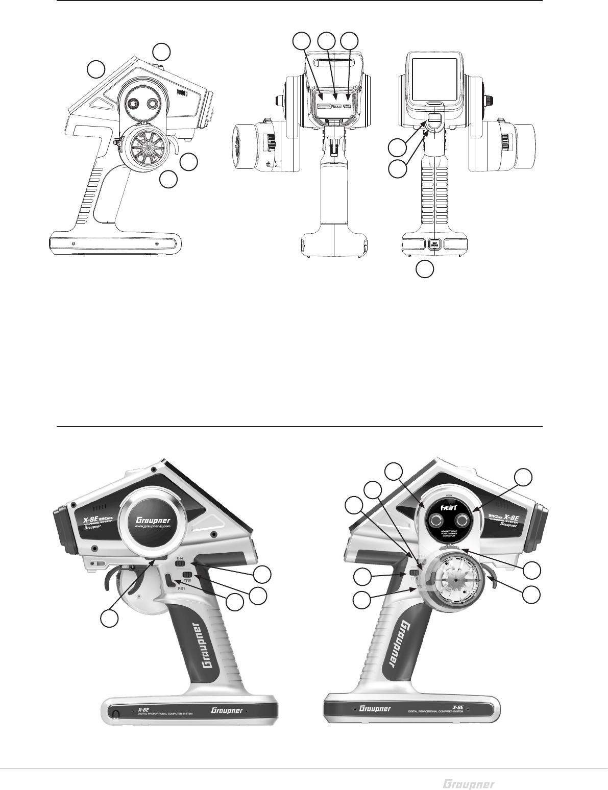
Control Elements and connections
Buttons and Switches Layout
1. Touch Display
2. Steering wheel
3. Throttle lever
4. Earphone socket
5. SD card slot
6. Data socket
7. Mini USB socket
8. On/off switches
9. Direct button S1 (see chapter SW SET)
10. Direct button S2 (see chapter SW SET)
1. PS 1
2. PS 2
3. PS 3
4. DV
5. TR 1
6. TR 2
7. TR 3
8. TR 4
9. TR 5
11
3
2
4
5
6
7
8
8
9
9
1
2
4
5 6 7
8
3
9
10
12 / 48 S1008_X-8E_jh_V1
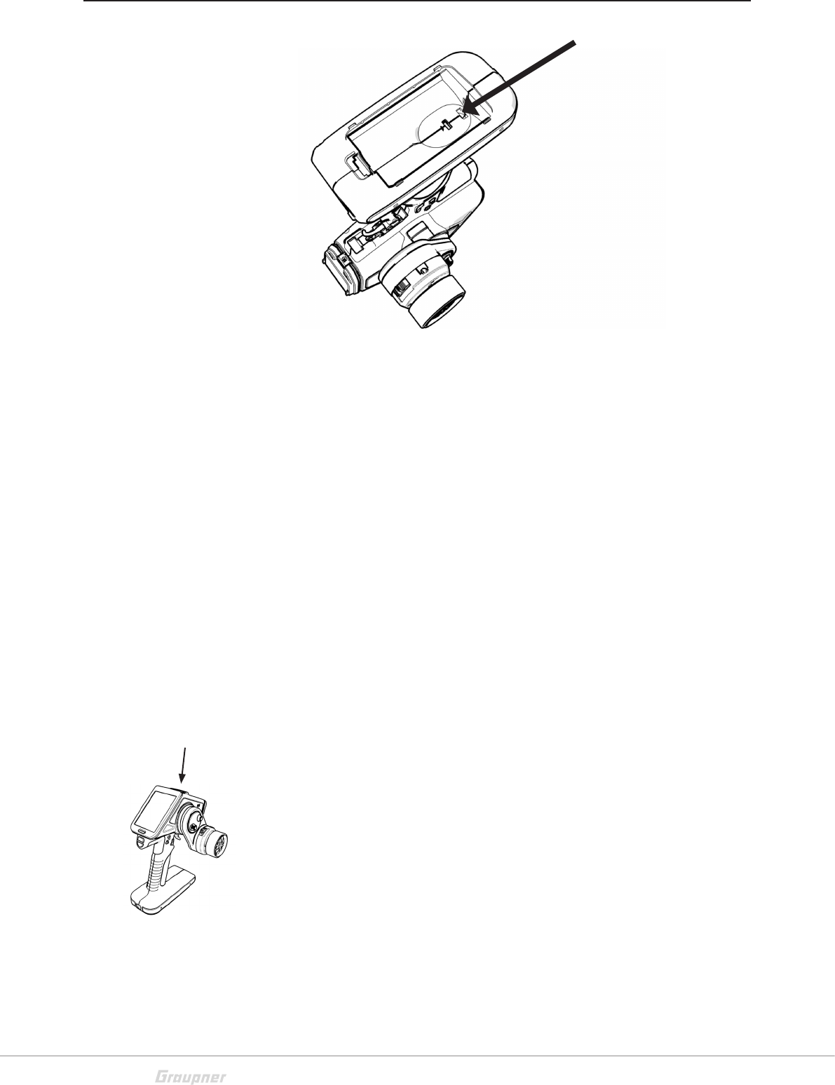
Commissioning
Battery connection
Remove the cover from the bottom of the transmitter and con-
nect the battery, paying attention to the correct polarity. Shut
the cover and ensure it is securely closed.
Set the the battery warning threshold in accordance with the
battery used. (see Chapter “SYS SET”)
If a voltage warning is triggered, charge the batteries.
Battery charging
Charge the LiPo batteries in the transmitter through the micro
USB socket using the USB cable provided. For all other battery
types, use an USB connection, e.g. a PC USB port or an USB
net adapter. During the charging process the LED under the dis-
play lights up red. When the battery is full the LED turns off.
Alternatively, you can charge the battery outside the transmitter
with an RC battery charger (not included).
Transmitter power switch
On the top of the transmitter there are two buttons. To turn on
the transmitter with RF off, push the right button for about 2 sec-
onds. When the RF mode is off, a safety feature is activated that
prevents switched-on models from accidentally starting during
programming. Additionally, power consumption is reduced,
significantly conserving battery life.
To turn on the transmitter with RF on, push the left button.
Battery socket
On - Off
Switch
13 / 48
S1008_X-8E_jh_V1
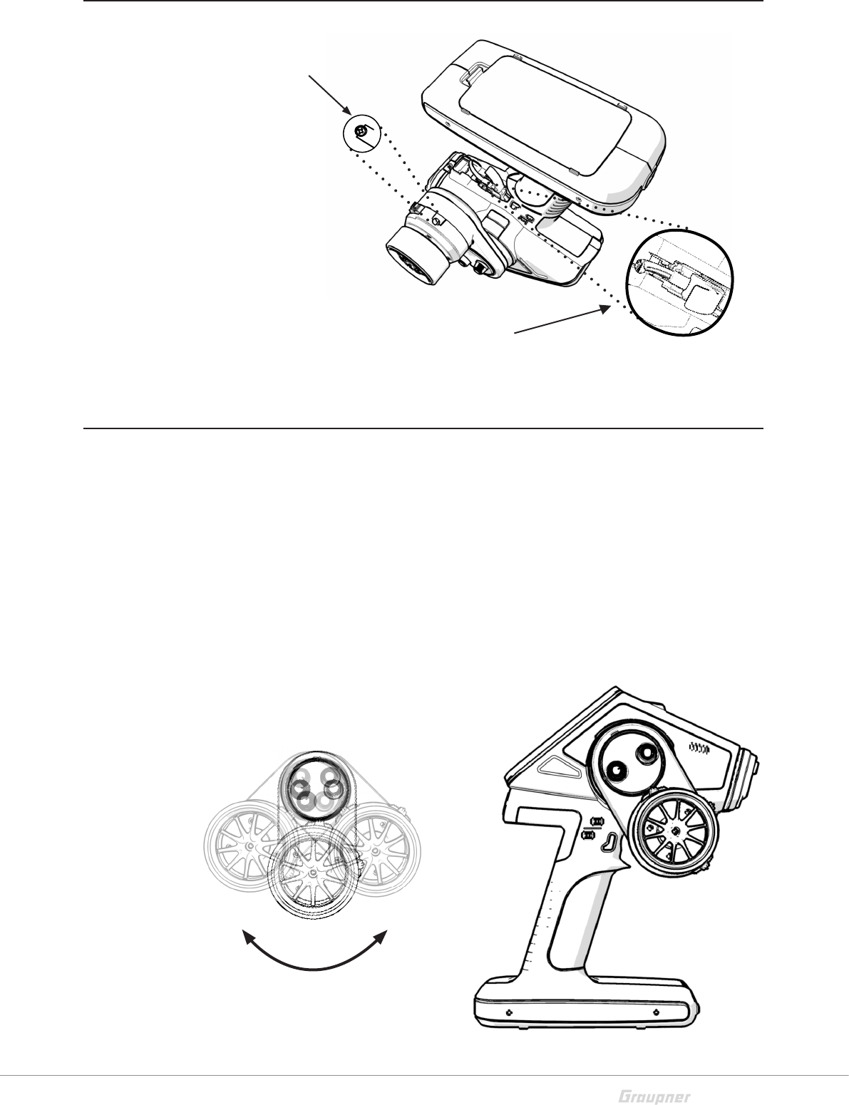
Tension spring adjustment
Adjusting the steering wheel position
To adjust the steering wheel
tension spring, locate the
adjusting screw in the housing
below the wheel.
Using a hex key, turn the
screw left or right to increase
or decrease tension force.
To adjust the throttle lever tension spring, locate the adjusting
screw in the housing at the throttle lever.
Using a hex key, turn the screw left or right to increase or
decrease tension force.
To adjust the steering wheel position forward or backward,
remove the X-8E logo cover, located above the steering wheel.
Loosen the two screws and maneuver the steering wheel into
desired position. Retighten the two screws to secure.
14 / 48 S1008_X-8E_jh_V1
1.
2.
3.
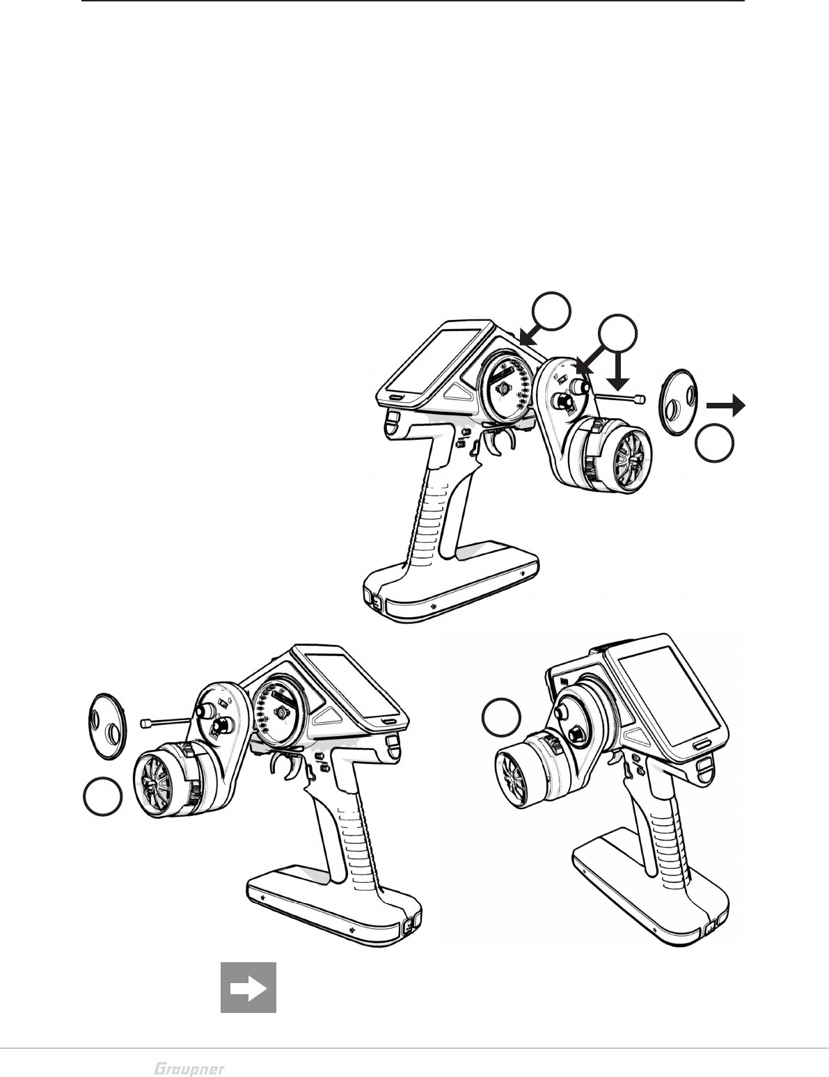
Converting the steering wheel for left-handers
The entire steering wheel can be converted to the left side for
operation by left-handers.
1. Remove the X-8E logo cover (see following figure).
2. Unscrew the steering wheel (2 screws).
3. Unplug the steering wheel cable.
4. Mount the steering wheel on the left side and re-plug the
cable.
5. Tighten the steering wheel and replace the X-8E logo
cover.
4.
Attention After the conversion, check all steering wheel func-
tions, buttons and rotary controls before operating the model
again!
5.
15 / 48
S1008_X-8E_jh_V1
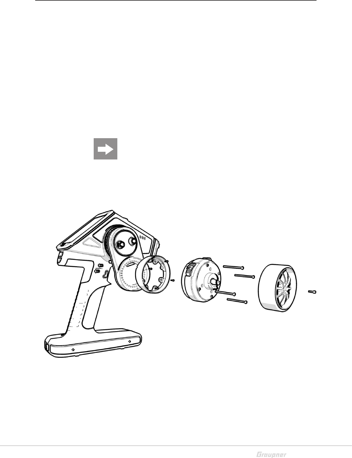
Installing the steering wheel adapter
The steering wheel position can be adjusted 10 degrees through
an adapter.
1. Remove the steering wheel.
2. Remove the four long screws under the wheel.
3. Remove the steering wheel mechanism and disconnect
the connector.
4. Adjust the adapter to preferred position and secure with
the four short screws.
5. Reconnect the connector
6. Install the steering wheel mechanism on the adapter part
and reattatch the steering wheel.
Attention After the conversion, check all steering wheel func-
tions, buttons and rotary controls before operating the model
again!
16 / 48 S1008_X-8E_jh_V1
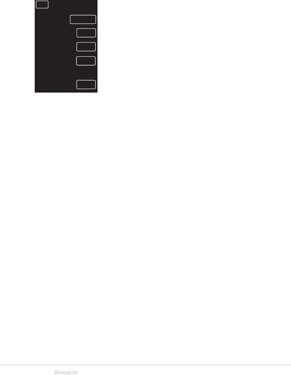
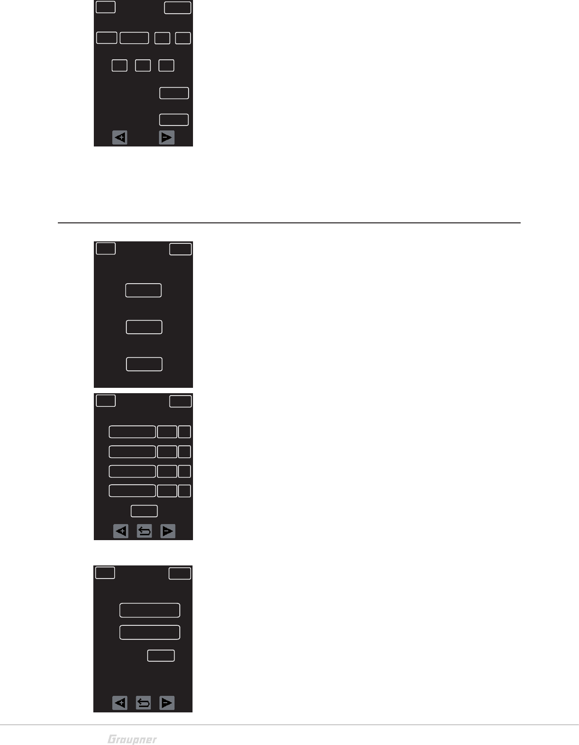
RF SET
Binding and range test
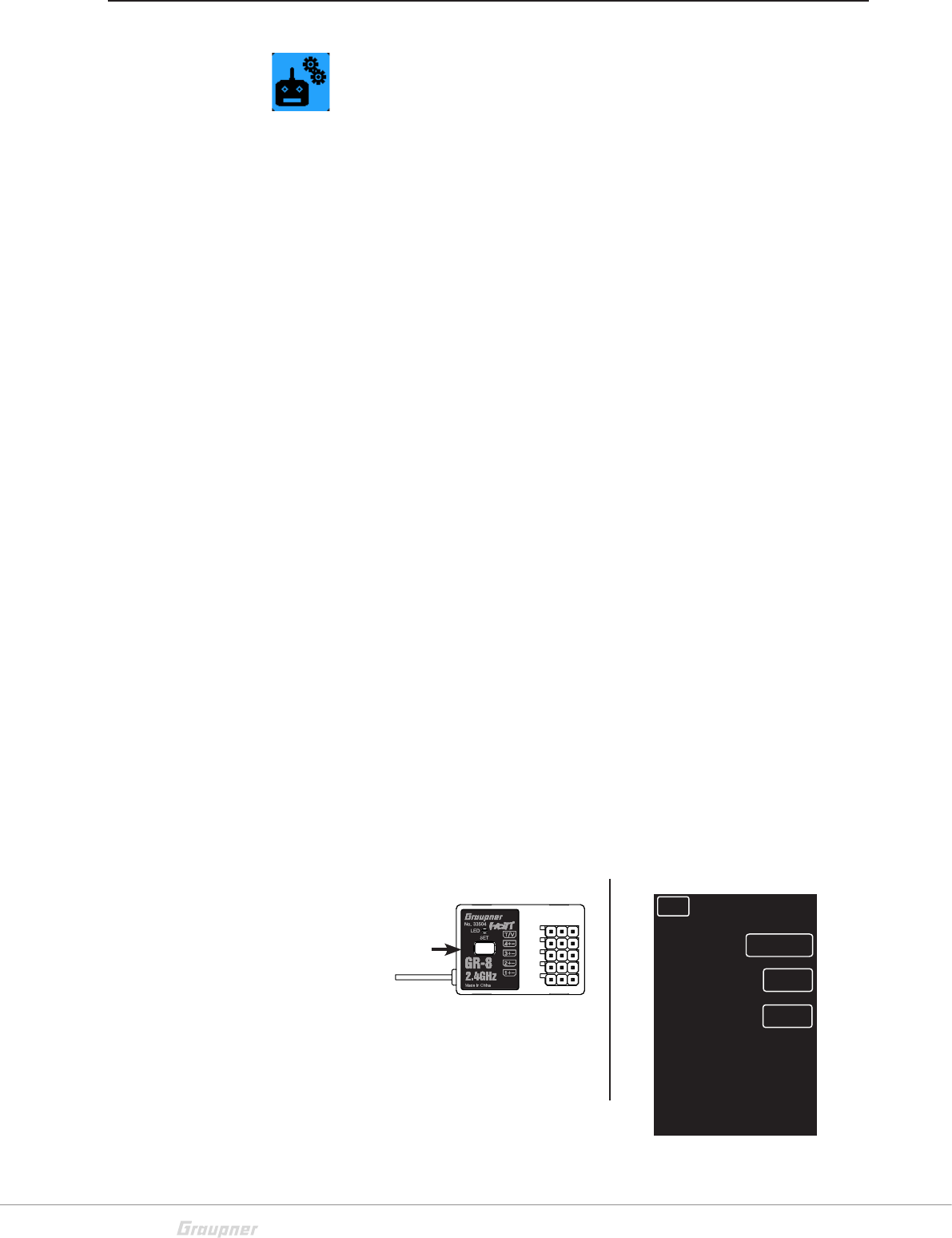
Binding
To establish a communication link, bind the Graupner-HoTT
receiver to the X-8E Graupner-HoTT transmitter. The binding
process has already been performed for the transmitter and the
receiver included. However, binding is required for each addi-
tional receiver added to this transmitter. To bind additional
receivers:
NOTE: The transmitter can be turned ON or OFF with one of
two buttons. When using the white button, the transmitter RF
functions are completely disabled and it will not be possible
to turn on the RF or bind a receiver.
1. Turn on the transmitter using the RED button. If no
receiver is bound to the model, select SET. Selecting SET
will bring up the bind finction of the RF SET menu.
2. Select the correct RF system. (HoTT V2 for the GR-8 or
HoTT for the GR-4.) GR-8: The red LED flashes slowly
when there is no communications link. GR-4: The red
LED glows solid red when there is no communications
link.
3. Press and hold the SET button on the receiver for about
3 seconds.
4. Press the BIND button on the transmitter.
5. The OFF will change to CHK momentarily.
6. If the bind is successful, the number of receiver channels
will be displayed. If not successful, the button will return
to OFF status.
Repeat the bind process until successful. It is all a matter of tim-
ing. (Counting "one thousand one, one thousand two, one
thousand three" will help with the timing.)
Receiver Transmitter display
Binding button
BACK NORMAL
HOTT V2
RF SYSTEM
BIND
TELEMETRY
OFF
ON
17 / 48
S1008_X-8E_jh_V1
Meaning of the individual menu items
RF SYSTEM = HoTT for receiver (GR-4/12/16/18/24/32)
HoTT V2 for receiver with SUMD-V2 (GR-8)
BIND = Displays bound receiver channels
RF ON/OFF = Displays if RF is switched on or off
RANGE TEST = Range test (see chapter “Range test”)
CH FUNCTION ==> (only available in HoTT V2 operation with
compatible receiver)
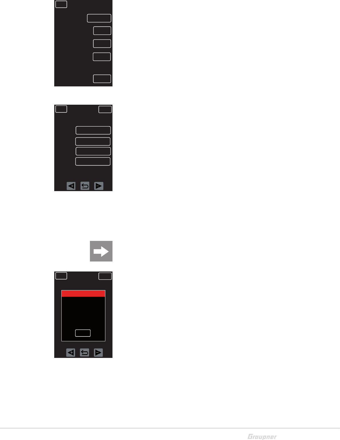
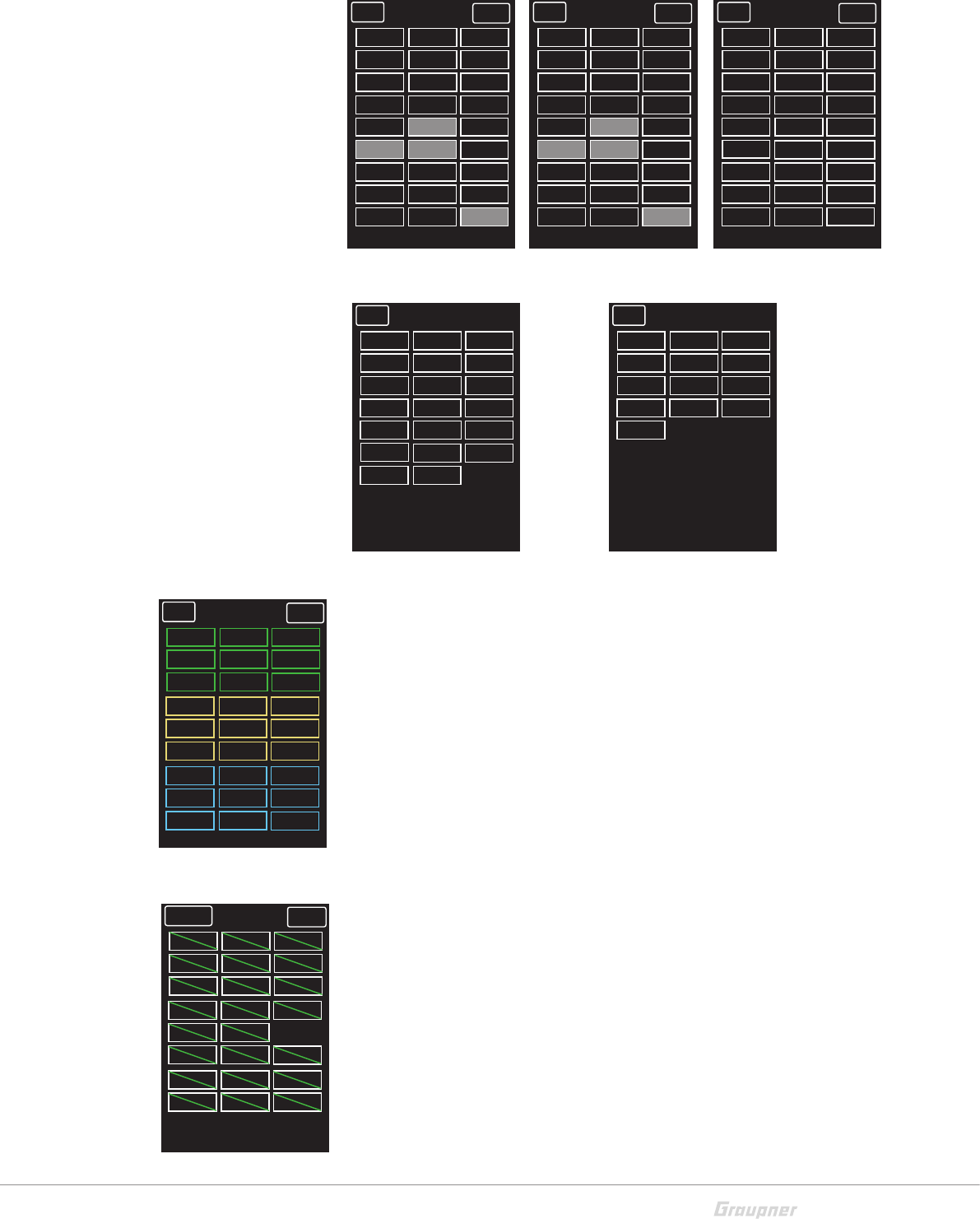
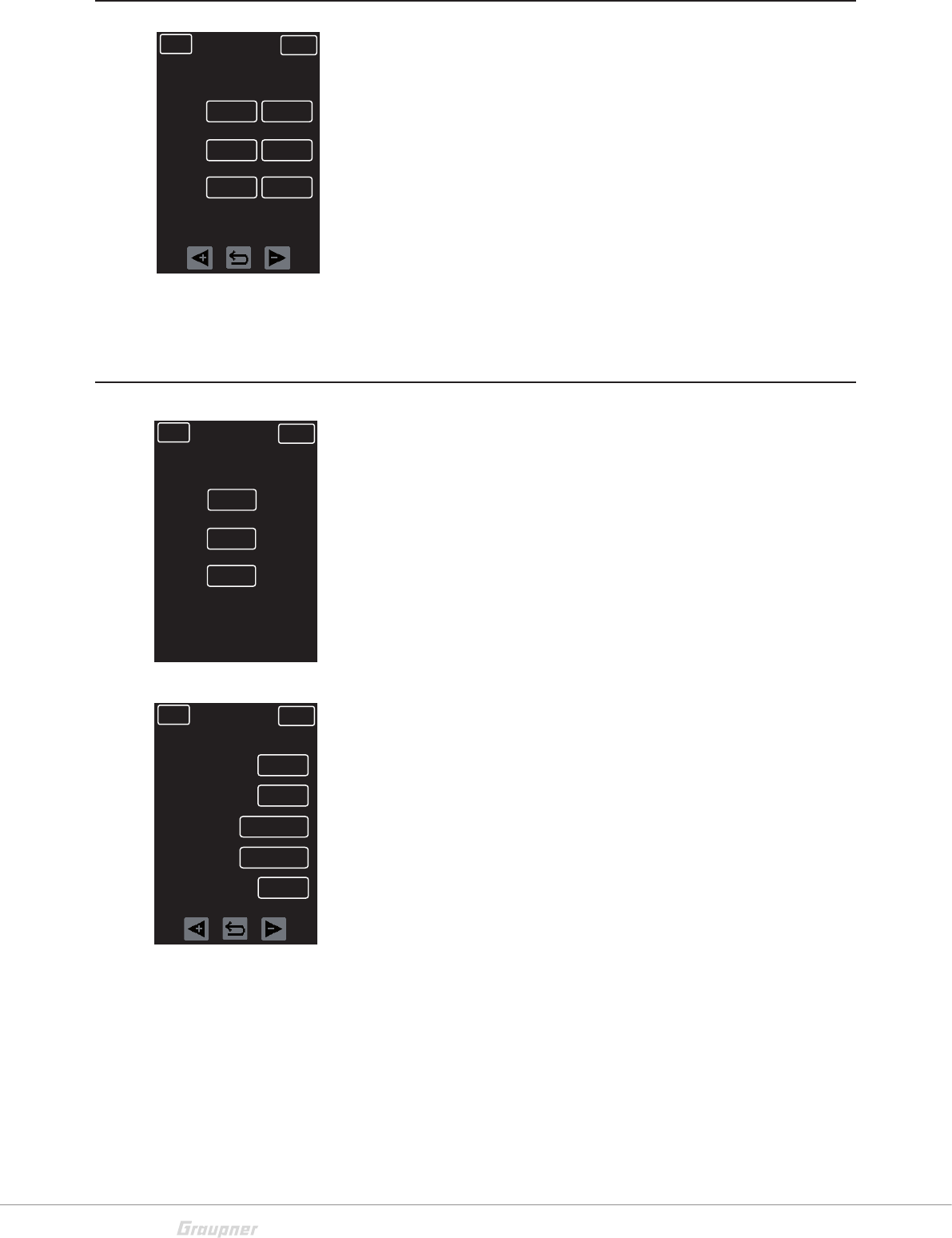
Channel features (CH FUNCTION)
Only available in HoTT V2 operation with compatible receiver!
Each channel is capable of the following signals:
USR1m50 : ULTRA SIGNAL 1.5msec
FSR3m00 : FAST SIGNAL 3.0msec
SUMD-V2 : FAST SIGNAL BUS 3.0msec
NSR6m00 : NORMAL SIGNAL 6.0msec
NSR12m0 : NORMAL SIGNAL 12.0msec
NSR24m0 : NORMAL SIGNAL 24.0msec
Use this menu to adjust the servo properties by setting the indi-
vidual channel properties. (For more information refer to the
servo’s user’s manual.)
Attention
The SUMD-V2 setting can only be used for Graupner servos,
sensors and controllers that support this function!
Notice: To save receiver settings, follow the instructions on the
screen in the following order:
1. Switch receiver off
2. Switch transmitter off
3. Switch transmitter on
4. Switch receiver on
To verify the receiver settings are displayed, check the telemetry
menu.
BACK
NSR12m0
CH 3
NORMAL SERVO
CH 4
CH 2
CH 1
CH FUNCT
NSR12m0
NSR12m0
NSR12m0
BACK NORMAL SERVO
CH FUNCT
Reboot as follows:
1. Power receiver off
2. Switch transmitter off
3. Switch transmitter on
4. Power receiver on
OK
BACK NORMAL
HOTT V2
RF SYSTEM
BIND
RF ON/OFF
R04
ON
RANGE TEST OFF
99sec
CH FUNCTION >>
18 / 48 S1008_X-8E_jh_V1
Range test
Always perform a range test before each operation. Have an
assistant to help with the range test. Range test instructions are
as follows:
1. Bind the receiver with the transmitter and insert into the
model. Switch on the transmitter first, then the receiver.
Servo movements can now be monitored.
2. Place the model on a flat surface (cement, mowed lawn
or level ground) with the receiver antennas at least 6 in (15
cm) above the ground. If necessary, place a support
underneath the model during the test. Hold the transmit-
ter at waist-level at a comfortable distance from your
body. Do not point the aerial directly at the model.
Turn or angle the aerial tip so it stands vertical during oper-
ation. In the “RF SET” menu, press OFF in the “RANGE
TEST” line. This switches the option ON and begins the
range test. The test will ramian active for 99 seconds,
after which it will automatically switch off. (Quit the range
test at any time by pressing ON in the “RANGE TEST” line
to switch this option OFF.)
3. Walk away from the model and turn the wheel to simulate
all servo movements and normal operations. If at any time
you detect an interruption in the link within a range of
about 164 ft (50 m), attempt to reastablish the link.
4. To check interference resistance, switch on an existing
motor. Move away from the model until it no longer
responds. Manually terminate the range test mode.
5. The model should now respond again. If not, do not use
the system and contact the Graupner Service Center.
6. Ground range for safe operation and handling should be
within 164 ft (50 m).
BACK NORMAL
HOTT V2
RF SYSTEM
BIND
RF ON/OFF
R04
ON
RANGE TEST ON
87sec
CH FUNCTION >>
19 / 48
S1008_X-8E_jh_V1
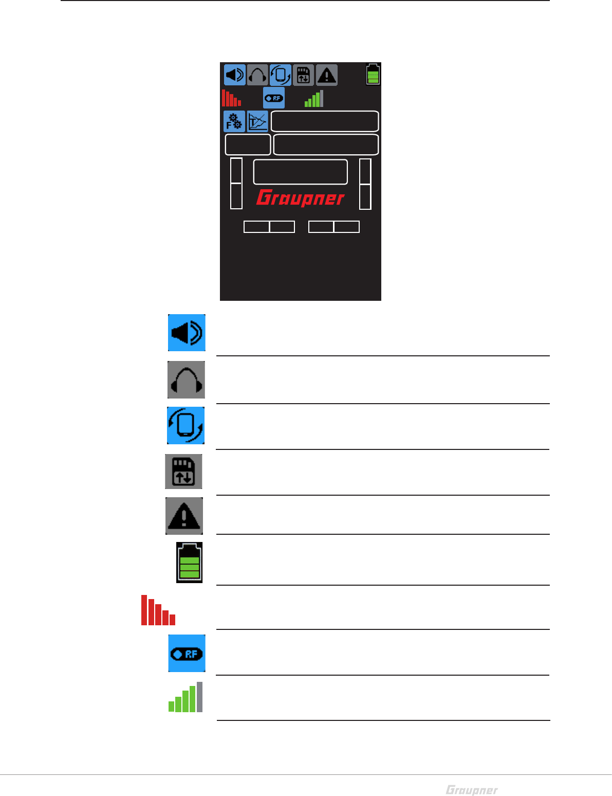
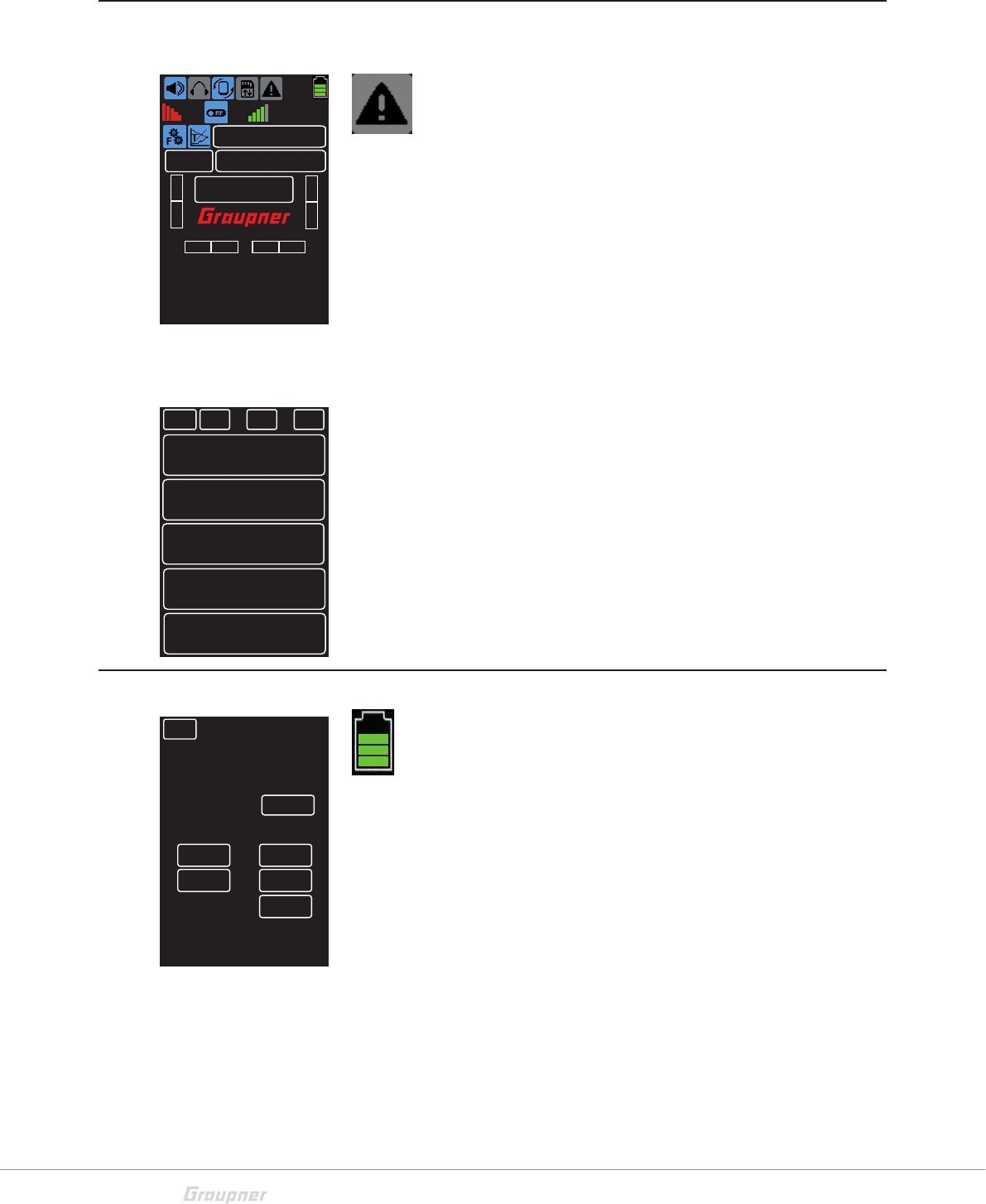
Start display
Symbol explination
TX
3.9V
4.8V
RX
RX
000:00.0
ST TH
ST TRIM TH TRIM0%
100%
0%
0%
CH3 CH4
BK D/R
ST D/R
PS1
+100% 100%
PS2OFF OFF
M - 1 MODEL 1
NORMAL
O.TIME 0 : 23 : 02 B.TIME 0 : 11 : 59
CH3 CH4
1
Voice output (announce)
Blue = Active / Gray = Inactive
Earphones (announce)
Blue = Connected / Gray = Disconnected
Display rotation (function - press)
Normal = 1 / 90° right = 2 / 90° left = 3
SD card (indicator)
Blue = Inserted / Gray = Not Inserted
Display warnings (function - press)
Warnings display (see chapter “Warnings”)
Transmitter battery display (function - press)
Graphic representation of battery power level and green voltage information
(see chapter “Voltage indicator calibration”). Blinks while battery charging.
Reception strength (display)
Red bars representing receiver (RX) field strength.
RF switched on (display)
Blue = RF On / Gray = RF Off
Transmission strength (display)
Green bars representing transmitter (TX) field strength
Receiver (RX) input voltage.
RX
TX
RX 4.8V
3.9 V
20 / 48 S1008_X-8E_jh_V1
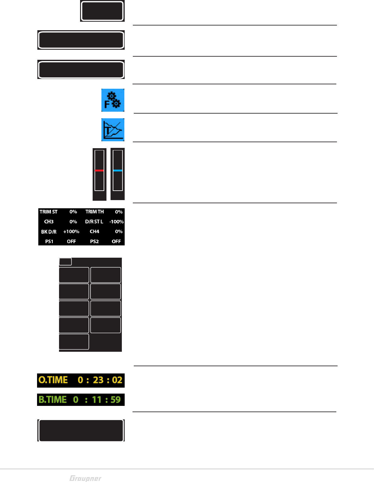
Backdfgsd
M-1
Tap for model memory selection
Model 1
Tap to input the model name
Profile
Tap to switching between the five profiles.
Main menu
Tap to move to main menu
Telemetry menu
Tap to move to telemetry menu
Bar display (display only)
Steering
Throttle
Percent display / status display
Shows the position percentage of steering, throttle, dual-rate
and the switch state of PS1 and PS2.
Tap this display screen to access a detail screen for more infor-
mation. (Display only.)
Model use time (see chapter “Timer”).
Battery use time (see chapter “Timer”).
Laps timer: Tapping opens the “Timer” menu.
M - 1
MODEL 1
NORMAL
TRIM ST
BACK NORMAL
0%
TRIM TH
0%
PS1
OFF
CH3
0% -100%
D/R ST L
PS2
OFF
PS3
OFF
BK D/R
+100%
CH4
0%
000:00.0
TH ST
BACK
21 / 48
S1008_X-8E_jh_V1
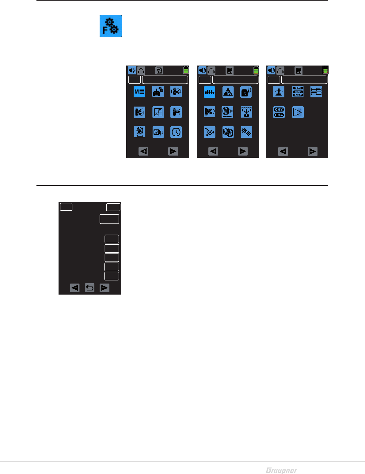
Main Menu
Push the “F” icon in the main display to access the menu. The
menu system is comprised of 3 pages. Scroll between the
pages by tapping the <+ and -> directional buttons at the bot-
tom of the screen. Tap the blue icons to access the related sub-
menu screen.
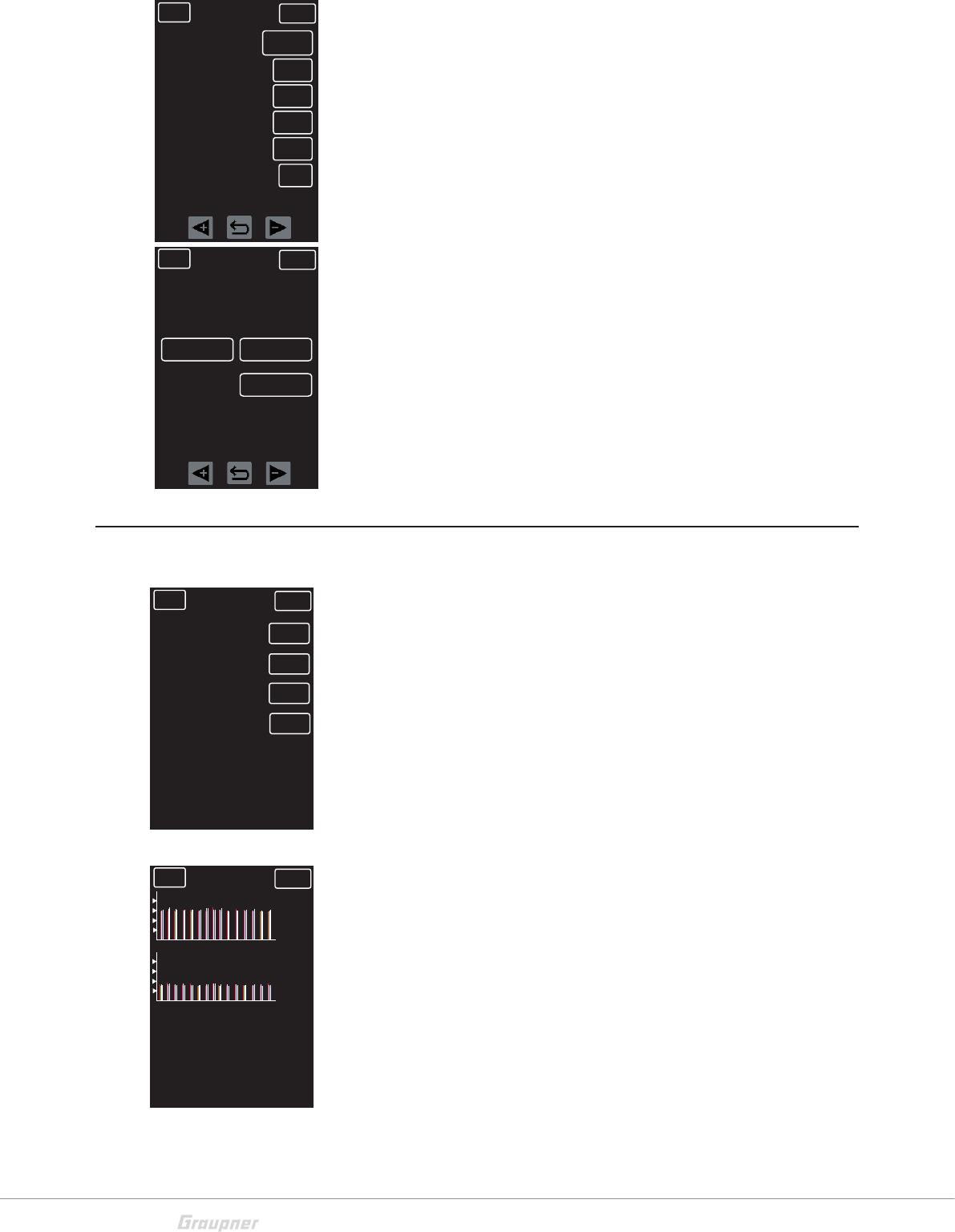
H/W SET
The H/W SET menu controls system setup and display settings.
To switch between System and Display tap the button to the
right of H/W TYPE.
System settings (H/W TYPE = SYSTEM)
Battery type - This transmitter only works with a LiPo battery.
LiPo - The warning threshold is automatically set to 3.6V.
Battery warning - The battery warning threshold can be manually
adjusted by 0.1V incriments.
Startup tone - Turn ON or OFF the startup melody.
Voice volume - Speaker volume control for voice announce-
ments. OFF = no sound / 05 = highest volume.
Power saving - Turns ON or OFF a power-saving mode that
begins a 1 minute countdown following a period of inactivity.
After the countdown the transmitter will automatically switch off.
Secret Mode - Refer to the Secret Mode chapter for additional
information on these settings.
3.9V
MODEL 1BACK
SW SET S/MODE SERVO
AUX TELE.
3.9V
MODEL 1BACK
M-SEL RF SET REVERSE
TRA ADJ DR/EXP TRIM
B.R.A. IDLE UP TIMER
3.9V
MODEL 1BACK
PROFILE REVERSE
P/MIX
S/SPEED START
A.B.S
B-MIX
TH RESP
H/W SET
BACK NORMAL SERVO
Batt type LI-PO
3.4 V
Batt Warning
Startup tone
Voice volume
Power saving
ON
03
OFF
H/W Type SYSTEM
Secret Mode SET
22 / 48 S1008_X-8E_jh_V1
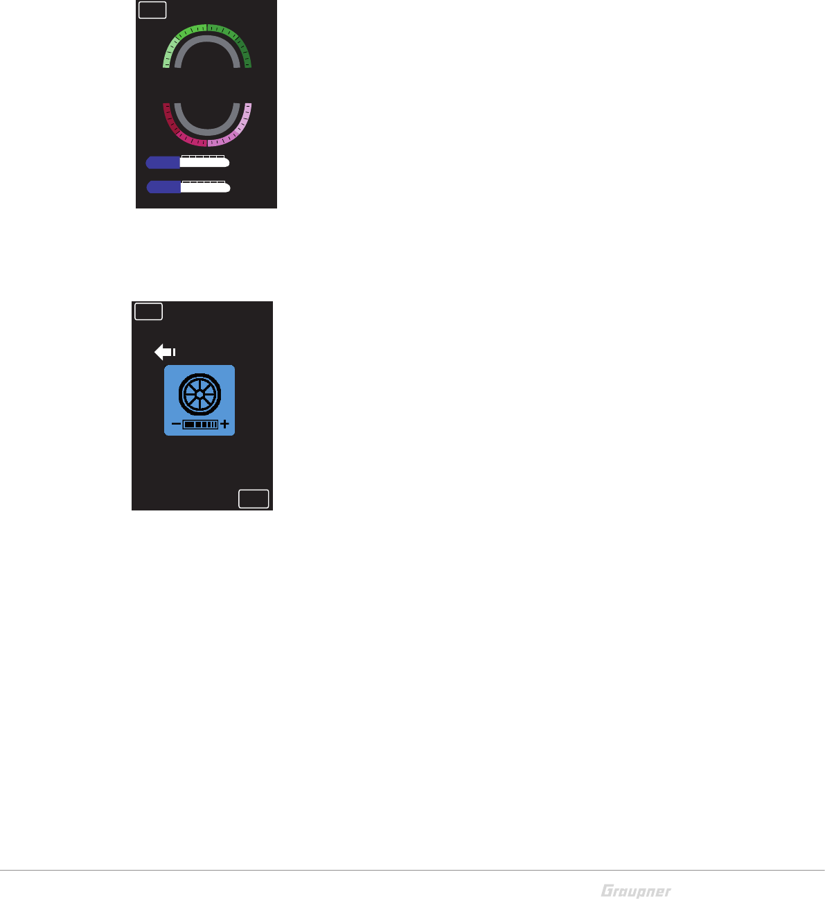
Display settings (H/W TYPE = DISPLAY)
Brightness - Adjust brightness level from 1 - 20
Display light - Switching the backlight ON or OFF.
Touch sense - Adjust the touch screen sensitivity.
1 = very sensitive / 5 = reduced sensitivity.
LED control - Opens a separate page in where users can switch
on/off the transmitter's LED lights or change their colors.
Display mode - Change the display orientation.
1 = Normal. 2 = 90° right rotation. 3 = 90° left rotation.
RFID - Displays transmitter's identification number.
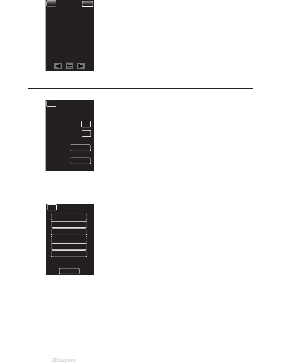
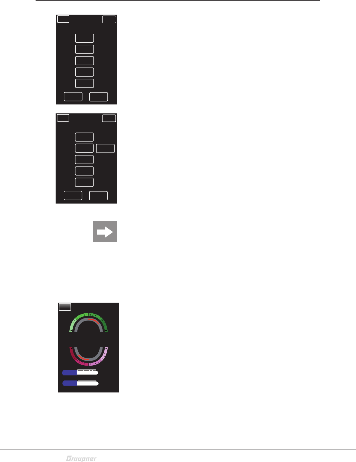
TELE. (Telemetry Menu)
Setting & Data View
This menu option allows setup of receiver's telemetry menu.
Refer to the receiver's user's manual for specific telemetry setup
information.
RF Status View
This display displays the frequency band and channel assign-
ments.
BACK NORMAL SERVO
Brightness 15
OFF
Back light
Touch sense
LED control
Display mode
1
SET
1
H/W TYPE Display
RFID 55555
BACK NORMAL SERVO
LEFT
OFF
RIGHT
FRONT
BLUE
RED
BACK NORMAL SERVO
SETTING & DATA VIEW >>
RF STATUS VIEW
VOICE TRIGGER
DEVICE MANAGEMENT
>>
>>
>>
BACK NORMAL SERVO
QUA
TD
ERR
Vc
96% 100%STR
- 56 dB
1 2 3 4 5 6 7 8 9 10 11 12 13 14 15
1 2 3 4 5 6 7 8 9 10 11 12 13 14 15
RD - 36 dB
9ms
4.9 4.9
Vm

23 / 48
S1008_X-8E_jh_V1
Voice Trigger
Only connected sensors and receivers are active.
REPEAT: If the REPEAT function is activated (via SW/FUN
menu, VOICE RPT button), set the repetition frequency of the
voice output here.
TRIGGER: Switch ON or OFF voice output from play list.
FIXED VOICE: Tap to open a drop-down menu of all voice
announcemnts available on the SUMD-V2 system.
Device Management
If the SUMD-V2 system's channels are set in the RF SET menu
at "CH FUNCTION", this menu manages the administration of
all devices connected to the receiver. (display only)
Device List
This menu shows a list of all connected devices and to which
receiver port they are connected. Devices can be assigned to
channels here.
New Device
Plug in a new device and push FIND. A pop-up menu will appear
showing the device is being located and assigned to a device
list number. Once found, tap OK.
Repeat this process for each new device to be assigned to the
list.
BACK NORMAL SERVO
REPEAT 10s
--
OFF
OFFTRIGGER
FIXED VOICE
TRANSMITTER
PLAY LIST
CAR ESC
GENERAL
VARIO
RECEIVER
SERVO
AIR ESC
ELECTRIC
GPS
BACK NORMAL SERVO
Device List
LIST
New Device
Live Log Device
FIND
>>
BACK NORMAL SERVO
No
00 -
01
02
03
04
05
Device CH PORT
RECEIVER -
BACK NORMAL SERVO
Device List
LIST
New Device
Live Log Device
FIND
>>
FINDING
NO. 00
OK
24 / 48 S1008_X-8E_jh_V1
Live Log Device
If the device is equipped with the Bluetooth module S8351, real-
time telemetry data can be logged and analyzed and transmit-
ted via features available found in the Firmware Upgrade Studio.
This menu logs, lists and numbers all devices being tracked
through this option.
Refer to the Secret Settings chapter for additional information
on setting up this option.
Secret Mode
The "Secret mode" option is the last item on the "H/W SET"
menu.
Announcements (Voice Update)
By default, all voice announcements are recorded in German
and are saved in a voice packet that is stored in the transmitter's
internal memory. They can be replaced by a voice packet of a
different language at any time.
On the micro SD card (included) choose from the following lan-
guage options: German, English, French, Dutch, Italian and
Spanish.
You can also download additional language packets at
www.graupner.de.
Language change
Language change step by step:
1. Insert the included SD memory card in its slot.
2. Use the left switch to turn the transmitter on in RF mode.
3. Select the "Secret mode" menu in the H/W SET menu.
4. Tap the "Voice Update" button.
5. Highlight the language from the list by tapping the appropri-
ate button.
6. Tap the "Load" button. The selected language packet will be
stored in the transmitter memory.
7. The loading process is finished as soon as the progress bar
at the lower edge of the display disappears.
8. When this process is finished, switch the transmitter OFF.
BACK NORMAL SERVO
01
02
03
04
05
Device Number
BACK Secret Mode
>>
Voice Update
Stick Calibration >>
Interface USB PORT
BT Speed NORMAL
BACK Voice File List
Voice2_German
01
Voice2_English
02
Voice2_France
03
Voice2_Italiano
04
Voice2_Spain
05
Voice2_Dutch
06
Load
25 / 48
S1008_X-8E_jh_V1
Steering wheel and throttle lever calibration
If the center position of steering wheel or if the throttle lever does
not neutralize to 0%control travel, you can check and correct it
as follows.
Stick calibration step by step:
1. Go to the "M-SEL" menu and tap on an open model
memory slot to select.
2. Move to the "SERVO" menu without changing any trim
settings or other program settings.
3. Center the steering wheel or the throttle lever by moving
the steering wheel and the throttle lever to the middle
position. If the throttle lever and the steering wheel are
correctly centered, the display should match the one
shown at left.
4. One at a time, move the steering wheel and throttle lever
as far as they will go in all directions without exerting force
at their position limits. The values should register between
-100% and +100%.
5. If the throttle lever or the steering wheel does not reach
the desired values, tap the "Stick Calibration" button in
the "Secret Mode" option in the "H/W SET" menu.
6. Follow the prompts on the screen by moving the steering
wheel and the throttle lever in the directions shown and
keep them still. Confirm the position by tapping on the
ENT button. Repeat this procedure for all of the indicated
positions. If you have correctly calibrated all positions, a
confirmation message will be displayed. Tap "OK" to save
the calibrations. Tapthe "BACK" button to quit the pro-
cess and return to the submenu "Stick Calibration".
Interface (BT SPEED)
Use this menu to assign transmitter ports for telemetry data
transmission.
DATA PORT
Plug in the external Bluetooth module S8351 to the DATA port
on the rear side of the transmitter. In the BT SPEED line, FAST
or NORMAL will automatically select depending on the trans-
mission speed of the counterpart device.
USB PORT
Plug in the supplied connection cable 7168 to the micro USB
port on the rear side of the transmitter to establish a connection
with a PC.
BACK NORMAL
ST
L150%
F150%
R150%
B150%
0%
0%
TH
0%
0%
0%
CH3
CH3
0%
BACK
0 %
LEFT
Stick Calibration
ENT
26 / 48 S1008_X-8E_jh_V1
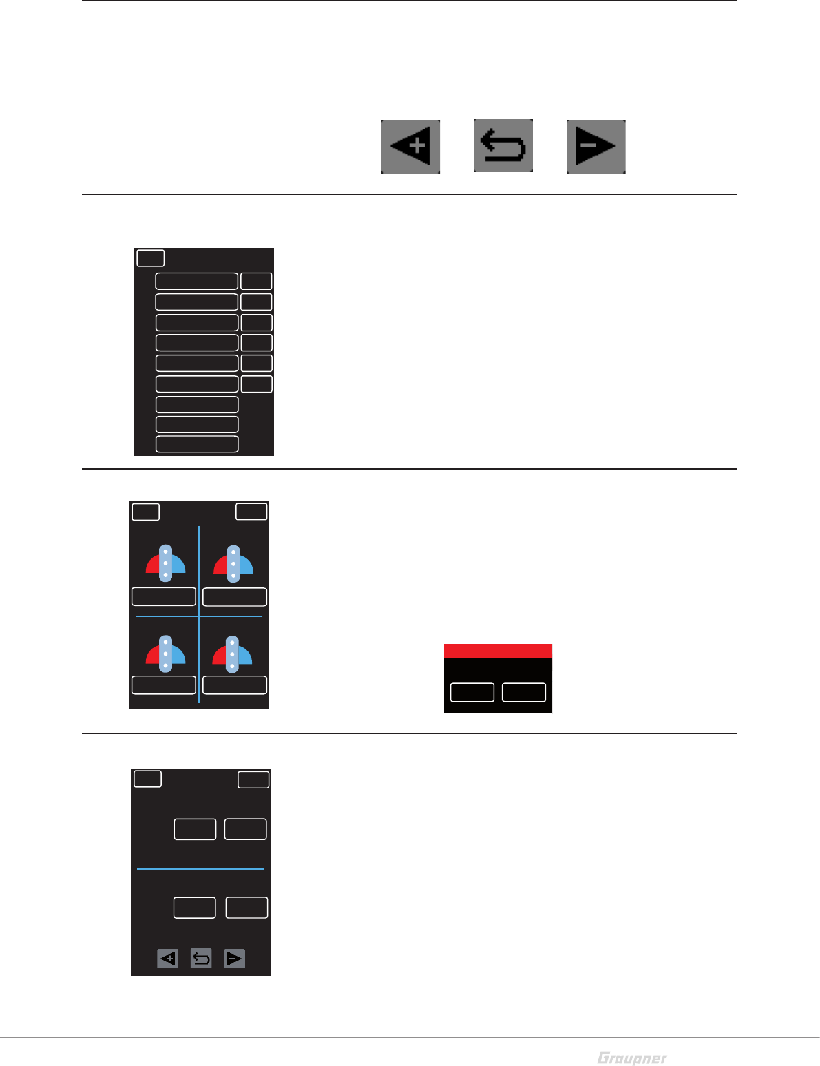
Display warnings
Tap the exclimation point symbol in the top line of the
Start Display to open the warnings display screen-
showing the current values for transmitter voltage (TX
VOLT), receiver voltage (RX VOLT), signal strength
(STRENGTH), speed controller current (ESC CUR.)
and speed controller voltage (ESC VOLT).
Acoustic (A-) and optical (S-) warnings can be activated or
deactivated by tapping the ON or OFF buttons.
Resets the alarms by tapping Clear (CLR).
Voltage display calibration
From the Main Menu, tap on the battery symbol to pull up
the voltage calibration display. Calibrate the voltage dis-
play as follows:
Voltage display calibration step by step:
1. Measure the battery voltage with a voltmeter.
2. Tap on the Cali. Data button.
3. Enter the data by changing the value by 2 or 10 unit
incriments.
4. To SAVE tap and confirm the safety query through
YES.
5. The new value is displayed under Tx Volt
TX
3.9V
4.8V
RX
RX
000:00.0
ST TH
ST TRIM TH TRIM0%
100%
0%
0%
CH3 CH4
BK D/R
ST D/R
PS1
+100% 100%
PS2OFF OFF
M - 1 MODEL 1
NORMAL
O.TIME 0 : 23 : 02 B.TIME 0 : 11 : 59
CH3 CH4
TX VOLT 3.9 V 0
RX VOLT 0.0 V 0
ESC VOLT 0.0V 0
ESC CUR. 0.0A 0
STRENGTH 0% 0
BACK CLR OFF ON
A- S-
BACK
+2
34814
+10
-2
-10
SAVE
3.95V
Tx Volt Cali. Data
NORMAL
27 / 48
S1008_X-8E_jh_V1
Change the values in an input field
The following three buttons are visable on the lower part of the
display of many of the following menus. To raise or lower a value
by pressing the <+ or -> buttons. Reset the default value
through the curved back-arrow button.
M-SEL (Model Selection)
Model settings can be managed and saved into memory slots
by choosing from the following options:
SEL - Change active model memories.
IMP.M - Import model memories from the SD card.
EXP.M - Export model memories to the SD card.
RES - Reset a model memory to the factory presets.
Warning: All personal settings will be deleted!
CPY - Copy the actual model memory in a new model mem-
ory.
REVERSE (Servo Reverse)
The servo operates in two directions:
Normal - Reverse
To change servo directions, tap the NORMAL/REVERSE but-
ton of the related servo to toggle between options. If changing
the throttle direction, a safety warning will appear. Tap YES or
NO to verify the selection and the change will take effect.
TRIM
This trim function allows for the entire servo travel to be moved,
i.e. full deflection position changes.
In the second line is displayed the respective trim value that has
been set through the buttons.
Tap on the related button. Change the values by pushing the <+
or -> keys. Press the curved arrow key to reset to the default
value (0%).
BACK
MODEL 1
01
02
03
04
05
06
07
NEXT
MODEL 2 SEL
MODEL 3 IMP.M
MODEL 7
MODEL 6 CPY
MODEL 5 RES
MODEL 4 EXP.M
08 MODEL 8
09 MODEL 9
BACK
NORMAL
NORMAL SERVO
NORMAL
NORMAL NORMAL
ST TH
CH3 CH4
BACK
NORMAL
NORMAL SERVO
NORMAL
NORMAL NORMAL
ST TH
CH3 CH4
Warning
Are you sure?
YES NO
BACK
0%
SV/TR
ST
NORMAL SERVO
TH
TX/TR
0%
0% 0%
CH 3 CH 4
0%
SV/TR
TX/TR
0%
0% 0%
28 / 48 S1008_X-8E_jh_V1
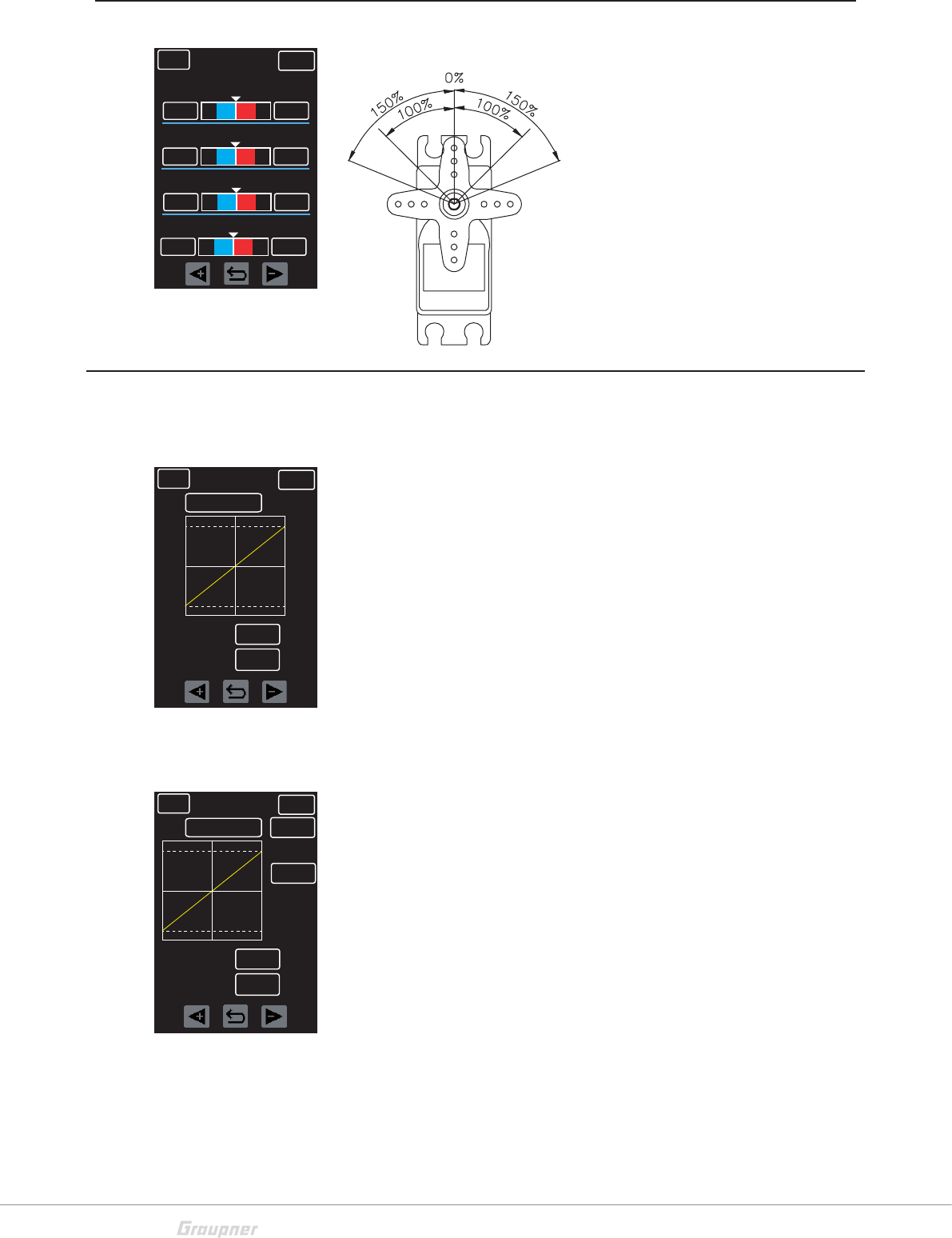
TRA ADJ (End Point Adjustment)
End Point Adjustment
This function sets the maximum
travel of the servo per channel.
The left and right deflection can be
set separately in the range from
0% - 150%. Press the related
button. Change the values by
pushing the <+ or -> keys. Press
the curved arrow key to reset to
the default value (100%).
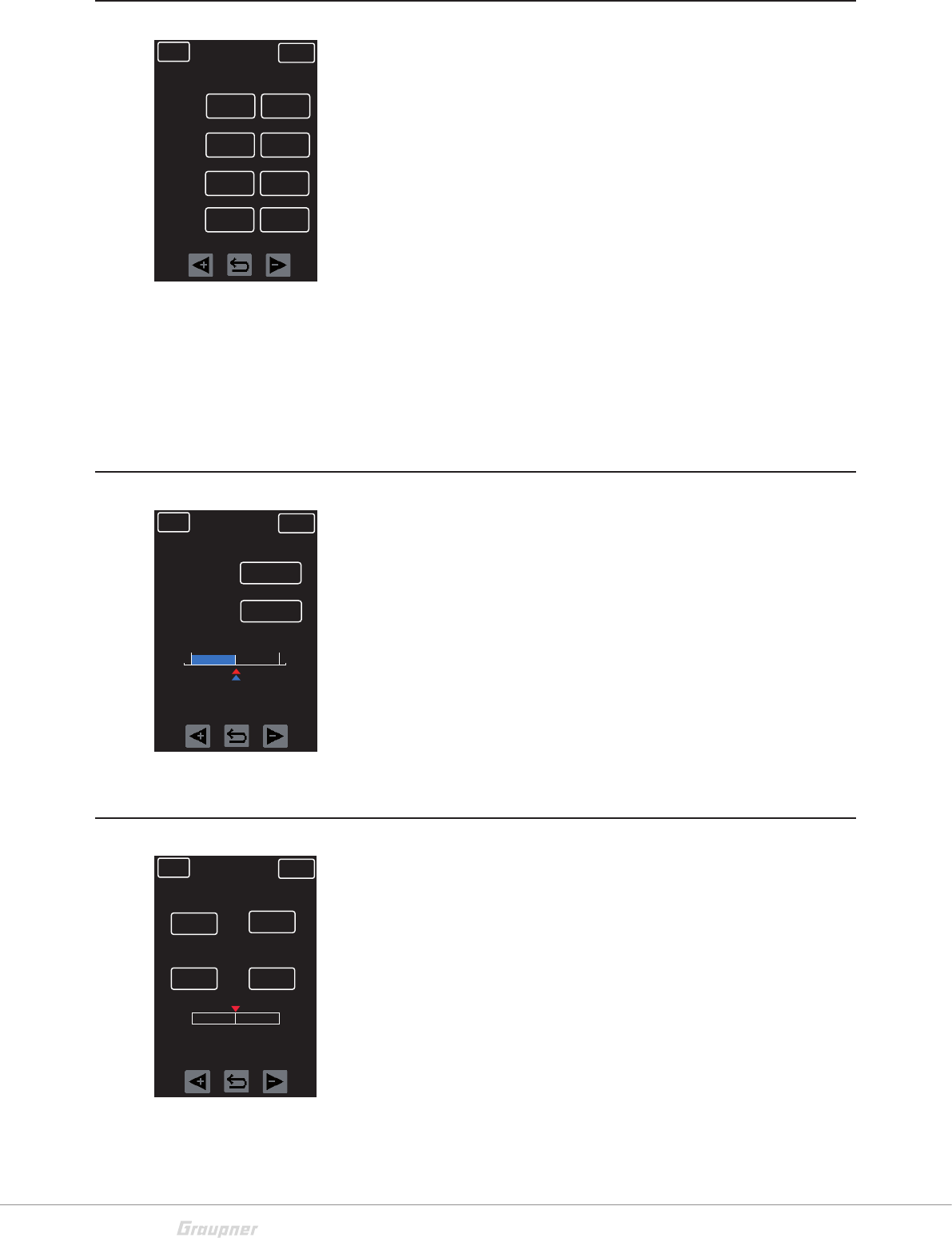
To set the DR (Dual Rate) and EXPO (Exponential) function for
the steering and throttle channel, press the STEERING or
THROTTLE button in the CH line. All setting changes are rep-
resented in the diagram.
Setting STEERING channel
D/R: 0% - 100% Limit the steering course. Press the <+ or ->
keys to raise or lower value. Press the curved arrow key to reset
to the default value (100%).
EXP: -100% to + 100% Exponentially change the steering
course. Press the <+ or -> keys to raise or lower value. Press
the curved arrow key to reset to the default value (0%).
Setting THROTTLE channel
D/R: 0% - 100% Limit the throttle course. Press the <+ or ->
keys to raise or lower value. Press the curved arrow key to reset
to the default value (100%).
EXP: -100% to + 100% Exponentially change the throttle
course. Press the <+ or -> keys to raise or lower value. Press
the curved arrow key to reset to the default value (0%).
FWD: Choose between forward and brake area. Refer to the
D/R and EXP settings described above and the FWD/BRK set-
tings described on the following page.
TYPE: Select between EXPO or throttle CURVE
CURVE: Refer to the setting instructions on the following page.
BACK
100%
LEFT
NORMAL SERVO
RIGHT
100%
ST
100%
BRK FW
100%
TH
100%
UP DN
100%
CH3
100%
UP DN
100%
CH4
BACK
STEERING
NORMAL SERVO
CH
100%
D/R
0%EXP
BACK
THROTTLE
NORMAL SERVO
CH
100%
D/R
0%EXP
FWD
TYPE
EXP
BACK
DR/EXP (Dual Rate/Exponential)
29 / 48
S1008_X-8E_jh_V1
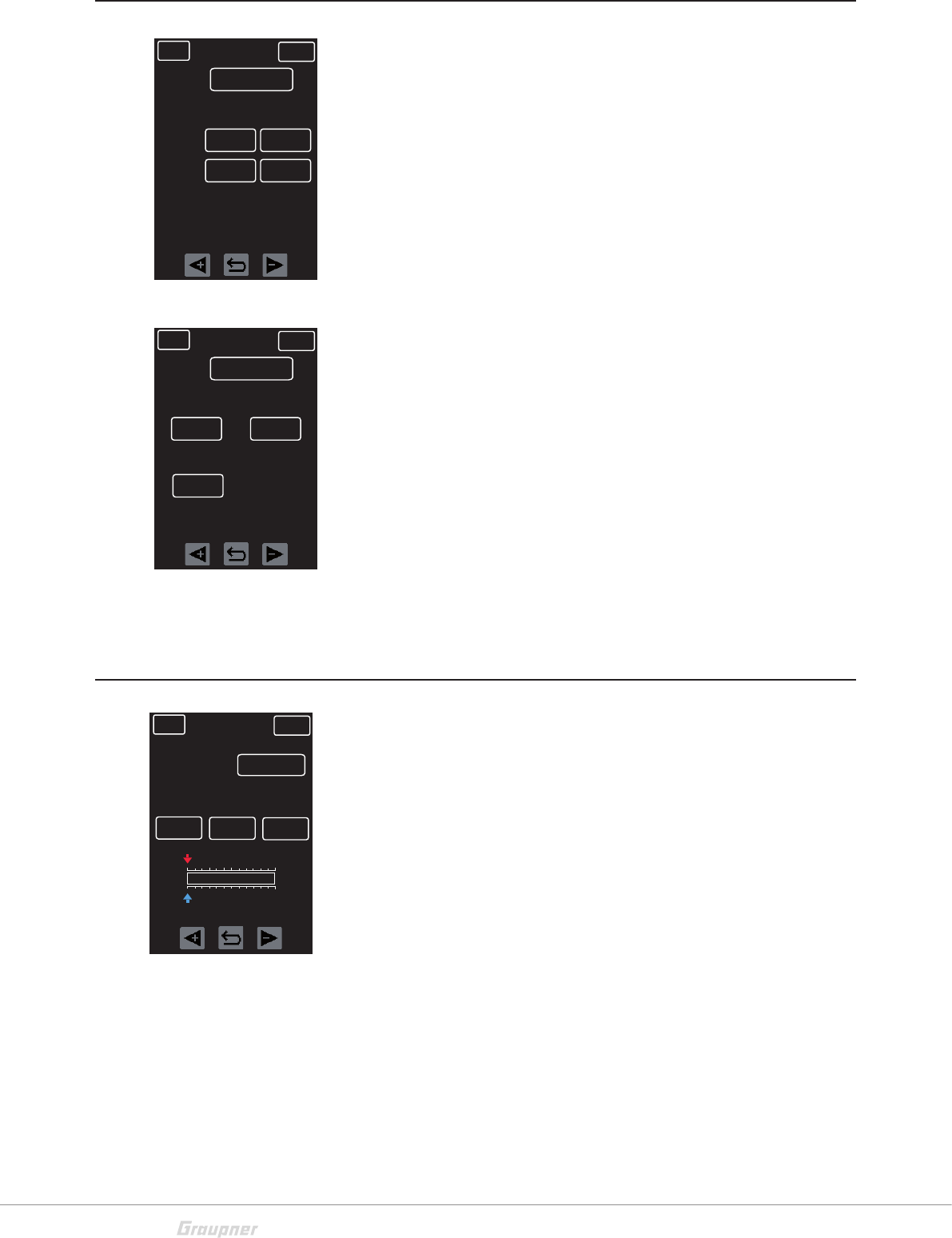
THROTTLE FWD point setting step by step:
1. Press the "ST OFF" button to switch to "ST ON".
2. Move the throttle lever.
3. A green line moves horizontally through the diagram.
4. Press the +/- key to create a new point. Multiple points
can be set by pressing the arrow key.
5. Delete highlighted points by pressing the +/- key.
THROTTLE FWD point moving step by step:
1. Press the "ST ON" button to switch to "ST OFF".
2. Press the <+ or -> keys to scroll through the points. Points
will highlight red when selected. Delete highlighted points
by pressing the +/- key.
3. Select the X-axis or the Y-axis button. Press the <+ or
-> keys to change axis curve or to reposition points along
the axis.
TH.hold
Use this option while programming a curve prevent the motor
from running. Tap the ON and OFF button to switch the throttle
channel on and off.
Brake force setting
1. Select the "THROTTLE" setting by pressing the "STEER-
ING" button.
2. Select the "BRK" setting by tipping on the "FWD" button.
3. Moving the throttle lever. The green axis line moves in the
diaplay.
4. To adjust the force setting, select the percent button near
"D/R" or "EXP". Press the <+ or -> keys to raise or lower
value. Press the curved arrow key to reset the default
value.
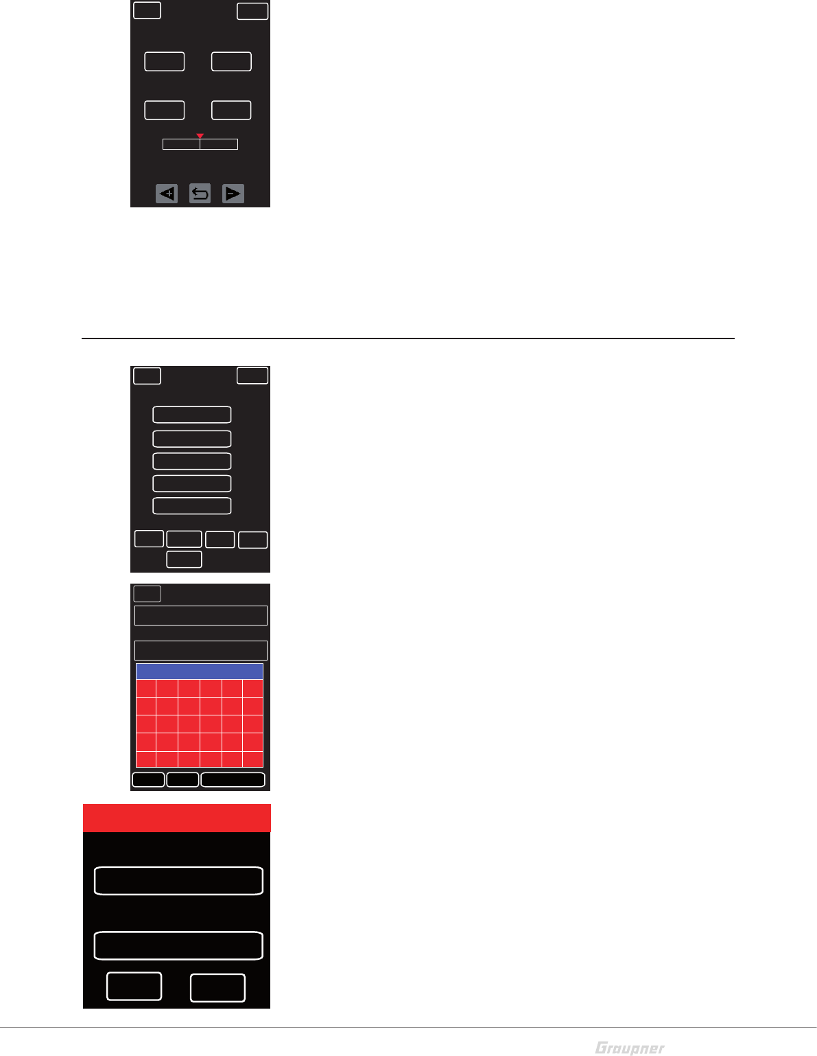
B.R.A. (ATL)
Break rate and travel setting menu.
RATE: Factory default setting is F50:B:50. Press the button in
the RATE line to switch to F70:B:30 and move the servo center.
B.R.A: To adjust the travel, highlight the percent button in the
B.R.A. line. Press the <+ or -> keys to raise or lower value.
Press the curved arrow key to reset to the default value (100%).
BACK
THROTTLE
NORMAL SERVO
X-axis
CH
ON
POINT ? 0%
TYPE
Curve
Y-axis
ST OFF
FWD
Curve
TH.hold
OFF
+/-
BACK
THROTTLE
NORMAL SERVO
CH
D/R +100%
BRK
EXP 0%
BACK NORMAL SERVO
RATE
100%
B.R.A
F50:B50
BK FW
0%
30 / 48 S1008_X-8E_jh_V1
B-MIX
Break mixer options menu, including mixer channel assignment,
mixer rate setting, delay time and ABS activation.
ACT: To activate the break secure function, press to change
INH (inhibit/off) to ON.
RATE: To set the break mixer part, press the percent button
on the RATE line. Press the <+ or -> keys to raise or lower value.
Press the curved arrow key to reset to the default value (100%).
DELAY: To set a delay time prior to activating the ABS, press
the percent button on the DELAY line. Press the <+ or -> keys
to raise or lower value. Press the curved arrow key to reset to
the default value (0.00s).
ABS: To activate the ABS function, press to change INH
(inhibit/off) to ON.
TH RESP (Throttle Response)
Throttle response settings menu. The throttle and break travel
can be adjusted in one percent incriments, causing the servo to
automatically jump to the set value during operation. This setting
can compensate backlash of the throttle linkage or throttle
response weakness in lower ranges.
FW: 0% - 100% To set the throttle, press the percent button
on the RATE line. Press the <+ or -> keys to raise or lower value.
Press the curved arrow key to reset to the default value (0%).
BK: 0% - 100% To set the break, press the percent button
on the RATE line. Press the <+ or -> keys to raise or lower value.
Press the curved arrow key to reset to the default value (0%).
IDLE UP (Pumping)
Motor start function settings menu. Holds the throttle to a spe-
cific value to enable a better start for cold combustion
engines.
POS: To adjust throttle position, press the percent button on
under POS. Press the <+ or -> keys to raise or lower value.
Press the curved arrow key to reset to the default value (0%).
NOTE: After starting the engine, this function must be deactivated;
the throttle lever has no effect during the IDLE UP function.
CTL: Assign this function to a switch. Refer to the SW SET
chapter for additional information on how to program switches.
BACK
INH
CH 3
NORMAL SERVO
CH 4
ACT
RATE
DELAY
ABS
INH
+100% +100%
0.00s 0.00s
INH INH
BACK NORMAL SERVO
FW
0%
BK
BK FW
0%
0%
BACK NORMAL SERVO
POS
NONE
ACT
SET
CTL
PUMPING
ON
0%
BK FW
31 / 48
S1008_X-8E_jh_V1
PUMPING
Automatic throttle activation menu. Set throttle strength and
delay time to protect motor during refueling.
POS: To set the strength of the throttle activation, select the per-
cent button below POS. Press the <+ or -> keys to raise or
lower value. Press the curved arrow key to reset to the default
value (0%).
DELAY: To set delay time between throttle activations, select
the percent button below DELAY. Press the <+ or -> keys to
raise or lower value. Press the curved arrow key to reset to the
default value (0.5s).
ACT: Press ON or INH (inhibit/off) to switch the activation func-
tion on or off.
CTL: Assign this function to a switch. Refer to the SW SET
chapter for additional information on how to program switches.
PROFILE
Set up to five different profiles for the model memories. Create
names and assign settings to a programmable switch. (Refer to
the SW SET chapter for additional information on assigning
switches.)
Settings that have been changed in the other menus will be
automatically populated in the assigned profile.
Change profile name:
1. Select profile to be renamed by highlighting any line, 1 - 5.
2. Press the NAM button at the bottom of the screen.
3. The current name appears in a field at the top of a new
screen. Use the red keypad to input a new name.
4. To save, press EN in the lower right side of the keyboard.
5. Press the BACK button to return to the main menu.
Copy profile:
1. Select the profile to copy by highlighting the profile name.
2. Press CPY. A pop-up window will appear.
3. To select the target profile, tap to scroll through the saved
profiles. Press YES to confirm selection.
Delete profile:
1. Select the profile to delete by highlighting the profile name.
2. Press DEL. Settings will reset to factory default values.
WARNING: profile will be deleted without confirm query!
BACK NORMAL SERVO
DELAY
NONE
ACT
0%
CTL
POS
INH
0,5s
BK TH
NONE
BACK
NORMAL
NORMAL SERVO
NEW NAM CPY
DEL
1
PROFIL 1
PROFIL 2
PROFIL 3
PROFIL 4
ACTPROFILE
2
3
4
5
CTL
BACK Current Profile Name
PHASE 1
A
New Profile Name
CAPS NUM SPECIAL
B C D E F
G H I J K L
M N O P Q R
STU V W X
Y Z CL SP DE EN
FROM NORMAL
TARGET
PROFIL 2
YES NO
COPY
32 / 48 S1008_X-8E_jh_V1
S/SPEED
Steering and throttle servo speed settings menu.
For the steering servo, you can set the speed for left and right
and for forward and return travel separately.
For the throttle servo, a point can be set at which the speed is
set in two steps.
STEERING
Highlight the field to be adjusted by pressing the appriporiate
button in the LEFT or RIGHT columns and TURN or RETURN
lines. Press the <+ or -> keys to raise or lower value. Press the
curved arrow key to reset to the default value (100).
THROTTLE
HIGH or NEUTRAL: Select the field to be adjusted by pressing
the appriporiate button. Press the <+ or -> keys to raise or
lower value. Press the curved arrow key to reset to the default
value (100).
POINT: To set the switchover point between both ranges, high-
light the button under POINT. Press the <+ or -> keys to raise
or lower value. Press the curved arrow key to reset to the default
value (50).
START
Automatic start function settings menu.
RATE: To allow a quick start without spinning the drive wheels
while the throttle is held on a specific value, press the percent
button below RATE. Press the <+ or -> keys to raise or lower
value. Press the curved arrow key to reset to the default value
(0%).
T/POS: To use this function, first assign a switch that sets the
START function to READY. When the throttle lever exceeds the
set trigger point, the READY (standby) mode is activated. To
adjust the trigger position, press the percent button below T/
POS. Press the <+ or -> keys to raise or lower value. Press the
curved arrow key to reset to the default value (0%).
TIME: To delay the response of this function when exceeding
the trigger point, select the button below TIME. Press the <+ or
-> keys to raise or lower value. Press the curved arrow key to
reset to the default value (0.0s).
BACK NORMAL SERVO
LEFT
STEERING
RIGHT
CH
100
TURN
RETURN
100
100 100
BACK NORMAL SERVO
HIGH
THROTTLE
CH
100
50
100
NEUTRAL
POINT
BACK NORMAL SERVO
RATE
START
0%
OFF
T/POS TIME
0% 0.0s
33 / 48
S1008_X-8E_jh_V1
TIMER
Timer and date settings menu. To toggle between the Timer
and Date display, press the NEXT button at the top of the
screen.
TIMER Display
P.ALARM: To set the time for a pre-alarm that will be active
before the main alarm, select the button in the P.ALARM line.
Press the <+ or -> keys to raise or lower value. Press the curved
arrow key to reset to the default value (00).
MODE: To toggle between mode options, press the button in
the MODE line. Choose UP for increasing count, DOWN for
countdown and LAP for lap timer. If LAP is selected, the START
SW function will automatically set to TH, allowing the timer to
start through the throttle lever.
START SW: This function is only available in UP or DOWN
mode. Pressing the button in the START SW line brings up the
SW SET menu. For additional information on these settings,
refer to the SW SET chapter.
LAP SW: To assign a start/stop function to the timer, press the
button in the LAP SW line. This brings up the SW SET menu.
For additional information on these settings, refer to the SW
SET chapter.
LAP List: To view total laps, best lap time and average lap time,
press the right-arrows button on the LAP List line to view the
statistics display. To reset to zero, press the CLR key.
LIST: The lap times list has 120 memory slots. To view a full
list of lap times, press the button at the top of the statistics
display. The best lap is alway marked in red and highlighted
with a B. Scroll through the list by pressing the << and >>
arrow keys at the bottom of the screen. Clear the list by
pressing the CLR key at the bottom of the screen.
Vibrator: To set or change alarm vibrations, press the button in
the Vibrator line. There are five different vibration options to
scroll through.
BACK NORMAL NEXT
00 sec
00 00
:
Vibrator
>>
SET TIMER
P.ALARM
MODE
UP
START SW
NONE
LAP SW
NONE
LAP List
00 00
:
NONE
TIME INFO
BACK NORMAL SERVO
TIMER
0 : 0 . 0
LIST
LAP
BEST LAP
0
AVERAGE LAP
0 : 0 . 0
CLR
BACK NORMAL SERVO
No
1
2
4 B
7
6
5
3
10
9
8
11
13
12
14
15
LAPTIME No LAPTIME
0 : 22.70
0 : 10.45
0 : 5. 9
0 : 0. 89
0 : 3. 94
16
17
19
22
21
20
18
25
24
23
26
28
27
29
30
<< CLR >>
34 / 48 S1008_X-8E_jh_V1
DATE/TIME
Date/Time and Battery/Model Time settings menu.
From the TIMER menu, press the NEXT button at the top of the
screen.
DATE/TIME
To set the date and time, press the SET button under the DATE
line. This unlocks the Year, Month, Day, Hour, Minute and Sec-
ond fields. Select to highlight and press the <+ or -> keys to
raise or lower value. To save and lock the fields, press SET
again.
BATTERY/MODEL TIME
To reset the battery or model times to zero, press the B.RES or
M.RES buttons.
SW SET
Control Key
Use this menu to assign functions to trim buttons, switches and
rotary controls. Some buttons and switches have default func-
tions assigned. All buttons, switches, controls and defaults can
be assigned as follows:
1. Press the Control Key arrow >> button to bring up the
Function screen.
2. Press the NEXT button to scroll through the screens.
3. Press the control button to select the desired function for
the control. Depending on the control there are different
functions available here. Assigned functions are greyed
out. (See list on the next page.)
4. Press the <+ or -> keys to select the function.
REV/NOR: To change between normal and reverse switch
function, press the button under REV to toggle between options.
T/S: To set the increase number for each click or step, press
the <+ or -> keys to raise or lower value. Press the curved arrow
key to reset to the default value (1). Only available on trims and
rotary controls.
Direct Button
To assign a menu shortcut function to buttons S1, S2 (under the
display):
1. Press the button on line 1 to set S1; line 2 to set S2.
2. Press the <+ or -> keys to scroll through display options.
3. To activate settings press the ON or OFF button on the
ACT line.
BACK NORMAL
DATE
1 : 19 : 33
/
SET
B.RES
2048 /
211
TIME
16 : :
20 27
BATTERY TIME
1 : 02 : 52 M.RES
MODEL TIME
NEXT
BACK NORMAL SERVO
Control Key
Direct Button
Menu Screen
>>
>>
>>
BACK NORMAL SERVO
FUNC
ST TRIM
SW
TR1
TR2
TR3
TR4
REV T/S
NEXT
TH TRIM
CH3
ST D/R
NOR
NOR
NOR
NOR
1
1
1
1
BACK NORMAL SERVO
TELE.
No Display
1.
2. SERVO
ACT ON
35 / 48
S1008_X-8E_jh_V1
Menu Screen
The green marked area represent the first main menu page, the
yellow marked area indicates the second main menu page, the
blue marked area indicates the third main menu page (see Main
Menu section)
RES: Press the button at the top of the screen to return all func-
tions to default factory presets. A warning screen will pop-up to
verify this option. Press YES or NO to continue.
Change the display assignation:
1. Press on the field to be changed. The function name will
apper on the button in the upper left corner of the screen.
2. Available buttons for this field will appear crossed out in
green.
3. Select the desired function button. Confirm change by
pressing the button in the upper left corner of the display
screen.
4. To delete or unselect, tap the BLANK button in the upper
right corner of the display screen.
BACK RES
M-SEL REVERSE SUB-TRIM
EPA DR/EXP B. R. A
B-MIX TH RESP IDLE UP
Q.LINK TIMER S-VIEW
H/W SET TELE.
S/SPEED RF SET START
A.B.S S/W SET FAIL SAFE
P/MIX AUX S/MODE
M-SEL REVERSE SUB-TRIM
EPA DR/EXP B. R. A
B-MIX TH RESP IDLE UP
Q.LINK TIMER S-VIEW
H/W SET TELE.
S/SPEED RF SET START
A.B.S S/W SET FAIL SAFE
P/MIX AUX S/MODE
BLANK
M-SEL
BACK NEXT
D/R ST L D/R ST P1
D/R ST P3
D/R ST H
TRIM ST
D/R TH P3
D/R TH H BK D/R
TRIM CH4
S-TRIM C3
BX CH3 RT
NORMAL
D/R ST P4
D/R TH P1
D/R TH P4
TRIM TH
S-TRIM ST
S-TRIM C4
BX CH4 RT
D/R ST P2
D/R ST P5
D/R TH P2
D/R TH P5
BK EXP
TRIM CH3
S-TRIM TH
ATL
G/B TH
BACK NEXT
G/B BS IDLE UP
SPD ST RT
NORMAL
PUMPING
SPD ST LT SPD ST RR
SPD ST LR SPD TH HO SPD TH NT
SPD C3 RT SPD C3 LT SPD C3 RR
SPD C3 LR SPD C4 HO SPD C4 NT
START T/P START RT ABS T/P
ABS MOV C3 C4
FR MIX 1 A FR MIX 1 B FR MIX 1 X
FR MIX 1 Y FR MIX 2 A FR MIX 2 B
BACK NEXT
NORMAL
P-MIX 2 X P-MIX 2 Y P-MIX 3 L
P-MIX3 P1 P-MIX3 P2 P-MIX3 P3
P-MIX3 P4 P-MIX3 P5 P-MIX3 H
P-MIX4 L P-MIX4 P1 P-MIX4 P2
P-MIX4 P3 P-MIX4 P4 P-MIX4 P5
P-MIX4 H P-MIX5 L P-MIX5 P1
P-MIX5 P2 P-MIX5 P3 P-MIX5 P4
P-MIX5 P5 P-MIX6 H CL SPD RT
CL SPD RT ST>> C3 C3 >> ST
BACK NORMAL
START ABS CH2 ABS CH 3/4
IDLE UP PUMPING CH3
CH4 CW MODE ESC MODE
TK MODE VOICE RPT VOICE TRG
FIX.VOICE T1 START T1 RESET
T1 LAP T2 START T2 RESET
T2 LAP Q.LINK
Select 1 to 3 for TR 1 - 5 / DV
Select for PS 1 + 3 Select for PS 2
BACK NORMAL
START ABS CH 2 ABS CH3/4
IDLE UP PUMPING CH3
CH4 CW MODE ESC MODE
TK MODE VOICE RPT VOICE TRG
FIX.VOICE
36 / 48 S1008_X-8E_jh_V1
FAIL SAFE
Fail Safe settings menu. In case of receiver signal loss or inter-
ruption, assign the servo channel to a predefined position. For
example, set an engine-powered model to idle (or an elec-
tric-powered model to shut off), so the model does not move
uncontrollablly.
FREE: Channel is empty with no failsafe assigned.
HOLD: Holds the servo in the previous position.
F/S: The servo automatically moves to a defined position
To set the position: Press and change the channel line button
to F/S. A percent value button will appear to the right in the POS
column. Press the percent button to select and set servo posi-
tion by moving the related control. Press the SET button to con-
firm. The POS button displays the assigned position of the
servo. Press the STO button to save all settings before exiting.
DELAY: To set the delay time between signal loss and failsafe
launch, press the button on the DELAY line to choose between:
50ms, 100ms, 250ms, 500ms, 750ms and 1.0s. Press the
STO button to save all settings before exiting.
Attention
To store settings, press the STO button on the bottom of the
screen before exiting this menu. Settings will not be saved until
the STO button is pressed and the "Position stored" confirma-
tion message appears.
SERVO (S View)
Servo monitor (display only).
This display shows the servo travels of all four control channels.
Access this display by pressing the Servo icon in the main menu,
or by pressing the Servo button in the upper right corner of most
submenu displays.
BACK NORMAL SERVO
ST
MODE POS
TH
CH3
CH4
DELAY
FREE
STO SET
FREE
FREE
FREE
100ms
BACK NORMAL SERVO
ST
MODE POS
TH
CH3
CH4
DELAY
HOLD
STO SET
F/S
FREE
FREE
100ms
0%
BACK NORMAL
ST
L150%
F150%
R150%
B150%
+100%
+100%
TH
0%
0%
0%
CH3
CH3
0%
37 / 48
S1008_X-8E_jh_V1
BACK NORMAL SERVO
MST CH3
SLV
>>
ST
TH
ST
CH3 CH4
CLR
Img.1
Img.2
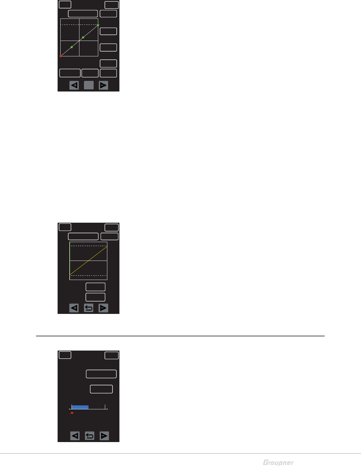
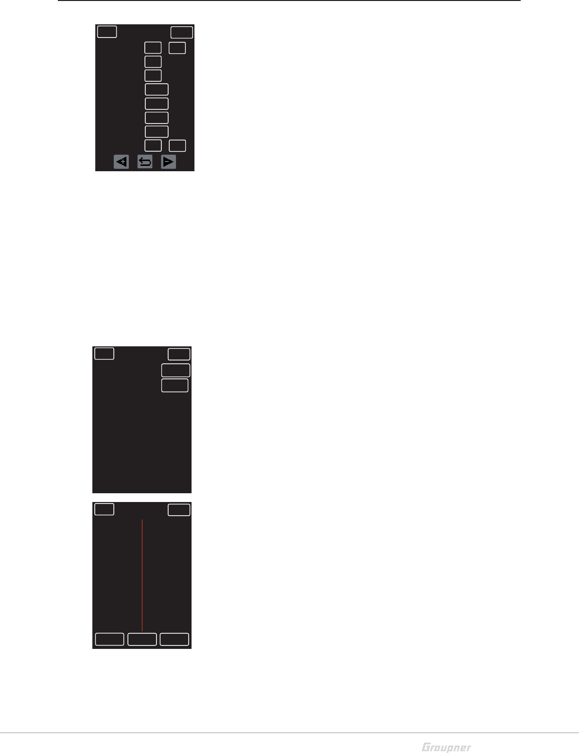
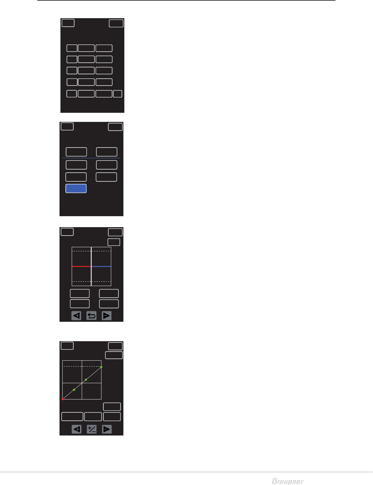
P/MIX
Mixer setup menu. Assign linear mixers to line numbers 1 and
2; curves mixers to line numbers 3 through 5. Activate mixers
by pressing the first button in the number line to change from
INH (inhibit/off) to ON.
Pressing the buttons in the MST or SLV columns will open a
new display screen. To assign the origin (MST/master) and the
target (SLV/slave), highlight the appropriate button above the
blue line and select the applicable channel button below. To
clear the selection press the CLR button.
Return to the P/MIX menu screen by pressing the BACK button.
An arrow >> button will appear in the SET column.
Press the arrow >> button for the linear and curve settings
menu. The Linear menu is only accessable on lines 1 and 2;
the Curve menu is only accessable on lines 3 through 5.
Linear menu (Img.1)
Select the "A" percent button to set the left (red) line and
the "B" percent button to set the right (blue) line. Use the
<+ or -> keys or press the curved arrow key to reset to
the default value (0%).
Press the "X" or "Y" percent buttons to move the line on
the X or Y axis via the <+ or -> keys. Press the curved
arrow key to reset to the default value (0%).
Move the throttle lever or the steering wheel. The green
line moves horizontally through the diagram.
Curve menu (Img.2)
Point setting step by step:
1. Press the button "ST OFF" to switch to "ST ON".
2. Move the throttle lever or the steering wheel. A green line
moves horizontally through the diagram.
3. Press the +/- key to set a new point. To delete, press the
point to highlight it red and press the +/- key.
4. Set up to a maximum of 5 points.
Point moving step by step:
1. Press the button "ST OFF" to switch to "ST ON".
2. Select the point to be reallocated by moving the steering
wheel or the throttle lever until the point is highlighted red.
3. Select the X-axis or the Y-axis button. Reposition the
point using +/- key.
4. The mixer is not linear and follows the set curve.
BACK NORMAL SERVO
ACT
INH
1.
MST SLV SET
2.
3.
4.
5.
INH
INH
INH
ON
NONE
NONE
NONE
NONE
ST
NONE
NONE
NONE
NONE
CH4 >>
BACK NORMAL SERVO
ST >> CH3 ACT
0%A
INH
B
X Y
0%
0%
0%
BACK
ACT
NORMAL SERVO
X-axis
ST>> CH3
T-OFF
POINT ? 0%
IN
Y-axis
ST ON
INH
-100%
OUT
-62%
38 / 48 S1008_X-8E_jh_V1
AUX
Additional channel settings menu. Set the servo deflections to
OFF (center) and UP/DN on two additional control channels
(CH3 and CH4).
OFF: To set the central point, press the <+ or -> keys to raise
or lower value. Press the curved arrow key to reset to the default
value (0%).
UP: To set the upper end point, press the <+ or -> keys to raise
or lower value. Press the curved arrow key to reset to the default
value (0%).
DN: To set the lower end point, press the <+ or -> keys to raise
or lower value. Press the curved arrow key to reset to the default
value (0%).
S/MODE
Various model type setup menu. Preprogrammed mixers tuned
to the characteristics of model types crawler, track vehicle and
boat.
To activate the model function, press the INH (inhibit/off) button
to change to ON. An arrow >> button appears in the SET col-
umn.
Press the arrow >> button to bring up a settings menu specific
to the vehicle type.
CRAWLER
4WS: To use all wheel steering activation on Channels 1 and 3,
press INH (inhibit/off) button to change to ON.
DUAL ESC: To use two independent drive motors with 2 speed
controllers on channel 2 and 4, press INH (inhibit/off) button to
change to ON.
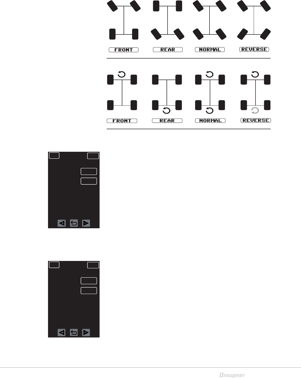
ST MODE: To adjust active 4WS steering, press to select the
button in the ST MODE line. Scroll between options by press-
ing the <+ or -> keys. Press the curved arrow key to reset to the
default (FRONT). (see image on next page).
ESC MODE: To adjust active DUAL ESC in 2 motors, press to
select the button in the ESC MODE line. Scroll between options
by pressing the <+ or -> keys. Press the curved arrow key to
reset to the default (FRONT). (See image on next page.)
SPD RATE: To set the maximum speed for both speed con-
trollers in DUAL ESC mode, press to select the percent button
in the SPD RATE line. Press the <+ or -> keys to raise or lower
value. Press the curved arrow key to reset to the default value
(0%). (See image on next page.)
BACK NORMAL SERVO
CH3
0%
CH4
OFF
UP
DN
0%
+100% +100%
+100% +100%
BACK NORMAL SERVO
ACT
INH
SET
CRAW
TANK
BOAT
INH
INH
BACK NORMAL SERVO
S/MODE
INH
4WS
CRAW
DUAL ESC
ST MODE
ESC MODE
SPD RATE
INH
NORMAL
NORMAL
0%
39 / 48
S1008_X-8E_jh_V1
ST MODE (steering)
ESC MODE (2 drives)
TANK
Use the ST MODE to mix the throttle and the steering on a
tracked vehicle and emit on Channel 1 and 2. Actuate steering
by adjusting SPD RATE of the left and right tracks speed.
ST MODE: Select the button to highlight and press to choose
between: TYPE 1 = standing rotation only, TYPE 2 = driving
rotation only. Press the curved arrow key to reset to the default
(TYPE1).
SPD RATE: To set the maximum speed of the drive, highlight
the percent button in the SPD RATE line and press the <+ or ->
keys to increase or decrease value. Press the curved arrow key
to reset to the default (100%).
BOAT
Use these mixers to actuate a second drive (ESC).
ST -> 3CH: To adjust the mixing rate from steering to Channel
3, press the <+ or -> keys to increase or decrease value. Press
the curved arrow key to reset to the default (0%).
3CH -> ST: To adjust the mixing rate from Channel 3 to steer-
ing, press the <+ or -> keys to increase or decrease value. Press
the curved arrow key to reset to the default (0%).
BACK NORMAL SERVO
S/MODE
TYPE1
ST MODE
TANK
SPD RATE 0%
BACK NORMAL SERVO
S/MODE
ST >> CH3
BOAT
CH3 >> ST 0%
0%
40 / 48 S1008_X-8E_jh_V1
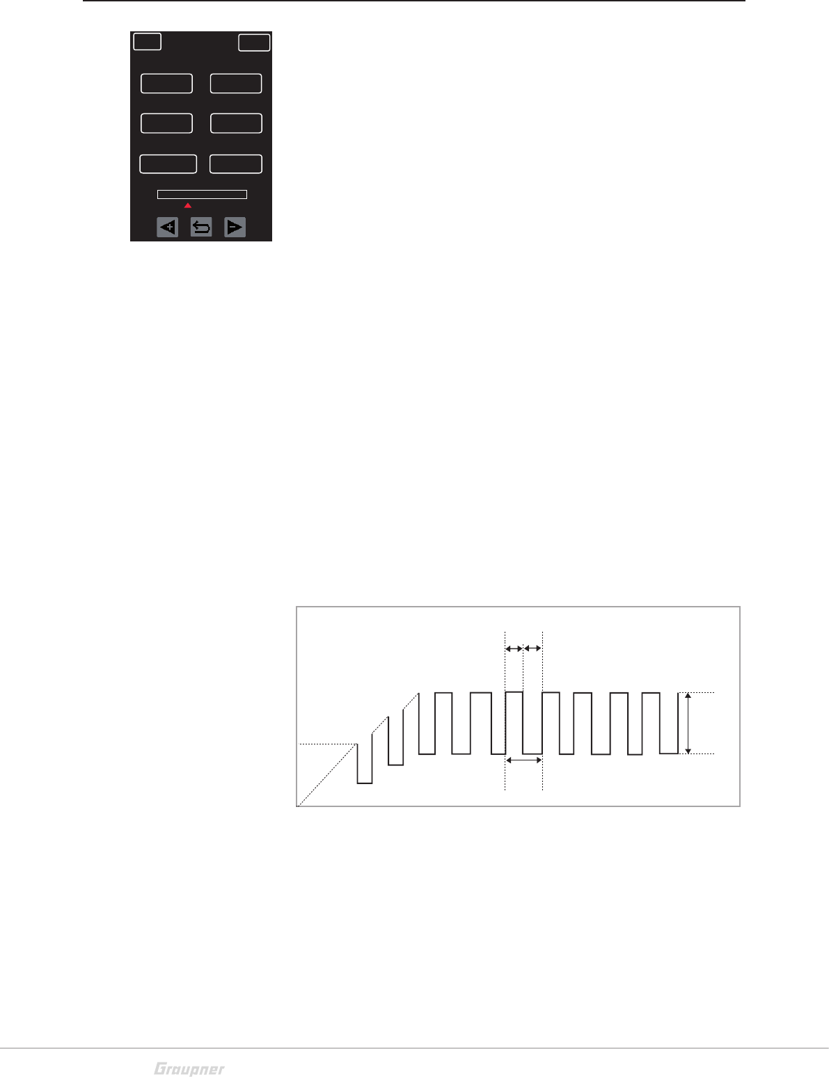
A.B.S
A.B.S setup menu.
A.B.S. enables a better braking response, since the brake is
actuated in pulses.
ACT: Press the button under ACT to choose between INH
(inhibit/off) and ON.
DUTY: To set the atio between pulse and pulse pause (see
image below), press the <+ or -> keys to raise or lower value.
Press the curved arrow key to reset to the default value (0).
T/POS: To set the point on the brake lever path from which the
A.B.S. will become active, press the <+ or -> keys to raise or
lower value. Press the curved arrow key to reset to the default
value (30%).
MOV: To set the pulse height (see image below), press the <+
or -> keys to raise or lower value. Press the curved arrow key to
reset to the default value (50%).
CYC: To set the pulse length (see image below), press the <+
or -> keys to raise or lower value. Press the curved arrow key to
reset to the default value (240ms).
DELAY: To set the delay time of the A.B.S. response (0 - 1 s),
press the <+ or -> keys to raise or lower value. Press the curved
arrow key to reset to the default value (0.00s).
BACK NORMAL SERVO
ACT
INH DUTY
T/POS MOV
CYC DELAY
0
30% 50%
120ms 0.00s
DUTY
CYC
MOVE
41 / 48
S1008_X-8E_jh_V1
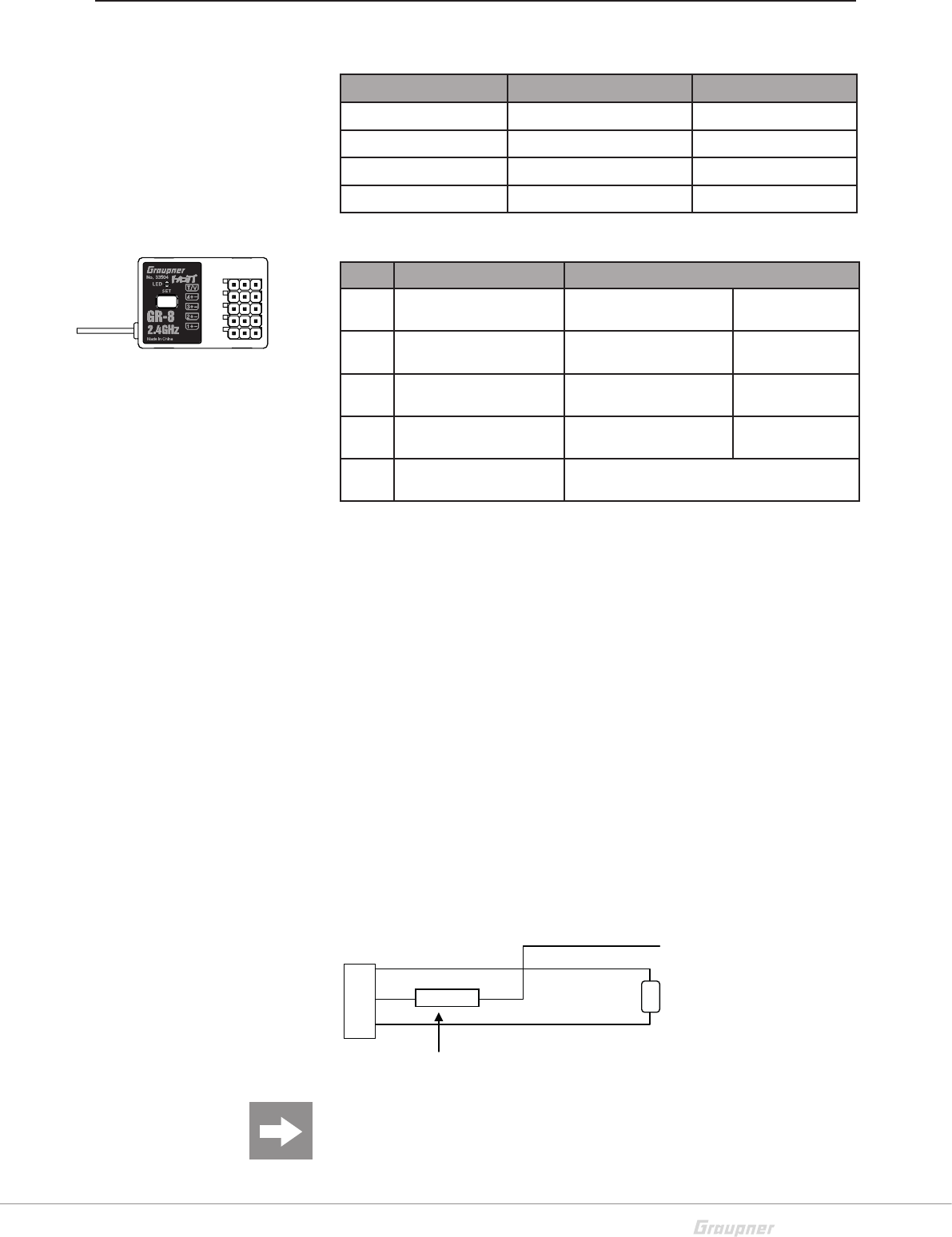
Operating receiver GR-8
Description LED indicator
Red LED Green LED
Not bound Flashing Off
Bound Off On
Error Flashing On
Binding Flashing Flashing
Channels function
Function Alternative
CH 1 Channel 1 signal
output SUMD-V2 BUS system Battery plug
connection
CH 2 Channel 2 signal
output SUMD-V2 BUS system Battery plug
connection
CH 3 Channel 3 signal
output SUMD-V2 BUS system Battery plug
connection
CH 4 Channel 4 signal
output SUMD-V2 BUS system Battery plug
connection
T/V Ext. temp./voltage
sensor ------
The power source for the receiver is connected through channel
1 to 4. If all of the channels are used, use a Y-cable on one chan-
nel.
CH 1+2: Connected the steering servo.
Channel 2: Connected with the throttle servo of engine-pow-
ered models or with the speed controller of electric-powered
models.
CH 3+4: Open channels freely assignable for special control
functions.
T/V socket:
Used to connecting the optional external voltage and tempera-
ture sensor S8362. When reaching the warning thresholds, an
alarm is generated (set the warning thresholds via Telemetry
menu). Sensor and voltage of a battery must only be connected
according to the following scheme:
ATTENTION: The receiver will be destroyed if you connect a bat-
tery directly to this socket without a pre-resistance. This socket
is not suited for the power supply of the receiver.
T
V
G
G
10K/C
NTC Temperatur-
Sensor
Ext.Spannung(+
)
(1 - 25,5V)
<CH3
<CH2
<CH1
<CH4
<T/V
42 / 48 S1008_X-8E_jh_V1
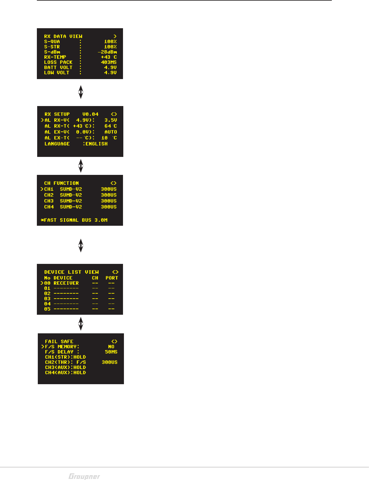
GR-8 Receiver Telemetry Menu
Display screen (display only)
S-QUA: transmission quality
S-STR: transmission power
S-dBm: transmission power in dBm
RX-TEMP: receiver temperature
LOSS PACK: lost data packets in milliseconds
BATT VOLT: receiver voltage
LOW VOLT: warning threshold for minimum receiver voltage
Warning Thresholds and Telemetry Language Setting Screen
AL RX-V: receiver voltage warning threshold
AL RX-T: receiver temperature warning threshold
AL EX-V: ext. voltage sensor warning threshold
AL EX-T: ext. temperature sensor warning threshold
LANGUAGE: language setting (telemetry menu only)
The current value is shown in brackets
Channel Properties Setting Screen (refer to RF SET section)
Settings:
USR1m50 - ULTRA SIGNAL 1.5msec
FSR3m00 - FAST SIGNAL 3.0msec
SUMD-V2 - FAST SIGNAL BUS 3.0msec
NSR6m00 - NORMAL SIGNAL 6.0msec
NSR12m0 - NORMAL SIGNAL 12.0msec
NSR24m0 - NORMAL SIGNAL 24.0msec
Connected Components Display (display only)
(Refer to Telemetry Menu section)
Fail Safe Setting Screen
F/S MEMORY: To save the data in the receiver, select "YES.
Press ENTER to confirm.
F/S DELAY: Fail Safe delay time
CH1(STR): FREE, HOLD, POSITION
CH2(TH): FREE, HOLD, POSITION
CH3(AUX): FREE, HOLD, POSITION
CH4(AUX): FREE, HOLD, POSITION
(Refer to Fail Safe section)

43 / 48
S1008_X-8E_jh_V1
Firmware Update - Transmitter
NOTE
In case of transmitter firmware update, carefully observe the follow-
ing instructions. Before every update it is recommend all model data
on the SD card be saved externally (refer to M-SEL section).
UPDATE USING THE BACK-SIDE USB SOCKET
Use a PC or laptop with the Windows XP, Vista, 7 or 8 OS.
Download an up-to-date software package from the Internet at
www.graupner.de and unpack it onto a PC or laptop. Connect
your switched-off transmitter with the PC or laptop by using the
USB cable (USB-A to mini-B-USB, 5 pole), which is supplied as
a standard accessory. Plug one end of the USB cable directly
into the 5 pole micro-USB port at the rear side of the transmitter
and the other end into a free USB port of the computer. For
more information, please refer to the update instructions PDF file
located in the respective software package.
44 / 48 S1008_X-8E_jh_V1
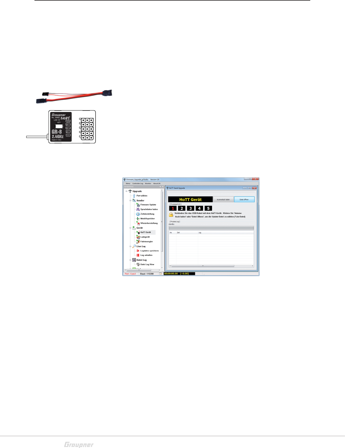
Firmware Update - Receiver
Updates to the receiver’s firmware are made via the telemetry
socket using a PC running Windows XP, Vista or 7 with the
included USB interface (order No. 7168.6), and adapter lead,
(order No. 7168.6A or 7168.S).
The programs and files required can be found in the Download
area for the corresponding products at:
www.graupner.de.
Connect the adapter lead to the USB interface. The connectors
are reverse polarity protected: note the small chamfers on the
sides. Never use force – the connectors should engage easily.
Connect the adapter lead to the receiver's socket 3 (CH 3). The
connectors are reverse polarity protected: note the small cham-
fers on the sides. Never use force – the connectors should
engage easily.
Update process
Ensure that the adapter lead is plugged into the receiver. Start
the Firmware Update Studio.
Select the correct COM-Port "Silicon Labs CP210x USB to
UART Bridge" under "Port Select" to which the USB cable is
connected.
To download the file, go to the menu and select the item: "HoTT
device". In the pop-up window, press the "Auto Download"
button. Once the firmware file is displayed, start the update by
pressing the "File Download" button.
If the file has been previously downloaded, go to the menu and
select the item: "HoTT device". In the pop-up window, press
the "File Download" button and select the previously-down-
loaded firmware file with the *.bin extension. Once the firmware
file is displayed, start the update by double-clicking on the file.
<CH3

45 / 48
S1008_X-8E_jh_V1
Battery Disposal
Disposal notes
This symbol on the product, user manual or packaging indicates
that this product must not be disposed of with other
household waste. It must be disposed of or recycled at a facil-
ity that accepts electrical and electronic equipment.
Materials are recyclable as marked. You are making an import-
ant contribution to environmental protection by recycling mate-
rials for reuse.
Batteries and accumulators must be removed from the device
and disposed of or recycled at a proper disposal centers. Con-
tact local authorities for the appropriate facility in your area.
Care and Maintenance
Notes on care
The product does not need any special maintenance. Always
protect it against dust, dirt and moisture.
Warranty
Graupner USA OPENHOBBY LLC at 3941 Park Drive Suite 20-571,
El Dorado Hills, CA 95762 warranties this product from the date
of purchase for a period of 24 months. The warranty applies only
to the material or operational defects already existing when you
purchased the item. Damage due to wear, overloading, incor-
rect accessories or improper handling are excluded from the
warranty. The legal rights and claims are not affected by this
warranty. Please check defects before making a claim or send
the product. If the item is found to be free of defects, we may
charge shipping and handling fees.
The present construction or user manual is for informational pur-
poses only and may be changed without prior notice. The most
current version can be found at www.graupnerusa.com on
the relevant product page. Graupner USA OPENHOBBY LLC assumes
no responsibility or liability for any errors or inaccuracies that
may appear in construction or operation manuals.
Graupner accepts no liability for printing errors.
P
IC warning
This device complies with Industry Canada licence-exempt RSS standard(s).
Operation is subject to the following two conditions:
(1) This device may not cause interference and (2) this device must accept any interference,
including interference that may cause undesired operation of the device.
Le présent appareil est conforme aux CNR d'Industrie Canada applicables aux appareils radio
exempts de licence.L'exploitation est autorisée aux deux conditions suivantes :
(1) l'appareil ne doit pas produire de brouillage, et
(2) l'utilisateur de l'appareil doit accepter tout brouillage radioélectrique subi, même si le brouillage
est susceptible d'en compromettre le fonctionnement.
Under Industry Canada regulations, this radio transmitter may only operate using an antenna of a
type and maximum (or lesser) gain approved for the transmitter by Industry Canada. To reduce
potential radio interference to other users, the antenna type and its gain should be so chosen that
the equivalent isotropically radiated power (e.i.r.p.) is not more than that necessary for successful
communication.
Conformément à la réglementation d'Industrie Canada, le présent émetteur radio peut
fonctionner avec une antenne d'un type et d'un gain maximal (ou inférieur) approuvé pour
l'émetteur par Industrie Canada. Dans le but de réduire les risques de brouillage
radioélectrique à l'intention des autres utilisateurs, il faut choisir le type d'antenne et son gain de
sorte que la puissance isotrope rayonnée équivalente (p.i.r.e.) ne dépasse pas l'intensité
nécessaire à l'établissement d'une communication satisfaisante.
This radio transmitter (identify the device by certification number, or model number if Category II)
has been approved by Industry Canada to operate with the antenna types listed below with the
maximum permissible gain and required antenna impedance for each antenna type indicated.
Antenna types not included in this list, having a gain greater than the maximum gain indicated for
that type, are strictly prohibited for use with this device.
Le présent émetteur radio (identifier le dispositif par son numéro de certification ou son
numéro de modèle s'il fait partie du matériel de catégorie I) a été approuvé par Industrie
Canada pour fonctionner avec les types d'antenne énumérés ci-dessous et ayant un gain
admissible maximal et l'impédance requise pour chaque type d'antenne. Les types d'antenne non
inclus dans cette liste, ou dont le gain est supérieur au gain maximal indiqué, sont strictement
interdits pour l'exploitation de l'émetteur.
FCC Warning
This device complies with Part 15 of the FCC Rules. Operation is subject to the following two
conditions
(1) this device may not cause harmful interference, and
(2) this device must accept any interference received, including interference that may cause
undesired operation. Changes or modifications not expressly approved by the party responsible
for compliance could void the user’s authority to operate the equipment.
Note 1: This equipment has been tested and found to comply with the limits for a Class B digital
device, pursuant to part 15 of the FCC Rules. These limits are designed to provide reasonable
protection against harmful interference in a residential installation. This equipment generates,
uses and can radiate radio frequency energy and, if not installed and used in accordance with the
instructions, may cause harmful interference to radio communications. However, there is no
guarantee that interference will not occur in a particular installation. If this equipment does
cause harmful interference to radio or television reception, which can be determined by turning
the equipment off and on, the user is encouraged to try to correct the interference by one or
more of the following measures:
—Reorient or relocate the receiving antenna.
—Increase the separation between the equipment and receiver.
—Connect the equipment into an outlet on a circuit different from that to which the receiver is
connected.
—Consult the dealer or an experienced radio/TV technician for help.
Note 2: 1.Changes or modifications to this unit not expressly approved by the party responsible
for compliance could void the user’s authority to operate the equipment.

46 / 48 S1008_X-8E_jh_V1
NOTES

47 / 48
S1008_X-8E_jh_V1
