GRAUPNER 16007100 2.4GHz Radio Controller User Manual S1033 mc 28 4D Teil 1 en indd
GRAUPNER CO., LTD. 2.4GHz Radio Controller S1033 mc 28 4D Teil 1 en indd
GRAUPNER >
15_MC-28 UserMan r1
EN
Manual
Copyright © Graupner/SJ GmbH
No. S1033
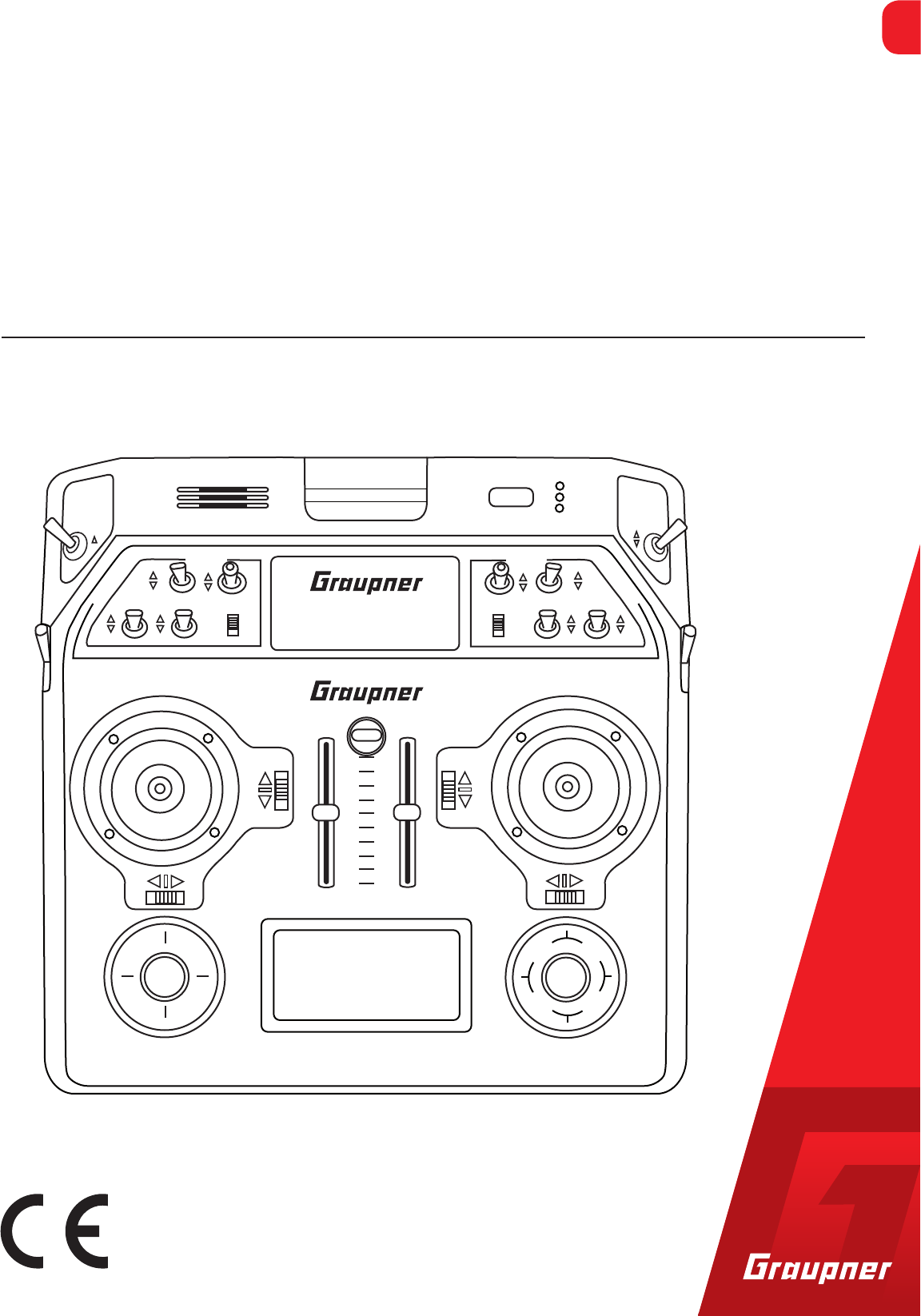
16 channel HoTT 2,4 GHz transmitter
mc-28 with 4D control sticks
Part 1
MC-28
MC-28
MC-28 MC-28
esc set
Manual


3 / 36
S1033_jh_V1_de
Index
Introduction ......................................................................... 5
Service Centre .................................................................... 5
Intended use ....................................................................... 6
Target group ....................................................................... 6
Package content ................................................................. 6
Technical Data .................................................................... 7
Symbols explication ........................................................... 7
Safety notes ........................................................................ 7
For your safety by handling the transmitter ......................... 8
For your safety by handling the battery ............................... 9
Description of the transmitter ......................................... 11
Control elements on the transmitter .................................. 11
Inside view ....................................................................... 13
Interfaces ......................................................................... 14
DSCsocket ...................................................................... 15
Memory cards .................................................................. 16
Display and touchpad ...................................................... 17
Symbols in the display ...................................................... 18
Key pad ........................................................................... 18
Commissioning ................................................................. 20
Hand pads ....................................................................... 20
Brackets for transmitter belt ............................................. 20
Anchorage for the transmitter belt .................................... 21
Opening/closing the transmitter housing .......................... 21
Switch the transmitter off .................................................. 23
Binding ............................................................................. 23
Charging the transmitter battery ....................................... 24
Low voltage warning ........................................................ 24
Battery use timer in the display ......................................... 24
Lithium battery ................................................................. 24
Use and menu functions .................................................. 25
Short-Cuts ....................................................................... 25
Hidden mode ................................................................... 27
Firmware update/Changing the display language ............. 28

Stick calibration ................................................................ 28
Telemetry data display ...................................................... 30
Firmware update ............................................................... 32
Update through memory card .......................................... 32
Update through USB port ................................................. 33
Problems during firmware update ..................................... 33
Declaration of conformity ................................................ 33
Notes on environmental protection ................................ 34
Care and maintenance ..................................................... 34
Warranty ............................................................................ 34
S1033_jh_V1_de
4 / 36
5 / 36
S1033_jh_V1_de
Introduction
Thank you very much for purchasing the Graupner mc-28 HoTT
transmitter.
Read this manual carefully to achieve the best results with your
transmitter and first of all to safely control your models. If you
experience any trouble during operation, take the instructions to
help or ask your dealer or Graupner Service Centre.
NOTICE
This manual is composed by two parts. Part 1 is contained in the
product's package content. Part 2 can be found in its last version on
www.graupner.de by the related item page.
Due to technical changes, the information may be changed in
this manual without prior notice. Keep updated by regularly
checking our own website, www.graupner.de to be always
updated with the products and firmware.
This product complies with national and European legal require-
ments.
To maintain this condition and to ensure safe operation, you must
read and follow this user manual and all the safety notes before using
the product!
NOTICE
This manual is part of that product. It contains important information
concerning operation and handling. Keep these instructions for future
reference and give it to third person in case you gave the product.
Service Centre
Graupner Central Service
Graupner/SJ GmbH
Henriettenstraße 96
D-73230 Kirchheim / Teck
Servicehotline
(+49) (0)7021/722-130
Monday - Thursday
9:15 am - 4:00 pm
Friday
9:15 am - 1:00 pm
Graupner USA
3941 Park Dr Suite 20-571
El Dorado Hills, CA 95762
Website: www.graupnerusa.com
Phone: +1 855-572-4746
Email: service@graupnerusa.com
Graupner in Internet For the service centers outside Germany please refer to our web
site www.graupner.de

S1033_jh_V1_de
6 / 36
Intended use
This remote-control system may only be used for the purpose
specified by the manufacturer for operation of remote control
models without passengers. Any other type of use is impermis-
sible and may damage the system and cause significant prop-
erty damage and/or personal injury. No warranty or liability is
therefore offered for any improper use not covered by these pro-
visions.
Read through this entire manual before you attempt to install or
use the transmitter.
Graupner/SJ constantly works on the development of all prod-
ucts; we reserve the right to change the item, its technology and
equipment.
Target group
The product is not a toy. It is not suitable for children under 14
years. The operation of the mc-28 HoTT transmitter must be per-
formed by experienced modelers. If you do not have sufficient
knowledge about dealing with radio-controlled models, please
contact an experienced modeler or a model club.
Package content
Transmitter mc-28 HoTT
Transmitter battery
Receiver (optional)
USB Adapter/Interface
USB cable
Micro SD card with adapter
Hand pads
Transmitter belt
Brackets for transmitter belt
Short and long stick-tops
Aluminum case
Transmitter manual (Part 1)
Receiver manual (optional)
The programming manual (manual part 2) can be found in its last
version on www.graupner.de by the related item page.
7 / 36
S1033_jh_V1_de
Technical Data
Transmitter mc-28 HoTT
Frequency band 2,4 … 2,4835 GHz
Modulation FHSS
Transmitting power 100 mW EIRP
Control functions 16 functions of which 4 can be trimmed
Temperature range -10 … +55 °C
Antenna Patch integrated in the case
Operating voltage 3,4 … 4,35V (1S LiPo)
Power consumption approx. 400 mA
Range approx. up to 4.000 m
Dimensions approx. 235 x 228 x 66 mm
Weight approx. 1250 g with transmitter battery
Note
The technical data of the optional receiver are available in the
manual included in the receiver package content.
Symbols explication
Always observe the information indicated by this warning sign.
Particularly those which are additionally marked with the CAU-
TION or WARNING. The signal word WARNING indicates the poten-
tial for serious injury, the signal word CAUTION indicates possibil-
ity of lighter injuries.
The signal word Note indicates potential malfunctions.
Attention indicates potential damages to objects.
Safety notes
These safety instructions are intended not only to protect the
product, but also for your own and other people’s safety. There-
fore please read this section very carefully before using the prod-
uct!
Do not carelessly leave the packaging material lying around,
since it might become a dangerous toy for children.
Persons, including children, with reduced physical, sensory
or mental capabilities, or lack of experience or knowledge,
or not capable to use safely the transmitter must not use the
transmitter without supervision or instruction by a responsi-
ble person.
!
!

8 / 36
Operation and use of radio-controlled models needs to be
learned! If you have never operated a model of this type
before, start carefully and make yourself familiar with the
model's reactions to the remote control commands. Pro-
ceed always responsibly.
Before you start using the remote control model, you have
to check the further relevant laws and regulations. These
laws you must obey in every case. Pay attention to the pos-
sibly different laws of the countries.
The insurance is mandatory for all kinds of model operation.
If you already have one, so please inform yourself if the oper-
ation of the respective model is covered by your insurance.
If this is not the case, conclude a special liability insurance
policy for models.
Protect all equipment from dust, dirt, moisture. All equip-
ment must be protected from vibration as well as excessive
heat or cold. The models may only be operated remotely in
normal outside temperatures such as from -10°C to +55°C.
First, always perform a range and function test on the ground
before you start using your model. Only so you can grant a
safe use! How to perform a range test is explained in the Part
2 of the manual.
Only operate all your HoTT components using the current
software version.
Start a data log every time you use your model. With a log-
data an occurred technical defect can be recognized and
verified. Only so it is possible to considerate an eventual
compliant.
For your safety by handling the transmitter
WARNING
Also while programming the transmitter, make sure that a con-
nected motor cannot accidentally start. Disconnect the fuel sup-
ply or drive battery beforehand.
Inform yourself before flying your
model on which maximum
altitude you can fly in the uncon-
trolled airspace over the starting
position and do not exceed it.
!
S1033_jh_V1_de
9 / 36
S1033_jh_V1_de
CAUTION
Risk of fire! Avoid every kind of short-circuit in all sockets of the
transmitter! Use only the suitable connectors. In no case the
electronic component of the transmitter may be changed or
modified. Due to licensing reasons, any reconstruction and/or
modification of the product is prohibited.
Note
During transport protect the model and the transmitter from
damages.
For your safety by handling the battery
CAUTION
Protect all equipment from dust, dirt, moisture. Only use in
dry locations.
Do not use any damaged battery. Risk of injury!
Any alterations to the battery can cause serious injury. Risk
of fire!
Batteries may not be heated, burned, short-circuited or
charged with excessive current or with reversed polarity.
While they are being charged, the batteries must be placed
on a non-flammable, heat-resistant and non-conductive sur-
face. Combustible or highly flammable objects are to be kept
away from the charging area. Batteries must be monitored
while they are being charged.
The maximum quick charging current specified for the
respective cell type may not be exceeded.
If the battery heats up above 60°C while it is being charged,
stop charging and let the battery cool down to approximately
30 - 40°C.
The batteries must not be modified. Do not directly solder or
weld the cells.
If handled improperly, there is a danger of fire, explosion, irri-
tation and burns. To extinguish a fire use: water, CO2, sand.
Leaked electrolyte is caustic and should not be touched or
come into contact with your eyes. In case of emergency,
rinse with a large quantity of water and consult a Med. Doc-
tor.
Always charge the battery fully.
!
!

10 / 36
The maximum charging current permitted may not be
exceeded.
Never leave the charger unattended when it is connected to
the power supply.
Batteries may only be charged in rooms fitted with smoke
detector.
Safety notes for stocking LiPo / LiIo batteries
Batteries may only be stored in non completely discharged
condition.
Batteries may only be stored in dry rooms with an ambient
temperature of +5°C to +25°C.
Stock the LiIo/LiPo batteries with a cell voltage of about
3,8V. If the cell voltage falls below 3 V, then the battery must
be necessarily charged. Deep discharge and storage in dis-
charge status (cell voltage < 3V) make the battery useless.
Charge and transport your batteries always in a safety bag.
S1033_jh_V1_de
11 / 36
S1033_jh_V1_de
Description of the transmitter
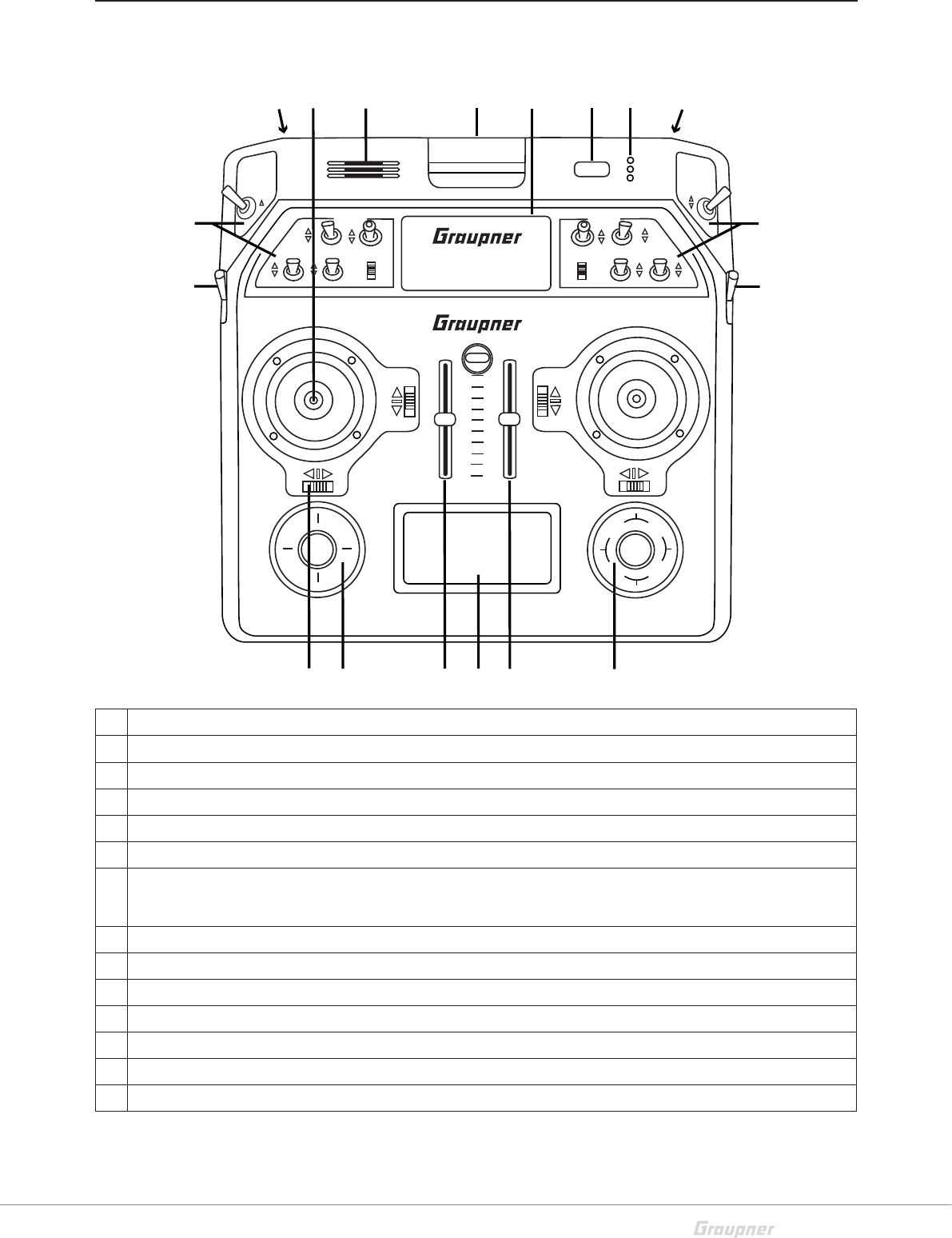
Control elements on the transmitter
1 Connection sockets (protected by a cover)
2 Control stick; left and right with 4D controls
3 Speaker
4 Antenna (integrated in the case)
5 ON/OFF switch
6 LED indicators (battery, RF radiation, warning signals, charge indicator)
7 Places for switches and buttons
As standard are installed: 12 switches with different designs, 2 INC/DEC buttons
8 Right rotary control "SD1"
9 Right touch pad with four-way keys
10 Slider controls "SR1" and "SR2"
11 LCD
12 Left touch pad with four-way keys
13 Digital trim
14 Left rotary control "SD2"
4
3
15 6
14
7
8
2
9
10
11
10
12
13
7
1
11
MC-28
MC-28
MC-28 MC-28
esc set
12 / 36 S1033_jh_V1_de
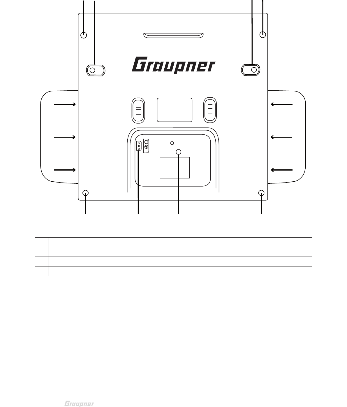
1 Five housing screws and six screws for the hand pads
2 SW16/PB18
3 SW17/PB19
4 Connection socket for transmitter battery (pay attention to the correct polarity)
11
1 1
1
1
1
1
1
1
23
14

13 / 36
S1033_jh_V1_de
Inside view
1 Sockets for optional transmitter controls and switches (connection sequence as preferred)
2 Lithium battery
3 RF module
4 Bluetooth module
5 SW17/PB19 (when transmitter is closed)
6 Transmitter battery plug
7 SW16/PB18 (when transmitter is closed)
43
1
7
2
5
6
14 / 36 S1033_jh_V1_de
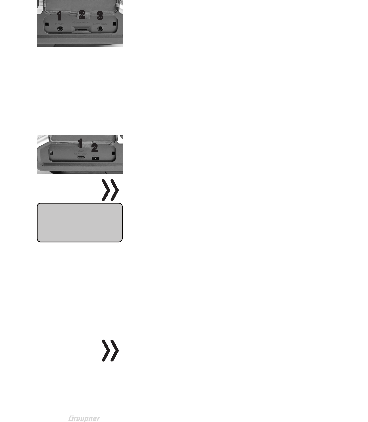
Interfaces
Provided connection
Left provided connections
1- DSC socket
On the left side is located the DSC socket. This socket allows
the trainer/pupil function and the use of flight simulators.
For more information on the DSC socket and the trainer/pupil
function see the section "DSC socket".
2- SD card slot
The card slot is suitable for micro SD memory card. For informa-
tion on removing and inserting the memory card, refer to the
section "memory cards".
3- Ear phones port
The ear phones port is suitable for a 3,5 mm jack. Though this
interface both acoustic signals and voice messages are emitted.
The volume can be controlled by "Voice volume" and "Signal vol-
ume" in the general settings.
Right provided connection
1- Micro USB port / battery charge and PC connection
Note
The micro USB socket is not suitable for flight simulator connection.
As soon as you connect the USB cable to the transmitter a
selection menu appears.. Here you can set up the function of
the micro USB port.
PC COM Port - for updates
Mass storage memory - to access to the SD card
Battery charge - only battery charging
Battery charging
Through the micro USB port you can charge the transmitter bat-
tery. Use the included USB cable to connect the transmitter to
a suitable USB port and charge the transmitter battery. If the
transmitter is switched on the charge time is longer than if the
transmitter is switched off.
The maximum charge current is 2 A.
Note
The full capacity is reached by the HV-LiPo batteries only if they
are externally charged with 4,35 V. The internal charging tension
is limited to 4,2 V for compatibility reasons.
More information are available in the section "Charging the trans-
mitter battery".
123
12
USB connected
PC COM Port
Mass storage
Charge only
15 / 36
S1033_jh_V1_de
PC COM Port connection
Through this socket it is also possible to connect the transmitter
to a PC. The software that the computer needs as well as the
appropriate USB driver can be found on the download page on
www.graupner.de for the respective product.
Mass storage memory
If you select this option, then you can accede from your PC
directly to the SD card (if insert).
2- Data socket
The data socket is suitable for connection of an optional smart
box or an external optional Bluetooth module.
DSCsocket
Connection socket for flight simulator or T/P systems
The standard two-pin DSC socket on the transmitter functions
as a TRAINER or PUPIL socket as well as an interface for flight
simulators or other external RF modules.
To ensure a correct DSC connection, observe the following:
Attention
When your transmitter is directly connected to a desktop computer
by a connecting cable (DSC cable) and/or a computer interface is
connected to your simulator, the transmitter may be destroyed
byelectrostatic discharge. This type of connection should therefore
only be used if you protect yourself from electrostatic discharge
while operating the simulator by wearing a commercially available
grounding armband. Graupner therefore strongly recommends only
using wireless simulators.
Perform any necessary adaptations in the menu.
When using the transmitter with a flight simulator or during the
teacher-pupil operation, leave the transmitter always OFF. Only
in this position even after connecting the DSC cable the RF
module of the transmitter remains inactive. Connect now the
DSC cable and switch the transmitter on.
The status LED is constantly red and in the display will appear
DSC.
In the upper display appears the transmitter logo.
The transmitter is now ready for use.
Note
If the transmitter is used as teacher transmitter it has to be switched
on before connecting the proper cable.
Connect the other end of the connecting cable to the device
while observing the relevant operating instructions.
PUPIL
#11
0:01h
S
F
«normal »
DSC
0:00.0
0:00.0
4.1V
0.0V
HoTT
16 / 36 S1033_jh_V1_de
Note
Make sure that all the plugs are securely inserted in the respective
sockets, and only use the provided plug-in connectionswith a 2-pin
jack plug on the DSC side.
In the "Transmitter setting" sub-menu, you can set one of the
following modes in the "DSC output" line depending on the
number of functions to be transmitted: PPM10, PPM16, PPM18
and PPM24. Default setting: PPM10.
Memory cards
Compatible memory cards:
micro SD up to 2 GB
micro SDHC up to 32 GB
Our recommendation: For a normal use a memory card with a
storage capacity of up to 4 GB is sufficient.
Inserting and removing the memory card step by step:
Switch off the transmitter.
The memory card slot is located in the left provided connections
of the transmitter.
To insert:
Push the SD card as deep as you need to win the spring resis-
tance of the slot. (contacts upward)
To remove:
Push the SD card slightly toward the card slot to unlock it and
then remove it.
The included memory card is ready for use as soon as the trans-
mitter is switched on. In the display appears the symbol of a
memory card.
Otherwise, folders are created on the memory card ( repre-
sented in the transmitter display by a permanent filling from left
to right memory card). When the animation finishes, the inserted
memory card is ready for use.
You can connect the memory card to your PC by using a mem-
ory card reader. Copy the data downloaded from the transmitter
page on the web site in the related folder of the memory card.
Insert the memory card in your transmitter.
Data recording/Data saving
The data recording in the SD card is linked to the log timer. If it
is started, the data recording starts as well and it stops when
the log timer is stopped.
GRAUBELE
#01
2:22h
S
F
«normal »
K78
0:00.0
0:00.0
5.5V
3.9V
M
HoTT

17 / 36
S1033_jh_V1_de
The data writing on the memory card is remarked by the symbol
of the "filling" of the memory card with black from left to right.
After the installation of the memory card, there is a folder struc-
ture in it. These folders are actually empty.
Finally, the log files are saved in sub-folders called "Modelname"
named according to the structure 0001_year-month-day.bin. If a
model memory is still nameless, the corresponding log files are
saved in a sub-folder entitled "NoName".
In the folder "Models" are saved the exported model memories.
The data can be evaluated on a compatible computer using the
programs found on the downloads page for the transmitter
under www.graupner.de.
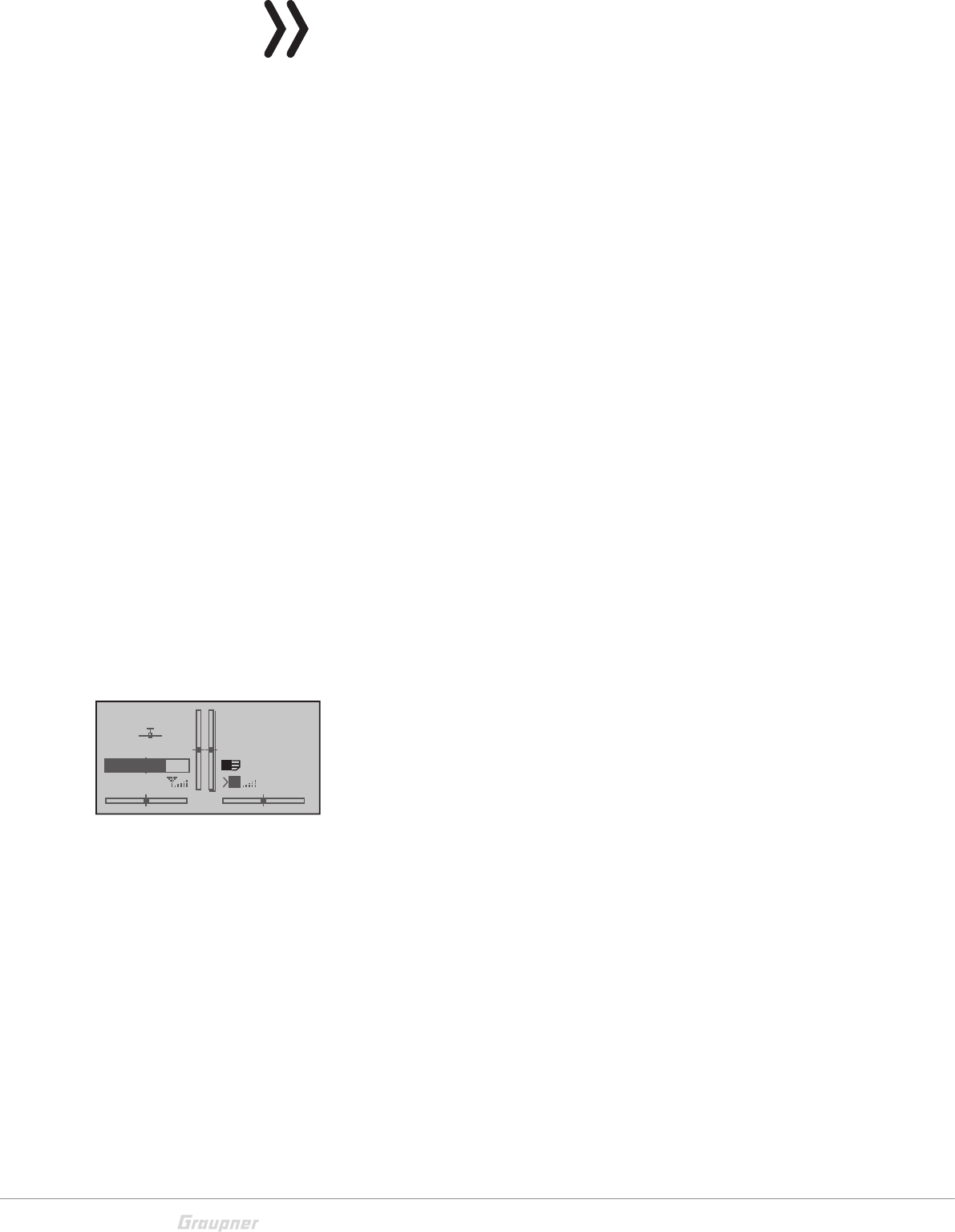
Display and touch-pad
1 Model memories 1 … 120
2 Model name
3 Model type display
4 Micro SD card (inserted)
5 Flight chronometer in min:s (forward/reverse)
6 Log timer in min:s
7 Flight phase timer display
8 Transmitter use timer
9 Phase name
10 Transmitter battery voltage with dynamic bar indicator (if the battery voltage falls below the 3.6 V (adjust-
able) threshold a warning message will appear and an acoustic warning will sound)
11 Signal power
12 M = Model function, P = Pupil
Near: Signal strength
13 Graphic display of the position of the four digital trimming levers with a direction display.
14 Operating mode
15 Receiver battery voltage RX-VOLT
Alpina 30
#11
0:51h
S
L
«normal »
0:00.0
0:00.0
4.1V
0.0V
HoTT
M
<<Akro 2 >>
0,0V
2 31 5 6
9 108 12 1411 15
4 7
13
18 / 36 S1033_jh_V1_de
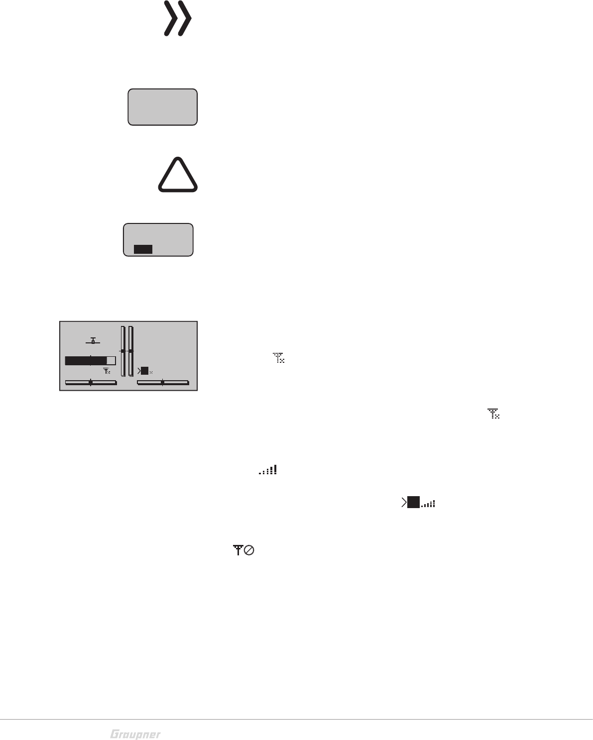
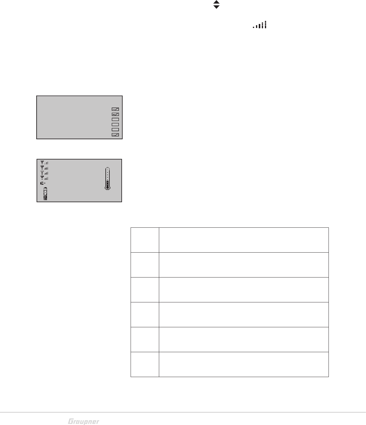
Symbols in the display
Telemetry symbols in the display
The active model memory has not yet been bound to a receiver.
Not flashing: RF transmitter function switched off.
Blinking antenna symbol: Last receiver bound to the active
model memory is inactive or out of reach
No telemetry signal to receive
Signal strength display of the model connection
Signal strength display of the connection with pupil transmitter
in the teacher transmitter display with wireless connection
Position indicator
INC/DEC buttons CTL 5 and 6
Once you activate one of the CTRL dials 5 + 6 in the middle of
the transmitter upper part, a symbol appears on the left near the
vertical trim position indicators in the lower display.
Contemporaneously the vertical position indicators change
during the operation from the trim position to the CTRL dials 5
+ 6 indicating their actual position.
The left bar shows the position of the left INC/DEC CTRL dial 5
and the right bar shows the position of the position of the right
CTRL dial 6 (both horizontal bars show the trim position of the
related sticks trims).
Approx. 2 seconds after the end of the operation of both but-
tons, the display shows again the actual trim position of the trims
(elevator/nick and throttle/pitch) of the related sticks.
Key pad
Keys left of the display
ESC button
Pressing the ESC button brings about a stepwise return to func-
tion selection or back to the basic display. Any setting changed
in the meantime is retained.
Momentarily touching the ESC key for about 1 second while in
the base screen will open and close the Telemetry menu.
Selection keys
Momentarily pressing one of these keys will cause analogous
paging in the given arrow direction through lists, e. g. through
the model selection list or the multi-function list or within menus
though the menu lines.
M
M
P
GRAUBELE
#01
2:22h
S
L
K78
0:00.0
0:00.0
RX0.0V
3.9V
M
HoTT
ESC
19 / 36
S1033_jh_V1_de
Keys to the left of the display
SET key
1. Briefly pushing the SET key will cause a jump from the dis-
played base screen to the multi-function menu.
2. In the settings menu activate (confirm) the settings fields by
pressing the SET button.
Selection keys
1. "Paging" through the multi-function menu and the menu lines
within the Basic Settings menu analogous to the arrow keys of
the left touch pad.
2. Select or set parameters in setting fields after they have been
activated by briefly touching the SET key, whereby the keys
and are used for the same corresponding functions.
3. By briefly pressing the keys simultaneously or an altered
parameter value for the active entry field will again be restored
to its default value (CLEAR).
By the mc-28 HoTT it concerns with the keypad to touch-sen-
sitive Cap-touch keys. Confirm the key by gently tapping.
Note
In the event the touch pads do not exhibit any functionality immedi-
ately after switching the transmitter off and then on again right away,
this is not a fault. Just switch the transmitter off again then wait for
several seconds before switching it on again
SET
20 / 36 S1033_jh_V1_de
Commissioning
Hand pads
Installing the hand pads
The hand pads have to be installed on the sides of the transmit-
ter. Hold the hand pad exactly upon the six holes and fix it with
the 6 fixing screws. Use the same procedure for the other hand
pad.
Attention!
Screw the fixing screws only with the hand pads on the transmitter
case. The place inside the transmitter case will otherwise not be
enough and you could damage the boards.
Removing the hand pads
The hand pads are removed by unscrewing the fixing screws.
After removing the screws glue the included rubber pins on the
holes. So you will protect the transmitter interior.
Attention!
Do not screw the fixing screws in the holes after removing the hand
pads! The place inside the transmitter case will not be enough and
you could damage the boards.
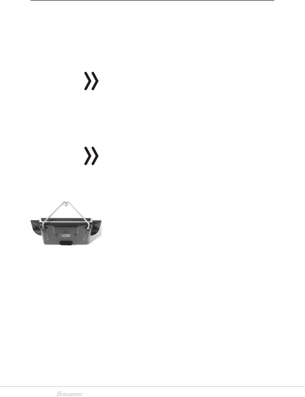
Brackets for transmitter belt
Installing the metal brackets:
Insert the included metal bracket in the bracket holder on the
side of the transmitter.
Push the bracket against the spring (approx. 1 cm in the trans-
mitter direction).
Contemporaneously rotate the bracket to the outside to fix it.
Proceed similarly with the second bracket.
Removing the metal brackets:
Unlock a bracket, by gently pushing it inwards and then fold in
the direction of the transmitter center.
Once the retaining pin is free again, you can pull the bracket
away from its place.
Proceed similarly with the second bracket.

21 / 36
S1033_jh_V1_de
Anchorage for the transmitter belt
On the upper side of the transmitter there is an eyelet which can
be used to hook a neck-strap.
Opening/closing the transmitter housing
The transmitter should be opened only in the following cases:
If a self centering stick has to be converted in non self cen-
tering
If a non self centering stick has to be converted in self cen-
tering
To set the control stick centering force
Open step by step
Before opening the housing switch the transmitter off.
Open the battery case.
Remove the battery.
If the hand rests are installed: Loosen each of the three lower
screws of the six fixing screws securing the hand pads.
Loosen the five case screws.
Hold both housing halves with both hands and let the screws
fall on a proper surface turning the transmitter upside-down.
Rotate the lower case and lay it on one side.
Attention
Never switch the transmitter on while the housing is open! Do not
touch the electronic boards.
Closing step by step:
Check if the upper and the lower part of the transmitter housing
are correctly coupled.
Screw the housing screws in their original position.
Connect the battery.
Install the hand pads again.
22 / 36 S1033_jh_V1_de
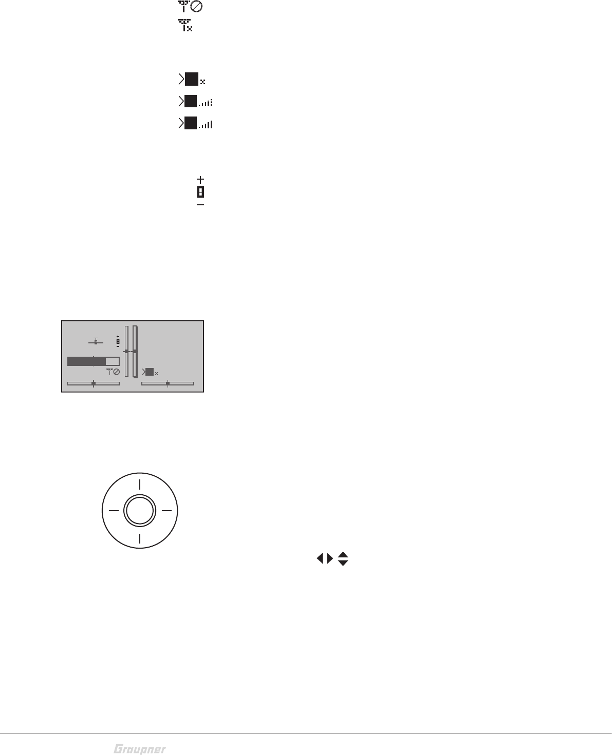
General commissioning
Notice-safety query throttle position
As soon as the transmitter is switched on then the throttle position
is checked. If the throttle position is not in the motor-off area, then
the drive motor may start in an uncontrolled manner. This check is
performed by all the models with the setting "Motor at CH1 front/
back". The warning alarm "Throttle too high" appears. For this rea-
son in this case the RF module will not be switched on. This check is
performed for every model types. With helicopter models the warning
works only if you use a Motor-off programming or if a throttle limiter
is set.
!
WARNING
If you do not follow the afore mentioned instructions, the connected
drive motor can run accidentally when the transmitter is switched on.
Risk of injury! Always program a switch for motor stop!
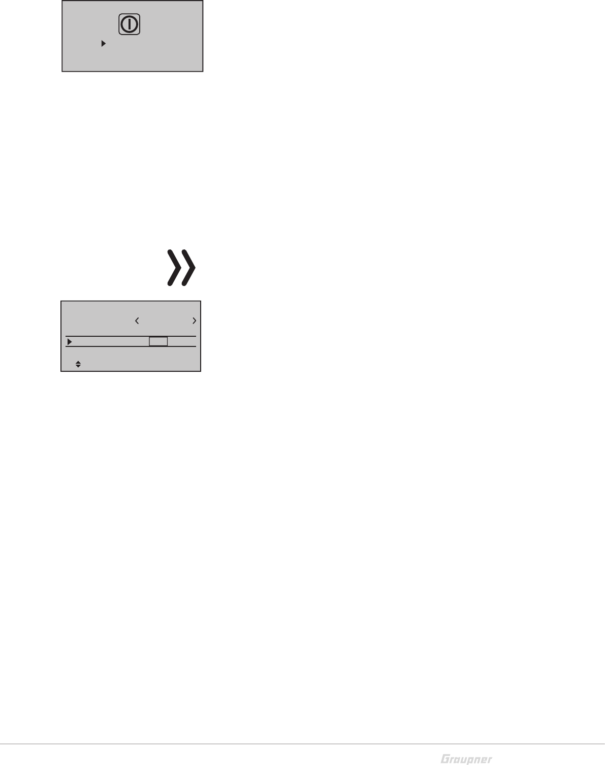
If the previously mentioned checks are passed, the RF module
will be activated when the transmitter is switched on and in the
display appears a selection indicator.
Select with the selection buttons of the right four way keys RF
ON/OFF. By tipping the SET button on "OFF" the RF module is
switched off.
The color of the lighting central LED changes to red and you are
now in the transmitter main menu display.
The symbol mean that the currently active model memory has
once been linked to a receiver but is presently not linked. (We
have turned the RF module off for example reasons.) If instead
the transmitter was switched on without turning off the RF mod-
ule, the central LED would light blue and the symbol would
blink. Contemporaneously a warning acoustic signal is emitted
until a connection is established with the respective receiver. As
soon as this connection is established appears a a field strength
indicator and the warning signal stops.
If the telemetry connection is established the respective indica-
tion of the receiver signals strength so as the actual
receiver power supply voltage.
On the other hand, if the screen displays the symbol combina-
tion and the center LED illuminates in red continuously then
the currently active model memory is not "bound" to any receiver.
Throttle
too
high!
RF on/off?
OFF
ON
Please select
GRAUBELE
#01
0:33h
Stop
Flug
K78
0:00
0:00
0.0V
5.2V
M
HoTT
M
23 / 36
S1033_jh_V1_de
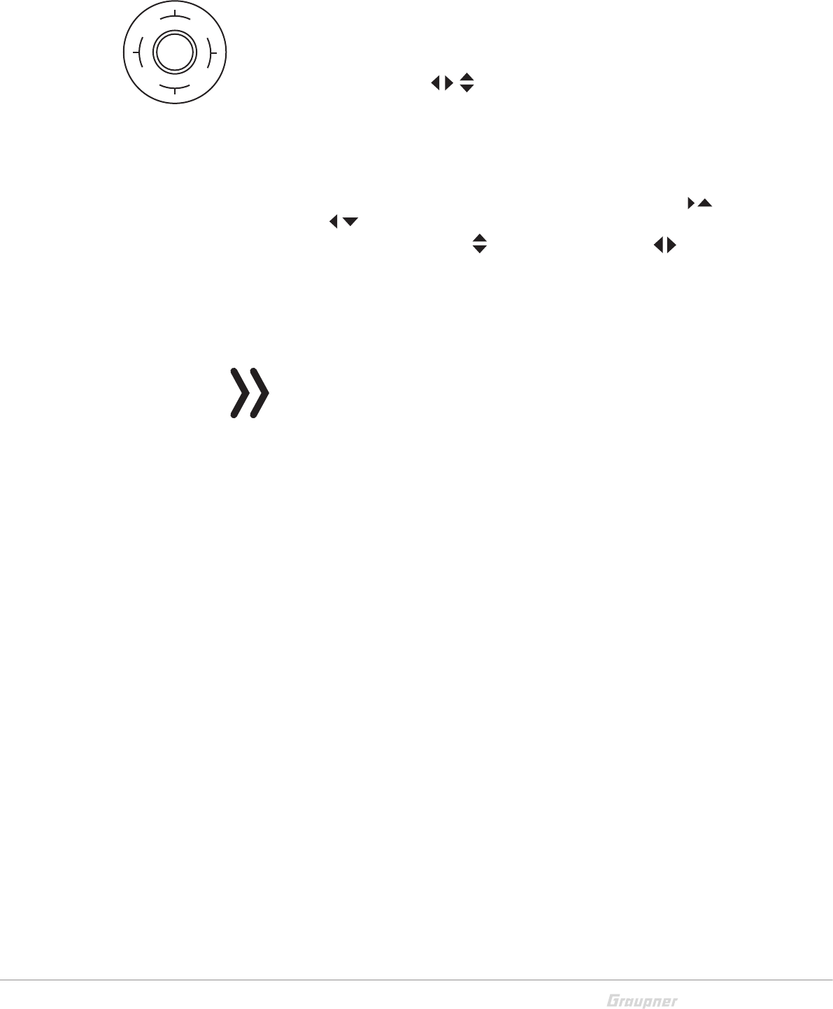
Switch the transmitter off
If you push on the POWER button, by switched on transmitter,
for more than 2 sec. a safety query appears (see image). Select
the desired option with one of the pouch pads (up or down) and
push the SET button.
This safety query avoids an accidental switch off of the transmit-
ter while in use.
Binding
The description of the binding process can be found in
the Part 2 of the manual.
To use a transmitter you must associate a receiver to the trans-
mitter. This binding process is essential for the use of the model!
The precise binding process follow-up is described in the sec-
tion "Binding" of the Part 2 of the manual and in the related
receiver manual.
NOTICE
The process is different for the various receiver types.
Binding-principle step by step:
1. Select the "main settings" menu in the transmitter
2. switch the RF module OFF
3. Connect the power supply to the receiver
... receiver with binding button:
• Push and hold the binding button at the receiver
• Start the binding process in your transmitter in the main set-
tings menu
... or receiver without binding button:
• The receiver is automatically in binding mode after switch on
• Start the binding process in your transmitter in the main set-
tings menu
4. If the binding process has been unsuccessful, repeat the
process.
Power off
Cancel
Mod.name
Stick mode 1
n/d
Base setup model
BD1
GRAUBELE
BD2
Module HoTT n/d
24 / 36 S1033_jh_V1_de
Charging the transmitter battery
You have two charge possibilities:
1. Removing the battery from its case and charging it with a
charger
WARNING
The charger should always be supervised during charge and it
should be used only in rooms fitted with a smoke detector.
Removing transmitter battery
Remove the battery case cover. Then remove and disconnect
the battery plug by carefully pulling on the supply cable.
Charge the battery following the charger manual.
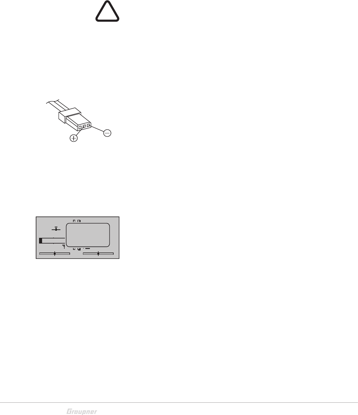
Inserting the transmitter battery
Connect the battery plug in the transmitter socket. Make sure
that the polarity is correct. Pay attention to the respective "+"
and "-" symbols near the socket.
Red= + Black/brown = -
Place the battery into its compartment and close the cover.
2. Through the USB port by charging with USB cable
The transmitter battery can be charged by the current supplied
by the USB port (5V/max. 2A).
Connect the transmitter to a USB port in your PC using the
included micro USB cable or a USB net charger.
Low voltage warning
The transmitter battery voltage should be monitored in the dis-
play during operation. In case the voltage drops under a preset
threshold, standard setting 3,6 V, an acoustic warning signal is
emitted and in the display appears in a window "battery needs
charging".
Now at the latest, the operation must be stopped and the trans-
mitter battery must be charged!
Battery use timer in the display
The battery use timer is shown in the lower left part of the dis-
play.
The battery use time is added at every use. After every charge
the timer is reset to "00:00". This happens only if the battery volt-
age increases at least of 0,3V or if the battery is full.
Lithium battery
On the transmitter board there is a replaceable lithium battery of
type CR 2032. This battery maintains the date and time settings
during a transmitter power supply outage.
!
GRAUBELE
#01
0:22h
S
Flug
«normal »
K78
0:00.0
0:00.0
0.0V
3.5V
Mx
x
HoTT
Batt. must
be re-
charged !!

25 / 36
S1033_jh_V1_de
Use and menu functions
Short-Cuts
The following key combinations can be used to directly call up
certain menus and options:
CLEAR
Brief simultaneous touch of the keys or on the right four
way keys will restore the active entry field's changed parameter
value back to its default value.
"Servo screen"
Brief simultaneous activation of the keys of the left four-way
keys will cause a jump from the transmitter's base screen or
from almost any menu position to the "Servo display" menu,
"Telemetry" menu
Press the center ESC key in the left four-way keys for about 1 s
to call up the "Telemetry" menu from the transmitter's base
screen.
To come back to the base screen it is enough a "normal" touch
on the ESC key.
Graphic display of telemetry data
Briefly touching one of the arrow keys of the left or right four-way
keys will cause a jump from the base screen directly to the trans-
mitter's graphic display of telemetry data or will allow paging
back and forth between individual graphic displays.
Briefly touching the ESC or SET key will cause a return back to
the base screen.
"HIDDEN MODE"
Press and hold arrow keys of the left four-way keys then
momentarily touch the SET key of the right four-way keys.
Entry lock
Entry lockout is activated and deactivated from the base screen
by simultaneously pressing the ESC and SET keys for a little lon-
ger. The entry lock function is displayed by a key symbol:
The controls remain operational.
Press the ESC and ENT buttons again for about two second to
release the lock.
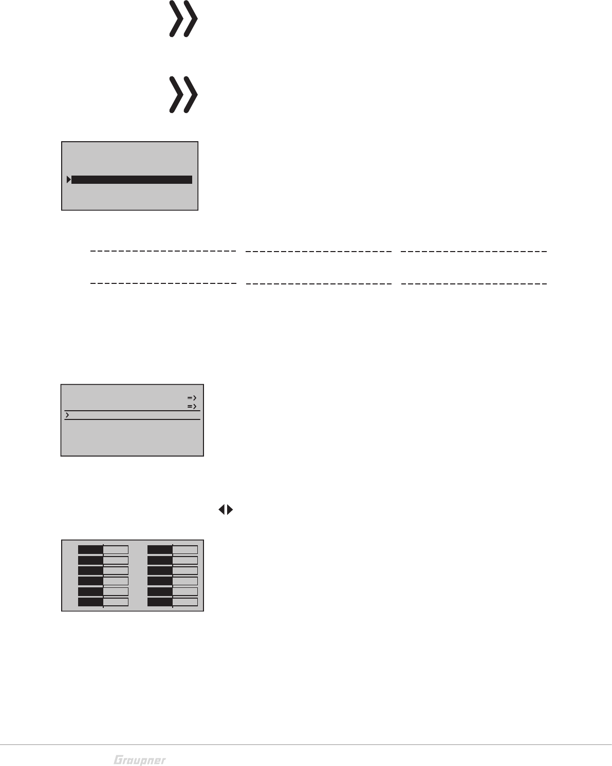
Quick-Select
From the multi-function list, a jump can be made to a "Structure
overview" by a simultaneous touch on the or keys of the
right four-way keys.
26 / 36 S1033_jh_V1_de
Menus are arranged in clear groups in this overview.
Select the desired group with the selection keys and confirm
this selection with the SET key.
Only the menu points associated with the selected preamble are
shown.
Select the desired menu point with the selection keys and con-
firm with the SET key.
The description of the single menu point is available in the pro-
gramming manual (Manual part 2) on www.graupner.de.
Hidden menu options
In some menus specific setting options are available but hidden.
These options are marked with a triangle oriented to the right in
the low left corner of the display. In the left represented menu
the section "- limit +" on the right of the "- trvl. +" is hidden.
View hidden sections:
Follow the triangle oriented to the right in the lower part of the
display, in which you skip the selection frame with the selection
key over the section "- trvl. +" to the right.
To come back to the "- trvl. +" or more to left, follow the triangle
oriented to the left, on which you can move the selection frame
moving the related selection key to the left.
Use the same procedure for the other menus.
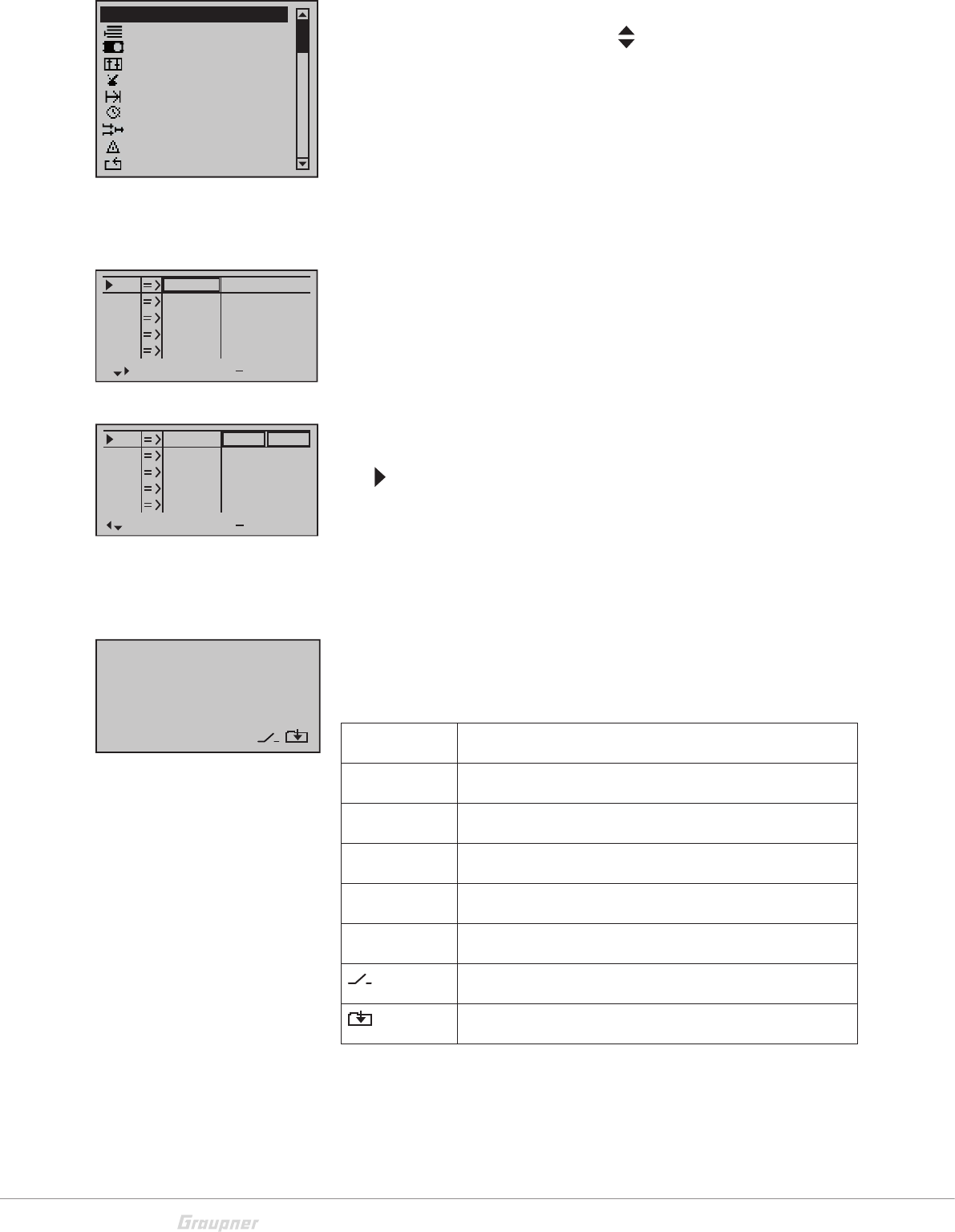
Function field in the display
Depending on the given menu, certain function fields will appear
on the bottom display line.
A marked function is activated by pushing the SET key.
CLR (CLEAR) Delete
SEL (SELECT) Selection
SET (SET) Setting
STO (STORE) Store
SYM Set values symmetrically
ASY Set values asymmetrically
Switch symbol field (assignment of all types of switches)
Within a menu, change to the next page
Memory
Servo setting
Transm. controls
Switches
Flight phases
Timers
Mixers
Sepecial funct.
Global functions
All menus
S1
S2
S3
Rev cent +
trv
0%
0%
0%
100% 100%
100% 100%
100% 100%
0%
0%
100% 100%
100% 100%
S4
S5
S1
S2
S3
Rev cent +
trv
0%
0%
0%
150% 150%
150% 150%
150% 150%
0%
0%
150% 150%
150% 150%
S4
S5
CLR SEL STO SYM ASY

27 / 36
S1033_jh_V1_de
Hidden mode
The menu "Hidden Mode" can be reached from any menu posi-
tion.
Press and hold the selection key of the left four way keys and
the SET key.
Announcements
These messages are in German by default. These announce-
ments are summarized in a voice packet which is stored in a
transmitter-internal memory but they can be replaced by a voice
packet of a different language at any time.
Here you can also load user speech packets in the transmitter.
These packets must be created in the "Firmware upgrade stu-
dio" as .wav files and they must be saved in the SD card.
On the included micro SD card are already available the follow-
ing languages: German, English, French, Dutch, Italian and
Spanish, Czech and Russian.
The most actual language packets are available on the web site
www.graupner.de.
Language change
Language change step by step:
Insert the included memory card in its slot as described in the
"Memory card" section.
Switch the transmitter on with the RF module on.
Change in the "Secret mode" menu.
Move to the line "ANNOUNCEMENT" by using the selection
keys.
Select the "ANNOUNCEMENT" option with the SET key.
Select the language or the user speech packet with the selec-
tion keys.
Confirm by pressing the SET key. The selected language packet
will be stored in the transmitter memory.
The loading process is finished as soon as the progress bar at
the lower edge of the display disappears.
When this process is finished, switch the transmitter off.
Note
If the warning message "RF OFF OK", the RF module is still active.
Switch the RF module off and repeat the process,
Note
If the data list is empty. the transmitter is not finding any valid lan-
guage data in the SD card. Verify the content of the "VoiceFile" folder
in the SD card by a PC.
HIDDEN MODE
VOICE
STICK CALI.
FIRMWARE UPDATE
BLUETOOTH INIT.
FILE LIST
MC-28_FRANCE.VDF
MC-28_SPAIN.VDF
MC-28_ENGLISH.VDF
MC-28_GERMAN.VDF
MC-28_ITALIANO.VDF
MC-28_DUTCH.VDF
28 / 36 S1033_jh_V1_de
Firmware update/Changing the display language
Note
Before each update, check the transmitter battery charge or charge
it as a precaution, and save all model memories so that they can be
restored if necessary.
Note
Follow the "Firmware update step by step" manual steps from the
section "Firmware update" "Update per memory card".
Firmware update step by step:
Move with a short pressure on the SET key to the selection page
of the option "FIRMWARE UPDATE".
Select the firmware version with the selection keys.
Confirm by pushing the SET key.
The storing in the transmitter memory will start:
When the counter reaches the storing amount the storage pro-
cess is finished and the message "Firmware upgrade success!"
appears.
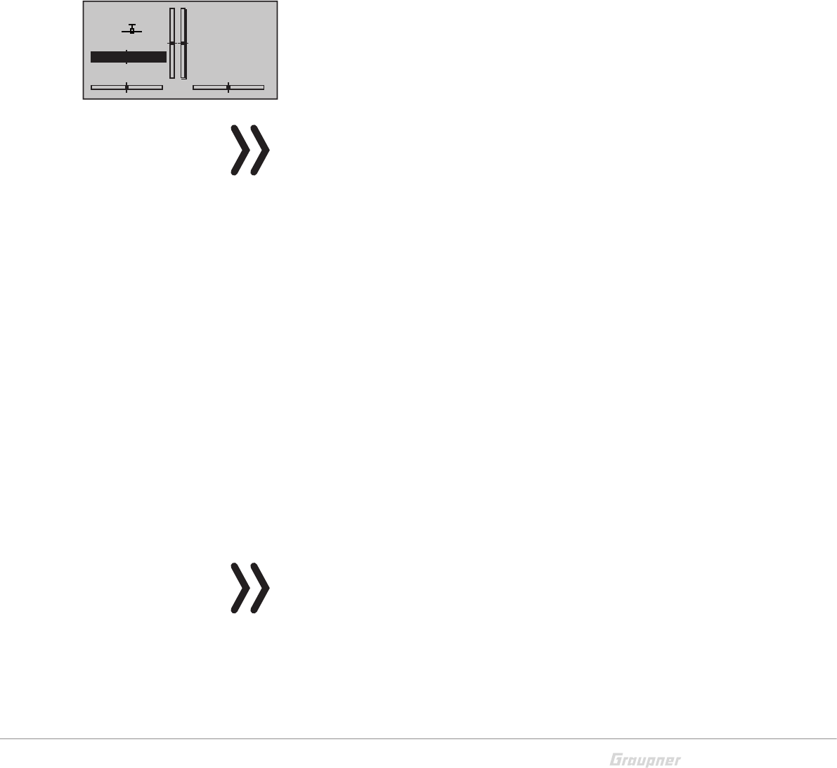
Stick calibration
If the center position of your self-neutralizing control stick does
not precisely correspond to 0% control travel, you can check
and correct it as follows:
Stick calibration step by step:
Move to the "Model select" menu and initialize a free model
memory.
Move to the "Servo display" menu, pressing simultaneously the
keys in the left touch pad, without any interim change to trim
settings or other program settings.
In this menu point you can check if your sticks are correctly cen-
tered. Bring then all the sticks in the middle position. If the sticks
are correctly placed, this display should ideally look like the one
shown on the left.
One after the other, put both sticks into each of their four pos-
sible limit positions without exerting force at the limit position
and check if the value are between -100% and +100%.
If you note that the sticks do not reach the desired values, move
to the "Stick calibration" line in the "HIDDEN MODE" menu and
tip on the SET key.
FILE LIST
MC-20_1V234_German.b
MC-20_1V234_France.
MC-20_1V234_Dutch.bi
MC-20_1V234_Italiano
MC-20_1V234_Spain.bi
MC-20_1V234_English.b
Firmware Download
Prozess Start
Please Wait....
Boot Download
Success!!!
Please Wait....
Firmware
Downloading...
Progress 023/208
HIDDEN MODE
VOICE
STICK CALI.
FIRMWARE UPDATE
BLUETOOTH INIT.
NEUTRAL ZONE
1
3
5
7
+
0%
0%
9
11
0%
0%
2
4
6
8
+
0%
0%
0%
0%10
12 0%
–100%
0%
0%

29 / 36
S1033_jh_V1_de
The flashing arrows indicate in which direction you have to push
the sticks.
Confirm by pushing the SET key.
With the selection keys of the right four way keys allow you
to cyclically select the positions of the four calibrated sticks.
Pushing the ESC key will terminate the process and return to the
sub-menu "Stick cali.".
Example: Bring here the respective left blinking selection arrow
of the right stick to the left limit. Tip on the SET key. Push the
SET key. So the calibration of the right stick left limit. The circle
in the middle of the stylized stick blinks as confirmation.
Slider control calibration
Here both central slide controls (SR1-2) and the lateral lever
controls (SD1-2) are calibrated. The blinking arrows indicate you
in which direction you have to move the controls.
With the selection keys of the right four way keys allow you
to cyclically select the positions of the four calibrated controls.
Proceed as described in the upper example.
UVG (Universal control) calibration
Here are calibrated the travels of the control of the 4D control
stick or the optionally installed rotary control. Proceed as
described in the upper example.
Bluetooth initialization
In this display you can initialize the Bluetooth module. The menu
is only for service functions, this process has already performed
in the factory.
Neutral zone
In this menu you can calibrate the "dead" zone in the central
point of the sticks and controls, so that in this zone there is no
control movement. Menu only appears when the Stick type is
set as 4D-Stick at basic setting.
Push the SET button, increase the lower left value until the end
point is no longer visible in the central line. Perform this process
for all the four stick directions and both rotary controls. With the
selection keys of the right four way keys allow you to cycli-
cally select the positions of the calibrated travels (1 to 6).
STICK CALIBRATION
CONTRAST
LANGUAGE
0
VOICE DEUTSCH
ENGLISH
STICK CALI.
0%
STICK CALIBRATION
CONTRAST
LANGUAGE
0
VOICE DEUTSCH
ENGLISH
STICK CALI.
+102%
SLIDE CALIBRATION
CONTRAST 0
VOICE DEUTSCH
ENGLISH
+102%
UVG CALIBRATION
CONTRAST 0
VOICE DEUTSCH
ENGLISH
+7%
HIDDEN MODE
VOICE
STICK CALI.
FIRMWARE UPDATE
BLUETOOTH INIT.
NEUTRAL ZONE
HIDDEN MODE
VOICE
STICK CALI.
FIRMWARE UPDATE
BLUETOOTH INIT.
NEUTRAL ZONE
NEUTRAL ZONE RATE
CONTRAST 0
VOICE DEUTSCH
ENGLISH
+7%
1: 1.7
30 / 36 S1033_jh_V1_de
Telemetry data display
Sensors
The upper display serves as graphical representation of the
telemetry data.
If a receiver is bound the telemetry display appears. By tipping
again the selection keys , you can select which sensor or
module you want to be displayed.
If instead there are two "X" instead of in the lower part of
the display and it appears the message "CAN'T RECEIVE ANY
DATA", it means that there is no connection between receiver
and transmitter and that no telemetry data is available. Turn on
your receiver, or bind a receiver to the active model memory.
Depending on the connected modules and sensors, several
selectable displays will appear. The description of these displays
is contained in the manual included in the sensor package.
The transmitter recognizes automatically the sensors. You can
view the sensors by changing from the main menu to the telem-
etry menu. The sensors will be listed in the display and marked
with a check mark.
Receiver
This display offers a graph of the data from the display "RX DAT-
AVIEW“ of the "Telemetry" menu "SETTINGS, DISPLAYS".
Value Explanation
RX-S
QUA
Quality expressed as a percentage of the signal packages from
the transmitter arriving at the receiver
RX-S ST Signal strength expressed in percentage of the signal from the
transmitter arriving at the receiver
RX-dBm Level in dBm expressed as the percentage of the transmitter
signal arriving at the receiver
V PACK Level in dBm expressed as the percentage of the receiver
signal arriving at the transmitter
TX-dBm Shows the longest time in ms in which the data packets are
lost during a transmission from the transmitter to receiver
RX-VOLT Current operating voltage of thereceiver power supply in Volts
SENSOR SELECT
RECEIVER
GENERAL MODULE
VARIO MODULE
ELECTRIC AIR MOD.
GPS
ESC
RX–S QUA: 100%
RX–S ST.: 100%
TX–dBm: –33dBm
RX–dBm: –33dBm
RX–SPG.:4.8V TMP
V–PACK: 10ms
CH OUTPUT TYPE:ONCE
M–RX V :4.6V +22°C

31 / 36
S1033_jh_V1_de
M-RX V Lowest operating voltage of thereceiver power supply since
the last startup in Volts
TMP The thermometer visualizes the current operating temperature
of the receiver

32 / 36 S1033_jh_V1_de
Firmware update
The programs and files which are also required for updating the
transmitter combined into one software package can be down-
loaded from www.graupner.de.
Download this software package from the Internet, and unpack
it on your computer. All other information can be found in inter-
net in the same page where the software package is available.
Firmware updates of the transmitter can be performed in two
ways.
Update through memory card
Update through USB port
Note
Please note that compatible firmware is required for reliable
communication between the HoTT components. The programs
and files that are required to update are therefore combined into
a single file.
The current firmware version can be found on the Internet at
www.graupner.de.
Only operate your transmitter using the current software version.
these information can also be found at: www.graupner.de =>
Service & Support => Update and revision history for GRAUPNER
HoTT components.
Before each update, check the transmitter battery charge or
charge it as a precaution, and save all model memories so that
they can be restored if necessary.
Do not disconnect the link to the computer during an update!
Make sure that the link between the transmitter and computer is
operational.
After each update, check to make sure that the models function
correctly.
Update through memory card
Download the actual software package from the Internet, and
unpack it on your computer. Insert the supplied mini SDCard in
the card slot of your PC and copy the required firmware file from
the unpacked software package into the directory "Firmware“
on the memory card. Then, remove the memory card from the
PC and insert it in the card slot of the transmitter. Switch on the
transmitter and the RF module off.
Go to the sub-menu "FIRMWARE UPDATE" in the menu "Hid-
den mode" and proceed as described in the "Hidden mode"
section.

33 / 36
S1033_jh_V1_de
Update through USB port
Download the actual software package from the Internet, and
unpack it on your computer. Connect your switched off trans-
mitter with your PC, by using the included USB cable, which is
supplied with the package content, plug USB cable directly to
the micro USB port of the transmitter and the other end to a free
port in your computer. All other information can be found in the
instructions that come in the software package.
Problems during firmware update
Problem: POWER switch without function
If a firmware update for the transmitter is unsuccessful or the
transmitter program freezes and the transmitter cannot be
turned off using the "POWER" switch, then remove the transmit-
ter's battery after setting the switch to "POWER = OFF" position,
or pull the plug from the transmitter battery, reconnect it after
few seconds and leave the transmitter switched OFF.
Download the actual update file from internet and save it in the
"RECOVERY" folder in your SD card. The change the file name
in "R280.bin".
Insert the SD card in the transmitter.
Push and hold the Ctl 5 and Ctl 6 buttons at the same time to
the top and push the POWER button.
Now push and hold to the lower side within 2 - 3 seconds the
Ctl 5 and Ctl 6 for about 10 seconds.
Wait then at least 30 seconds. In the display will be shown no
image. During the update the transmitter cannot be switched
on.
After 30 seconds the transmitter switches on.
Declaration of conformity
S1033 mc-28 HoTT
Graupner/SJ declares that the product is conform to EU norms.
EMV 2004/108/EC:
EN 301 489-1 V1.9.2
EN 301 489-17 V2.1.1
EN 62479:2010
LVD 2006/95/EC:
EN 60950-1 + A11 + A1 + A12 + A2:2013
R&TTE 1999/5/EC:
EN 300 328 V1.8.1
EN 62311:2008
34 / 36 S1033_jh_V1_de
Notes on environmental protection
Disposal notes
This symbol on the product, user manual or packaging indicates
that this product must not be disposed of with other household
waste at the end of its life. It must be handed over to the appli-
cable collection point for the recycling of electrical and electronic
equipment.
The materials are recyclable as marked. By recycling, material
reusing or other forms of scrap usage you are making an import-
ant contribution to environmental protection.
Batteries and accumulators must be removed from the device
and disposed of at an appropriate collection point. Please inquire
if necessary from the local authority for the appropriate disposal
site.
Care and maintenance
Notes on care
The product does not need any maintenance, it works so as it
is without any special care. In your own interests protect it from
dust, dirt and moisture.
Warranty
The Graupner, Henriettenstrassee 96, 73230 Kirchheim/Teck
grants from the date of purchase of this product for a period of
24 months. The warranty applies only to the material or opera-
tional defects already existing when you purchased the item.
Damage due to misuse, wear, overloading, incorrect accesso-
ries or improper handling are excluded from the guarantee. The
legal rights and claims are not affected by this guarantee. Please
check exactly defects before a claim or send the product,
because we have to ask you to pay shipping costs if the item is
free from defects.
The present construction or user manual is for informational pur-
poses only and may be changed without prior notice. The cur-
rent version can be found on the Internet at www.graupner.de on
the relevant product page. In addition, the company Graupner
has no responsibility or liability for any errors or inaccuracies that
may appear in construction or operation manuals.
No liability can be accepted for printing errors.
P
ICwarning
This device complies with Industry Canada licence-exempt RSS standard(s).
Operation is subject to the following two conditions:
(1) This device may not cause interference and (2) this device must accept any interference,
including interference that may cause undesired operation of the device.
Le présent appareil est conforme aux CNR d'Industrie Canada applicables aux appareils radio
exempts de licence.L'exploitation est autorisée aux deux conditions suivantes :
(1) l'appareil ne doit pas produire de brouillage, et
(2) l'utilisateur de l'appareil doit accepter tout brouillage radioélectrique subi, même si le brouillage
est susceptible d'en compromettre le fonctionnement.
Under Industry Canada regulations, this radio transmitter may only operate using an antenna of a
type and maximum (or lesser) gain approved for the transmitter by Industry Canada. To reduce
potential radio interference to other users, the antenna type and its gain should be so chosen that
the equivalent isotropically radiated power (e.i.r.p.) is not more than that necessary for successful
communication.
Conformément à la réglementation d'Industrie Canada, le présent émetteur radio peut
fonctionner avec une antenne d'un type et d'un gain maximal (ou inférieur) approuvé pour
l'émetteur par Industrie Canada. Dans le but de réduire les risques de brouillage
radioélectrique à l'intention des autres utilisateurs, il faut choisir le type d'antenne et son gain de
sorte que la puissance isotrope rayonnée équivalente (p.i.r.e.) ne dépasse pas l'intensité
nécessaire à l'établissement d'une communication satisfaisante.
This radio transmitter (identify the device by certification number, or model number if Category II)
has been approved by Industry Canada to operate with the antenna types listed below with the
maximum permissible gain and required antenna impedance for each antenna type indicated.
Antenna types not included in this list, having a gain greater than the maximum gain indicated for
that type, are strictly prohibited for use with this device.
Le présent émetteur radio (identifier le dispositif par son numéro de certification ou son
numéro de modèle s'il fait partie du matériel de catégorie I) a été approuvé par Industrie
Canada pour fonctionner avec les types d'antenne énumérés ci-dessous et ayant un gain
admissible maximal et l'impédance requise pour chaque type d'antenne. Les types d'antenne non
inclus dans cette liste, ou dont le gain est supérieur au gain maximal indiqué, sont strictement
interdits pour l'exploitation de l'émetteur.
FCC Warning
This device complies with Part 15 of the FCC Rules. Operation is subject to the following two
conditions
(1) this device may not cause harmful interference, and
(2) this device must accept any interference received, including interference that may cause
undesired operation. Changes or modifications not expressly approved by the party responsible
for compliance could void the user’s authority to operate the equipment.
Note 1: This equipment has been tested and found to comply with the limits for a Class B digital
device, pursuant to part 15 of the FCC Rules. These limits are designed to provide reasonable
protection against harmful interference in a residential installation. This equipment generates,
uses and can radiate radio frequency energy and, if not installed and used in accordance with the
instructions, may cause harmful interference to radio communications. However, there is no
guarantee that interference will not occur in a particular installation. If this equipment does
cause harmful interference to radio or television reception, which can be determined by turning
the equipment off and on, the user is encouraged to try to correct the interference by one or
more of the following measures:
—Reorient or relocate the receiving antenna.
—Increase the separation between the equipment and receiver.
—Connect the equipment into an outlet on a circuit different from that to which the receiver is
connected.
—Consult the dealer or an experienced radio/TV technician for help.
Note 2: 1.Changes or modifications to this unit not expressly approved by the party responsible
for compliance could void the user’s authority to operate the equipment.