GRAUPNER 16007812 2.4GHz transmitter User Manual S1002 PRO mz 12PRO Teil 1 EN indd
GRAUPNER CO., LTD. 2.4GHz transmitter S1002 PRO mz 12PRO Teil 1 EN indd
GRAUPNER >
User Manual
EN
No. S1002.PRO
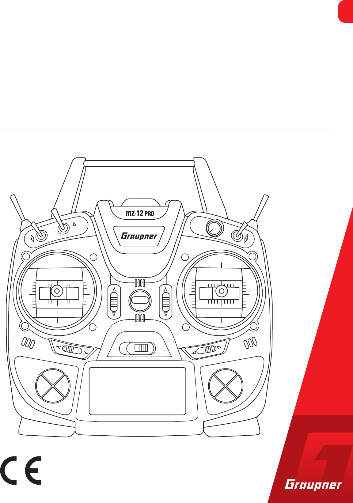
mz-12PRO HoTT
Manual
Copyright © Graupner/SJ GmbH
12 channel 2,4 GHz transmitter
Manual part 1
EN


3 / 28
S1002.PRO_jh_V1
Index
Introduction ............................................................................. 5
Service Centre .......................................................................... 5
Intended use ............................................................................ 6
Target group .................................................................................... 6
Package content ....................................................................... 6
Technical data .......................................................................... 7
Symbols explication ................................................................. 7
Safety notes.............................................................................. 7
For your safety by handling the transmitter ..................................8
For your safety by handling the battery .........................................9
Description of the transmitter ............................................... 11
Control elements on the transmitter ...........................................11
Connections and fixtures .............................................................. 13
Attaching the transmitter neck-strap ........................................... 13
Jack socket .................................................................................... 13
Data socket.................................................................................... 13
Micro USB charging socket ........................................................... 13
Display and touchpad ...................................................................14
Symbols in the display ..................................................................14
Symbols in the info list .................................................................. 14
Display of the transmitter mode .................................................. 14
Commissioning ....................................................................... 15
Settings by the first use ................................................................15
Start display .................................................................................. 15
Control sticks length adjustment .................................................. 16
Opening/closing the transmitter housing .................................... 16
Neutralizing the control sticks ...................................................... 17
Brake spring and ratchet ............................................................... 17
Control sticks centering force ....................................................... 17
General commissioning ................................................................18
Binding ..........................................................................................18
Transmitter power supply .............................................................18
Inserting the battery ..................................................................... 18
Battery charging ............................................................................ 18
Low voltage warning ..................................................................... 20

4 / 28 S1002.PRO_jh_V1
Battery use timer in the display....................................................20
Use and menu functions ........................................................ 20
Four-way keys ...............................................................................20
Short-Cuts .....................................................................................21
Function field in the display ......................................................... 22
Hidden mode ................................................................................22
Stick calibration ............................................................................. 22
Servo display .......................................................................... 23
Firmware update .................................................................... 25
Transmitter software update ........................................................25
Declaration of conformity ...................................................... 26
Notes on environmental protection ...................................... 27
Care and maintenance ........................................................... 27
Warranty ................................................................................ 27
5 / 28
S1002.PRO_jh_V1
Introduction
Thank you very much for purchasing a Graupner mz-12PRO HoTT
transmitter.
Read this manual carefully to achieve the best results with your
transmitter and first of all to safely control your models. If you expe-
rience any trouble during operation, take the instructions to help or
ask your dealer or Graupner Service Centre.
Notice
This manual is composed by two parts. Part 1 is contained in the
product's package content. Part 2 can be found in its last version on
www.graupner.de by the related item page.
Due to technical changes, the information may be changed in this
manual without prior notice. Keep updated by regularly checking
our own website, www.graupner.de to be always updated with the
products and firmware.
This product complies with national and European legal require-
ments.
To maintain this condition and to ensure safe operation, you must
read and follow this user manual and all the safety notes before
using the product!
Note
This manual is part of that product. It contains important informa-
tion concerning operation and handling. Keep these instructions for
future reference and give it to third person in case you gave the
product.
Service Centre
Graupner Central Service
Graupner/SJ GmbH
Henriettenstrasse 96
D-73230 Kirchheim / Teck
Servicehotline
(+49) (0)7021/722-130
Monday - Thursday:
9:15 am - 4:00 pm
Friday:
9:15 am - 1:00 pm
service@graupner.de
Graupner USA
3941 Park Dr Suite 20-571
El Dorado Hills, CA 95762
Website: www.graupnerusa.com
Phone: +1 855-572-4746
Email:service@graupnerusa.com
Graupner in Internet For the service centers outside Germany please refer to our web site
www.graupner.de

6 / 28 S1002.PRO_jh_V1
Intended use
This remote-control system may only be used for the purpose spec-
ified by the manufacturer for operation of remote control models
without passengers. Any other type of use is impermissible and may
damage the system and cause significant property damage and/or
personal injury. No warranty or liability is therefore offered for any
improper use not covered by these provisions.
Read through this entire manual before you attempt to install or use
the transmitter.
Graupner/SJ constantly works on the development of all products;
we reserve the right to change the item, its technology and equip-
ment.
Target group
The product is not a toy. It is not suitable for children under 14 years.
The operation of the mz-12PRO HoTT transmitter must be per-
formed by experienced modelers. If you do not have sufficient knowl-
edge about dealing with radio-controlled models, please contact an
experienced modeler or a model club.
Package content
Transmitter mz-12PRO HoTT
LiPo transmitter battery
Transmitter strap
Receiver (optional)
Transmitter manual (Part 1)
Receiver manual (optional)
The programming manual (manual part 2) can be found in its last
version on www.graupner.de by the related item page.
7 / 28
S1002.PRO_jh_V1
Technical data
Transmitter mz-12PRO HoTT
Frequency band 2,4 … 2,4835 GHz
Modulation FHSS
Transmitting power 100 mW EIRP
Control functions 12 functions of which 4 can be trimmed
Temperature range -10 … +55 °C
Antenna Integrated antenna
Operating voltage 3,4 … 5,5 V
Power consumption approx. 180 mA
Dimensions approx. 190 x 185 x 90 mm
Weight approx. 700 g with batteries
Note
The technical data of the optional receiver are available in the man-
ual included in the receiver package content.
Symbols explication
Always observe the information indicated by this warning sign. Par-
ticularly those which are additionally marked with the CAUTION or
WARNING. The signal word WARNING indicates the potential for
serious injury, the signal word CAUTION indicates possibility of
lighter injuries.
The signal word Note indicates potential malfunctions.
Attention indicates potential damages to objects.
Safety notes
These safety instructions are intended not only to protect the prod-
uct, but also for your own and other people’s safety. Therefore please
read this section very carefully before using the product!
Do not carelessly leave the packaging material lying around,
since it might become a dangerous toy for children.
Persons, including children, with reduced physical, sensory or
mental capabilities, or lack of experience or knowledge, or not
capable to use safely the transmitter must not use the transmit-
ter without supervision or instruction by a responsible person.
Operation and use of radio-controlled models needs to be
learned! If you have never operated a model of this type before,
start carefully and make yourself familiar with the model's reac-
tions to the remote control commands. Proceed always respon-
sibly.
!
!
8 / 28 S1002.PRO_jh_V1
Before you start using the remote control model, you have to
check the further relevant laws and regulations. These laws you
must obey in every case. Pay attention to the possibly different
laws of the countries.
The insurance is mandatory for all kinds of model operation. If
you already have one, so please inform yourself if the operation
of the respective model is covered by your insurance. If this is not
the case, conclude a special liability insurance policy for models.
Protect all equipment from dust, dirt, moisture. All equipment
must be protected from vibration as well as excessive heat or
cold. The models may only be operated remotely in normal out-
side temperatures such as from -10°C to +55°C.
First, always perform a range and function test on the ground
before you start using your model. Only so you can grant a safe
use! How to perform a range test is explained in the Part 2 of the
manual.
Only operate ALL your HoTT components using the current soft-
ware version.
Start a data log every time you use your model. With a log-data
an occurred technical defect can be recognized and verified.
Only so it is possible to considerate an eventual compliant.
For your safety by handling the transmitter
WARNING
Also while programming the transmitter, make sure that a con-
nected motor cannot accidentally start. Disconnect the fuel sup-
ply or drive battery beforehand.
CAUTION
Risk of fire! Avoid every kind of short-circuit in all sockets of the
transmitter! Use only the suitable connectors. In no case the elec-
tronic component of the transmitter may be changed or modified.
Due to licensing reasons, any reconstruction and/or modification
of the product is prohibited.
Inform yourself before flying your
model on which maximum altitude
you can fly in the uncontrolled
airspace over the starting position
and do not exceed it.
!
!
9 / 28
S1002.PRO_jh_V1
Note
During transport protect the model and the transmitter from dam-
ages.
For your safety by handling the battery
CAUTION
Protect all equipment from dust, dirt, moisture. Only use in dry
locations.
Do not use any damaged battery. Risk of injury!
Any alterations to the battery can cause serious injury. Risk of
fire!
Batteries may not be heated, burned, short-circuited or charged
with excessive current or with reversed polarity.
While they are being charged, the batteries must be placed on a
non-flammable, heat-resistant and non-conductive surface.
Combustible or highly flammable objects are to be kept away
from the charging area. Batteries must be monitored while they
are being charged.
The maximum quick charging current specified for the respec-
tive cell type may not be exceeded.
If the battery heats up above 60°C while it is being charged, stop
charging and let the battery cool down to approximately 30 -
40°C.
Never charge batteries that have already been charged, are hot
or are not fully discharged. If a cell in a battery pack has become
particularly hot following a quick-charge process, this may indi-
cate a defect in that cell. Do not use the battey pack any more!
The batteries must not be modified. Do not directly solder or
weld the cells.
If handled improperly, there is a danger of fire, explosion, irrita-
tion and burns. To extinguish a fire use: water, CO2, sand.
Leaked electrolyte is caustic and should not be touched or come
into contact with your eyes. In case of emergency, rinse with a
large quantity of water and consult a Med. Doctor.
Always charge the battery fully.
The maximum charging current permitted may not be exceeded.
Never leave the charger unattended when it is connected to the
power supply.
Please charge your batteries only in rooms fitted with a smoke
detector.
!

10 / 28 S1002.PRO_jh_V1
Special instructions
To charge and discharge batteries, only use specifically designed
chargers/dischargers with balancer connector.
The white connector (cell count + 1 pole) is designed for the con-
nection to a LiPo balancer or a battery charger as a single cell
charger with a manual cell balancer. Always charge the battery
with the balancer connector.
Safety notes for stocking batteries
Batteries may only be stored in non completely discharged con-
dition.
Batteries may only be stored in dry rooms with an ambient tem-
perature of +5°C to +25°C.
Stock the LiPo batteries with a cell voltage of about 3,8V. If the
cell voltage falls below 3 V, then the battery must be necessarily
charged. Deep discharge and storage in discharge status (cell
voltage < 3V) make the battery useless.
Charge and transport your batteries always in a safety bag.
11 / 28
S1002.PRO_jh_V1
Description of the transmitter
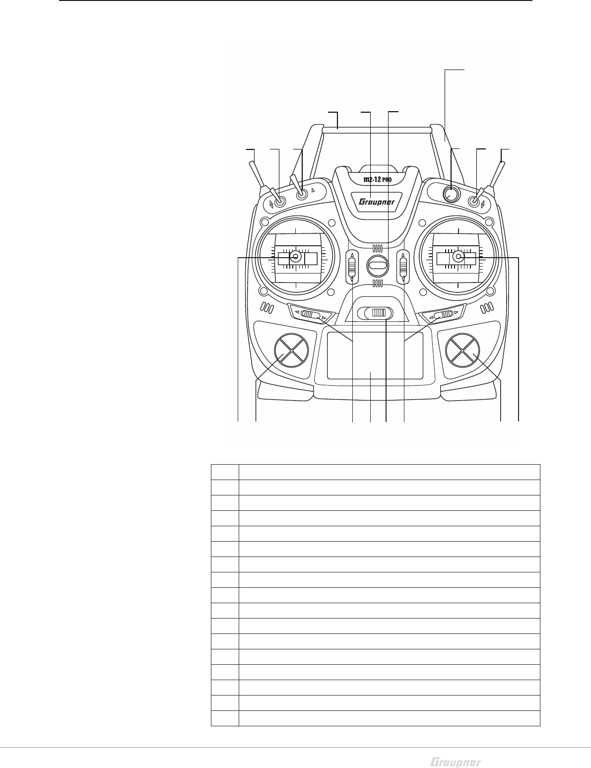
Control elements on the transmitter
1 Integrated antenna
2 Eyelet for neck strap
3 Proportional dial DV
4 2 way switch SW 3
5 3 way switch SW 6 and 7
6 Right stick
7 Right four way keys
8 Trim
9 On/off switch
10 LCD
11 Left four way keys
12 Left stick
13 3 way switch SW 4 and 5
14 2 way switch SW 1
15 2 way switch SW 2
16 Carrying handle
17 Central status LED
86
1
2
345
7
9
108
11
12
13 14 15
16 17
12 / 28 S1002.PRO_jh_V1
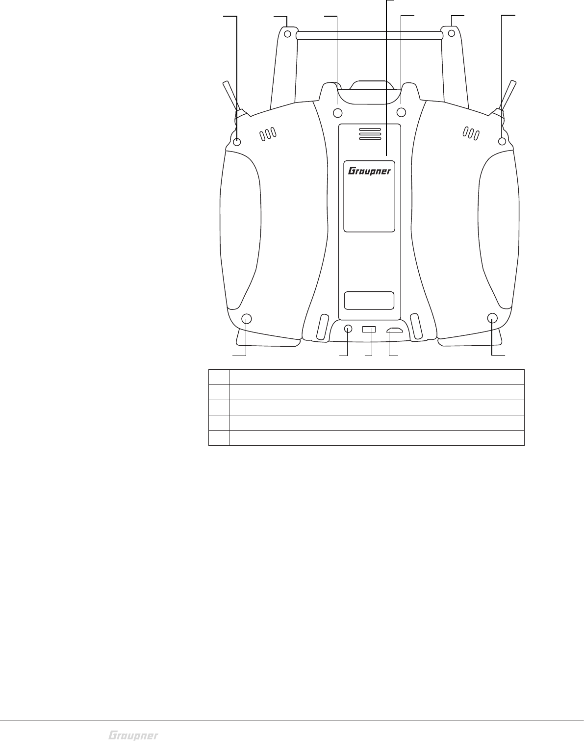
1 Case screws
2 Battery case cover
3 3,5 mm jack to connect earphones or a DSC cable.
4 Data socket to connect a smart box and to update the transmitter
5 Micro USB port, charge port, update port, joystick function
mz-12PRO
11
11
1
1
11 3 4 51
2

13 / 28
S1002.PRO_jh_V1
Connections and fixtures
Attaching the transmitter neck-strap
On the upper side of the transmitter there is an eyelet which can be
used to hook a neck-strap.
Jack socket
The port for a 3,5 mm jack is located on the back of the transmitter.
Depending on the settings in the menu (OHRH or DSC) this interface
can be used as a earphone port or as a DSC cable port.
Ear phones port
Though this interface both acoustic signals and voice messages are
emitted.
The volume can be controlled by "Voice volume" and "Signal vol-
ume" in the general settings.
DSC connection
Through a DSC cable the port can serve to use the transmitter with
a simulator o to connect it with another one in Teacher/pupil mode.
Switch the DSC mode in the "General settings menu". In this way you
can change the base display too. Right in the display appears "DSC".
To ensure a correct DSC connection, observe the following:
1. Perform any necessary adaptations in the menu.
2. When using the transmitter with a flight simulator or during the
teacher-pupil operation, set the On/Off switch always on the "Off"
position. Connect one end of the DSC cable in the DSC port of the
transmitter.
3. Switch the transmitter on.
ATTENTION
When your transmitter is directly connected to a desktop computer
by a connecting cable (DSC cable) and/or a computer interface is
connected to your simulator, the transmitter may be destroyed
by electrostatic discharge. This type of connection should therefore
only be used if you protect yourself from electrostatic discharge
while operating the simulator by wearing a commercially available
grounding armband. Graupner therefore strongly recommends
only using wireless simulators.
Data socket
The lower pins are suitable for connection of a smart box or an exter-
nal bluetooth module.
Micro USB charging socket
For the function please see section "battery charging"
14 / 28 S1002.PRO_jh_V1
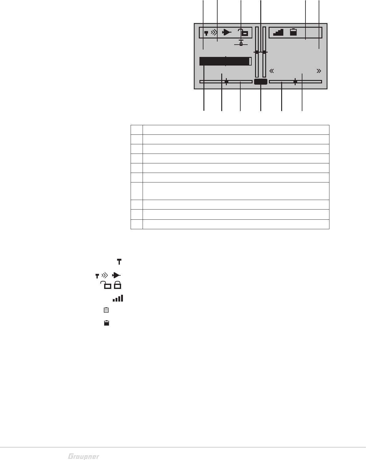
Display and touchpad
1 Model name
2 Memory 1 ... 250
3 Model type display (plane/heli, copter, car, boat)
4 Optical display of the trim position
5 Flight chronometer in min:s (forward/reverse)
6 Flight timer in min:s (forward/reverse)
7 Battery voltage (when a determined threshold is trespassed a warn
message is displayed, contemporary a warn signal is emitted).
8 Battery use timer since last charge in h:min
9 Display of the transmitter mode
10 Flight phases switching between flight phases through switch.
Symbols in the display
Symbols in the info list
No receiver in range
Display of the signal strength of the signal coming back from receiver
Button lock inactive / active
The active model memory is bound to a receiver
No connection to receiver
Current operating voltage of the receiver power supply with symbol
display of the power supply charge state
Display of the transmitter mode
NR: normal mode
TP: Teacher/pupil mode
M-01
1:23h
Stop
Flug
1:23
11:12
5.5V
5.4V
NR
5.1V
GRAUBELE
normal
123 4 56
7
8
494 10
0.0 V
5.2 V
15 / 28
S1002.PRO_jh_V1
Commissioning
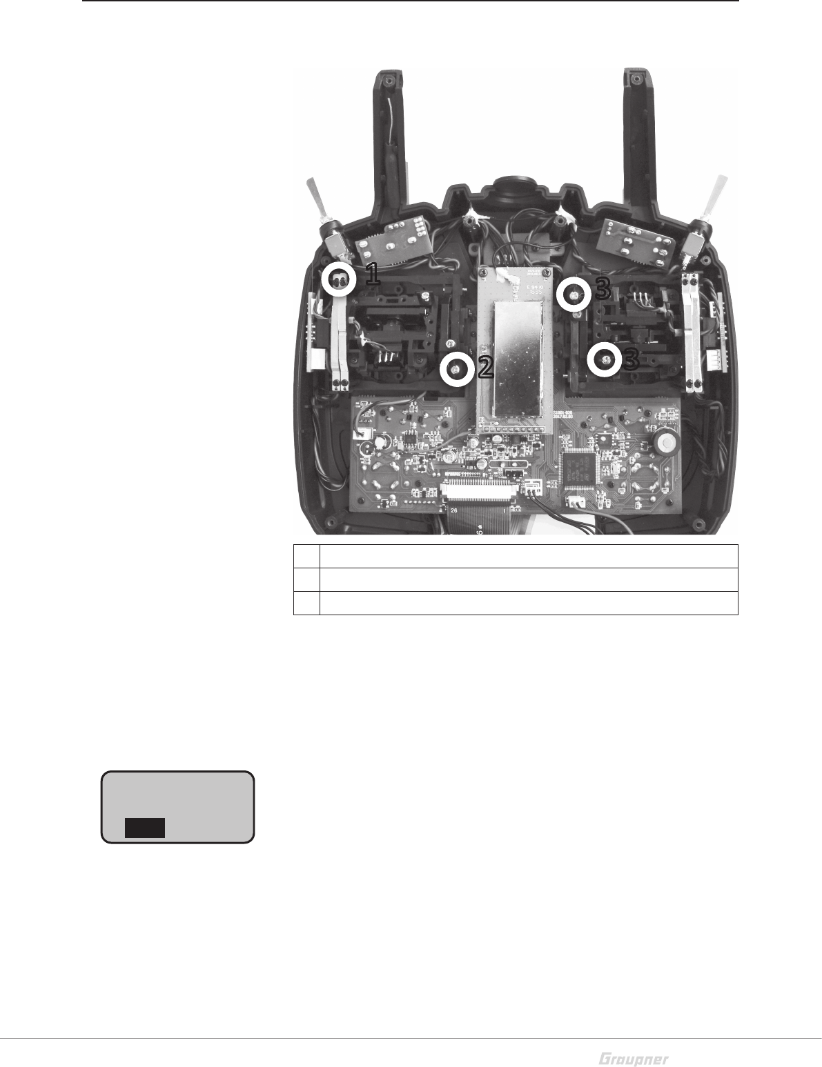
Settings by the first use
1 Adjusting screw of the brake spring for throttle/brake stick
2 Neutralizing screw
3 Stick self centering force adjust screws
Start display
After the transmitter is switched on by fixed wing of type "Motor on
C1 front/rear" the position of the output 1, so as in hely model the
output 6 connected servo, will be verified. If the related servo is out
of the idle position and because of the danger connected to a rotat-
ing motor, the RF module remains off for safety reasons.
In all other cases by switching on the transmitter the RF module will
be switched on too and in the center of the display it will appear the
message "RF ON/OFF".
You can wait until the message disappears automatically or you can
shorten the waiting time manually, by pushing the ENT button ()
of the right four-way button.
1
2
3
3
RF on/off?
OFF
ON
Please select
16 / 28 S1002.PRO_jh_V1
During this waiting time you can also switch the RF module off by
pushing the or button of the left four-way button which move
the black field, in this way the "ON" is shown normally and "OFF" is
inverted represented.
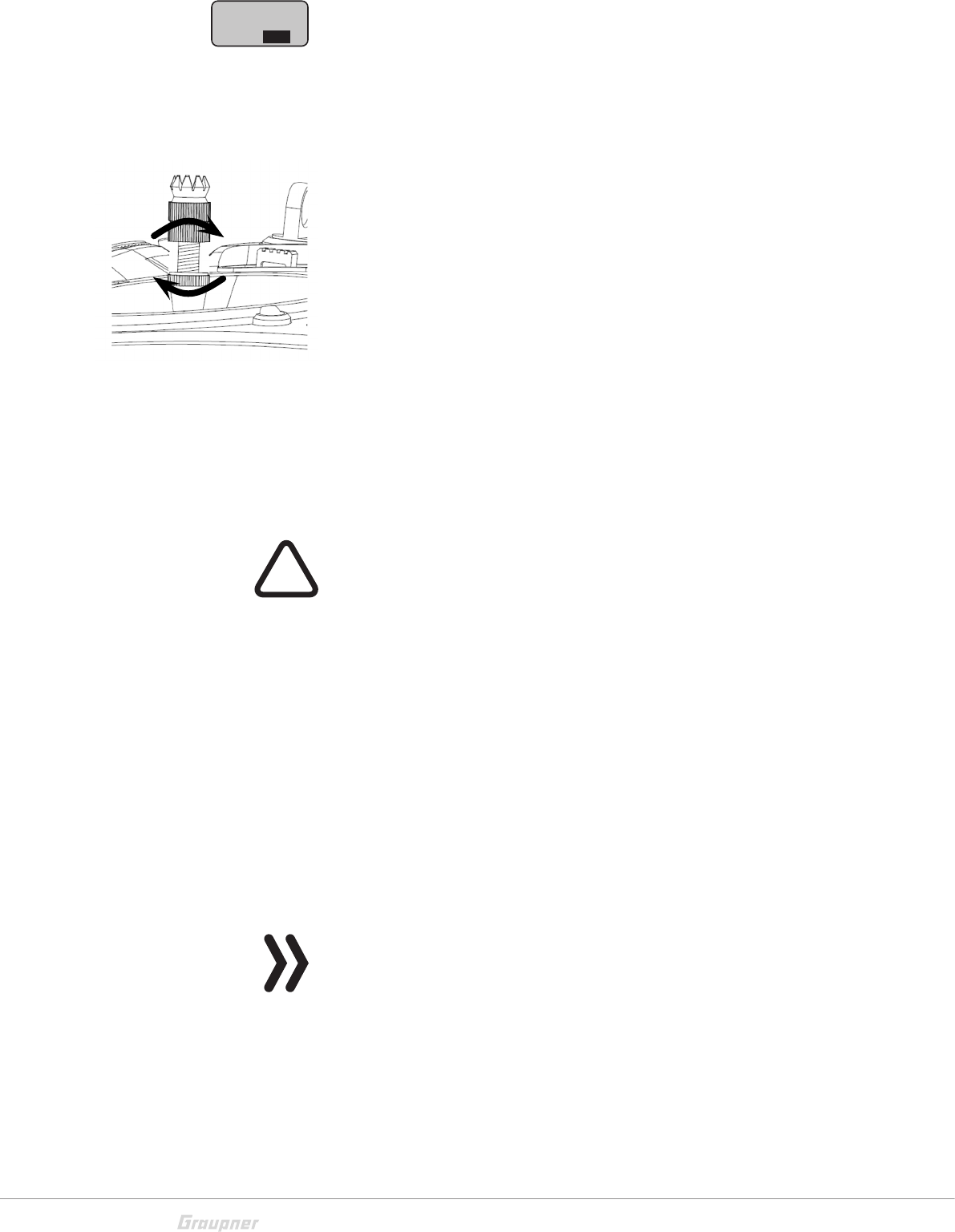
Control sticks length adjustment
Length of both control stick can be adjusted. Hold down the bottom
half of the knurled grip, and loosen the screwed connection by turn-
ing the top part:
You can now lengthen or shorten the control stick by screwing it up
or down. Then clamp the top and bottom part of the grip by rotat-
ing them against each other.
Opening/closing the transmitter housing
The transmitter should be opened only in the following cases:
If a self centering stick has to be converted in non self centering
If a non self centering stick has to be converted in self centering
To set the control stick centering force
CAUTION
Never switch the transmitter on while the housing is open! Risk of
short-circuit!
Open step by step:
Before opening the housing switch the transmitter off.
Open the battery case.
Remove the battery holder lifting it from one side, without forcing
it, release it from the velcro tape.
Unplug the connector.
Unscrew the eight screws with a crossscrewdriver.
Hold both housing halves with both hands and let the screws fall on
a proper surface turning the transmitter upside-down.
Rotate the lower half carefully and fold it to the bottom.
Note
Cables connect the lower half of the housing with the upper part
electronic components. This connection must not be damaged! Do
not touch the electronic boards.
RF on/off?
ON
Please select
OFF
!
17 / 28
S1002.PRO_jh_V1
Closing step by step:
Check if the upper and the lower part of the transmitter housing are
correctly coupled and the tiny cables are properly placed.
Screw the housing screws in their original position.
Connect the battery holder.
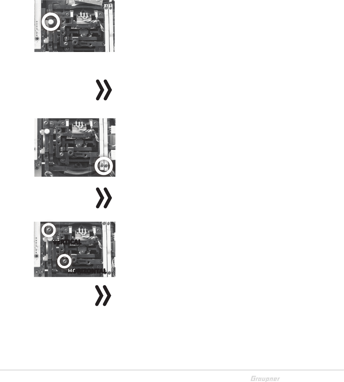
Neutralizing the control sticks
Both control sticks can be set from neutralizing to non-neutralizing.
Neutralizing step by step:
Locate in the left control stick gimbal the screw surrounded by a
white circle in the picture.
Turn the screw toward the inside of the transmitter until the relevant
control stick can move freely from stop to stop, or turn it outward
until the control stick resets itself independently.
Note
The right control stick gimbal is specular to the left one, so that here
the screw is located left under the middle.
Brake spring and ratchet
The outboard screw of the two marked in the figure adjust the brak-
ing force.
The inboard screw adjusts the strength of the ratchet for the respec-
tive control stick.
Note
The right control stick gimbal is specular to the left one, so that here
the screws are located right on the top side.
Control sticks centering force
The control sticks' restoring force can also be adjusted. The adjust-
ment is located next to the return springs.
By turning the respective adjust screw the spring force can be
adjusted.
Right turn = return harder
Left turn = return softer
Note
The right control stick gimbal is specular to the left one, so that here
the screws are located left in the middle.
VERTICAL
HORIZONTAL
VERTICAL
VERTICAL
HORIZONTAL
HORIZONTAL
18 / 28 S1002.PRO_jh_V1
General commissioning
Binding
The description of the binding process can be found in the Part
2 of the manual.
To use a transmitter you must associate a receiver to the transmitter.
This binding process is essential for the use of the model!
The precise binding process follow-up is described in the section
"Binding" of the Part 2 of the manual and in the related receiver
manual.
Note
The process is different for the various receiver types.
Binding-principle step by step:
1. Select the "main settings" menu in the transmitter
2. switch the RF module OFF
3. Connect the power supply to the receiver
... receiver with binding button:
• Push and hold the binding button at the receiver
• Start the binding process in your transmitter in the main settings
menu
... or receiver without binding button:
• The receiver is automatically in binding mode after switch on
• Start the binding process in your transmitter in the main settings
menu
4. If the binding process has been unsuccessful, repeat the process.
Transmitter power supply
The mz-12PRO HoTT transmitter is normally delivered with a
rechargeable battery.
Inserting the battery
Note
Pay attention when inserting the battery to the correct position and
make sure the contacts are solid.
Interruptions of the power supply to the transmitter during the use
of the models can lead to big danger for your self and for other peo-
ple.
Battery charging
Through the micro USB port you can charge the transmitter battery.
Use the included USB cable to connect the transmitter to a suitable
USB port and charge the transmitter battery. If the transmitter is
switched on the charge time is longer than if the transmitter is
switched off.
Model
memory
Wing
mix
M.Type
Phase
Servo
adjust.
Control
adjust.
D/R
Expo
Tx
adjust.
C1
curve
Stick mode 1
Timers 10:01
Rcv. Output
Bind –––
Range test 99s
C1
19 / 28
S1002.PRO_jh_V1
As soon as you connect the USB cable to the transmitter a selection
menu appears.. Here you can set up the function of the micro USB
port.
PC COM Port
Select this setting for updates with your PC.
Joystick
For use in a PC with a flight simulator. In this function the PC recog-
nizes the transmitter as a joystick. You can select the control area in
the "Base settings" menu in the line "USBjoistick". The control travel
can be set within 0 % and 100% or within -100% and +100%. The
standard setting for the most flight simulators is 0% to 100%.
Battery charging
Battery charge only, no data transmission
In the upper right corner this indication shows a countdown, this is
the time during which the indication is displayed. You can select
through the arrow keys up and down.
You have two charge possibilities:
1. Removing the battery from its case and charging it with a char-
ger
WARNING
The charger should always be supervised during charge and it
should be used only in rooms fitted with a smoke detector.
Removing transmitter battery
Remove the battery case cover. Then remove and disconnect the
battery plug by carefully pulling on the supply cable.
Charge the battery following the charger manual.
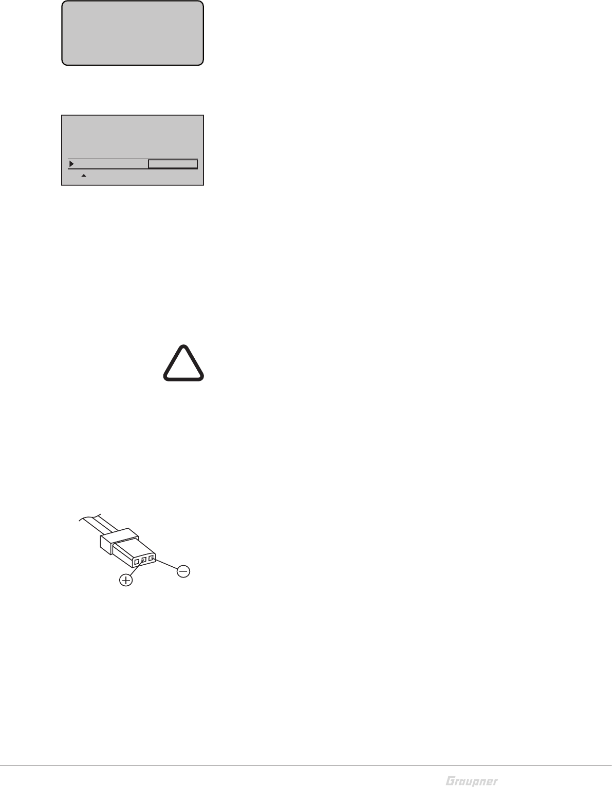
Inserting the transmitter battery
Connect the battery plug in the transmitter socket. Make sure that
the polarity is correct. Pay attention to the respective "+" and "-"
symbols near the socket.
Red= + Black/brown = -
Place the battery into its compartment and close the cover.
2. Through the USB port by charging with USB cable
The transmitter battery can be charged by the current supplied by
the USB port (5 V/max. 0.5 A). The charging process is shown through
the red lightning Graupner text. The indication quits when, with
switched off transmitter, the battery is full.
USB connected 7
PC COM Port
Joystick
Battery charge
3
Signal volume
Back port OHRH
DATA sel. Telemetry
DSC output PPM12
USBjoystick 0~100
!
20 / 28 S1002.PRO_jh_V1
Low voltage warning
The transmitter battery voltage should be monitored in the display
during operation. In case the voltage drops under a preset threshold,
standard setting 3,6 V, an acoustic warning signal is emitted and in
the display appears in a window "battery needs charging".
Now at the latest, the operation must be stopped and the transmit-
ter battery must be charged!
Battery use timer in the display
The battery use timer is shown in the lower left part of the display.
The battery use time is added at every use. After every charge the
timer is reset to "00:00". This happens only if the battery voltage
increases at least of 0,3V or if the battery is full.
Use and menu functions
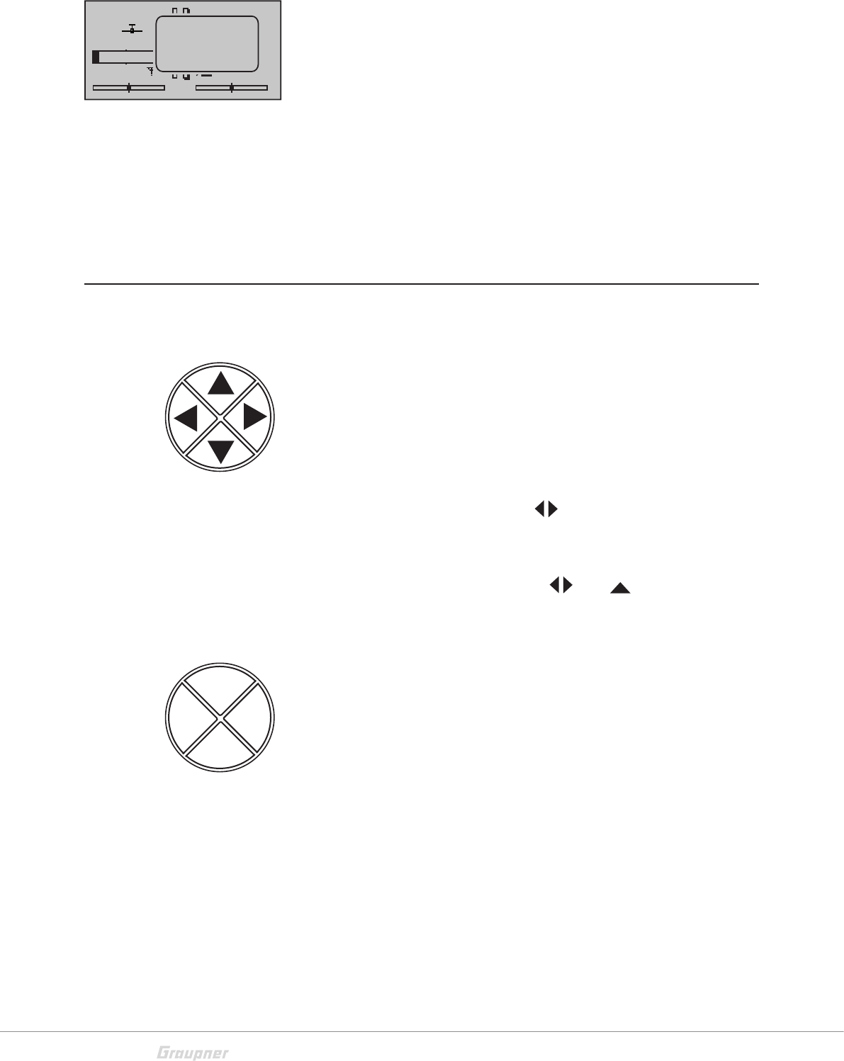
Four-way keys
Keys left of the display
Four-way keys (up, down, right, left)
By pushing one of these buttons in the base display the "Telemetry
data display" will appear.
By pushing the keys you can scroll the list according to the arrow
direction.
By simultaneous pushing the keys you can reset the value of an
already selected parameter which had been already modified
(CLEAR).
Pushing simultaneously the button and will cause a jump
from the transmitter's base screen or from almost any menu posi-
tion to the "Hidden mode" menu.
Keys to the left of the display
Four-way keys:
ENT button
Pushing the ENT key will cause a jump from the displayed base screen
which appears as soon as the transmitter is switched on to the
multi-function menu
By pushing the ENT key it is possible to accede to a previously selected
menu point.
Within the setting menu activate and deactivate or confirm by push-
ing the ENT key.
ESC button
Pressing the ESC button brings about a stepwise return to function
selection or back to the basic display. Any setting changed in the
meantime is retained.
GRAUBELE
#01
0:22h
S
Flug
«normal »
K78
0:00.0
0:00.0
0.0V
3.5V
Mx
x
HoTT
Batt. must
be re-
charged !!
ENT
VIEW
ESC
TLM

21 / 28
S1002.PRO_jh_V1
VIEW button
Pushing the four-way keys will cause a jump from the transmitter's
base screen or from almost any menu position to the "Servo display"
menu.
TLM button
Pushing the TLM key will cause a jump from the transmitter's base
screen or from almost any menu position to the telemetry menu.
Note
In the event the four way keys do not exhibit any functionality imme-
diately after switching the transmitter off and then on again right
away, this is not a fault. Just switch the transmitter off again then
wait for several seconds before switching it on again
Short-Cuts
CLEAR
Brief simultaneous touch of the keys of the left four way keys will
restore the active entry fi eld's changed parameter value back to its
default value.
"Servo screen"
Brief simultaneous activation of the VIEW key of the right four-way
keys will cause a jump from the transmitter's base screen or from
almost any menu position to the "Servo display" menu,
"Telemetry" menu
To recall the "Telemetry menu" from the base display of the trans-
mitter, push the TLM key of the right four-way keys.
To come back to the base menu push the ESC key.
Graphic display of telemetry data
Pushing one of the selection keys of the left four-way keys will
cause a jump from the base screen directly to the transmitter's
graphic display of telemetry data.
"HIDDEN MODE"
Pushing simultaneously the selection keys and of the four-way
keys will cause a jump from the transmitter's base screen or from
almost any menu position to the "Hidden mode" menu.
Key lock
The four-way keys can be locked by pushing simultaneously the TLM
and VIEW keys for about 1 second.
The key lock function is displayed by a lock symbol: The controls
remain operational. Push again the TLM and VIEW keys for about 1
second to remove the key lock.
22 / 28 S1002.PRO_jh_V1
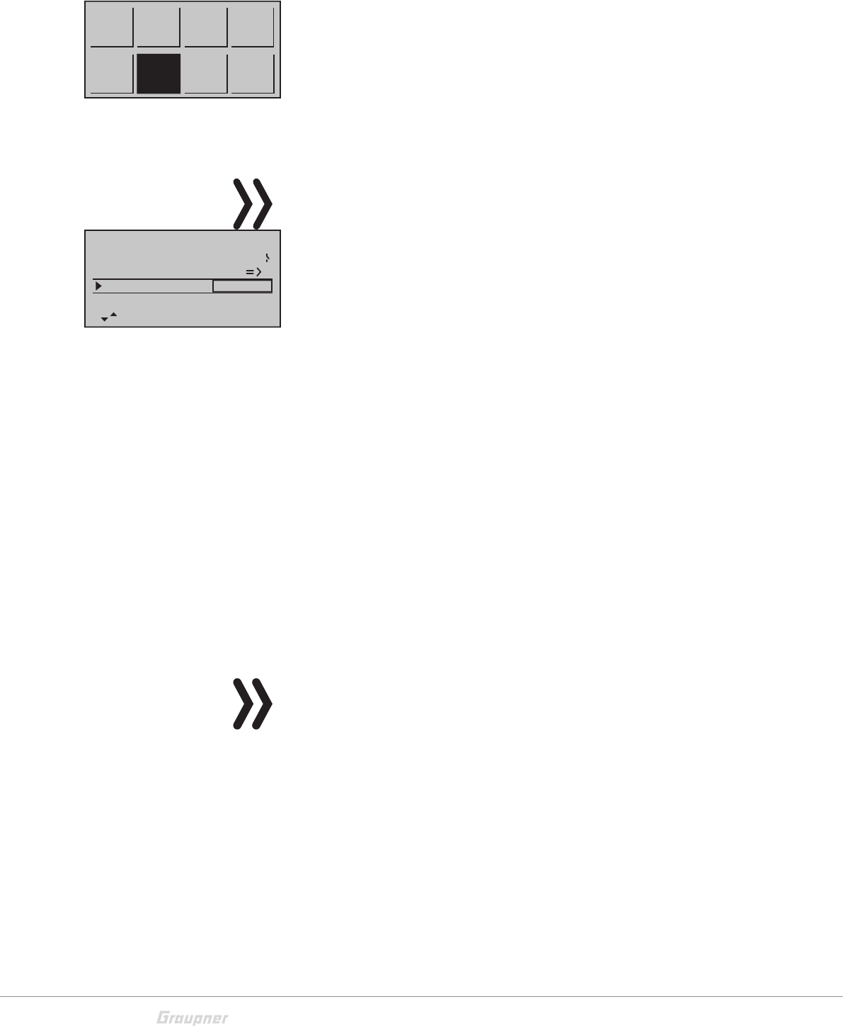
Function field in the display
Depending on the given menu, certain function fields will appear on
the bottom display line.
A marked function is activated by pushing the SET key.
Function field:
SET (SET) Setting
SEL (SELECT) Selection
STO (STORE) Store
SYM Set values symmetrically
ASY Set values asymmetrically
Switch symbol field
(assignment of all types of
switches)
Within a menu, change to the
Second page (menu continua-
tion)
Hidden mode
The menu "Hidden Mode" can be reached from almost any menu
position.
push and hold the left, the right and the lower keys of the left four-
way keys.
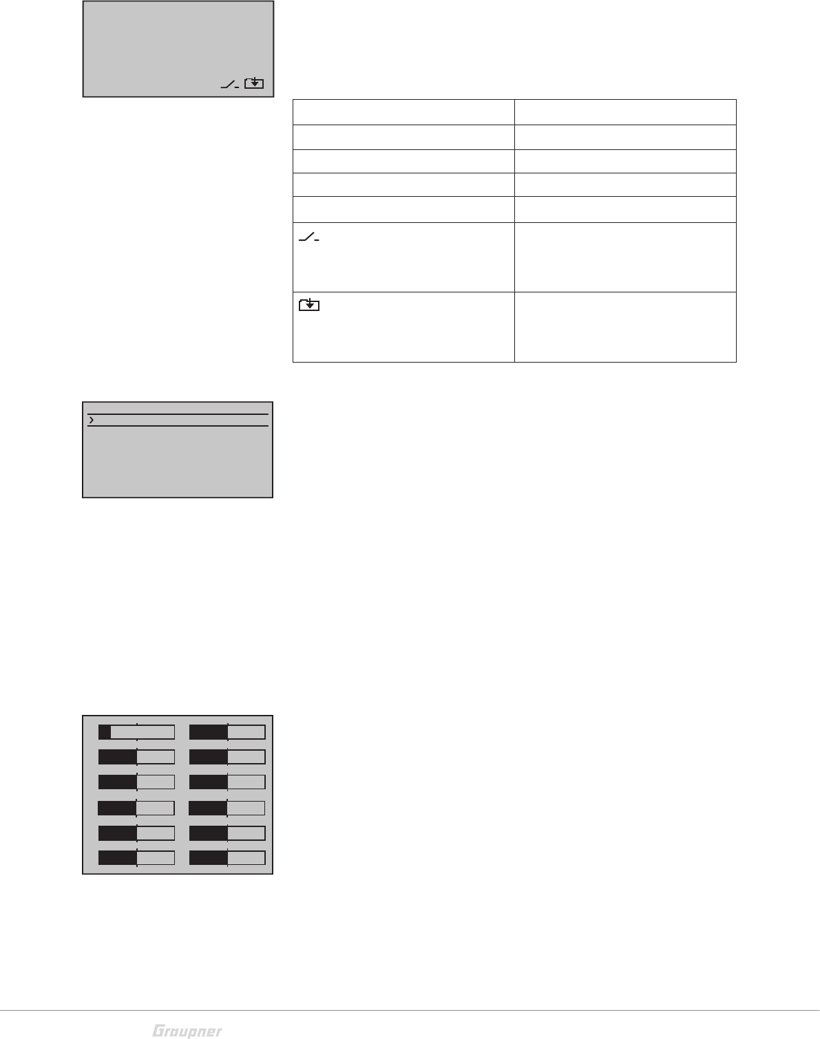
Stick calibration
If the center position of your self-neutralizing control stick does not
precisely correspond to 0% control travel, you can check and correct
it as follows.
Stick calibration step by step:
Move to the "Model memory" menu and initialize a free model
memory. Whether the model to be initialized is a winged aircraft or
a helicopter is irrelevant.
Move to the "Servo display" menu, pressing the VIEW key of the right
four-way keys, without any interim change to trim settings or other
program settings.
In this menu point you can check if your sticks are correctly centered.
Bring then all the sticks in the middle position. If the sticks are cor-
rectly placed, this display should ideally look like the one shown on
the left.
Otherwise the graph bars show current setting percentages for con-
trol stick control functions which are not self-neutralizing.
SET SEL STO SYM ASY
HIDDEN MODE
STICK CALIBRATION
1
3
5
2
4
6
0%
0%
0%
–100%
0%
0%
78
0%
0%
910
0%
0%
11 12
0%
0%
23 / 28
S1002.PRO_jh_V1
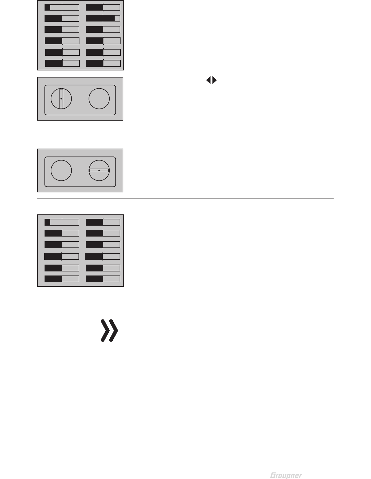
One after the other, put both sticks into each of their four possible
limit positions without exerting force at the limit position and check
if the value are between -100% and +100%.
If you note that the sticks do not reach the desired values, move to
the "Stick calibration" line in the "HIDDEN MODE" menu and push
the ENT key on the right four-way keys to confirm.
The flashing arrows indicate in which direction you have to push the
sticks.
With the selection keys of the left four-way keys allow you to
cyclically select the positions of the four calibrated sticks.
Move the stick to the end course of the indicated direction.
Confirm the calibration by pushing the ENT key.
Pushing the ESC key will terminate the process and return to the sub-
menu "Stick cali.".
Example: Bring here the respective left blinking selection arrow of
the right stick to the left limit. Tip on the SET key. So the calibration
of the right stick left limit. The circle in the middle of the stylized stick
blinks as confirmation.
Servo display
The optical display of the current servo position can be seen by push-
ing the VIEW key () of the right four-way keys from the base display
so as from almost every other menu positions.
The current setting of each servo is displayed precisely between
-150% and +150% of the normal path taking into account the control
and servo settings, dual rate/expo functions, the interaction between
the linear and curve mixes, etc.
0% equals the middle position of the servo.
You can therefore check your settings without having to turn on the
receiver.
Attention
You have however to carefully test all the program steps on the
model before first use to make sure there are no errors!
For normal fixed wing models, the display follows the assignment
below:
1
3
5
2
4
6
0%
0%
–100%
0%
0%
+100%
78
0%
0%
910
0%
0%
11 12
0%
0%
STICK CALIBRATION
CONTRAST
LANGUAGE
0
VOICE DEUTSCH
ENGLISH
STICK CALI.
0%
STICK CALIBRATION
CONTRAST
LANGUAGE
0
VOICE DEUTSCH
ENGLISH
STICK CALI.
+102%
1
3
5
2
4
6
0%
0%
0%
–100%
0%
0%
78
0%
0%
910
0%
0%
11 12
0%
0%
24 / 28 S1002.PRO_jh_V1
Bar 1 Throttle/brake servo or airbrake right
Bar 2 Aileron or left aileron
Bar 3 Elevator
Bar 4 Rudder
Bar 5 Aileron right / free channel
Bar 6 Flap (left) / free channel or 2nd elevator servo
For helicopter models, the display follows the assignment below:
Bar 1 Pitch or roll (2) or nick (2) servo
Bar 2 Roll (1) servo
Bar 3 Nick (1) servo
Bar 4 Yaw servo (gyro)
Bar 5 Gyro or Nick (2) Servo
Bar 6 Throttle servo or speed controller
Pushing the ESC key () of the right four-way keys you turn back to
the related output point.
Good to know!
Note that the servo display refers exclusively to the original sequence
of the servos, that is, it does not refer to any changes to the outputs
made in the "Transmitter settings" menu, or via telemetry in
the "Receiver output " submenu of the "Transmitter setting" menu.
Good to know!
The count of the channels displayed in this menu refers to the 12
control channels available in this transmitter mz-12PRO HoTT. The
number of usable channels depends on the type of receiver as well
as the number of connected servos and may therefore be signifi-
cantly less.The number of usable channels depends on the type of
receiver as well as the number of connected servos and may there-
fore be significantly less.

25 / 28
S1002.PRO_jh_V1
Firmware update
The programs and files which are also required for updating the
transmitter combined into one software package can be down-
loaded from www.graupner.de.
Download this software package from the Internet, and unpack it on
your computer. All other information can be found in internet in the
same page where the software package is available.
Firmware updates of the transmitter can be performed through the
micro USB port on the back side.
Note
Please note that compatible firmware is required for reliable
communication between the HoTT components. The programs
and files that are required to update are therefore combined into
a single file.
The current firmware version can be found on the Internet at
www.graupner.de.
Only operate your transmitter using the current software ver-
sion. these information can also be found at: www.graupner.de
=> Service & Support => Update and revision history for
GRAUPNER HoTT components.
Before each update, check the transmitter battery charge or
charge it as a precaution, and save all model memories with the
gr_studio program so that they can be restored if necessary.
Do not disconnect the link to the computer during an update!
Make sure that the link between the transmitter and computer
is operational.
After each update, check to make sure that the models function
correctly.
Transmitter software update
Connect your switched off transmitter with your PC, by using the
included USB cable, which is supplied with the package content, plug
USB cable directly to the micro USB port of the transmitter and the
other end to a free port in your computer.
Restoring the transmitter software
If a firmware update for the transmitter is unsuccessful or the trans-
mitter program freezes and the transmitter cannot be turned off
using the "POWER" switch, then remove the transmitter's battery
after setting the switch to "POWER = OFF" position, or pull the plug
from the transmitter battery. While making sure that the POWER
switch is in the "OFF" position, wait a few seconds and then turn on
the battery.
26 / 28 S1002.PRO_jh_V1
In this case as well, as described in the pages before, download a
current software package from the Internet and open it on your
computer or, if you have already done this, start the program gr_Stu-
dio, and follow the information in the section "Restoration" in the
instructions provided in the software package.
Declaration of conformity
S.1002.PRO - mz-12PRO HoTT
Graupner/SJ declares that the product is conform to EU norms.
EMV 2004/108/EC:
EN 301 489-1 V1.9.2
EN 301 489-17 V2.1.1
EN 62479:2010
LVD 2006/95/EC:
EN 60950-1 + A11 + A1 + A12 + A2:2013
R&TTE 1999/5/EC:
EN 300 328 V2.1.1
EN 62311:2008
27 / 28
S1002.PRO_jh_V1
Notes on environmental protection
Disposal notes
This symbol on the product, user manual or packaging indicates that
this product must not be disposed of with other household waste at
the end of its life. It must be handed over to the applicable collection
point for the recycling of electrical and electronic equipment.
The materials are recyclable as marked. By recycling, material reus-
ing or other forms of scrap usage you are making an important con-
tribution to environmental protection.
Batteries and accumulators must be removed from the device and
disposed of at an appropriate collection point. Please inquire if nec-
essary from the local authority for the appropriate disposal site.
Care and maintenance
Notes on care
The product does not need any maintenance. Always protect it
against dust, dirt and moisture.
Clean the product only with a dry cloth (do not use detergent!) lightly
rub.
Warranty
The Graupner, Henriettenstrassee 96, 73230 Kirchheim/Teck grants
from the date of purchase of this product for a period of 24 months.
The warranty applies only to the material or operational defects
already existing when you purchased the item. Damage due to mis-
use, wear, overloading, incorrect accessories or improper handling
are excluded from the guarantee. The legal rights and claims are not
affected by this guarantee. Please check exactly defects before a
claim or send the product, because we have to ask you to pay ship-
ping costs if the item is free from defects.
The present construction or user manual is for informational pur-
poses only and may be changed without prior notice. The current
version can be found on the Internet at www.graupner.de on the
relevant product page. In addition, the company Graupner/SJ has
no responsibility or liability for any errors or inaccuracies that may
appear in construction or operation manuals.
No liability can be accepted for printing errors.
P

FCC Statement
1. This device complies with Part 15 of the FCC Rules. Operation is
subject to the following two conditions:
(1) This device may not cause harmful interference.
(2) This device must accept any interference received, including
interference that may cause undesired operation.
2. Changes or modifications not expressly approved by the party
responsible for compliance could void the user‘s authority to operate
the equipment.
• NOTE
This equipment has been tested and found to comply with the limits for
a Class B digital device, pursuant to Part 15 of the FCC Rules.
These limits are designed to provide reasonable protection against
harmful interference in a residential installation. This equipment
generates uses and can radiate radio frequency energy and, if not
installed and used in accordance with the instructions, may cause
harmful interference to radio communications. However, there is no
guarantee that interference will not occur in a particular installation.
If this equipment does cause harmful interference to radio or television
reception, which can be determined by turning the equipment
off and on, the user is encouraged to try to correct the interference by
one or more of the following measures:
- Reorient or relocate the receiving antenna.
- Increase the separation between the equipment and receiver.
- _Connect the equipment into an outlet on a circuit different from that
to which the receiver is connected.
- Consult the dealer or an experienced radio/TV technician for help.