GRIDCOMM GC1338 Master Light Controller User Manual
gridComm Pte Ltd Master Light Controller Users Manual
GRIDCOMM >
Users Manual
PB050281602)GC1338-LR))
3-Phase)DIN)Rail)Master)Light)Controller)))))))))))))))))))))))))))))))))))))))))))))))))))))))))))))))))
Product)Brief)
© gridComm Pte. Ltd. Draft Product Brief Page 1 of 5
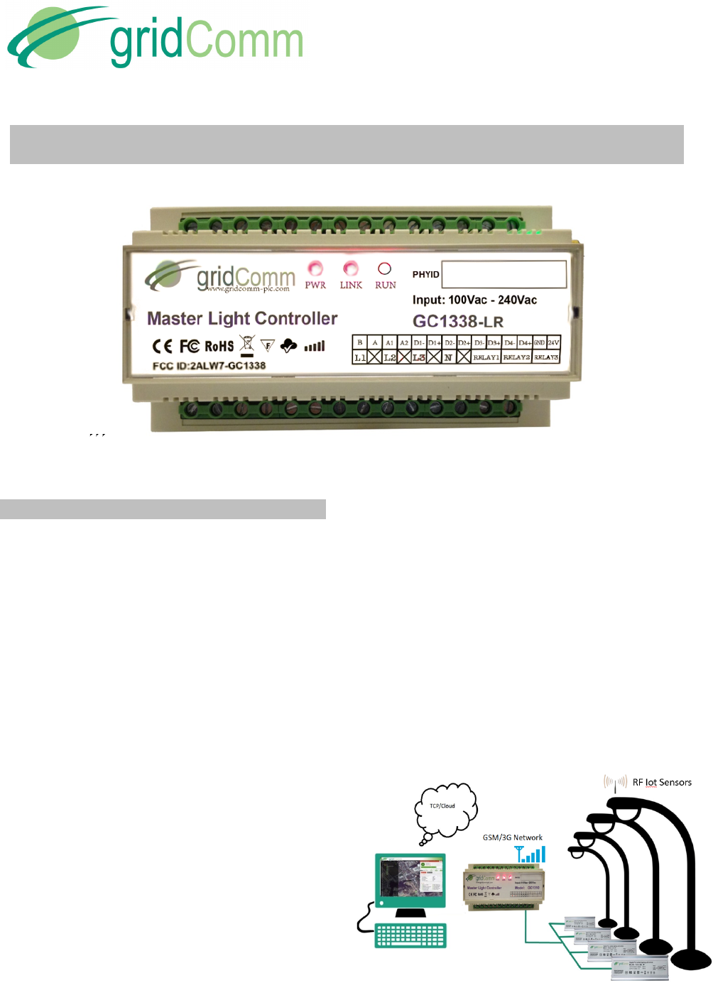
3-Phase DIN RAIL OFDMA Master Light Controller- GC1338
Figure'1-'GC1338'''3-phase'DIN'Rail'Master'Light'Controller'
Overview
The gridComm GC1338 is a 3-Phase DIN Rail Hybrid
Power Line Communication (PLC)- Radio Frequency
(RF) Master Light Controller designed for Street Light
Control operations. The gridComm Master Light
Controller (MLC) serves as a powerful concentrator and
gateway connecting a network of streetlights to the
cloud-based Street Light Management Software,
controlling and monitoring the operations of turning
on/off, dimming, scheduling, alarm events and data-
logging functions of an individual light or a group of street
lights.
The 3-phase DIN Rail Master Light Controller utilizes the
industry-leading gridComm GC2200 IC chip, an 18-
channel OFDMA (Orthogonal Frequency Division
Multiple Access) Power Line Communication
Transceiver. The 18 PLC channels are capable of
operating over a wide frequency range from 5KHz to
500KHz on the power lines whilst the 19th RF channel
operates on industrial-strength ISM frequency bands.
By taking advantage of its inherent 18 independent PLC
channels and the additional 19th RF channel, the
GC1338 can communicate over PLC and RF
concurrently. This brings upon the benefits of operating
in a single unified communication network using
common communication protocol, command sets and ID
addressing scheme.
With its sub-GHz RF option capability, the MLC can
communicate with plug-and-play RF battery-operated
IoT sensor nodes, such as environmental, light, pollution,
flood and proximity sensors, or any hybrid nodes which
leverage on GC-Net networking firmware using power
line network as the backbone network infrastructure. The
MLC also integrates Digital I/Os that could be connected
to an external anti-tamper or overload sensor for fail-safe
measures and motion sensors or other sensors based on
trigger events such as movements, light or sound. The
MLC is also equipped with Analog I/Os for analog signal
acquisitions from sensors such as temperature sensors,
humidity sensors, etc for further processing. In addition,
there is an on-board 4GB internal memory for storage of
historical data. The connectivity TCP link with the
backend Street Light Management Software (SLMS) is
enabled via the built-in 3G modem. The GC1338 can
automatically perform node discovery and establish
suitable repeaters to set up a robust routing network
based on a set of complex algorithms.
Figure 2 illustrates the implementation of a Smart Street
Lighting Sensor Network System using the GC1338 in
conjunction with gridComm’s Digital Power Supply (DPS)
and Street Lights Management Software.
Figure'2-'Smart'Street'Light'Sensor'Network'System
PB050281602)GC1338-LR)
3-Phase)DIN)Rail)Master)Light)Controller)))))))))))))))))))))))))))))))))))))))))))))))))))))))))))))))))
Product)Brief)
© gridComm Pte. Ltd. Product Brief Page 2 of 5
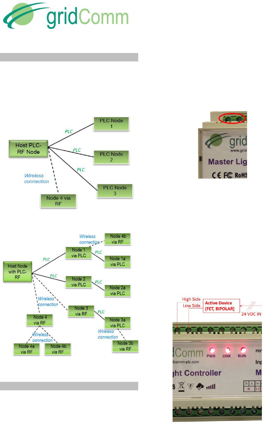
Auto Network Applications
The GC1338/1338 is optimized for network topologies
such as star or tree configurations. Figure 3 shows a
simple hybrid PLC-RF network system implemented
with GC1338 connected with four modems installed in a
“Star” configuration. Figure 4 shows a hybrid “Tree”
network (PLC/ wireless modes) with GC1338.
Figure'3-'“Star”-Shaped'Network'
Figure'4'-'Hybrid'“Tree”'Structure'
Features
Besides being a 3-Phase PLC concentrator, the
GC1338 also provides RS485 connections and a set of
Digital Inputs and Digital Outputs.
• RS485
The RS485 connection provides an easy way to
interface the Master Light Controller with a laptop or
PC for configurations or debugging. The RS485 can
also be extended to connect with any RS485 device
(eg. RS485-Ethernet or RS485 sensors) to enable a
feature or function.
Figure'5-'RS485)
• Digital Inputs
The GC1338 provides four groups of Digital Inputs,
D1+ and D1-, D2+ and D2-, D3+ and D3-, D4+ and D4-
as in Figure 6. These are a pair of optically isolated,
polarity-sensitive digital inputs that you can use to
monitor switch and sensor devices. D+, D- and a
24VDC Out can be used in conjunction with a sensor
with FET or BIPOLAR output for active devices. The
24VDC Out supplies a DC 24V@350mA for the sensor
while D+ and D- are connected to the sensor output of
the FET or BIPOLAR transistors. These Digital Inputs
can be configured to enable an event to be triggered
based on the conditions set. (Please contact
gridComm, for future use only)
Figure'6-'Digital'Inputs'of'GC1338'
PB050281602)GC1338-LR)
3-Phase)DIN)Rail)Master)Light)Controller)))))))))))))))))))))))))))))))))))))))))))))))))))))))))))))))))
Product)Brief)
© gridComm Pte. Ltd. Product Brief Page 3 of 5
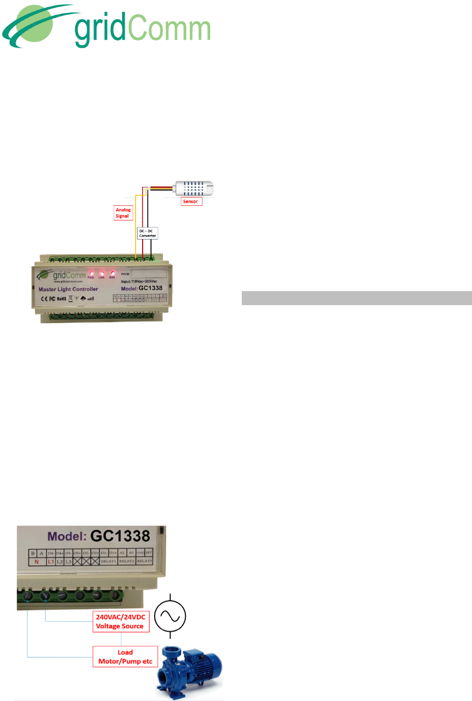
• Analog Inputs
A1 and A2 are terminals for analog signals input.
These terminals can be used for analog signals
acquired from sensors such as temperature sensors,
humidity sensors, etc for further processing. The
reference for A1 and A2 is GND. Figure 7 shows an
Analog input implementation.
Figure'7-'Analog'Inputs'of'GC1338'
• Relays
RELAY 1, RELAY 2 and RELAY 3 are three pairs of
high-voltage, high-current, single pole single throw
(SPST) relay outputs rated at 240VAC@10A or 24V
DC@10A. The SPST relay contacts are polarity-
insensitive, and they can be used to switch both AC
and DC loads. It can be used to perform on/off controls
on loads such as motors and lamps etc. as in Figure 8.
It can be configured to open the dry contacts based on
a schedule and/or when a combination of input
conditions occur, thus cutting off the power supply to
the load.. (Please contact gridComm, for future use
only).
Figure'8-'Dry'Contact'Relay'Control'
• 4GB On-Board Extended Flash Memory
The 4GB on-board extended flash memory (optional)
is important for storage of historical data such as
power consumption, device life time, alerts and
alarms. This historical data parameters can then be
easily retrieved by the system should there be a
failure with the TCP link or the server.
• GSM/3G TCP Link
The device is built in with a GSM/GPRS module to
enable the TCP link connectivity with the server
operating the Street Light Management Software.
Specifications
• Connects directly to 3-Phase Low-Voltage AC
power line with L1 (Phase A), L2 (Phase B) and
L3 (Phase C)
• Input power supply: L1, Neutral 100~240VAC
@100mA max, 50/60Hz.
• Surge protection: 3750V
• Maximum Power Consumption: < 8 Watts
• CPU: Cortex M3, 120 MHz
• Memory: 64MB flash memory; 64MB RAM
• Extended Flash Memory Support: up to 4GB
• Supports RS485 via a transparent protocol
• Pre-set Serial COM Port settings: 115200 Baud
rate, No Parity Bit, 8 Data Bit and 1 Stop Bit
• Supports MODBUS protocol when working in
conjunction with gridComm Street Light
Management Software
• Supports 3 sets of relays rated at 240VAC@10A
or 24V DC@10A
• Supports 4 sets of Digital Inputs. Sensors to the
digital inputs can be powered by the 24VDC with
appropriate DC-DC circuitry.
• Supports 2 sets of Analog Inputs. Sensors to the
Analog inputs can be powered by the 24VDC with
appropriate DC-DC circuitry.
• Built-In GSM/3G Modem Quad-Band 850/ 900/
1800/ 1900 MHz:

PB050281602)GC1338-LR)
3-Phase)DIN)Rail)Master)Light)Controller)))))))))))))))))))))))))))))))))))))))))))))))))))))))))))))))))
Product)Brief)
© gridComm Pte. Ltd. Product Brief Page 4 of 5
• GPRS multi-slot class 12
Output power
o UMTS 850/1900: 0.25W
o UMTS 900/2100: 0.25W
o GSM850/GSM900: 2W
o DCS1800/PCS1900: 1W
• HSPA+ Max. 14Mbps(DL), Max.
5.76Mbps(UL)
• WCDMA Max. 384Kbps(DL), Max.
384Kbps(UL)
• EDGE Class Max. 236.8Kbps(DL), Max.
118Kbps(UL)
• GPRS Max. 85.6Kbps(DL), Max.
42.8Kbps(UL)
• CSD GSM data rate 14.4Kbps, WCDMA data
rate 57.6Kbps
• Operating Temperature: -40 to 60℃
• Storage Temperature: -40 to 85℃
• Operating Humidity: 10 to 90% RH @ 60℃
• Storage Humidity: 5 to 90% RH @ 60℃
• Confirmed to comply with requirements set out in
The European Council Directive on Approximation
of the Laws of the Member States Relating to
RED (2014/53/EU) and RoHS (2011/65/EU). This
device passed the test which was performed
according to the following European standards:
o ETSI EN 300 220-1 V3.1.1
o ETSI EN 300 220-2 V3.1.1
o ETSI EN 301 489-1 V2.1.1
o ETSI EN 301 489-3 V2.1.1
o Manufacturer:
o Shenzhen Ju Yang Electronics Technology
Co. Ltd.
o Room 384, FuYong Information Building,
BaoAn District, ShenZhen City
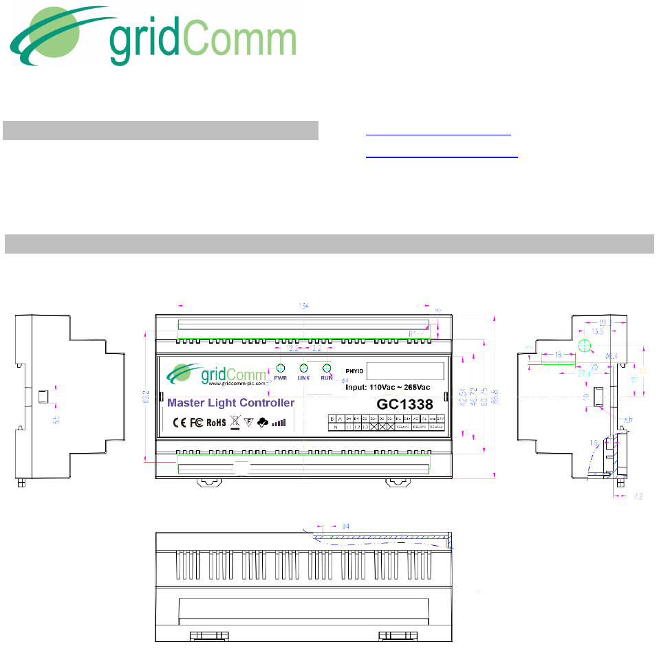
• Size in mm: 155 L x 110 W x 60 H Weight: 1000 g
• Flame Retardant ABS casing with DIN Rail
mounting
• PLC Specifications:
• 18 independent PLC channels operating with
up to 54 out of 100 pre-installed carrier
frequencies between 5 kHz to 500 kHz.
• 3QPSK, 3BPSK, or 1BPSK PLC modulation
schemes with up to 18 levels of redundancy
• PLC Raw data rates between 1.22 Kbps to
7.32 Kbps depending on power line conditions
• 32-bit PLC addressing scheme
• One PLC master node supports up to 240
PLC slave nodes (recommended to keep it about
100 nodes)
• Options for PLC operation on CENELEC A,
CENELEC B, CENELEC C, CENELEC D, FCC or
ARIB frequency bands.
• Support user packet size of up to maximum
of 512 bytes on PLC (user packets > 42 bytes will
be segmented into multiple standard data packets
automatically)
• PLC Distance: Up to 2km- the actual distance
depends on power line conditions such as noise,
attenuation and load impedance
• PLC Rx Sensitivity: -75 dBm
• LoRa Radio Frequency Module Specifications:
• LoRaTM Modem
• 168 dB maximum link budget
• +18 dBm - 60 mW constant RF output vs. V
supply
• +14 dBm high efficiency PA
• Data rate up to 2.4 kbps
• High sensitivity: down to -148 dBm
• Bullet-proof front end: IIP3 = -12.5 dBm
• Excellent blocking immunity
• Low RX current of 10.3 mA, 200 nA register
retention
• Fully integrated synthesizer with a resolution of
61 Hz
• FSK, GFSK, MSK, GMSK, LoRaTM and OOK
modulation
• Operating communication frequency available
in 433MHz or 868MHz or 915/923MHz
• Preamble detection
• 127 dB Dynamic Range RSSI
• Automatic RF Sense and CAD with ultra-fast
AFC.
• Packet engine up to 256 bytes with CRC.
PB050281602)GC1338-LR)
3-Phase)DIN)Rail)Master)Light)Controller)))))))))))))))))))))))))))))))))))))))))))))))))))))))))))))))))
Product)Brief)
© gridComm Pte. Ltd. Product Brief Page 5 of 5
Contact Information
For more information regarding the GC1338 3-phase
DIN Rail Master Light Controller including pricing and
ordering, please contact: gridComm Pte Ltd
www.gridComm-plc.com
sales@gridCommplc.com
Dimensions
Figure'9-'Dimensions'of'GC1338'
This device complies with part 15 of the FCC Rules. Operation is subject to the following two conditions: (1) this device may not cause
harmful interference, and (2) this device must accept any interference received, including interference that may cause undesired
operation.
The manufacturer is not responsible for ANY interference, for example RADIO or TV interference, caused by unauthorized
modifications to this equipment. Such modifications could void the user’s authority to operate the equipment.
The antenna(s) used for this transmitter must not be co‐located or operating in conjunction with any other antenna or transmitter.
This equipment has been tested and found to comply with the limits for a Class B digital device, pursuant to Part 15 of the FCC Rules.
These limits are designed to provide reasonable protection against harmful interference in a residential installation.
This equipment generates, uses and can radiate radio frequency energy and, if not installed and used in accordance with the
instructions, may cause harmful interference to radio communications.
However, there is no guarantee that interference will not occur in a particular installation. If this equipment does cause harmful
interference to radio or television reception, which can be determined by turning the equipment off and on, the user is encouraged to
try to correct the interference by one or more of the following measures:
‐‐ Reorient or relocate the receiving antenna.
‐‐ Increase the separation between the equipment and receiver.
‐‐ Connect the equipment into an outlet on a circuit different from that to which the receiver is connected.
‐‐ Consult the dealer or an experienced radio/TV technician for help.
FCC Compliance Statement