GROWATT NEW ENERGY SHINELANBOX ShineLanBox User Manual
SHENZHEN GROWATT NEW ENERGY TECHNOLOGY CO., LTD. ShineLanBox
User Manual
Growatt ShineLink
Quick Installation Guideline
For more info, please download from http://server.growatt.com
+86 755 2951 5888 +86 755 2747 2131
service@ginverter.com www.ginverter.com
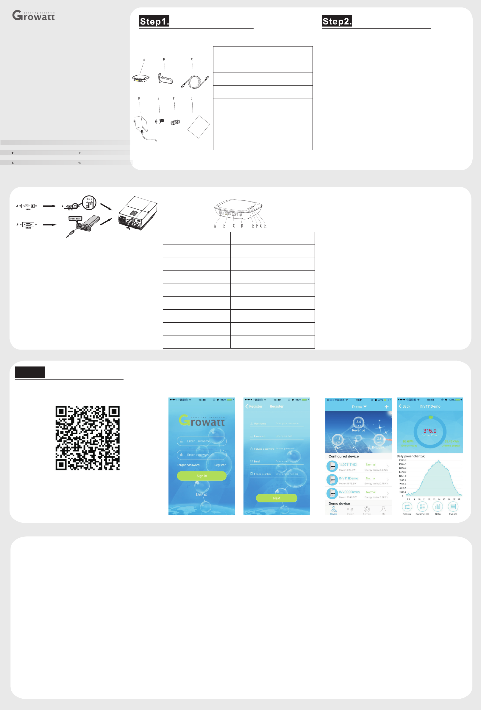
Unpacking, and check the package device list:
Unpacking
Item
Name
Quantity
A
ShineLanBox
1
B
ShineRFStick
1
C
Network
1
D
Power adapter
1
E
Fixing screws
4
F
Wall plastic posts
2
G
User manual
1
A If the RS-232 port of the inverter likes the
specification A as below, please turn on pin 1 of the
DIP switch, then plug the Growatt ShineRFStick to
the inverter directly via the RS-232 port and lock the
screws;
B If the RS-232 port of the inverter likes the
specification B as below, please poke the rubber plug
in the waterproof cushion of the Growatt
ShineRFStick, then plug the ShineRFStick to the
inverter via the RS-232 port and lock the screws.
Take the waterproof plate down from RS-232 port of
the inverter
C Power on the inverter, observe the blue led in the
ShineRFStick, if the led on and then turn to flash, it
means ok, otherwise means you should check the
installation.
Blue LED status:
Solid on: device is initializing
Solid off: no device found on RS232 port
Flashing fast (change every 0.2s): Found device on
RS232 port
Flashing slow (change every 1s): network
communication normally
Electrical Connection
1> ShineRFStick Electrical Connection
2> ShineLanBox Electrical Connection Connect the RJ45 interface of the ShineLanBox to the
router ,then plug in the power adapter to power on the
ShineLanBox.
After power on, the Power LED on, Network LED
flashing, then the ShineLanBox start to search the RF
device and connect to the server. Network LED on
means connect to the server ok, device LED flashing
means devices connect ok. If there are more than one
RF device, please note the device LED continuous
flashing times, it means the connected devices number.
Search “ShinePhone” in google play or app store, or scan the
picture below, download and install the app.
1.Run ShinePhone, please register a new user if is the first time.
When entering SN ,Please enter the ShineLanBox SN , not the
ShineRFStick SN.
Use ShineLink
Step3.
Note:
1.Power LED : connecting the power
2.Network LED : connecting the network
3.Device LED the number of the LED continuous
flashing means the device number connected to the
ShineLanBox
4.Configuration LED flashing when
configuration , if successful , the LED will be off.
:
:
2.Input the user name and password to log in.
Item
Name
Description
A
Power input
Connect to the power adapter
B
RS 485
Reserved
C
RJ 45
Connect to the network
D
Key
Function key
E
Configuration LED
Configuration the device
F
Device LED
Device number connected
G
Network LED
Connecting the network
H
Power LED
Connecting the power
3.Into the device page, check the device number configured
and the status.
4.Put the device list to the detail page, check the device
parameters.
Append
Short press the button of the ShineRFStick and
ShineLanBox , entering the configuration mode, if
successful, the configuration LED of the
ShineLanBox will be off ,and the blue LED of the
ShineRFStick will flash slowly.
Note:
1.Pressing the button of the ShineLanBox for more
than 6 seconds until the four LED flash will clear the
configuration information .
2.About the distance between the ShineLanBox and
the ShineRFStick, the maximum linear distance is
200m if there is no obstructions between then; the
maximum distance is 50m if there is one wall between
then; the maximum distance is 20m if there are two
walls between then.
NOTE: 1.Be sure to install the latest version of the software;
2.For more details, please refer to the content on
http://server.growatt.com .
【Android& 】iOS
Add new ShineRFStick:
This device complies with part 15 of the FCC Rules.
Operation is subject to the following two conditions:
(1) This device may not cause harmful interference,
and
(2) this device must accept any interference received,
including interference that maycause undesired
operation.
NOTE: This equipment has been tested and found to
comply with the limits for a Class B digital device,
pursuant to Part 15 of the FCC Rules. These limits are
designed to provide reasonable protection against
harmful interference in a residential installation.
This equipment generates, uses and can radiate radio
frequency energy and, if not installed and used in
accordance with the instructions, may cause harmful
interference to radio communications. However, there
is no guarantee that interference will not.
Occur in a particular installation. If this equipment
does cause harmful interference to radio or television
reception, which can be determined by turning the
equipment off and on, the user is encouraged to try to
correct the interference by one or more of the following
measures:
-- Reorient or relocate the receiving antenna.
-- Increase the separation between the equipment and
receiver.
-- Connect the equipment into an outlet on a circuit
different from that to which the receiver is connected.
-- Consult the dealer or an experienced radio/TV
technician for help.
Note: The manufacturer is not responsible for any radio
or TV interference caused by unauthorized
modifications to this equipment.
such modifications could void the user’s authority to
operate this equipment
Changes or modifications not expressly approved by
the party responsible for compliance could void the
user's authority to operate the equipment.