GROWATT NEW ENERGY ZIGBEE ZigBee WL-ZB User Manual ZigBee Module 2013 04
SHENZHEN GROWATT NEW ENERGY TECHNOLOGY CO., LTD. ZigBee WL-ZB ZigBee Module 2013 04
User manual
ZigBee Module
User manual

CONTENT
User Manual Information
1
Description
2
Setting the ZigBee ID and Channel of the Data Logger
3
Setting the ZigBee Module
4
Installation of ZigBee Module
5
FAQ
6
Technical Data
7
Contact
8
1 User Manual Information
1.1 Copyright Statement
Copyright © 2012 Shenzhen Growatt New Energy Co,.Ltd, hereinafter referred to as
‘Growatt’. All right reserved. No part of this document may be reproduced, stored in
a retrieval system, or transmitted, in any form or by any means, electronic,
mechanical, photographic, magnetic or otherwise, without the prior written
permission of Growatt New Energy. All infringement reserved.
Copyright No. is G1.0. Growatt reserved the final right of interpretation of this
manual. The product parameters, appearances and packages are subject to change
without notice. Readers are cautioned, however, that Growatt reserves the right to
make changes without notice and shall not be responsible for any damages,
including indirect, incidental or consequential damages, caused by reliance on the
material presented.
Distinguished users, thank you very much for your trust in our ZigBee Module
product, which is developed and manufactured by our R&D department. We sincerely
hope it can satisfy your need, also, we’re glad to receive your suggestions on
improving our product. The target of the manual is to provide the detailed product
information, installation, operation and maintenance.
1.2 About Manual
The user manual is applied for technicians and common users to operate and
maintain the ZigBee Module. The readers should be acquainted with some computer
network knowledge and operating skill.
1.3 Target Group
1
Before using the ZigBee Module, please read the manual carefully. In the meantime,
please keep it well, lest maintenance staff may not find it later. All the content,
pictures, logos, symbols are reserved. No part of this document may be transmitted in
any form without the prior written permission of our internal staff. The content of
manual could be changed. Every attempt has been made to make this document
complete, accurate and up-to-date. If there are any differences between the
contents of the instruction and the product, please regard the actual one as the
truth. You can download the newest version from our website www.growatt.com .
1.4 Guideline
2
1.5 FCC Warning
This device complies with Part 15 of the FCC Rules. Operation is subject to the
following two conditions:
(1) This device may not cause harmful interference.
(2) This device must accept any interference received, including interference that
may cause undesired operation.
Changes or modifications not expressly approved by the party responsible for
compliance could void the user's authority to operate the equipment.
NOTE: This equipment has been tested and found to comply with the limits for a
Class B digital device, pursuant to Part 15 of the FCC Rules. These limits are designed
to provide reasonable protection against harmful interference in a residential
installation. This equipment generates, uses and can radiate radio frequency energy,
and, if not installed and used in accordance with the instructions, may cause harmful
interference to radio communications. However, there is no guarantee that
interference will not occur in a particular installation. If this equipment does cause
harmful interference to radio or television reception, which can be determined by
turning the equipment off and on, the user is encouraged to try to correct the
interference by one or more of the following measures:
-- Reorient or relocate the receiving antenna.
-- Increase the separation between the equipment and receiver.
-- Connect the equipment into an outlet on a circuit different from that to which the
receiver is connected.
-- Consult the dealer or an experienced radio/TV technician for help.
RF Exposure Statement
To maintain compliance with FCC’s RF Exposure guidelines, this equipment should be
installed and operated with minimum distance 20cm between the radiator and your
body: Use only the supplied antenna.
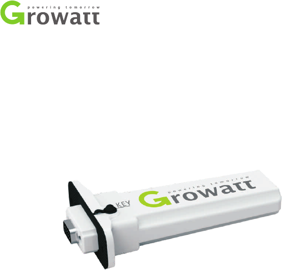
2 Description
ZigBee Module is a wireless device used to enable the communication between
inverter and data logger. The Shine Webbox and Shine Pano serve as the data logger.
3
3 Setting the ZigBee ID and Channel of
the Data Logger
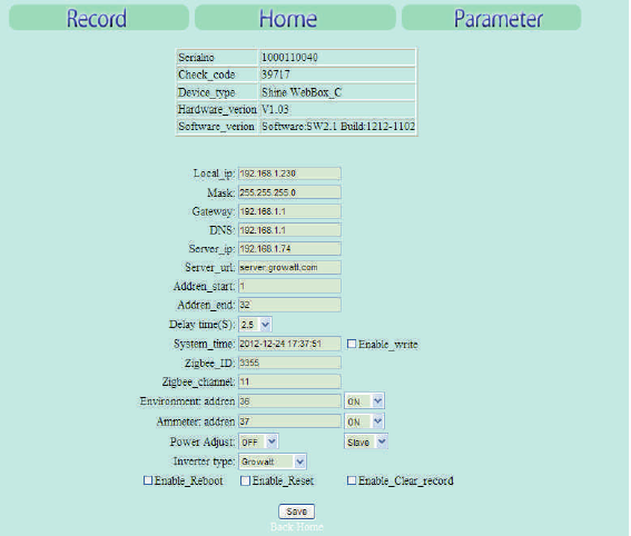
In order to adopt the ZigBee wireless communication method, the ZigBee ID and
Channel of the data logger should be configured first. Start the web browser and
enter 192.168.1.230 in the address bar, then you can set the ZigBee ID and Channel
via the integrated server of the data logger.
4
Note:
network segment, then it is available to get access into the integrated server of the
data logger. As to more details, please refer to the user manual of data logger e.g.
Shine Webbox User Manual.
Only the IP address of the data logger and the accessing PC are in the same

5
1. Set ZigBee ID. In “parameter” field, select “Zigbee_ID”, enter ZigBee ID within the
range between 1000 and 9999.
2. Set ZigBee channel. In “parameter” field, select “Zigbee_channel”, enter the
ZigBee channel within the range between 11 and 25.
3. If the parameters of data logger about the ZigBee configuration have been
modified, the parameters of the ZigBee Module have to be also modified.
4 Setting the ZigBee Module
6
1. Copy the folder “V53E Setup” from the CD to personal computer. Double click
“V53E Setup” → “Support” “ZConfigureV53E.exe”.
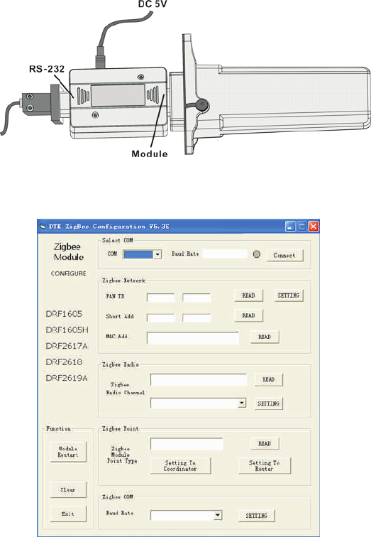
2. Connect the ZigBee Module with PC via the configuration Box. ZigBee Module
corresponds to the side of Configuration Box printed with “Module”, and the RS232
port corresponds to another side of Configuration Box printed with “RS-232”.
→
3. Operate the “ZConfigureV53E.exe”, as following figure.
7
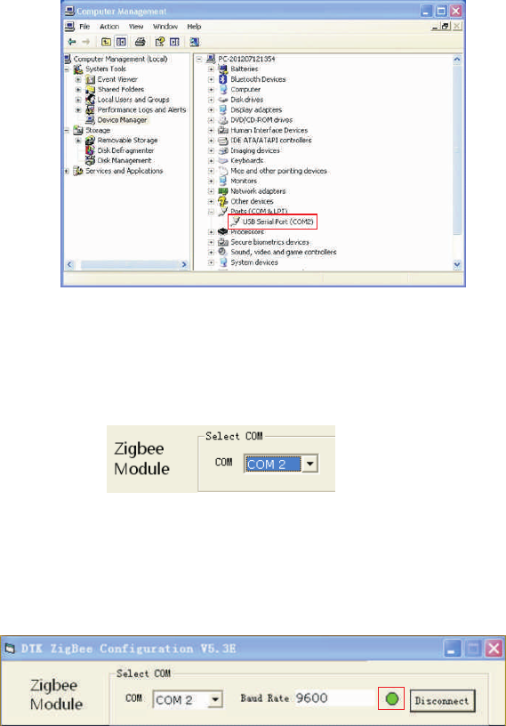
4. Right click “My computer” → choose “Manage” “Device Manager”
“Ports (COM & LPT)”.
→ →
5. Choose the same “COM port” with device manager.
6. Single-click “connect”. If the indicator light turns to green, the connection state is OK.
COM Port
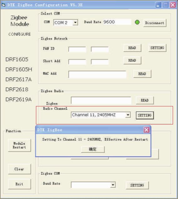
7. Select Zigbee Radio Channel. The range of channel is 11-25. The Radio Channel of
ZigBee Module shoud be set as the same value of “Zigbee_channel” configured in
the data logger.
8
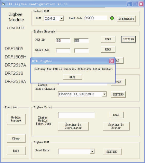
8. Set PAN ID. The “PAN ID” of ZigBee Module should be same as the “Zigbee_ID”
configured in the data logger. If not, the connection would fail. Enter two values in
the input box of PAN ID (e.g. 33 55). Single-click “SETTING”, then click “READ”. If it
works, the success dialog box will pop up. If not, please set again.
9
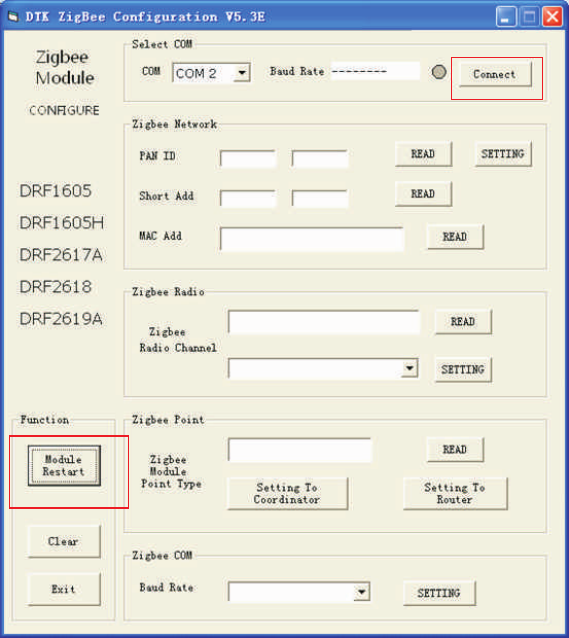
9. After setting, click on “Module Restart”, and then click on “connect”. If PAN ID is
still the pre-set value, the configuration is OK. If not, please set again.
Note: If you have already set 6 ZigBee Modules, one of the 6 Modules should be
power-on, and then you can set another 6 ZigBee Modules.
10
(1)
(2)
5 Installation of ZigBee Module
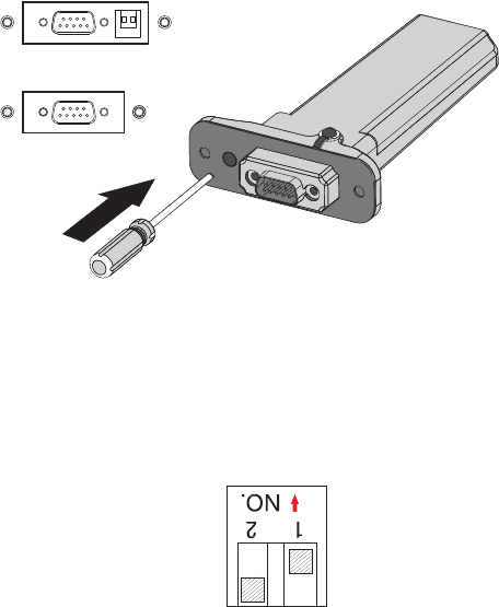
1. Plug the ZigBee Module to inverter via Rs232.
The RS232 port of Growatt inverter has two specifications.
If the RS232 port is compliant with the specification (1), please turn on the DIP
switch, then plug the ZigBee Module to the inverter directly via the RS232 and lock
screw.
RS-232
(1)
(2)
RS-232
11
If the RS232 port is compliant with the specification (2), please pry open the rubber
plug in the waterproof cushion, then plug the ZigBee Module to the inverter and lock
screw.
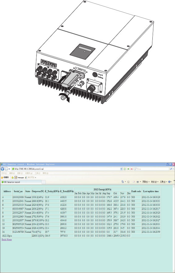
2. Open the “Record” interface of the data logger. If the inverter corresponding to
the ZigBee Module has shown in the list, the installation is OK.
12
1. When set PAN ID, if the dialog box displays “Setting New PAN ID Failed”, the
setting fails. Please click on “Module Restart” →“Connect”, and then reset PAN ID
(refer to chapter4, step 3-7).
2. When read PAN ID, if the value box displays “FF FE”, the setting fails. Please click
on “Module Restart” → “Connect”, and then reset PAN ID (refer to chapter4, step 3-
7).As an alternative method, you could change the value of the PAN ID and channel,
then reset the data logger and ZigBee Module.
3. As to the same one inverter, either wireless method or wired method could be
chosen as a monitoring scheme. If not, the data logger couldn’t search inverters well.
6 FAQ
13

7 Technical Data
Communication
Inverter
Protocol
Communication range
RS 232
Modbus RTU
300m (without obstacle)
Electrical Data
Voltage
Power consumption
8V-15V DC
<0.5W
Operating Conditions
Ambient temperature
Humidity
Degree of protection
- 20-60℃
5% --95%
IP65
General Data
Length*Width*depth
Net Weight
135*79*29mm
63g
14
8 Contact
If you have technical problems concerning our products, please contact Growatt.
Growatt New Energy Technology Co., Ltd
Building B, Jiayu Industrial Zone, #28 Guanghui Road, Longteng Community,
Shiyan, Baoan District, Shenzhen, P.R.China.
+86 755 27471942
service@ginverter.com
www.growatt.com
15
GR - UM - 011 - 01