GRT TECH LCNM-001 Local Control Node Module User Manual
GRT TECH CO., LTD. Local Control Node Module
GRT TECH >
RV1 -User Manual
User Manual of Local Control Node Module (LCNM-001)
1. Product description:
The Local Control Node Module (LCNM-001) uses Zigbee wireless control
method and protocol ( IEEE.802.15.4) as Wireless Intelligent Street Light control
System to control LED lamps on/off and to detect Street light function, to achieve
the effective energy-conservation and reciprocate state of LED light immediately.
Specification:
Input Voltage: 12~ 60Vdc
Max operated Current:20mA
Power consumption:< 1W
Environmental temperature:-40 ~ 85℃
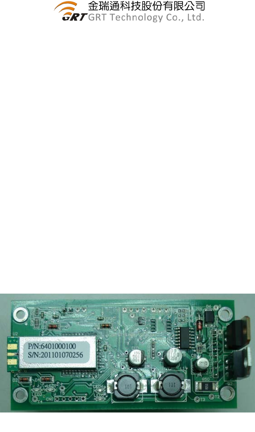
2. Appearance:
PCB Dimension: 95mm (Length) ; 45mm (Wide)
Please refer to the photo (A) and (B)
IRF540
TIP41C
U-POWER1000D
Photo (A) : Front view of PCB
2
2.1 Key Components:
UBEC zigbee module U-POWER1000D
Microchip MCU PIC18F26K20
AnaChip step-down DC/DC converter
Fairchild MOS HEF40106BT
VISHAY MOSFET IRF540
STMicroelectronics Amplifier LM324DT
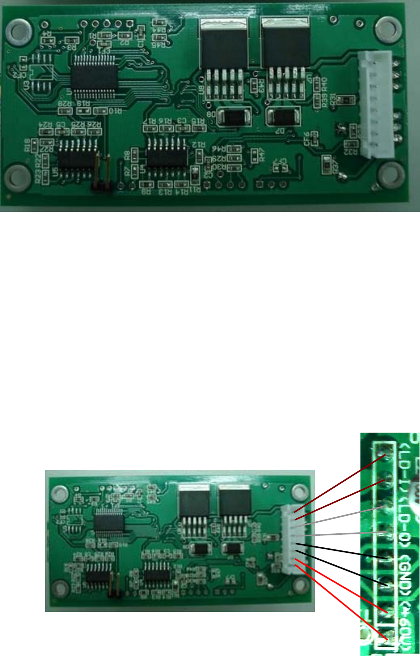
2.2 Interface description:
(1) Pin (+60V):connected to power supply positive voltage.
(2) Pin (GND):connected to power supply negative voltage.
(3) Pin (LD-O):load output pin is same as GND pin.
(4) Pin (LD-I):Load input pin.
Photo (B) : Back view of PCB
Photo (C) : Interface description
3
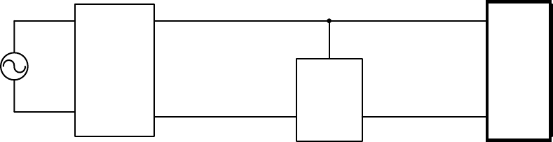
3. The Configuration of LCN Module and illustration of street LED lamp
installation
85~240V
Vout[+]
LED[-]
Lamp
Power
Supply LED燈
LCN
AC
LED[+]
Vout[-] (LD-O)
(GND) (LD-I)
(+60V)
The DC power of LCN module is via Lamp power supply Voltage output(+) 60V ,
and parallel connected with LED Lamp.
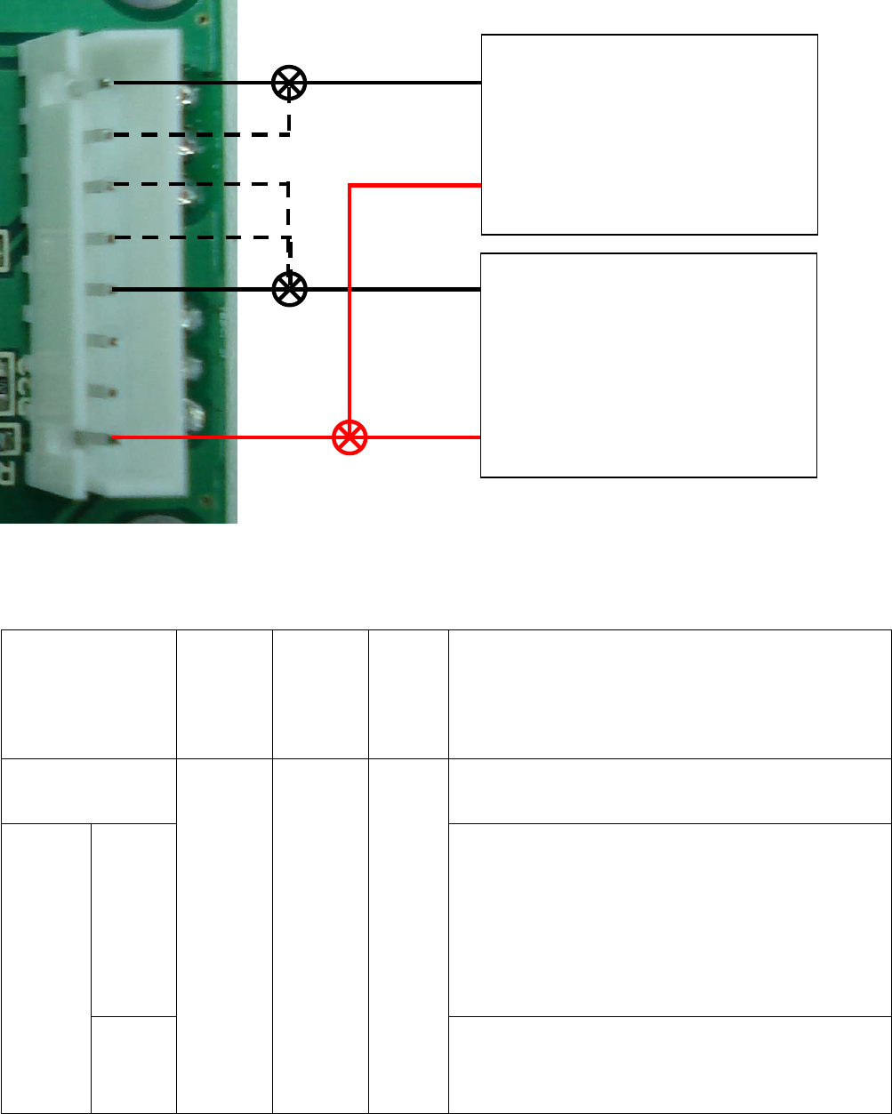
+60V:on LCN there are 2 pins connected together
GND Pin: There are 2 GND pins connected to ”Vout[-] of Lamp Power Supply.
LD-I: Two pins of LD-I shall be connected to negative (”LED[-]) of LED lamp,
due to large current flow will pass through this conductor, therefore shall
pay more attention to the wire gage connecting to these pins.
LD-O: These 2 I/O pins are parallel connected to ”Vout[-]”of Lamp Power
Supply,
The load current of LED lamp will flow through this path, shall be careful
the wire gage is sufficient for large load current.
LED
Lamp
4
4. Application Scope
Item
LED
Lamp
Current
LED
Power
consum
-ption
Output
Voltage Voltage difference between Load and Unload
Fixed Power
voltage ---
With
VR
control
1. The voltage difference less than <8V:OK
2. Adjust VR l to control voltage difference
<8V:OK
3.If adjust VR, Voltage difference between
Load and unload is still > 8V, is not
recommend to use.
Constant
Current
W
ithout
VR
control
<15A <150W
12V ~
60V
1. The voltage difference less than <8V:OK
2. If voltage >8V:is not recommend to use.
Lamp Power Supply
Vout[+]
Vout[-]
LED Lamp
LED[+]
LED[-]
These 2 pins can be used while large
current of LED Lamp
g
o throu
g
h
5
5. Precaution
5.1.Please confirm first before installing whether POWER voltage (no load
and full load) is on the scope of application item 4, if exceed proposing
this module is not recommend using.
5.2. If POWER is adjustable in order to make the electric current and
voltage (have VR), try one's best to adjust and is close with the
difference of pressing of load and unload first before installing, can't be
greater than 8V.
5.3. Please state and connect the circuit according to this installation manual,
there is danger causing the module group or the lamps and lanterns to
burn out in the installation mistake.
5.4. Need to pay attention to the current Amps which can be born in wiring, for
example the Amps of LED light is 10A, then the wiring of its 2Pin of LD-I &
LD-O must exceed 10A to always bear by load current.
5.5. This module is without waterproof protection, have to pay attention to the
waterproof measure during the installation.
5.6. The LCN module is using “U-POWER1000D” Zigbee package to transmit of
2.4GHz RF signal, the antenna can't be changed at will, it must be exposed
outside of metal shelter while installation,
5.7. If any difference happened or found while installing or testing, please get in
touch with GRT engineer in order to distinguish question.
5.8. The label content of end product must include this module certified ID No. :
“Contains FCC ID Y9NLCNM-001” during application.

6
6. CAUTION
This LCN Zigbee Module complies with FCC CFR 47 Regulation as Following:
FCC 15.19 a3
This device complies with part 15 of the FCC Rules. Operation is subject to the
following two conditions: (1) This device may not cause harmful interference, and (2)
this device must accept any interference received, including interference that may
cause undesired operation
FCC 15.21
Changes or modifications not expressly approved by the party responsible for
compliance could void the user's authority to operate the equipment. In cases where
the manual is provided only in a form other than paper, such as on a computer disk
or over the Internet, the information required by this section may be included in the
manual in that alternative form, provided the user can reasonably be expected to
have the capability to access information in that form.
RF exposure
A minimum separation distance (20 cm) must be maintained between the user/by
stander and the antenna to satisfy FCC RF exposure requirements.
CAUTION:
1. To comply with FCC RF exposure compliance requirements, a separation
distance of at least 20 cm must be maintained between the antenna of this device
and all persons.
2. This Transmitter must not be co-located or operating in conjunction with any
other antenna or transmitter
FCC 15.105
Note: This equipment has been tested and found to comply with the limits for a
Class B digital device, pursuant to part 15 of the FCC Rules. These limits are
designed to provide reasonable protection against harmful interference in a
7
residential installation. This equipment generates, uses and can radiate radio
frequency energy and, if not installed and used in accordance with the instructions,
may cause harmful interference to radio communications. However, there is no
guarantee that interference will not occur in a particular installation. If this
equipment does cause harmful interference to radio or television reception, which
can be determined by turning the equipment off and on, the user is encouraged to
try to correct the interference by one or more of the following measures:
—Reorient or relocate the receiving antenna.
—Increase the separation between the equipment and receiver.
—Connect the equipment into an outlet on a circuit different from that to which the
receiver is connected.
—Consult the dealer or an experienced radio/TV technician for help.
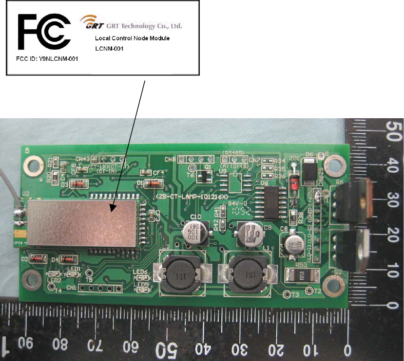
Label & Label Location (FCC ID: Y9NLCNM-001)
Length: 29 mm
Wide: 12 mm
Label Location