GS Instech CC25K700 Cover4G25K User Manual
GS Instruments Co., Ltd. Cover4G25K
User manual
CoverCell25K/100K700
Technician's Operational Manual
& Installation Guide
Ve r. 1 . 0
Version 1.0 September 2010
© 2010, GS Teletech, Inc. 2
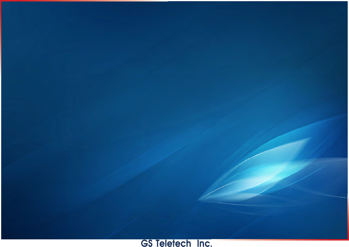
Contents of Box(A)
Contents Picture Quantity Contents Picture Quantity
Repeater 1EA Ground Cable
6.6ft (2m) 1EA
Mounting Bracket 1EA Ground Sems Screw
M4 x 8mm 4EA
Installation Guide CD 1EA Bracket Sems Screw
M6 x 16mm 4EA
Ethernet Cable
6.6ft (2m) 1EA Lag Screw
1/2" x 2" 4EA
Power Cord
6.6ft (2m) 1EA Anchor Bolt Set
1/2" x 2" 4EA
Registration Form 1EA
Version 1.0 September 2010
© 2010, GS Teletech, Inc. 3
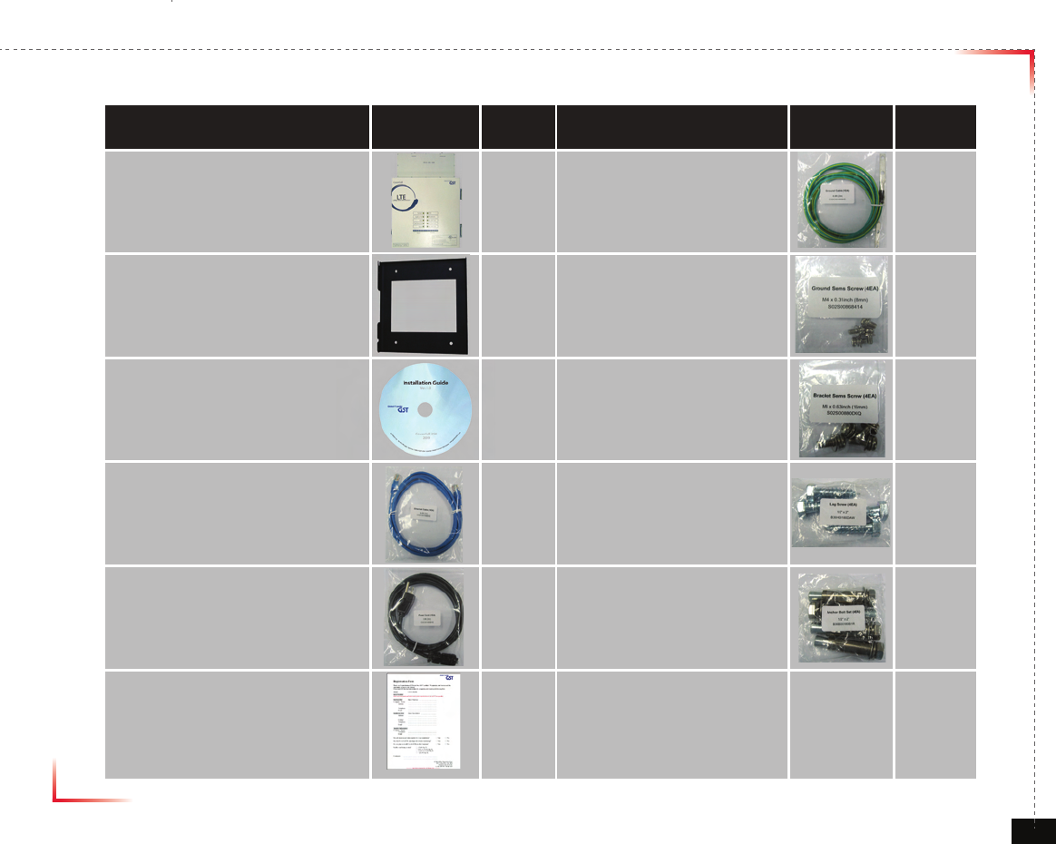
Contents of Box(B)_Option
Contents Picture Quantity Contents Picture Quantity
RF Cable
33ft(10m) 1EA
ANT Pole Set 1Set
RF Cable
66ft(20m) 1EA
Donor ANT 1EA Cable Clamp 12EA
Coverage ANT 1EA (+)FH Tapping Screw for Clamp
Ø4 x 25mm 24EA
Cable Tie 12EA Universal Filter Kit 1EA
Wide Band 2way Splitter
(300MHz - 2.5GHz) 1EA

Version 1.0 September 2010
© 2010, GS Teletech, Inc. 4
The images for the User Interface in this publication may vary from the repeater’s depending on its
S/W Version.
Copyright
© 2010, GS Teletech, Inc.
All Rights Reserved
Printed in Republic of Korea
Revision History
Date Version Changes
09/2010 1.0 Original
Certication
UL/FCC: This equipment complies with UL and FCC
Version 1.0 September 2010
© 2010, GS Teletech, Inc. 5
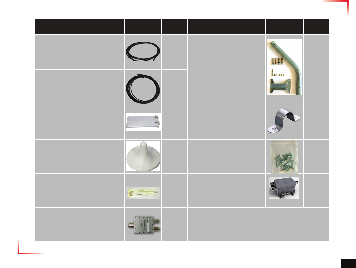
Warnings and Hazards
WARNING! ELECTRIC SHOCK
Opening the BDA (bi-directional amplier) could result in electric shock and may cause severe injury.
WARNING! EXPOSURE TO RF
Working with the repeater while in operation, may expose the technician to RF electromagnetic elds
that exceed FCC rules for human exposure. Visit the FCC website at http://www.fcc.gov/oet/rfsafety
to learn more about the effects of exposure to RF electromagnetic elds.
WARNING! DAMAGE TO EQUIPMENT
Operating the BDA with antennas in very close proximity facing each other could lead to severe damage to the repeater.
RF EXPOSURE & ANTENNA PLACEMENT
Actual separation distance is determined upon gain of antenna used.
Please maintain a minimum safe distance of at least 8 inch while operating near the donor and the server antennas.
Also, the donor antenna needs to be mounted outdoors on a permanent structure.
WARRANTY
Unauthorized opening or tampering the BDA will void all warranties.
One-year Warranty will start when the ownership of CoverCell25K/100K700 is transferring.
CAUTION: REPEATER SHOULD BE INSTALLED AS CLOSE AS POSSIBLE TO POWER SOURCE.
CAUTION: THIS REPEATER IS FOR INDOOR USE ONLY AND SHOULD BE LOCATED INSIDE OF BUILDING.
CAUTION: RISK OF EXPLOSION IF BATTERY ON CONTROLLER BOARD IS REPLACED WITH AN INCORRECT TYPE.
CAUTION: DISPOSE OF USED BATTERIES ACCORDING TO THE INSTRUCTIONS.
!
!
!
!
Version 1.0 September 2010
© 2010, GS Teletech, Inc. 6
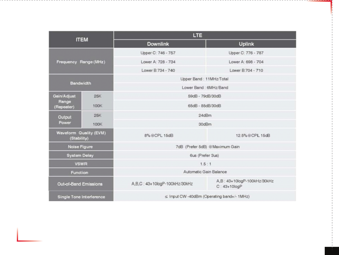
System Specication
Version 1.0 September 2010
© 2010, GS Teletech, Inc. 7
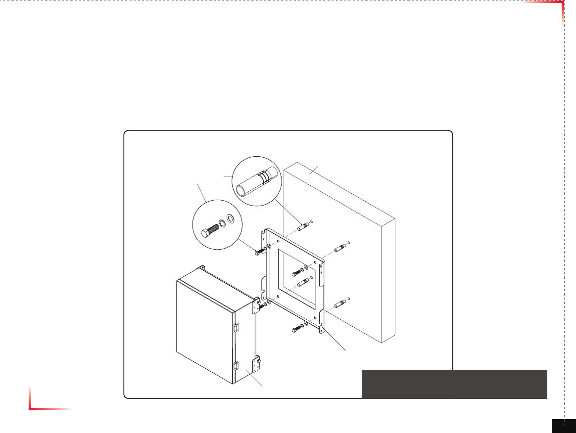
Mounting Repeater
Masonry Wall
1. Using a pencil, mark the location of each of the mounting bracket's four mounting holes on the wall.
2. Drill holes in the wall at the locations marked in step 1.
3. Set the anchors in the wall using a hammer.
4. Locate the four mounting bolts and place a lock washer and at washer on each bolt.
5. Place the mounting bracket over the four holes with anchors, making sure that the washers are on the
repeater side of the mounting bracket. Tighten bolts until secure.
Anchor Bolt Set
1/2" x 2"
RF Repeater
Masonry Wall
Mounting Bracket
<Figure 1> Mounting the Repeater
on a Masonry Wall
Version 1.0 September 2010
© 2010, GS Teletech, Inc. 8
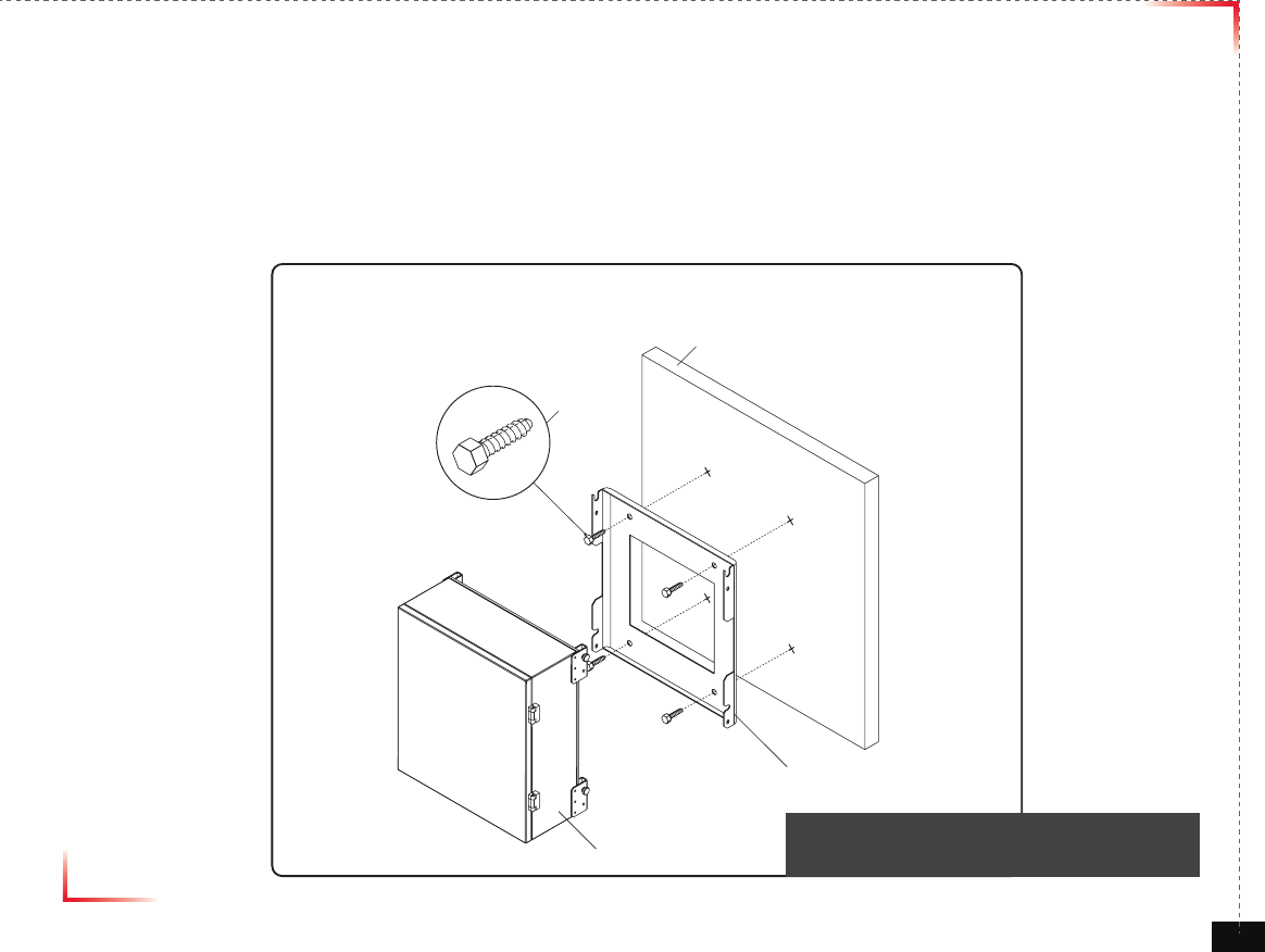
Mounting Repeater
Wood-Framed Wall
1. It is recommended to rst attach a sheet of plywood to the wall. The sheet of plywood should be anchored to the studs
in the wall.
2. Using a pencil, mark the location for each of the mounting bracket's four mounting holes on the plywood.
3. Place the mounting bracket over the four lag screws heads.
4. Thread a lag screw at the positions marked in step 2.
<Figure 2> Mounting the Repeater
on a Wood-Framed Wall
Lag Screw
1/2" x 2"
RF Repeater
Wood-Framed Wall
Mounting Bracket
Version 1.0 September 2010
© 2010, GS Teletech, Inc. 9
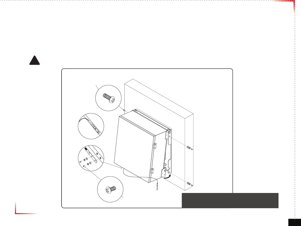
Bracket Sems Screw
M6 x 16 mm
Ground Sems Screw
M4 x 8 mm
Ground lug detail drawing
To approved ground source
!
<Figure 3> Hanging and Grounding
the Repeater
Hanging and Grounding
1. Hang the Repeater from the mounting bracket.
2. Locate the four Bracket Sems Screws with installed washers. Tighten bolts until secure.
3. Locate the ground lug on the underside(or side) of the repeater.
4. Crimp the ground cable to the ground lug.
5. Route the free end of the ground cable to an approved(per local code or practice) ground source.
CAUTION
Ground cable must be properly grounded to provide both EMI and voltage surge protection for the repeater.
Version 1.0 September 2010
© 2010, GS Teletech, Inc. 10
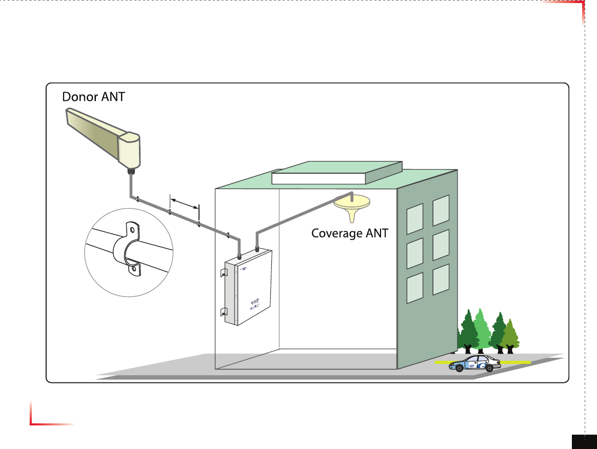
Mounting Coverage & Donor ANT
10ft
Version 1.0 September 2010
© 2010, GS Teletech, Inc. 11
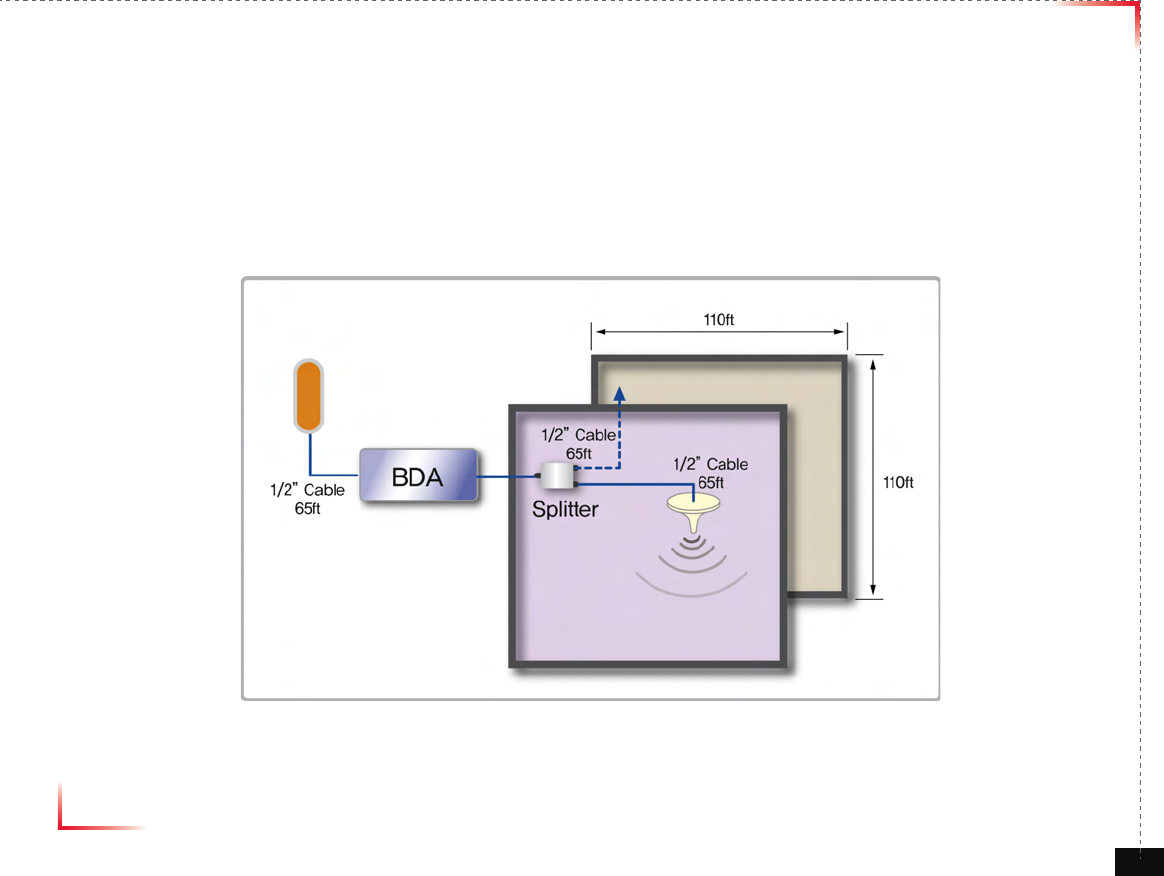
Coverage
• Common Condition
1. System Output Power -> LTE : 0dBm/FA @ pilot
2. Mobile Input Power : -90dBm/FA @ pilot
3. Donor Antenna Gain -> LTE : 8dBi
4. Coverage Antenna -> Common : 2dBi
• SUBURBAN
5. LTE : 1 channel -> 9dBm/total @ EIRP
<Small Room>
Path Loss = 32.44+20Log[Frequency]+20Log[Distance(km)]+Indoor Loss
Version 1.0 September 2010
© 2010, GS Teletech, Inc. 12
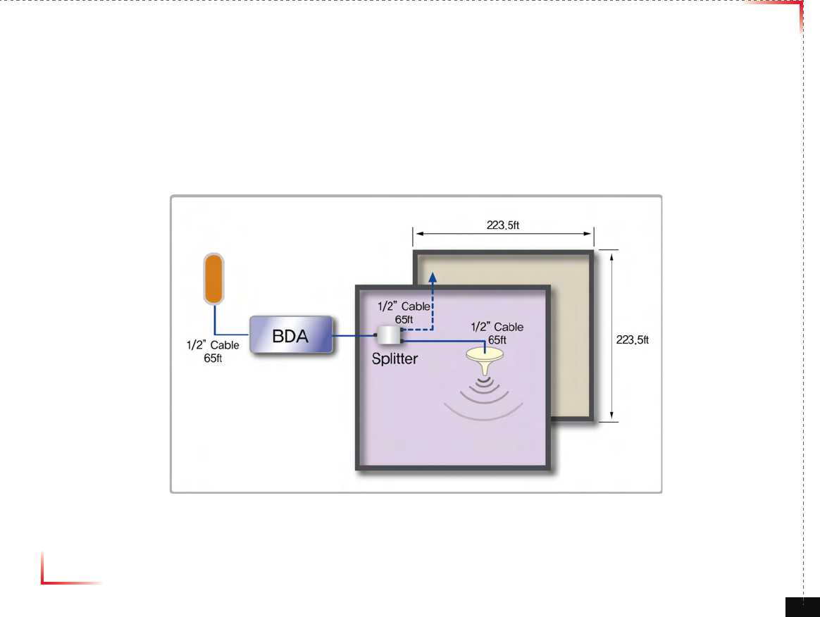
Coverage
• Common Condition
1. System Output Power -> LTE : 6dBm/FA @ pilot
2. Mobile Input Power : -90dBm/FA @ pilot
3. Donor Antenna Gain -> LTE : 8dBi
4. Coverage Antenna -> Common : 2dBi
• SUBURBAN
5. LTE : 1 channel -> 15dBm/total @ EIRP
<Small Room>
Path Loss = 32.44+20Log[Frequency]+20Log[Distance(km)]+Indoor Loss
Version 1.0 September 2010
© 2010, GS Teletech, Inc. 13
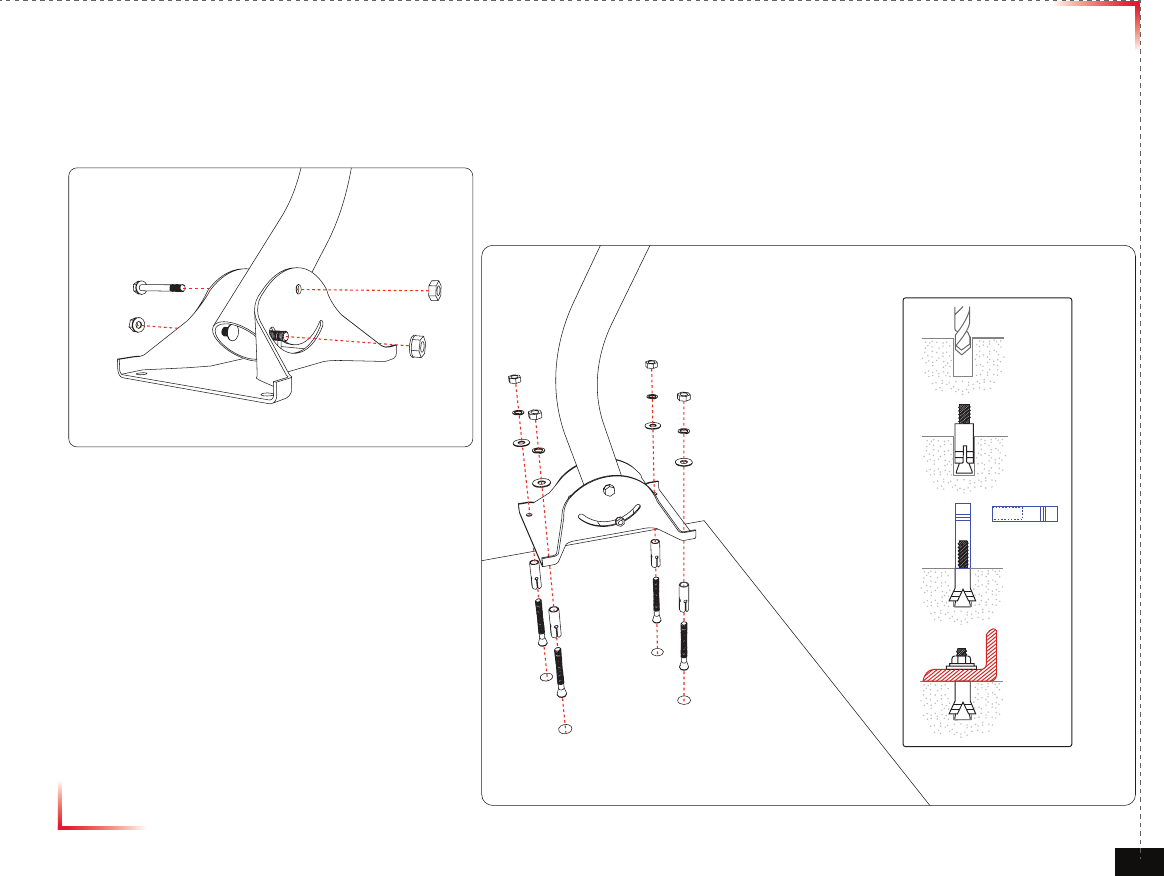
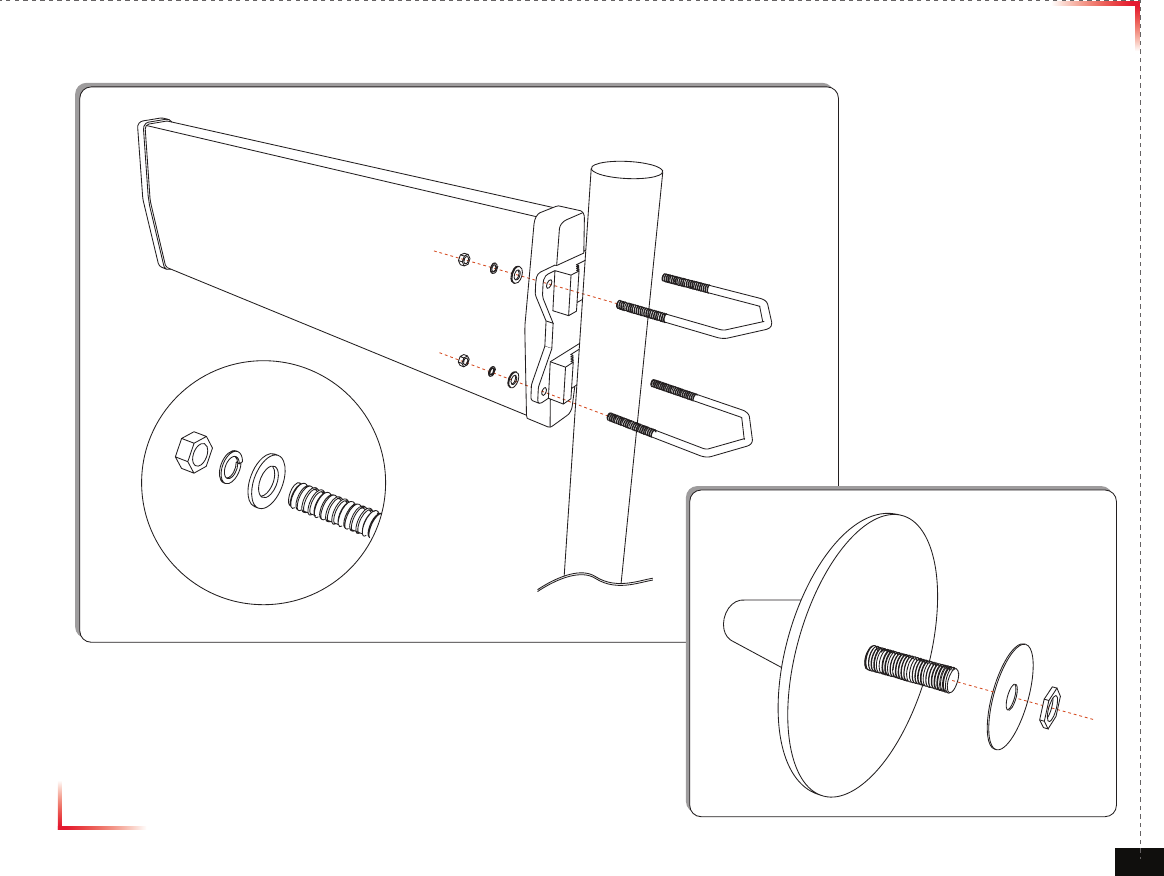
Mounting Donor & Coverage ANT
Mounting Donor ANT Pole
①
②
③
④
Version 1.0 September 2010
© 2010, GS Teletech, Inc. 14
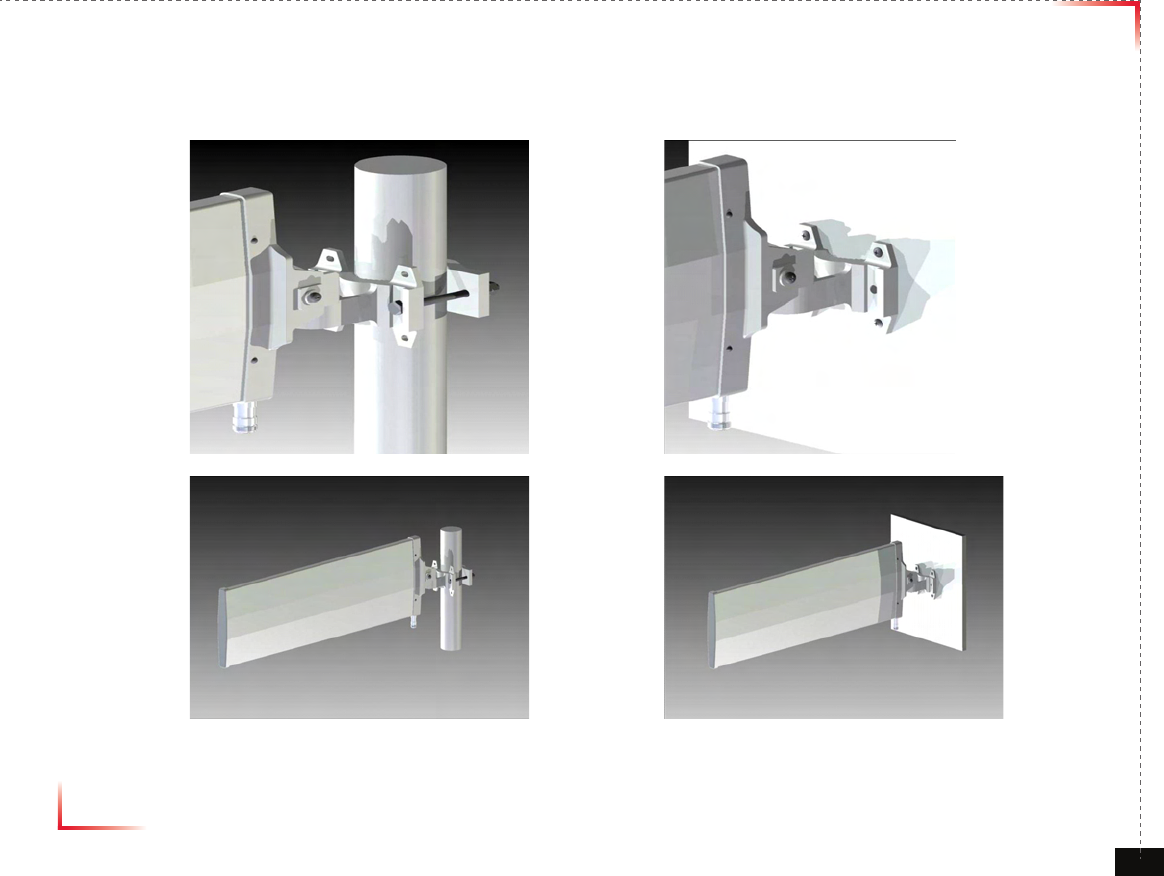
Mounting Donor & Coverage ANT
Version 1.0 September 2010
© 2010, GS Teletech, Inc. 15
Mounting Type
<Pole Mount> <Wall Mount>
Version 1.0 September 2010
© 2010, GS Teletech, Inc. 16
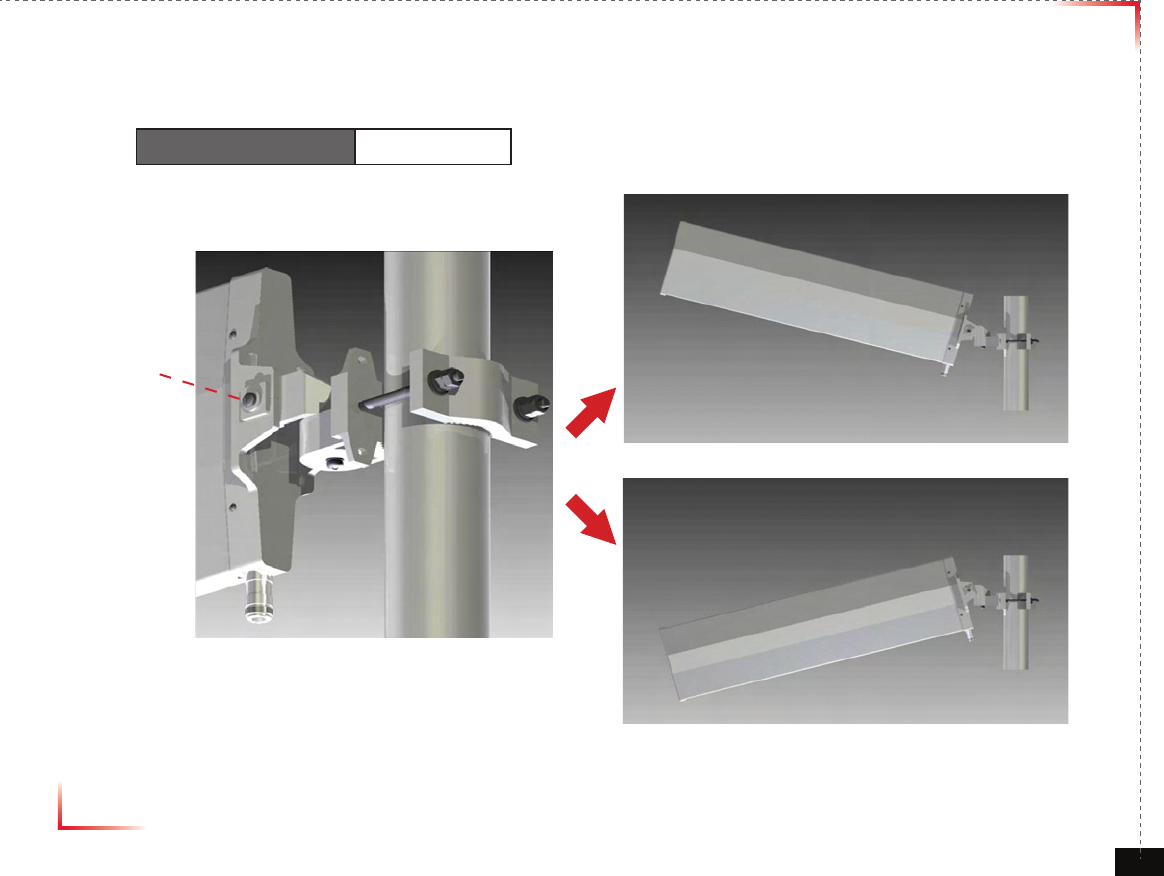
Vertical Tilt
Vertical Beam Width 35 Deg
Bolt
Version 1.0 September 2010
© 2010, GS Teletech, Inc. 17
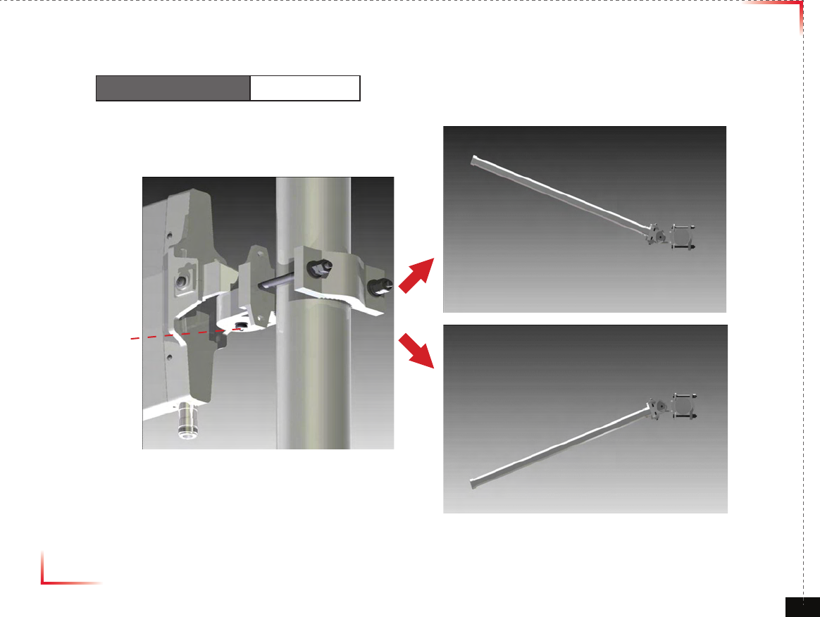
Horizontal Tilt
Horizontal Beam Width 90 Deg
Bolt
Version 1.0 September 2010
© 2010, GS Teletech, Inc. 18
Mounting Coverage & Donor ANT
Item Remark
Donor ANT
(1) Setting the direction of Donor Antenna
(2) A donor antenna needs to be located in a place which maintains maximum receiving signal
levels and attains highest Ec/lo values from BTS.
(3) It is recommended that the antenna needs to be protected by placing it under the protection
angle from a lightening rod.
(4) A donor antenna needs to be away from high pressure and high frequency facilities.
When installing a donor antenna, it needs open spaces at least more than 180 degree.
(5) To get enough isolation between a donor antenna and a coverage antenna, those antennas
needs to be away from each other.
Coverage ANT
(1) Choosing an efcient emitting place – It is recommended that the antenna should not be
blocked by objects.
(2) For signal quality, the cable length needs to be as short as possible.
(3) The antenna needs to be away from other radio frequency radiating objects such as other
antennas, and CCTV equipment.
Warning: In order to avoid the possibility of exceeding the FCC radio frequency exposure limits,
human proximity to the antenna should not be less than 40cm during normal operation.
The gain of the antenna is 8 dBi.

Version 1.0 September 2010
© 2010, GS Teletech, Inc. 19
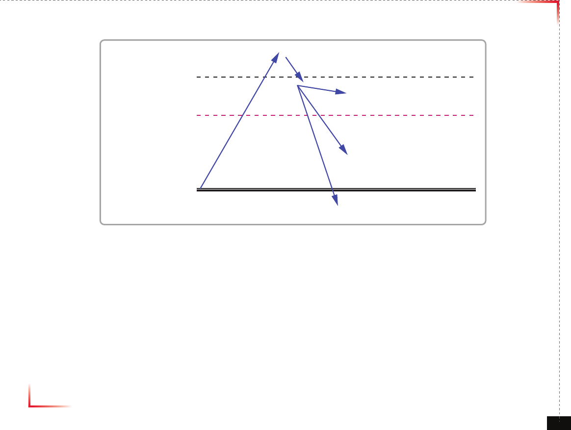
Position Antenna
• Customer specications should be followed for positioning the antennas properly.
<Figure 4> An installer is directing Donor Antenna to
nearby BTS to receive strong input signal.
Version 1.0 September 2010
© 2010, GS Teletech, Inc. 20
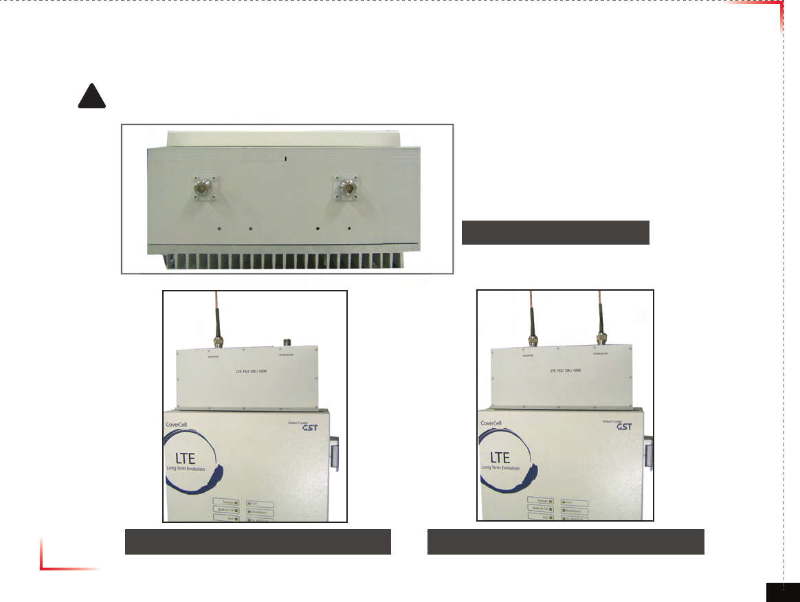
Cable Connections
• Connect Donor and Coverage Antenna
! CAUTION
Do not connect or disconnect cable from ANT port when power is ON
<Figure 5> ANT Ports
<Figure 6> DONOR ANT Port Connection <Figure 7> Covergare ANT Port Connection
Version 1.0 September 2010
© 2010, GS Teletech, Inc. 21
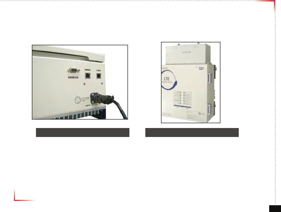
Connecting Power Cable and LED Light Veri cation
• Connect Power Cable
• When turning on the repeater, AGS (Auto Gain Setup) is automatically activated, which shows LED indicators are
turned on one by one.
• After all the LEDs are on, AGS is complete.
• Please verify that all the LEDs are indicating proper input and output levels.
<Figure 9> AC Power Port Connection <Figure 10> Verifi cation of LED Lights
Version 1.0 September 2010
© 2010, GS Teletech, Inc. 22
AGS Algorithm description
Oscillation can be reduced in case that 3dB Attenuation is increased in an excess of Isolation Gap
ATT status value : 0~2.5dB (Shutdown on , DL/UL PAM on, DL Always OSC on)
3dB~30dB (ALC on ,shutdown on , DL/UL PAM on, DL Always OSC on)
Over 30dB (uplink OSC Alarm , DL/UL PAM off )
References
1. Isolation Check in initial set up or Reset
2. Monitoring Oscillation comparing to minimum/maximum Noise Floor level
3. When Oscillation occurred, repeater attempts to stabilize Isolation through Gain control function
4. Shutdown repeater when Oscillation still occurs in Minimum Gain
5. Automatic Recovery Algorithm conversion after Shutdown status
Isolation Gap
ATT: 3dB
Max ATT (30dB)
Shutdown on ,DL/UL PAM on
DL Always OSC on
3dB Attenuation will be increased in an access of Isolation Gap
ALC on , shutdown on ,DL/UL PAM on
DL Always OSC on
Uplink OSC Alarm
DL/UL PAM OFF
isolation Gap value Comparison of
isolation Gap value status and reduced
by ATT 3dB
Version 1.0 September 2010
© 2010, GS Teletech, Inc. 23
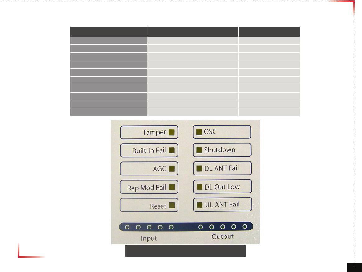
LED Indicators
LED Status Remark Application Status
Tamper Tamper Enable
Built- in t Fail Built-in test fail Enable
AGC AGC Active Enable
Rep Mod Fail Replaceable module fail Enable
Reset Reset engaged Enable
OSC OSC detected Enable
Shutdown Shutdown Enable
DL ANT Fail Donor ANT circuit fail Enable
DL Out Low Donor Power too low Enable
UL ANT Fail Coverage ANT circuit fail Enable
<Figure 11> Front LED Display
Version 1.0 September 2010
© 2010, GS Teletech, Inc. 24
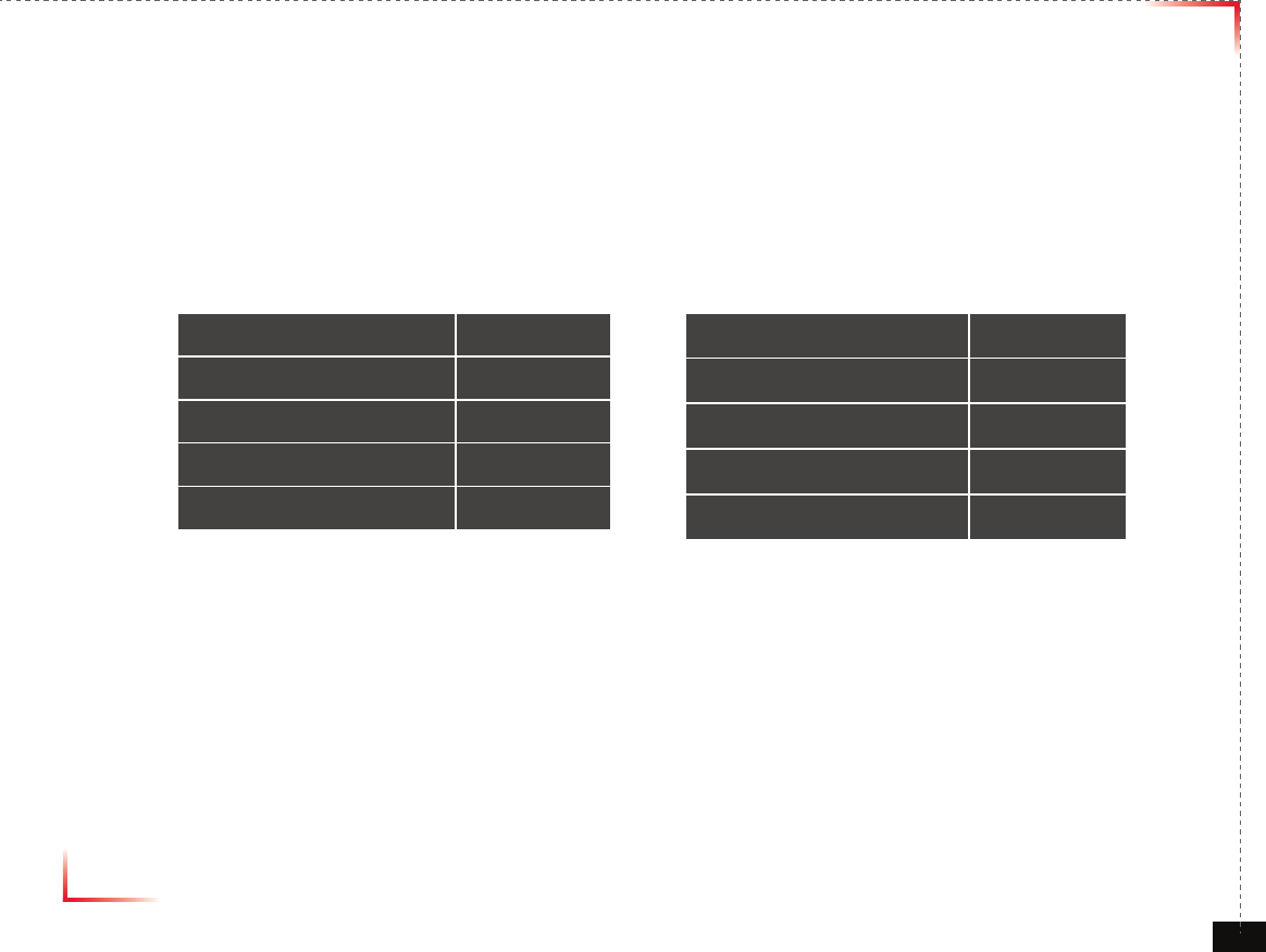
Input /Output Power Signal
• Please note the number of LED bars indicates the RSSI signal strength level at the Donor & Coverage ANT port.
The tables below indicate the levels.
< Input > < Output >
Less than -75dBm LED 1bar
-74.5dBm ~ -70dBm LED 2 bars
-69.5dBm ~ -65dBm LED 3 bars
-64.5dBm ~ -60dBm LED 4 bars
More than -59.5dBm LED 5 bars
Less than +4.5dBm LED 1bar
+5dBm ~ +9.5dBm LED 2 bars
+10dBm ~ +14.5dBm LED 3 bars
+15dBm ~ +19.5dBm LED 4 bars
More than +20dBm LED 5 bars
Version 1.0 September 2010
© 2010, GS Teletech, Inc. 25
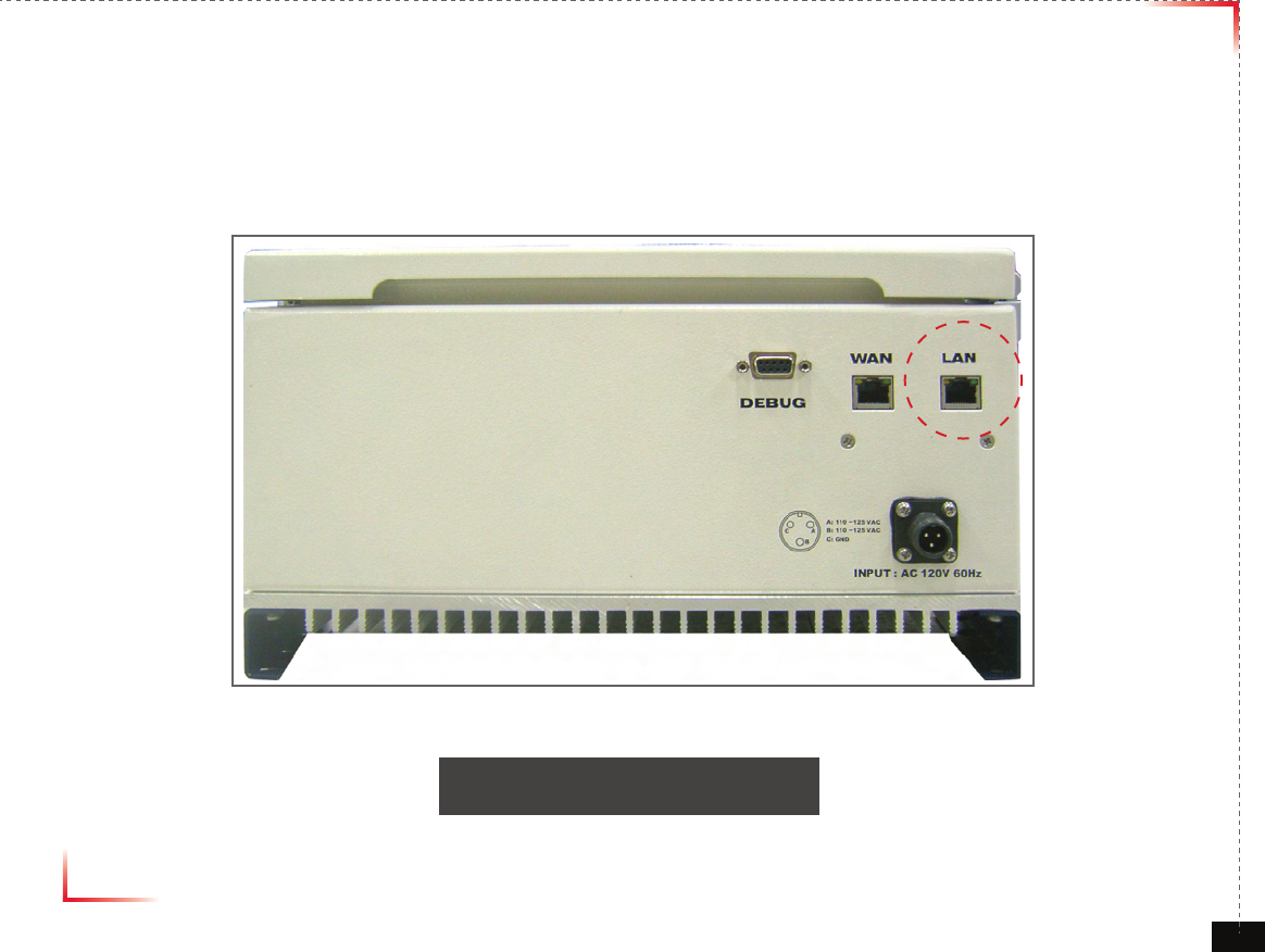
Web UI
• Before connecting to repeater, disable wireless networking functions and remove wireless broadband card.
• Connect Ethernet Crossover cable from repeater LAN port to laptop.
<Figure 12> WAN Port Display
Version 1.0 September 2010
© 2010, GS Teletech, Inc. 26
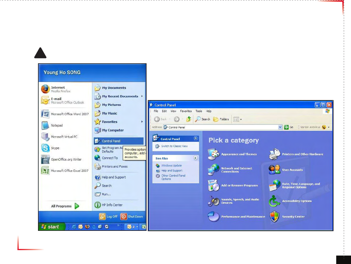
Connecting to Web UI
1. Start-> Control Panel-> Network and Internet Connections
! CAUTION
Disable wireless connections and remove wireless broadband card.
Version 1.0 September 2010
© 2010, GS Teletech, Inc. 27
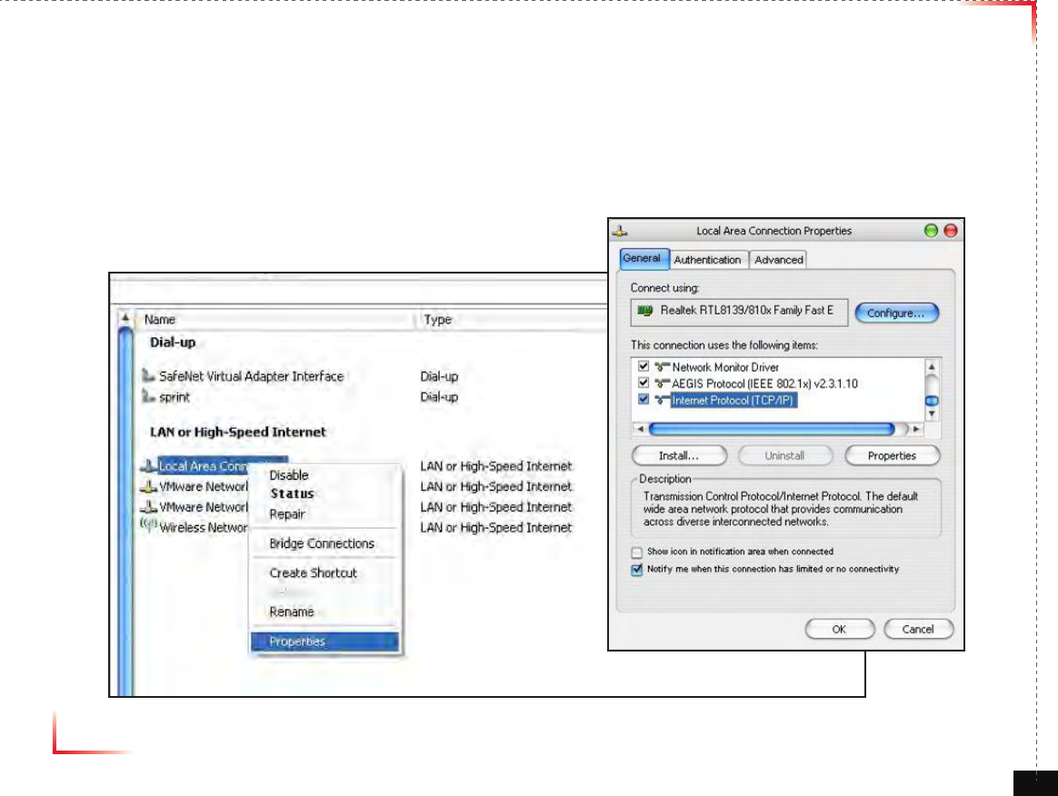
Connecting to Web UI
2. Right click Local Area Connections and choose Properties
- If your laptop is displaying multiple LAN’s, verify which one is used for repeater connection.
3. Click Internet Protocol (TCP/IP) on General Tab and click Properties
Version 1.0 September 2010
© 2010, GS Teletech, Inc. 28
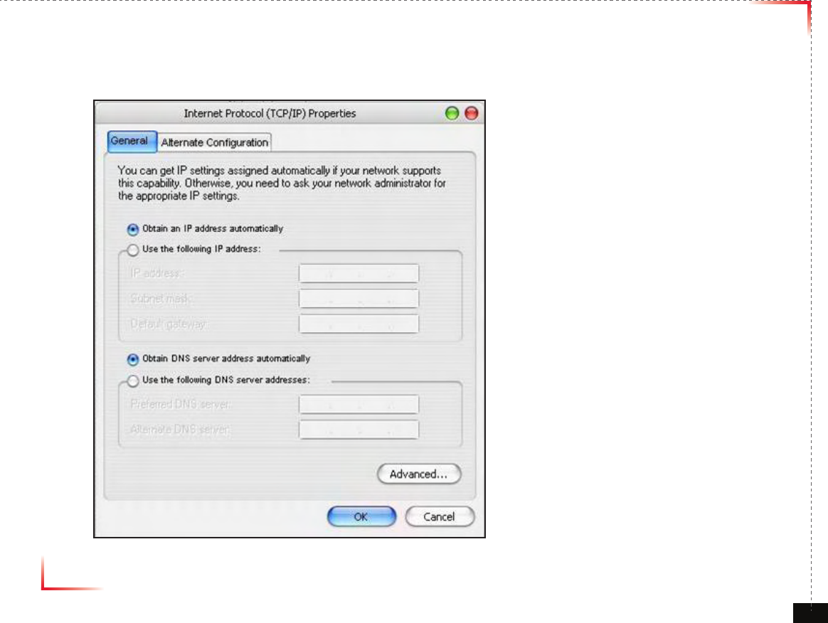
On General Tab
4. Choose “Obtain IP address automatically”
5. Choose “Obtain DNS server address
automatically”
6 . Click “OK” to close Properties
7. Click “OK” to close Properties
Version 1.0 September 2010
© 2010, GS Teletech, Inc. 29
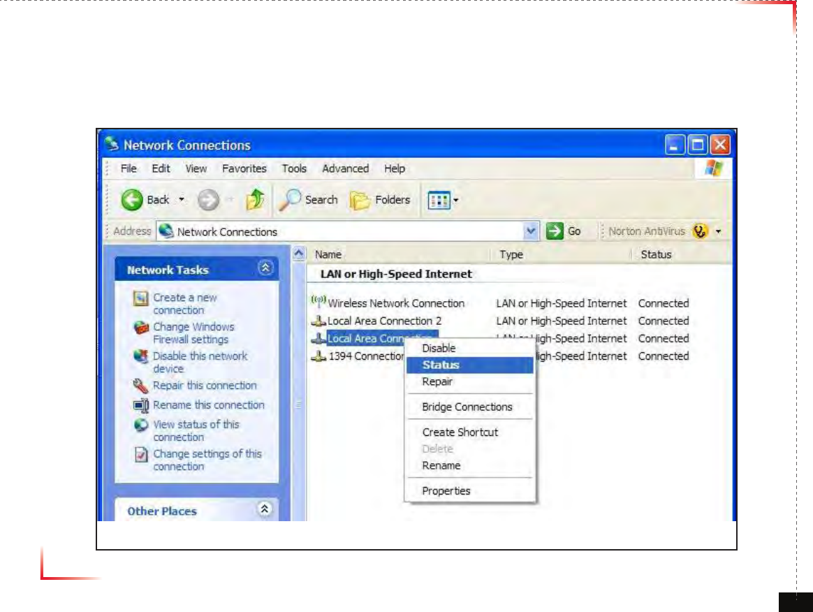
Connecting to Web UI
8. Right click Local Area Connections and choose Status
Version 1.0 September 2010
© 2010, GS Teletech, Inc. 30
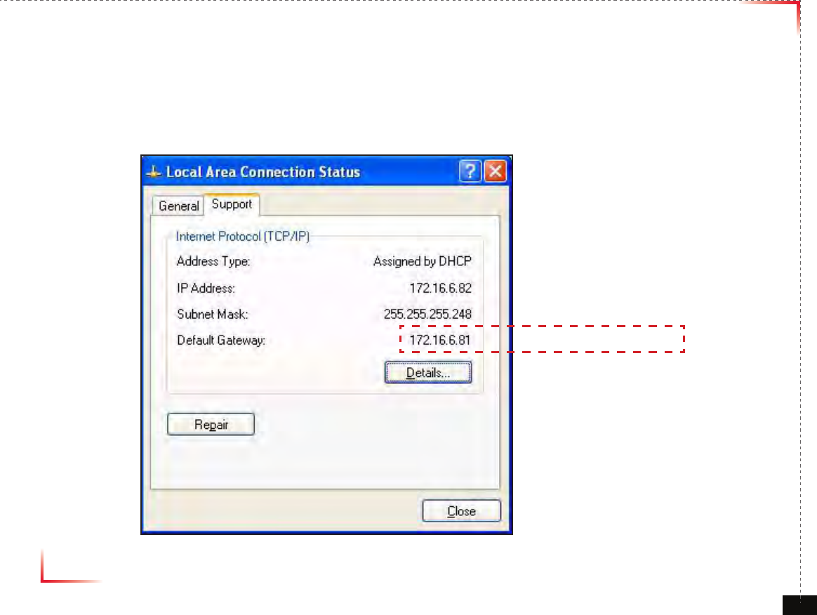
Verify Assigned IP Address
9. Click on “Support” tab.
10. Verify assigned Default Gateway at local connection. (If IP address is not assigned, please click repair.)
11. Close all windows when nished.
Repeater's IP Adress
Version 1.0 September 2010
© 2010, GS Teletech, Inc. 31
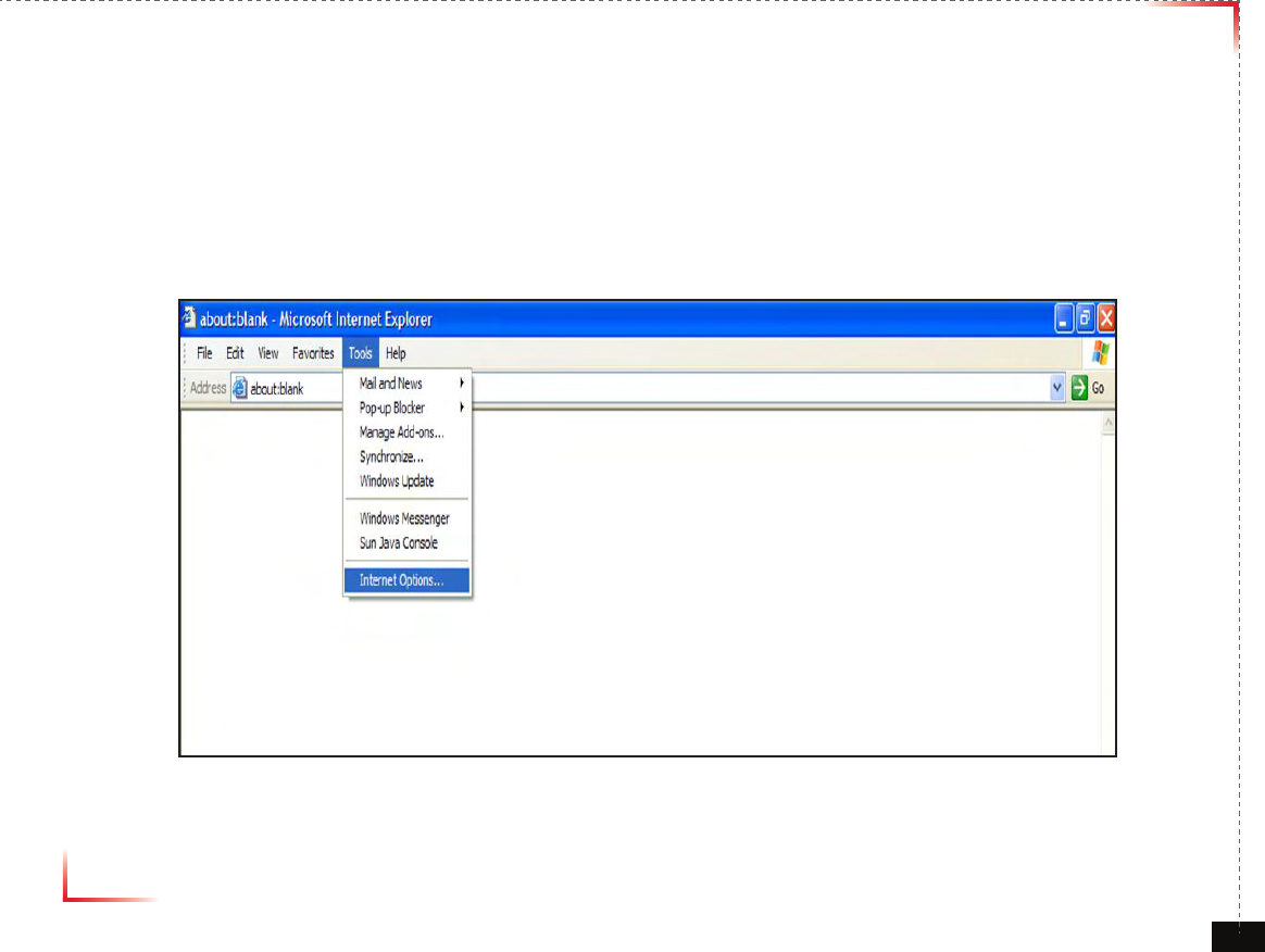
Internet Explorer Option Settings
• Proceed step by step as indicated in the following slides to delete all temporary internet les and records.
1. Open Internet Explorer -> Tools -> Internet Options
Version 1.0 September 2010
© 2010, GS Teletech, Inc. 32
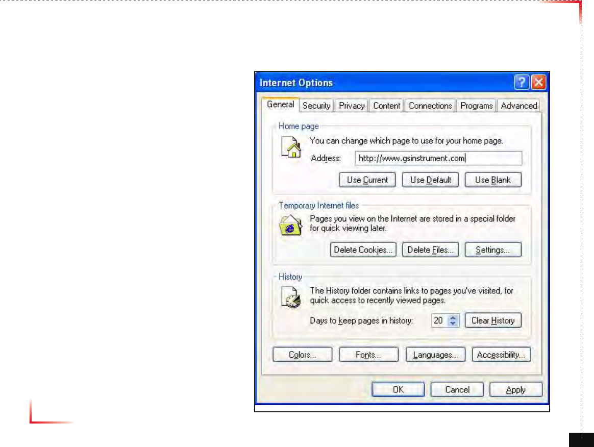
Browser History Options
On the “General“ tab, in the “Temporary Internet les” section:
2. Click "Delete Cookies...“
3. Click "Delete Files...“
4. Click “Apply”
5. Click “OK”
Version 1.0 September 2010
© 2010, GS Teletech, Inc. 33
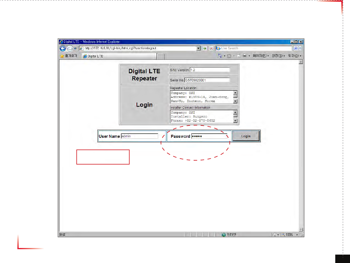
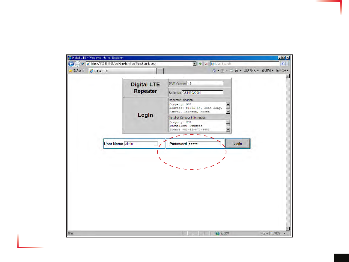
Login Screen
Enter Default Gateway’s IP address into address bar as previously described, you
will be redirected to Login. Default User Name is ‘admin’, and default Password is
‘admin’. You may need to change password as described in the User Management
section.
172.16.6.81
admin
Version 1.0 September 2010
© 2010, GS Teletech, Inc. 34
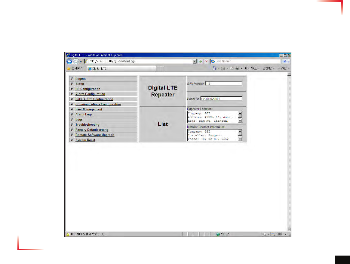
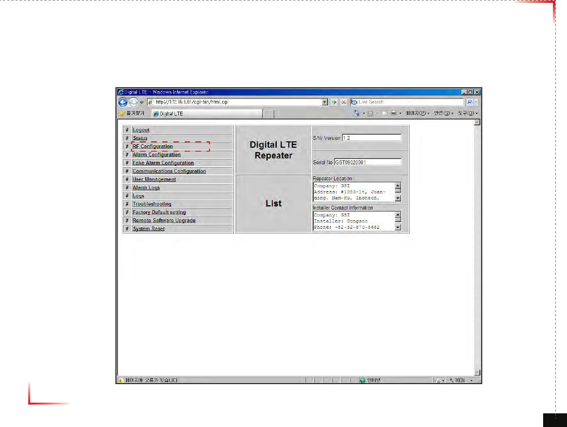
List Menu
• After you log in, you can see various menu page links related to the equipment.
Version 1.0 September 2010
© 2010, GS Teletech, Inc. 35
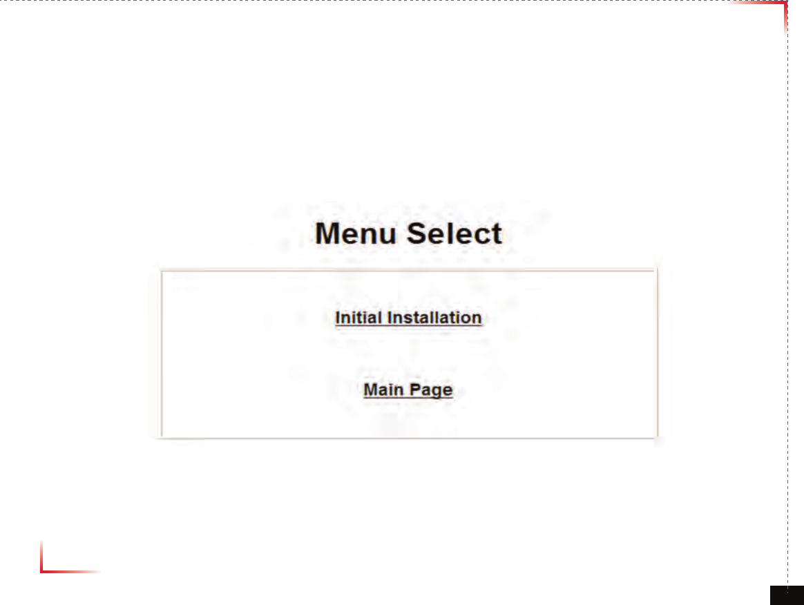
Setup Wizard
• Menu Select Page after logging
• Click “ Initial Installation” for Setup Wizard phase
• Waiting Time: Real-time

Version 1.0 September 2010
© 2010, GS Teletech, Inc. 36
Setup Wizard
• Repeater Location setting
• Click “Apply” for updating
• Click “Skip” without any renewal
• Waiting Time: Real-time
Version 1.0 September 2010
© 2010, GS Teletech, Inc. 37
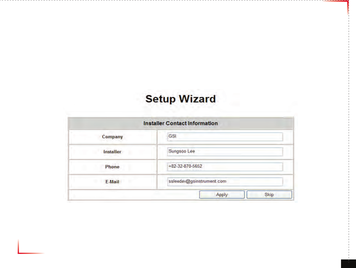
Setup Wizard
• Installer Contact Information setting
• Click “Apply” for updating
• Click “Skip” without any modi cation
• Waiting Time: Real-time
Version 1.0 September 2010
© 2010, GS Teletech, Inc. 38
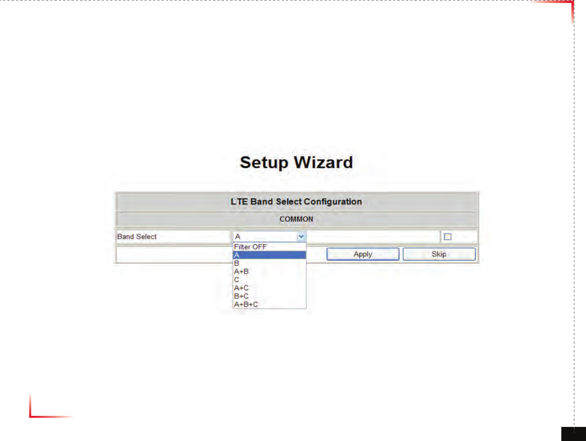
Setup Wizard
• LTE Band Select Configuration setting
• Click “Apply” for updating
• Click “Skip” without any modification
• Waiting Time: Real-time
Version 1.0 September 2010
© 2010, GS Teletech, Inc. 39
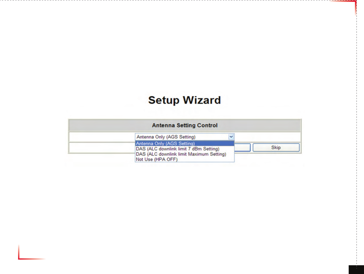
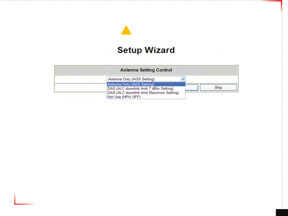
Setup Wizard
• Antenna Setting Control setting
• Click “Apply” for updating
• Click “Skip” without any modification
• Waiting Time: Real-time
Version 1.0 September 2010
© 2010, GS Teletech, Inc. 40
Setup Wizard
• Waiting (Operating) Time:
- Typical: 3mins
- Maximum: 5mins
1. Antenna only (AGS setting) is for Auto Gain Setting to optimize this repeater for eld conditions
a. Every limit level (AGC, Down/Uplink ALC) is normal (example : Standard output power)
b. Auto Gain Setting will run
2. DAS (ALC downlink Limit 7dBm Setting) option is used for connecting this repeater to DAS equipment (LGC DAS,
Mobile Access DAS etc), and following condition should be controlled.
a. AGC turn Off
b. ALC turn On
c. Gain Balance turn Off
d. ALC downlink limit value set +7dBm
e. ALC uplink limit value set normal output power (example : Standard output power)
f. Shut down turn On
g. HPA turn On, If HPA turn off
h. delay alarm reporting time set 5 min
3. DAS (ALC downlink Limit Maximum Setting) option is used for connecting Passive DAS equipment, and 7dB downlink
limit value is set as normal output power level
(Example: Standard output power)
!CAUTION
Please make Path On when you run Setup Wizard if Path Off set
Version 1.0 September 2010
© 2010, GS Teletech, Inc. 41
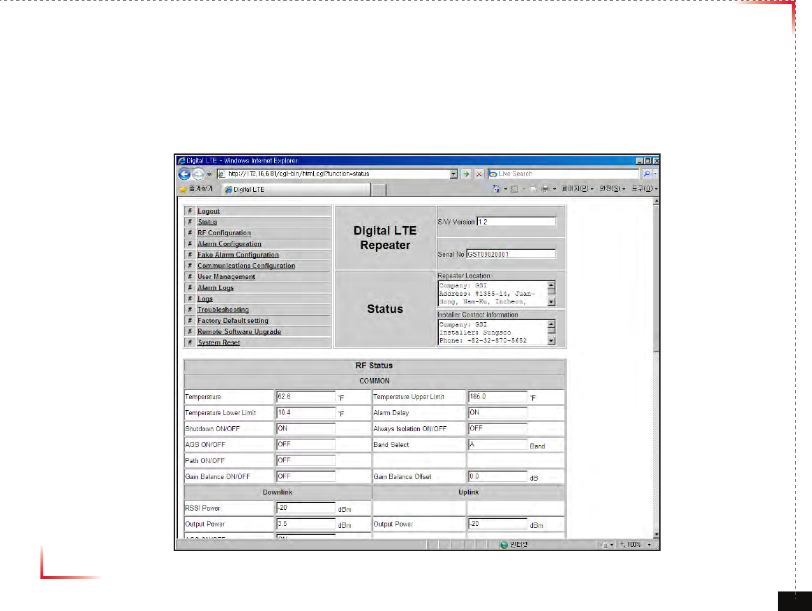
Status Page
• Default D/L and U/L are set at minimum Gain.
• The default values in various fields will differ with different models of CoverCell25K/100K700 Repeaters.
• In order to view other pages, you can click the desired menu on the top-left corner of all pages.
• Changes can be made on the Status Page. This page is for checking the repeater’s conditions and settings.
Version 1.0 September 2010
© 2010, GS Teletech, Inc. 42
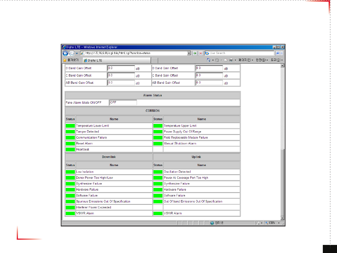
Status Page
• When an alarm goes off, the color of Status turns red.
Version 1.0 September 2010
© 2010, GS Teletech, Inc. 43
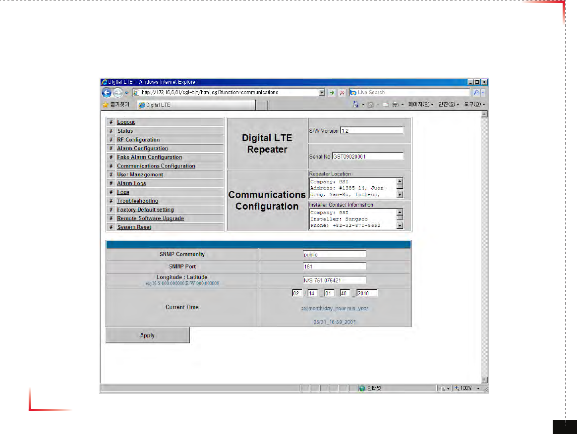
Communications Conguration
• Click on the Communications Conguration link.
Version 1.0 September 2010
© 2010, GS Teletech, Inc. 44
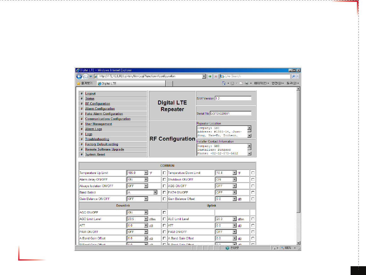
RF Conguration
• Click the RF Configuration link.
• This menu is where installer will actually configure the Repeater.
• You can change various RF values of the equipment on this page.
Version 1.0 September 2010
© 2010, GS Teletech, Inc. 45
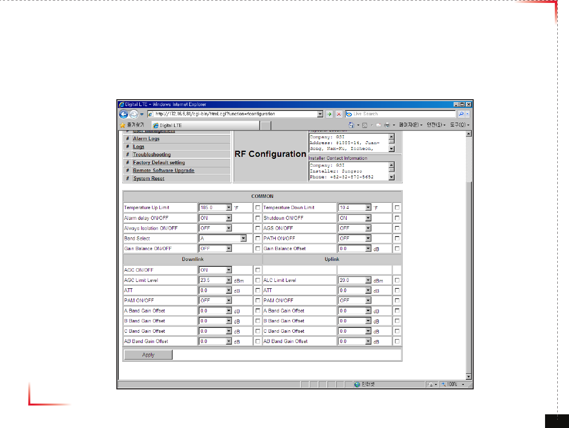
RF Conguration
•
In case that screen resolution is 1024 x 768, you may need to use scroll bars to view all.
•
Changes will not take effect until you click “Apply” button.
•
The default values in various fields will differ with different models of
CoverCell25K/100K700
Repeaters.
Version 1.0 September 2010
© 2010, GS Teletech, Inc. 46
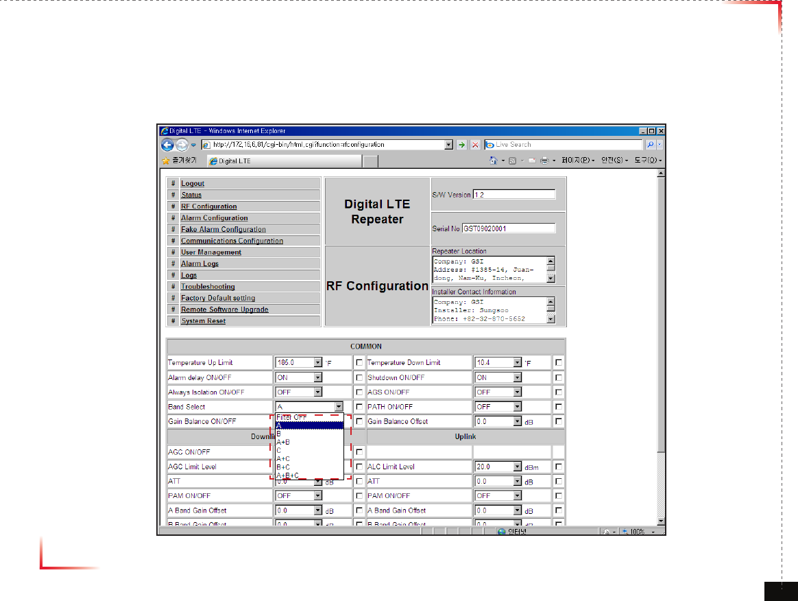
Bandwidth and Frequency Selection
1.
Login as admin as above.
admin
Version 1.0 September 2010
© 2010, GS Teletech, Inc. 47
Bandwidth and Frequency Selection
2.
Click RF configuration
Version 1.0 September 2010
© 2010, GS Teletech, Inc. 48
Bandwidth and Frequency Selection
3.
Choose Bandwidth and select bandwidth users want.
Depending on the bandwidth, the frequency will be set accordingly
Version 1.0 September 2010
© 2010, GS Teletech, Inc. 49
Bandwidth and Frequency Selection
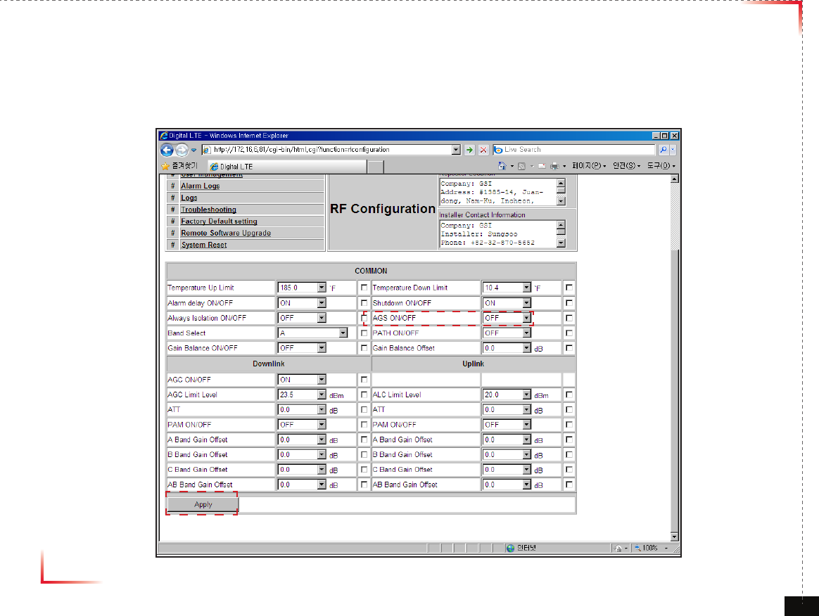
6.
Click Apply if all the setting is done.
Please set AGS “ON”, CoverCell25K/100K700 will remember the status of AGS and perform AGS on rebooting.
Version 1.0 September 2010
© 2010, GS Teletech, Inc. 50
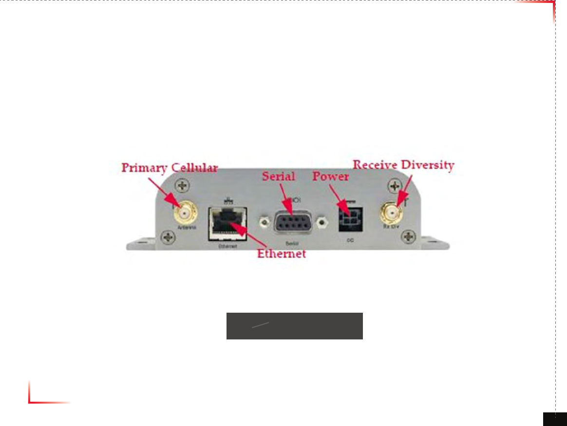
RavenX Setting
•
RavenX is not supplied with Repeater and can be purchased separately from Kentrox.
•
An antenna or antenna cable should be connected to “Primary Celluar” port in Figure 13.
•
One end of an ethernet cable should be connected to “Ethernet” in Figure 1, the other end should be connected to WAN
port in CoverCell25K/100K700.
•
Power should be connected to “Power” in Figure 1. Power supply is provided with RavenX.
•
RavenX will work with CoverCell25K/100K700 with its default setting.
•
RavenX will work with CoverCell25K/100K700 with its default setting.
<Figure 13> RavenX Setting
Version 1.0 September 2010
© 2010, GS Teletech, Inc. 51
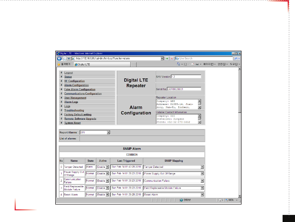
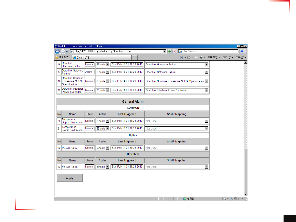
Alarm Conguration
•
Click Alarm Configuration link.
•
In case that Report Alarms is OFF, all alarms will be disabled. In case that Report Alarm is ON,
you can enable and disable individual alarms.
Version 1.0 September 2010
© 2010, GS Teletech, Inc. 52
Alarm Conguration
•
In case that screen resolution is 1024 x 768, you may need to use scroll bars to view all.
Changes will not be made effective until you click “Apply” button.
Version 1.0 September 2010
© 2010, GS Teletech, Inc. 53
Alarm List
Category Alarm
General
Tamper
Power Supply out of range
Communication
Field replaceble module Fail
Reset alarm
Manual shutdown alarm
Heart beat
Uplink
OSC detect
Power at CVG port too high
Synthesizer Fail
Hardware Fail
Software Fail
Out of Band emission
Downlink
Donor power too high/low
Low isolation
Synthesizer Fail
Hardware Fail
Software Fail
Spurious emission
Interferer power exceed
Version 1.0 September 2010
© 2010, GS Teletech, Inc. 54
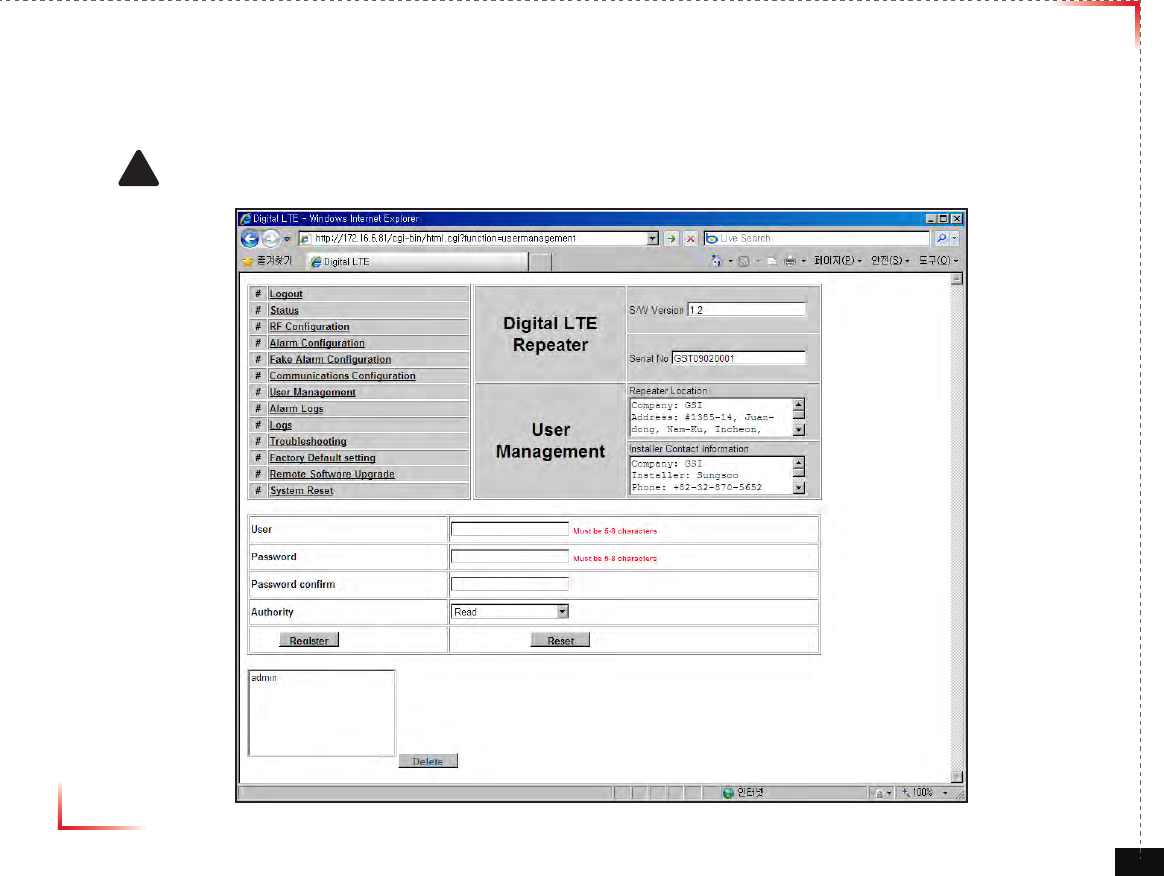
User Management
•
Click on the User Management link.
•
On this page you can create and delete users, change passwords, and assign authorities to individual users.
•
Read/Write Authority means that the user can change various values.
•
Super User is very similar to an Administrator account.
! CAUTION
DO NOT DELETE 'admin'
Version 1.0 September 2010
© 2010, GS Teletech, Inc. 55
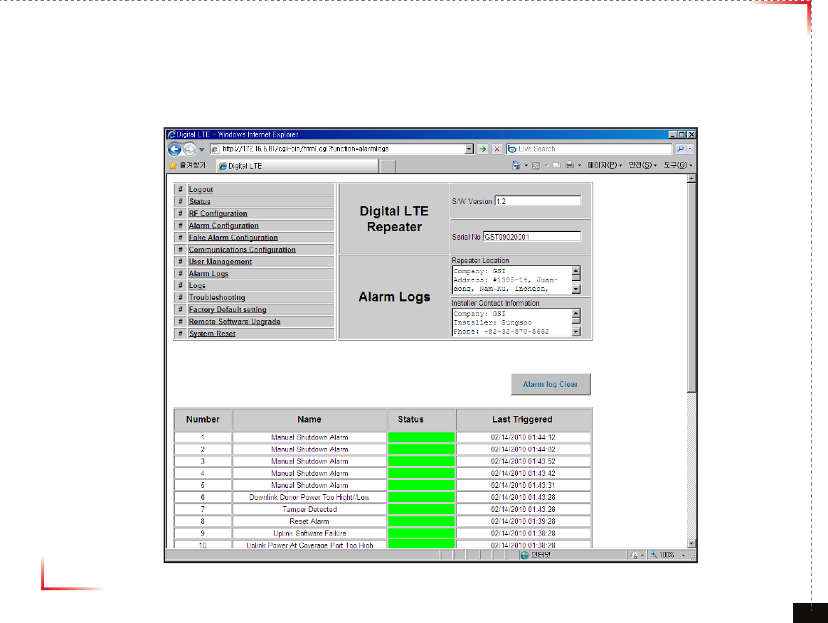
Alarm Logs
• Click on the Alarm Logs link.
• You can see Alarm Logs regarding Web UI operation. Alarm Logs will maintain a history of up to 30 operations.
Version 1.0 September 2010
© 2010, GS Teletech, Inc. 56
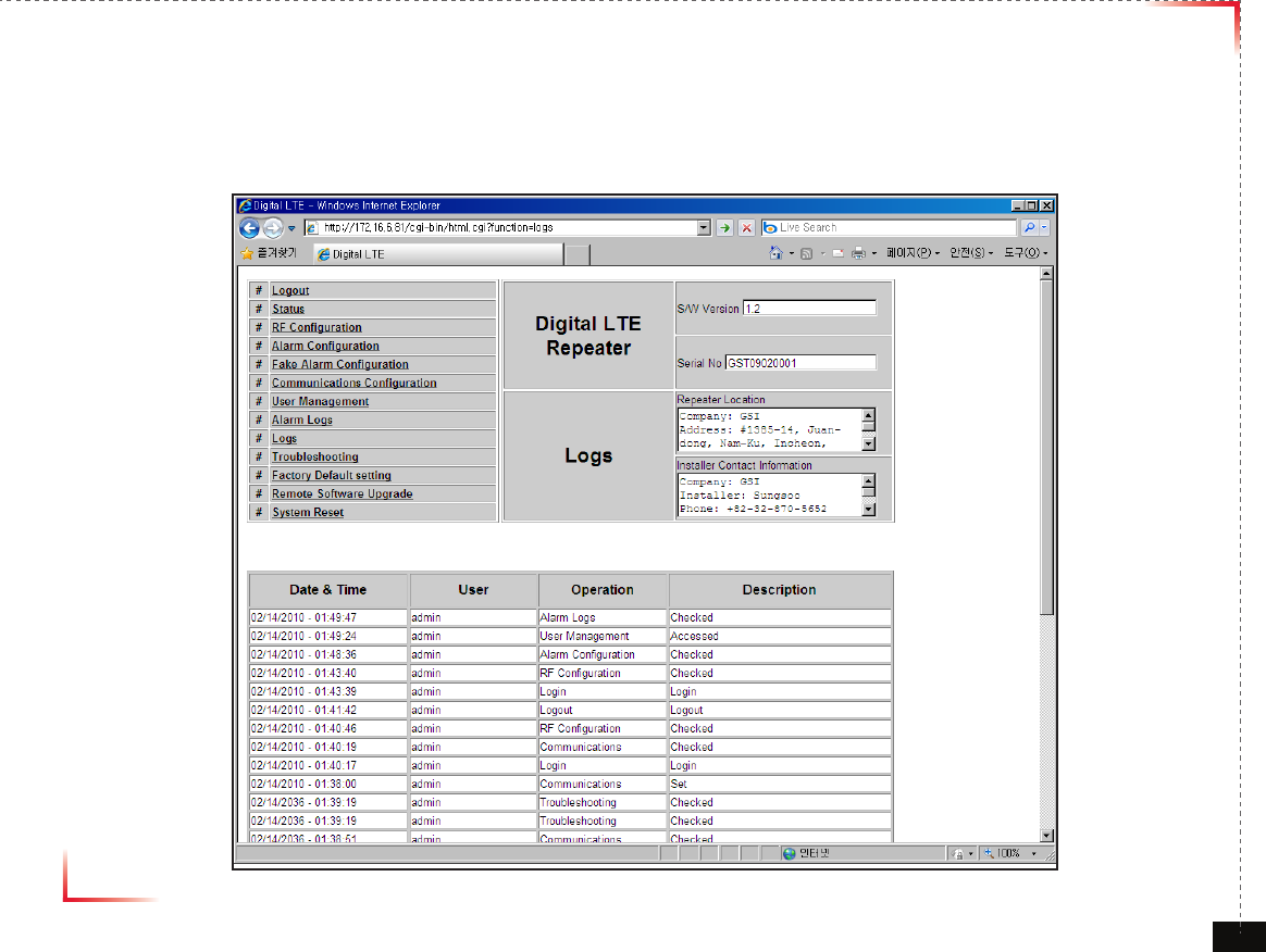
Logs
• Click on the Alarm Logs link.
• You can see Alarm Logs regarding Web UI operation. Logs will maintain a history of up to 30 operations.
Version 1.0 September 2010
© 2010, GS Teletech, Inc. 57
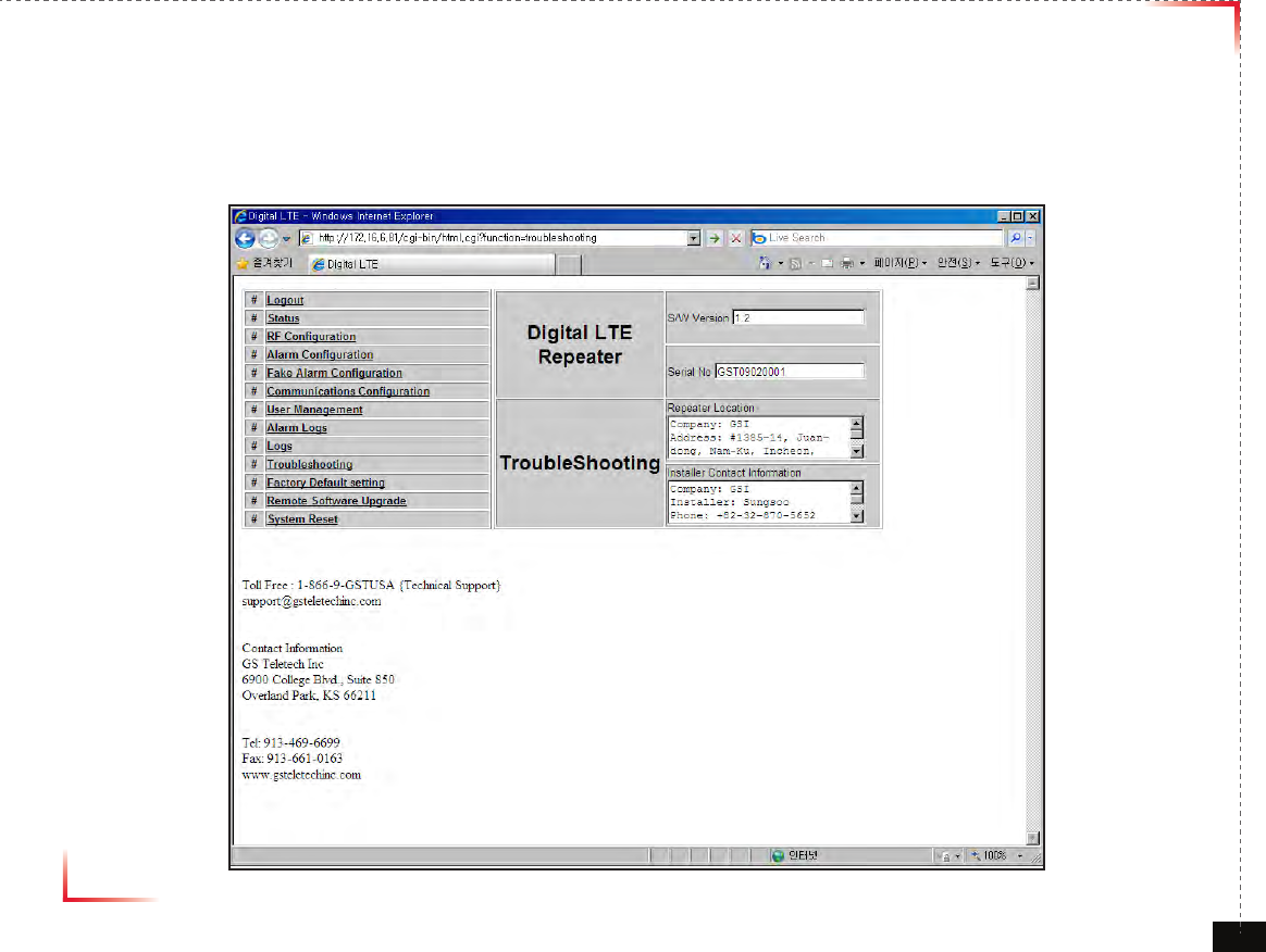
Troubleshooting Guide
• Click on the Troubleshooting link.
• You can refer to this page for a general troubleshooting guide.
• In case that screen resolution is 1024 x 768, you may need to use scroll bars to view all.
Version 1.0 September 2010
© 2010, GS Teletech, Inc. 58
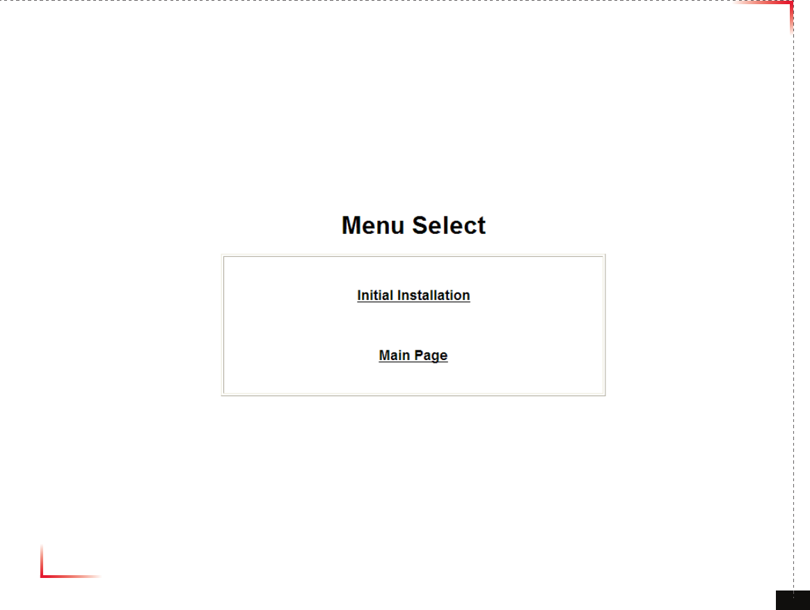
Troubleshooting
• Please click “Main Page” on Menu Select Page after logging.
Version 1.0 September 2010
© 2010, GS Teletech, Inc. 59
Troubleshooting
• “Troubleshooting” Click

Version 1.0 September 2010
© 2010, GS Teletech, Inc. 60
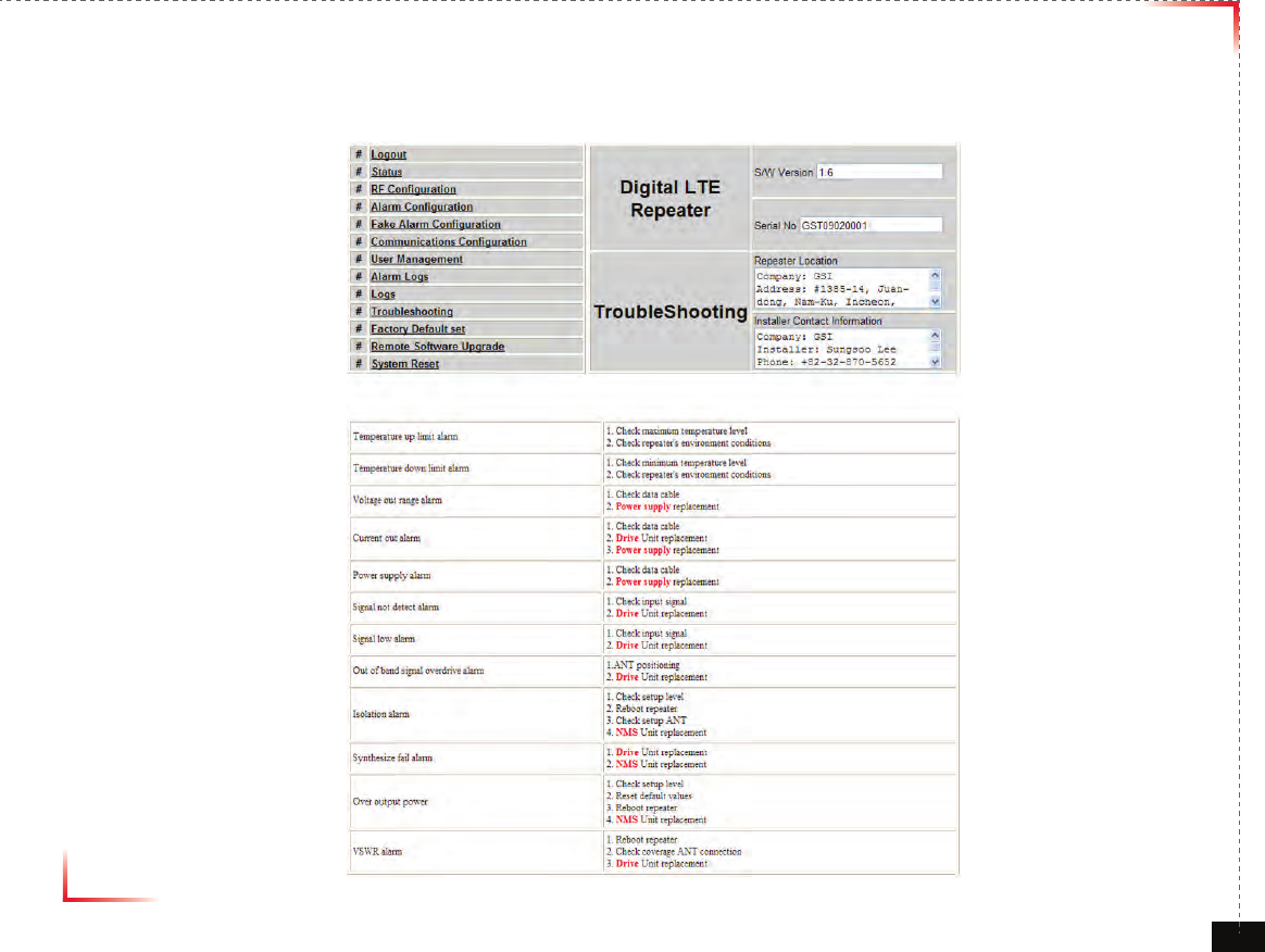
Troubleshooting
• Temperature up limit alarm
- Check maximum temperature level
- Check repeater’s environment conditions
• Temperature down limit alarm
- Check minimum temperature level
- Check repeater’s environment conditions
• Voltage out range alarm
- Check data cable
- Power supply replacement
• Current out alarm
- Check data cable
- Drive Unit replacement
- Power supply replacement
• Power supply alarm
- Check data cable
- Power supply replacement
• Signal not detect alarm
- Check input signal
- Drive Unit replacement
• Signal low alarm
- Check input signal
- Drive Unit replacement

Version 1.0 September 2010
© 2010, GS Teletech, Inc. 61
Troubleshooting
• Out of band signal overdrive alarm
- ANT positioning
- Drive Unit replacement
• Isolation alarm
- Check setup level
- Reboot repeater
- Check setup ANT
- NMS Unit replacement
• Synthesize fail alarm
- Drive Unit replacement
- NMS Unit replacement
• Over output power
- Check setup level
- Reset default values
- Reboot repeater
- NMS Unit replacement
• VSWR alarm
- Reboot repeater
- Check coverage ANT connection
- Drive Unit replacement
Version 1.0 September 2010
© 2010, GS Teletech, Inc. 62
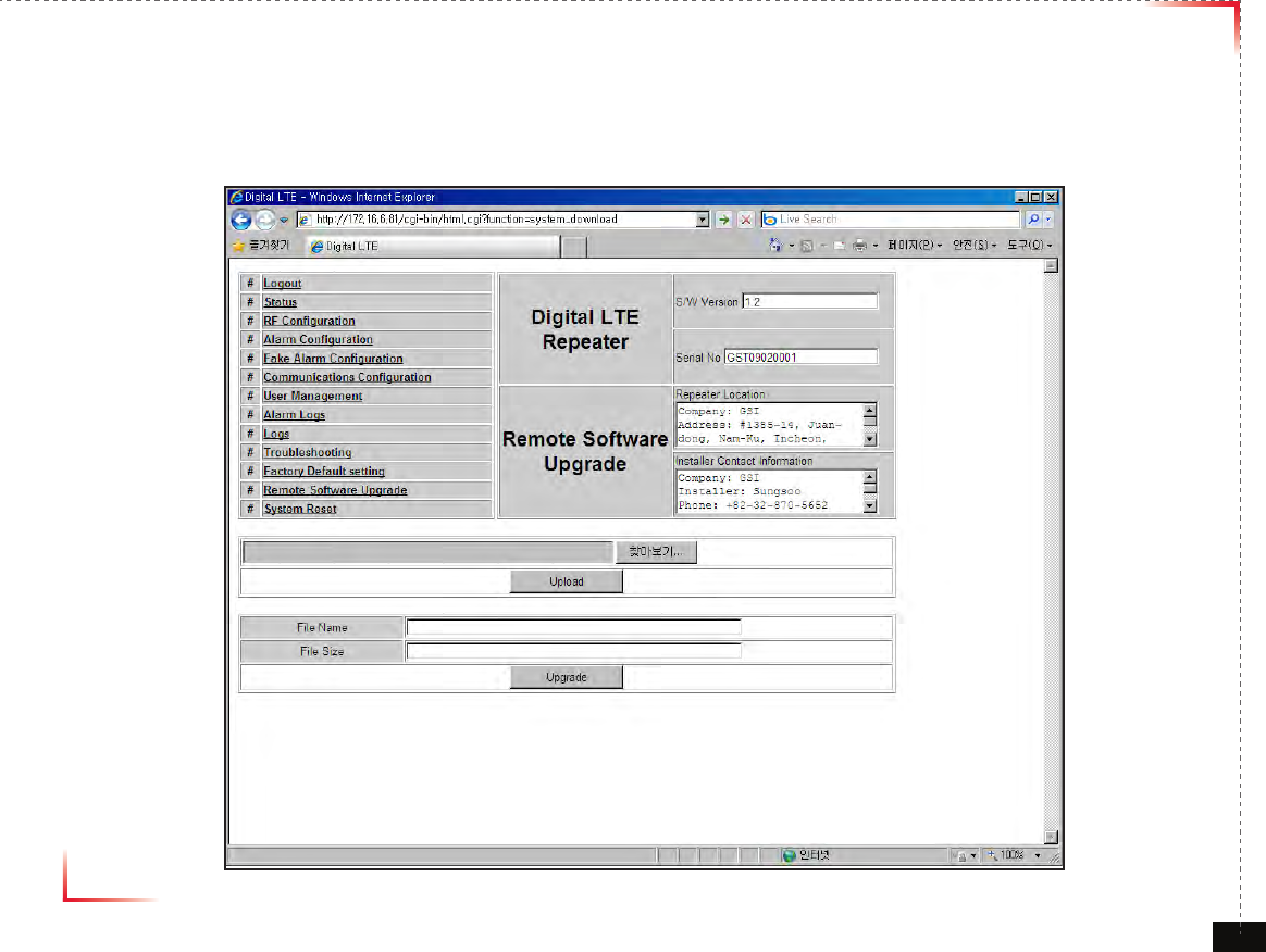
Software Upgrade
• Click on the Remote Software Upgrade link.
• In case that software upgrade is needed, you should use this page.
• Click Browse button to select the file to upgrade from the laptop.
Version 1.0 September 2010
© 2010, GS Teletech, Inc. 63
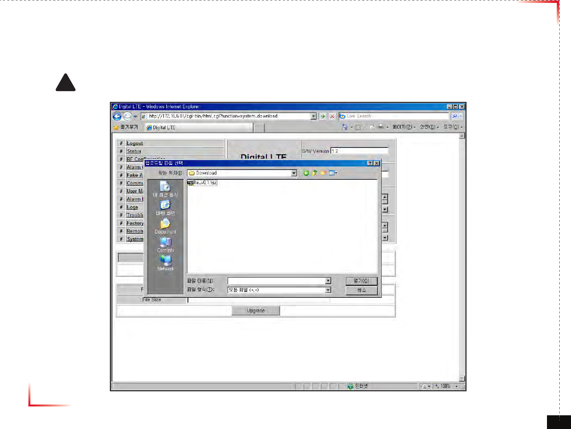
Software Upgrade
• Choose the le to upgrade provided by GST.
After you choose the le, you should click “upload” to send the le from your laptop to the repeater.
! CAUTION
Be careful not to unplug the crossover Ethernet cable during software upgrade.
Version 1.0 September 2010
© 2010, GS Teletech, Inc. 64
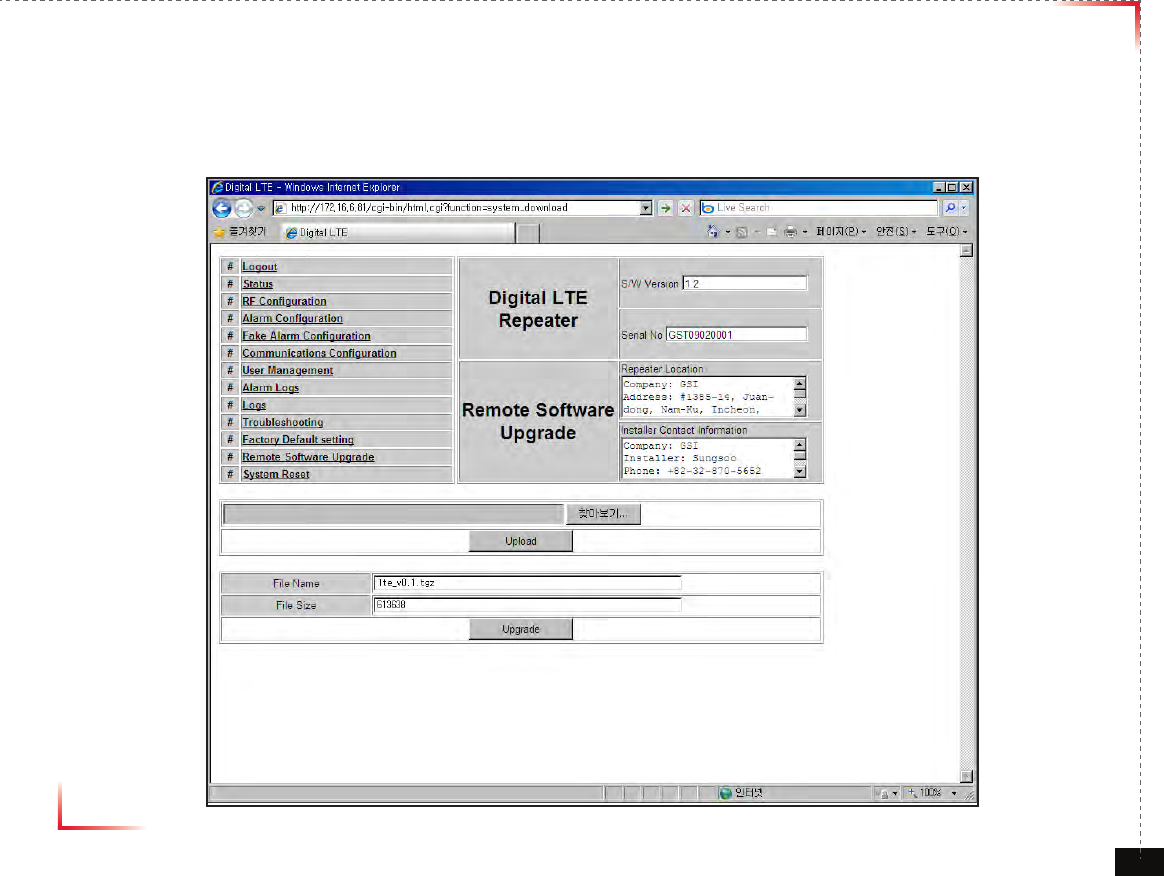
Software Upgrade
• After uploading is finished, verify that the File Name and the File Size is correct, click “Upgrade” button.
Installer should wait about 2 minutes for upgrade to initialize.
• User may then be prompted to log back into the Repeater.
Version 1.0 September 2010
© 2010, GS Teletech, Inc. 65
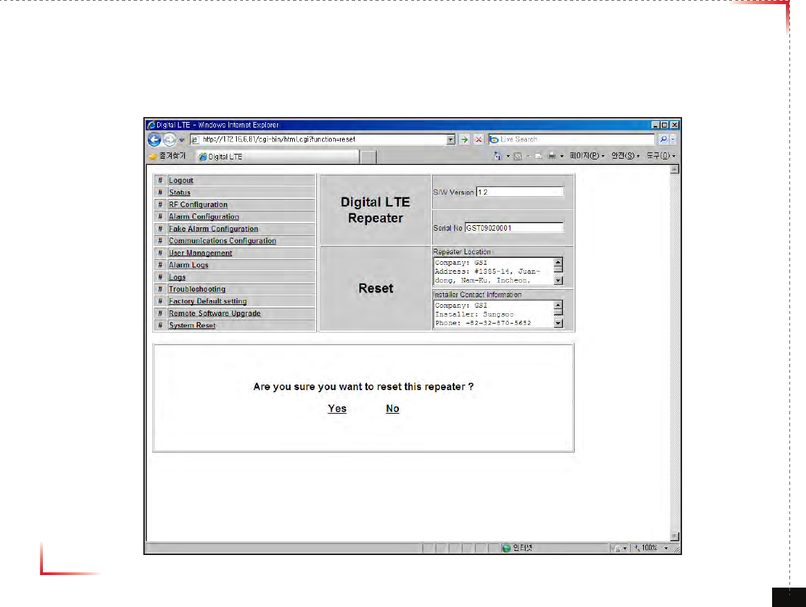
System Reset
• A software reset is a “soft reboot” of the repeater.
To reset the software, click on ‘Software Reset’ and then click ‘Yes’ to reset the software.
• Resetting the software is a good way to clear current alarms.
Version 1.0 September 2010
© 2010, GS Teletech, Inc. 66
GST Technical Support
Phone:
Toll Free: 1-866-9-GST-USA
Phone: 913-469-6699
Write:
GS Teletech Inc.
6900 College Boulevard, Suite 850
Overland Park, KS 66211, USA
Product Information and Technical Assistance:
www.gsteletechinc.com
support@gsteletechinc.com
Specifications and features of this installation guide are subject to change without notice or obligation.
Version 1.0 September 2010
© 2010, GS Teletech, Inc. 66
Warning: Exposure to Radio Frequency Radiation The radiated output power
of this device is far below the FCC radio frequency exposure limits.
Nevertheless, the device should be used in such a manner that the potential
for human contact during normal operation is minimized. In order to avoid
the possibility of exceeding the FCC radio frequency exposure limits, human
proximity to the antenna should not be less than 40cm during normal
operation. The gain of the antenna is 8 dBi. The antenna(s) used for this
transmitter must not be co-located or operating in conjunction with any other
antenna or transmitter.