GS Instech GRS-1915DC-SPR Repeater User Manual GRS 1915D SPR Manual 09 01 30
GS Instruments Co., Ltd. Repeater GRS 1915D SPR Manual 09 01 30
UserManual.wiki
>
GS Instech
>
GRS 1915DC SPR User Manual
Users Manual
Navigation menu
Upload a User Manual
Namespaces
Wiki Guide
HTML
PDF
Info
Views
User Manual
Discussion / Help
Navigation
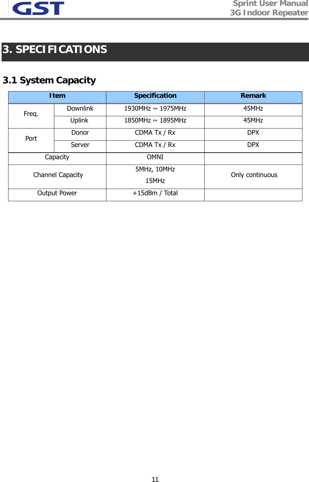
![Sprint User Manual 3G Indoor Repeater 10A1 A2 A3 DB1 B2 B3 E F1930 1935 1940 1945 1950 1955 1960 1965 1970 1975MHzA1 A2 A3 DB1 B2 B3 E F1850 1855 1860 1865 1870 1875 1880 1885 1890 1895MHz 2.2.3 Frequency Selection Downlink Frequency Table Uplink Frequency Table <Pic.6 > 1900MHz Band Structure PCS 1900 repeater has 5MHz, 10MHz, 15MHz Paths in IF division, so any of these bandwidths can be selected for providing service. 5MHz, 10MHz, 15MHz are only continious bands. But there are some cases when this choice is not applicable: - Not continuous 3 Paths [5 MHz each], so total band is 15MHz Ex) A1, D, E - Not continuous 3 Paths [5 MHz each], so total band is 10MHz Ex) A1, D - Not continuous 3 Paths [5 MHz and 10M ], so total band is 15MHz Ex) A1,A2,E](https://usermanual.wiki/GS-Instech/GRS-1915DC-SPR/User-Guide-1130373-Page-10.png)