GS Instech GRS-TRIR-SPR Digital TRI User Manual ATT E
GS Instruments Co., Ltd. Digital TRI ATT E
user manual

FCC ID : U88-GRS-TRIR-SPR
HCT CO., LTD.
SAN 136-1, AMI-RI, BUBAL-EUP, ICHEON-SI, KYOUNGKI-DO, 467-701, KOREA
TEL:+82 31 639 8517 FAX:+82 31 639 8525 www.hct.co.kr
Report No. : HCTR1010FR02 1/1
ATTACHMENT E.
- USER MANUAL -

Sprint User Manual
Digital TRI-Band Indoor Repeater
1
/
22
3G Indoor Repeater
GRS-TRIR-SPR
User Manual
AUGUST , 2010
Version 0.1

Sprint User Manual
Digital TRI-Band Indoor Repeater
2
/
22
- INDEX -
1. SUMMARY................................................................................... 3
2. SYSTEM CONFIGURATION ......................................................... 4
2.1 GRS-TRIR-SPR Service Organization.........................................................4
2.2 System Design and Operation....................................................................5
3. SPECIFICATIONS ..................................................................... 14
3.1 System Specifications(Applicable to both Uplink & Downlink)..오류! 책갈피
가 정의되어 있지 않습니다.
3.2 Electrical and Environmental Specifications............................................14
3.3 Functions .................................................................................................16
4. SET UP...................................................................................... 18
4.1 System Set up..........................................................................................18

Sprint User Manual
Digital TRI-Band Indoor Repeater
3
/
22
1. SUMMARY
GRS-TRIR-SPR is an Digital RF repeater, which iDEN 800/900 and US PCS Band Service. This
system has 90dB gain in the iDEN 800/900 band and PCS band respectively with 25dBm and
24dBm maximum power each
GRS-TRIR-SPR receives RF signal from BTS and transmits it to the blanked and shadowed area,
thus providing and improving voice and image data services. GRS-TRIR-SPR’s goal is to support
BTS’s functions proportionately.
GRS-TRIR-SPR communicates with BTS wirelessly, thus saving additional costs for its
maintenance.
GRS-TRIR-SPR consists of RF/IF part Module, PA Module, Wave Module, Digital Filter module,
and I/O & Control module divisions, which are supplied with Alarm LED, thus providing quick
and easy maintenance and troubleshooting of the repeater.
This manual describes in general structure of GRS-TRIR-SPR, its application, maintenance and
troubleshooting, installation and operation etc.
This equipment is indoor use and all the communication wirings are limited to inside of the
building.
CAUTION
RISK OF EXPLOSION IF BATTERY IS REPLACED BY AN IN CORRECT TYPE.
DISPOSE OF USED BATTERIES ACCORDING TO THE INSTRUCTIONS
Abbreviation
PCS : Personal Communication System
RF: Radio Frequency
BTS: Base Transceiver Station
IF: Intermediate Frequency
I/O : Input/Output
Sprint User Manual
Digital TRI-Band Indoor Repeater
4
/
22
2. System Configuration
2.1 GRS-TRIR-SPR Service Organization
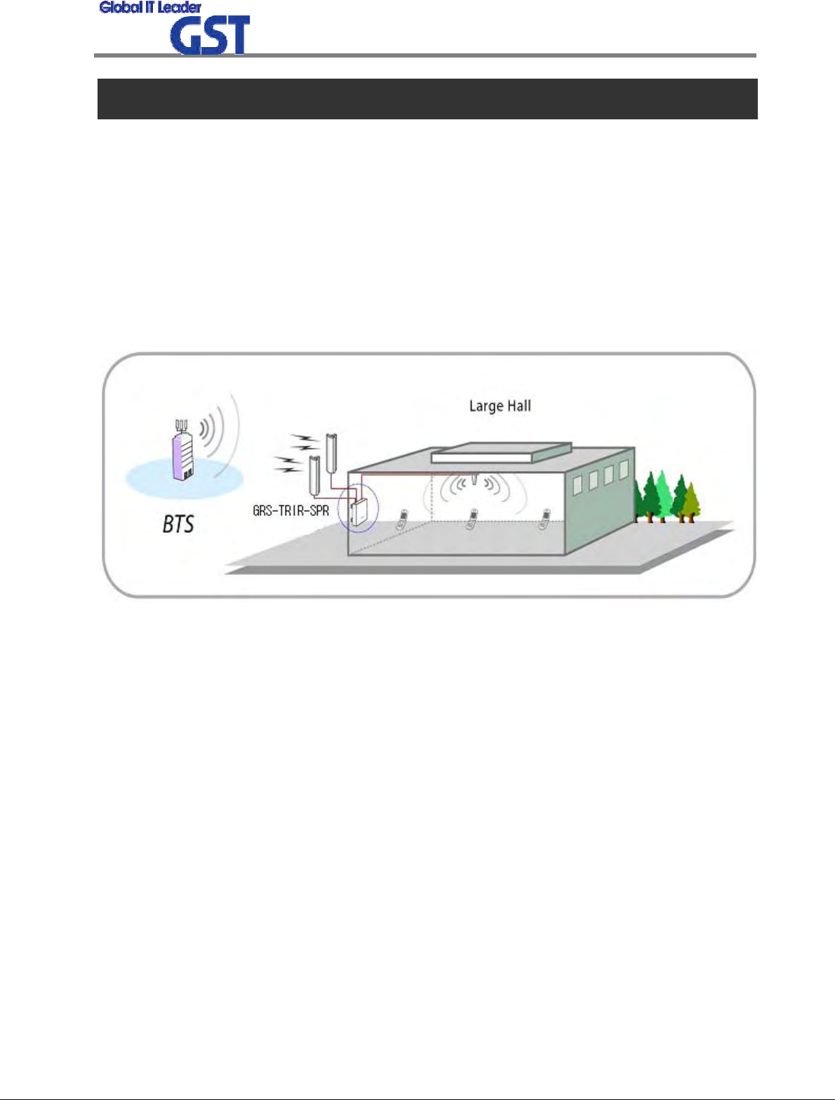
GRS-TRIR-SPR decreases blanked and shadowed areas and extend cell coverage by re-transmitt
ing signal. The signal is received from BTS via Antenna directly, thus excluding additional expen
ses for signal transmission (like cabling). Service organization of TRI Band(iDEN 800,900 and C
DMA) In-building RF repeater is shown at the picture below. Donor Antenna is directed to BTS
and being divided at Service Antennas are installed in the building and parking place. Pass Loss
should be taken into consideration while dividing and cabling.
<Pic.1> US PCS and iDEN 800/900 Service Organization
Sprint User Manual
Digital TRI-Band Indoor Repeater
5
/
22
2.2 System Design and Operation
2.2.1 System Design
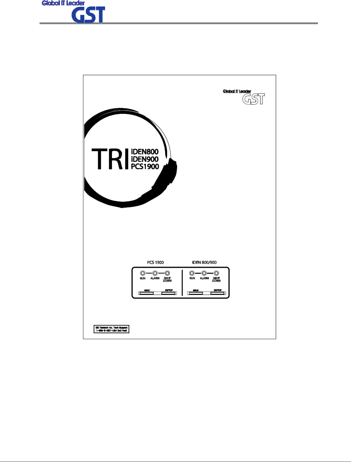
<Pic.2> GRS-TRIR-SPR Repeater
Sprint User Manual
Digital TRI-Band Indoor Repeater
6
/
22
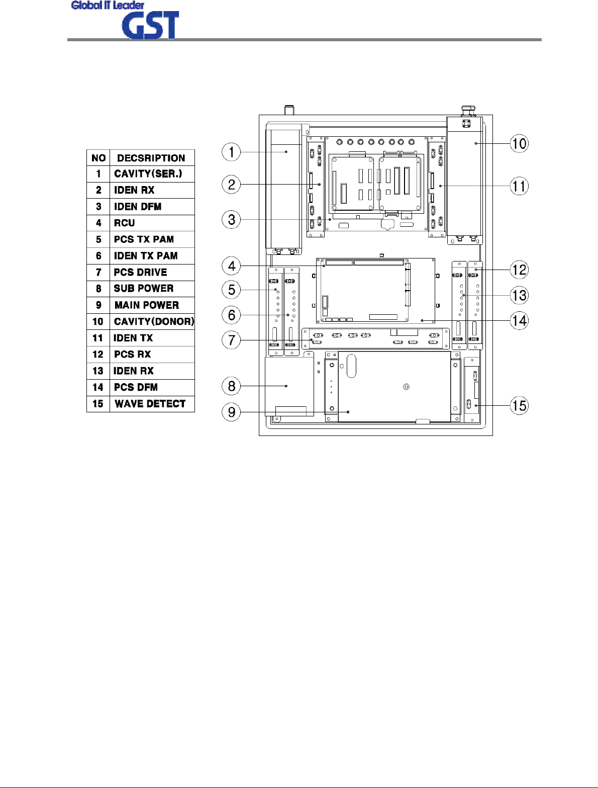
<Pic.3> Internal Design
Sprint User Manual
Digital TRI-Band Indoor Repeater
7
/
22
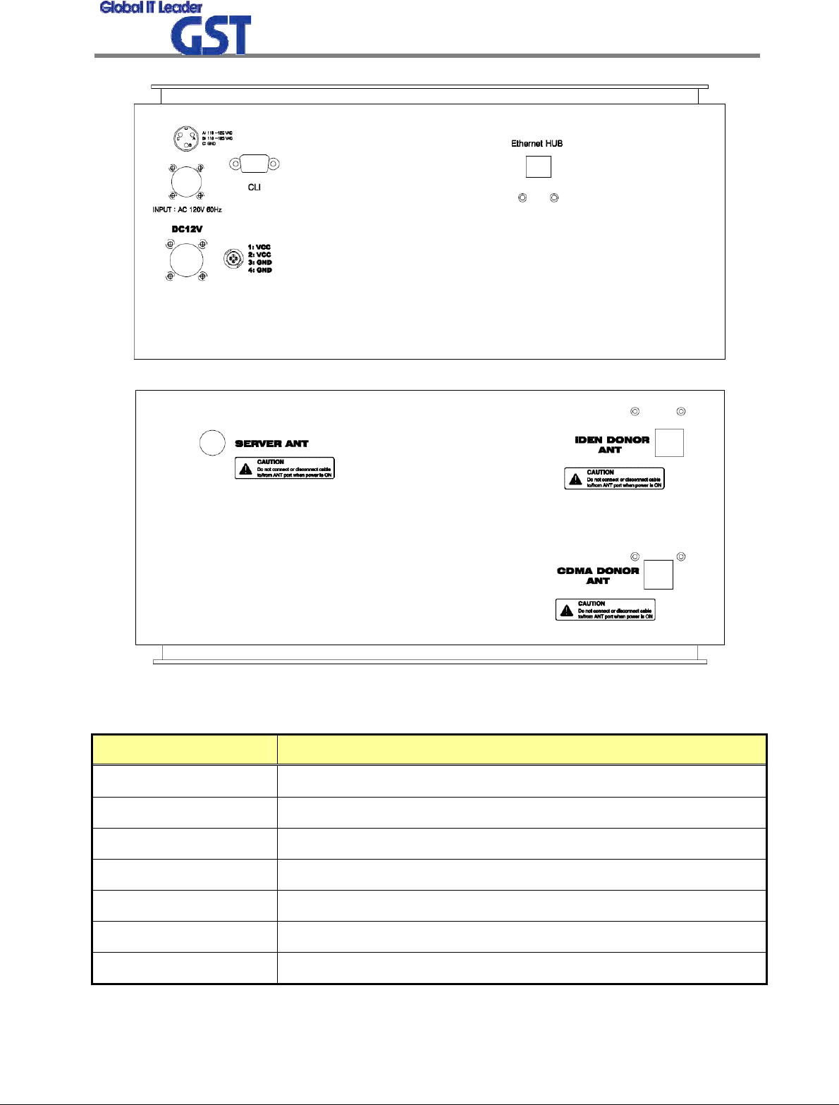
<Pic.4> Outside Port Design
NO DESCRIPTION
① SERVER ANT PORT
② iDEN DONOR ANT PORT
③ PCS DONOR ANT PORT
④ AC POWER PORT
⑤ DC 12V PORT
⑥ CLI MONITOR PORT
⑦ ETHERNET PORT
①②
③
④
⑤
⑥ ⑦
Sprint User Manual
Digital TRI-Band Indoor Repeater
8
/
22
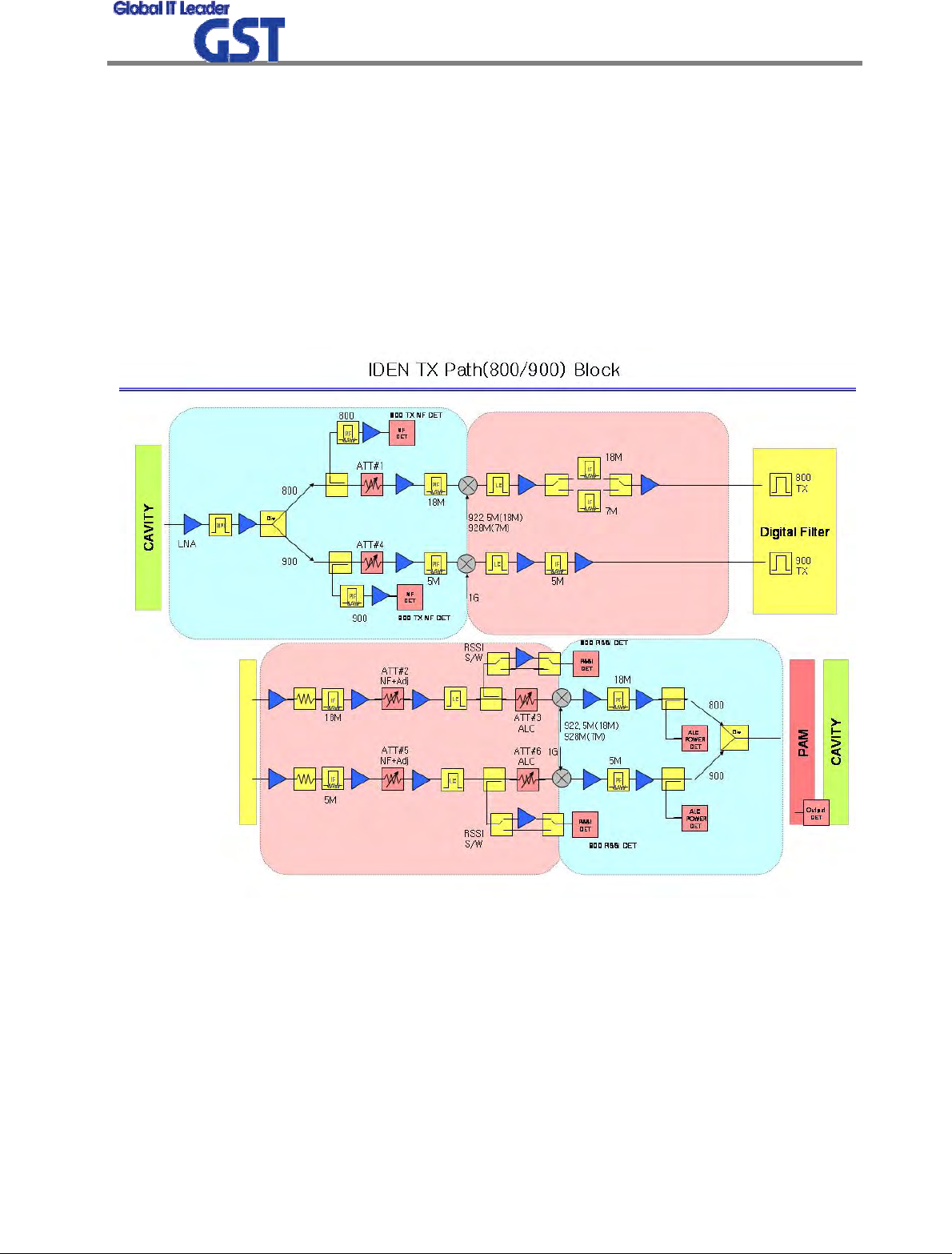
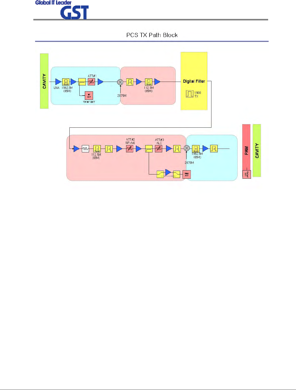
2.2.2 Downlink Path
Downlink and Uplink Gain Budgets have similar structure.
In case of Downlink Path, RF signal is received from Donor Antenna, and through FWD division,
then the signal is transferred to IF division, where desirable Band is selected by Digital Filter.
Selected Band is transferred to RF division again, and through FWD HPA, after that the signal is
transmitted to User through Server Antenna.
CDMA is used two attenuators for AGC compensation. AGC attenuation range of CDMA is 40dB.
AGC attenuation range of iDEN 800/900 is 30dB.
Sprint User Manual
Digital TRI-Band Indoor Repeater
9
/
22
<Pic.5> Downlink Block Diagram
Sprint User Manual
Digital TRI-Band Indoor Repeater
10
/
22
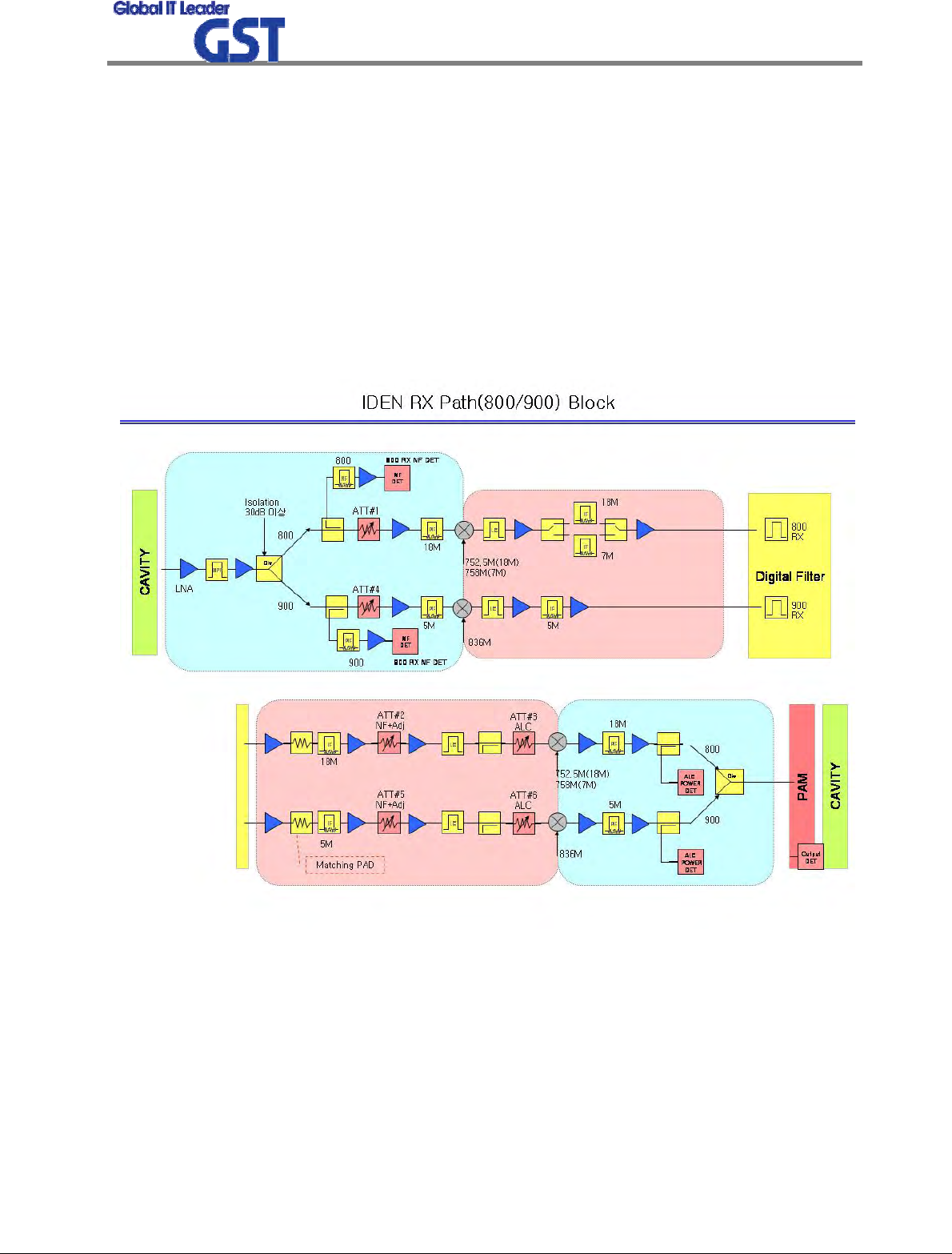
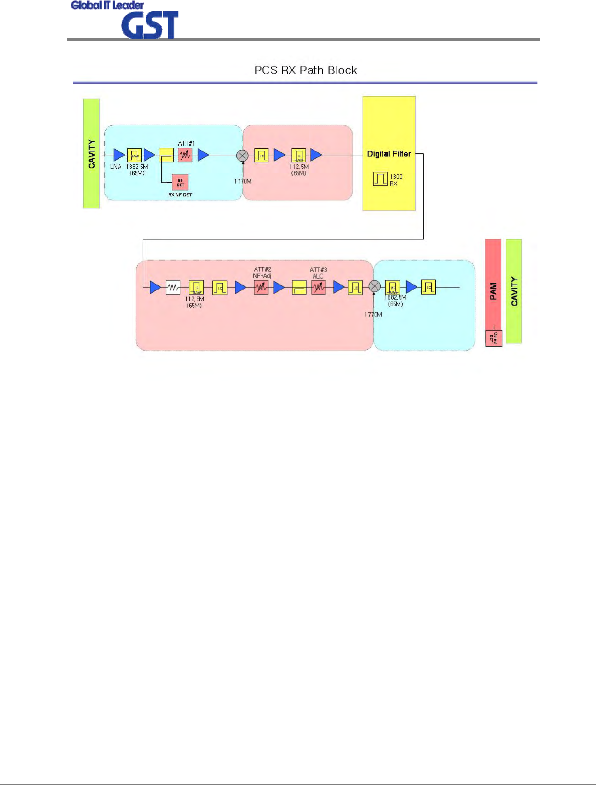
2.2.3 Uplink Path
Uplink Path is similar in structure to Downlink Path.
In case of Uplink Path, RF signal is received from Server Antenna, and through RVS division,
then the signal is transferred to IF division, where desirable Band is selected by Digital Filter.
Selected Band is transferred to RF division again, and through RVS HPA, after that the signal is
transmitted to BTS through Donor Antenna.
CDMA is used two attenuators for AGC compensation. AGC attenuation range of CDMA is 40dB.
AGC attenuation range of iDEN 800/900 is 30dB.
Sprint User Manual
Digital TRI-Band Indoor Repeater
11
/
22
<Pic.6> Uplink Block Diagram
Sprint User Manual
Digital TRI-Band Indoor Repeater
12
/
22
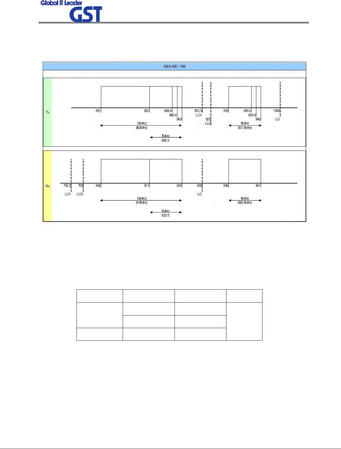
2.2.4 Frequency Selection
<IDEN 800/900 BAND>
GRS-TRIR-SPR IDEN800 BAND has 18MHz, 7MHz Paths in IF division, so any of these bandwidt
hs can be chosen for providing service.
Also, by adding Channel Select Function, it enables users to select band offset sophisticatedly.
iDEN 800/900 Band can changed bandwidth to 4MHz at 200kHz step of right band edge.
Max bandwidth Min Bandwidth Step
18M 4M
iDEN 800
7M 4M
iDEN 900 5M 4M
200kHz
Sprint User Manual
Digital TRI-Band Indoor Repeater
13
/
22
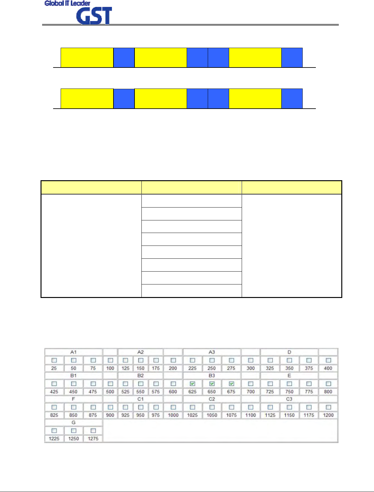
<US PCS BAND>
1930
AB CDEF G
1945 1950 1965 1970 1975 1990 1995
< Forward Band Structure >
f (MHz)
1930
AB CDEF G
1945 1950 1965 1970 1975 1990 1995
< Forward Band Structure >
f (MHz)
1850
AB CDEF G
1865 1870 1885 1890 1895 1910 1915 f (MHz)
< Reverse Band Structure >
1850
AB CDEF G
1865 1870 1885 1890 1895 1910 1915 f (MHz)
< Reverse Band Structure >
<Pic.7> 1900MHz PCS Band Structure
GRS-TRIR-SPR CDMA BAND has 5MHz, 10MHz, 15MHz, 20MHz Paths in IF division, so any of th
ese bandwidths can be chosen for providing service.
ITEM BANDWIDTH NOTE
5MHz
10MHz
15MHz
20MHz
5MHz + 5MHz
5MHz + 5MHz + 5MHz
10MHz + 5MHz
Band Select
15MHz + 5MHz
Any of these bandwidths from
A to G can be chosen
Also, by adding Channel Select Function, it enables users to select bands sophisticatedly. Each b
and has 1.25 MHz Bandwidth and if users select all the 15 bands, GRS-TRIR-SPR can serve 18.7
5MHz bandwidth to users.
Sprint User Manual
Digital TRI-Band Indoor Repeater
14
/
22
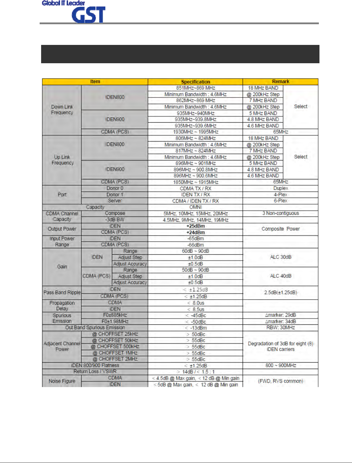
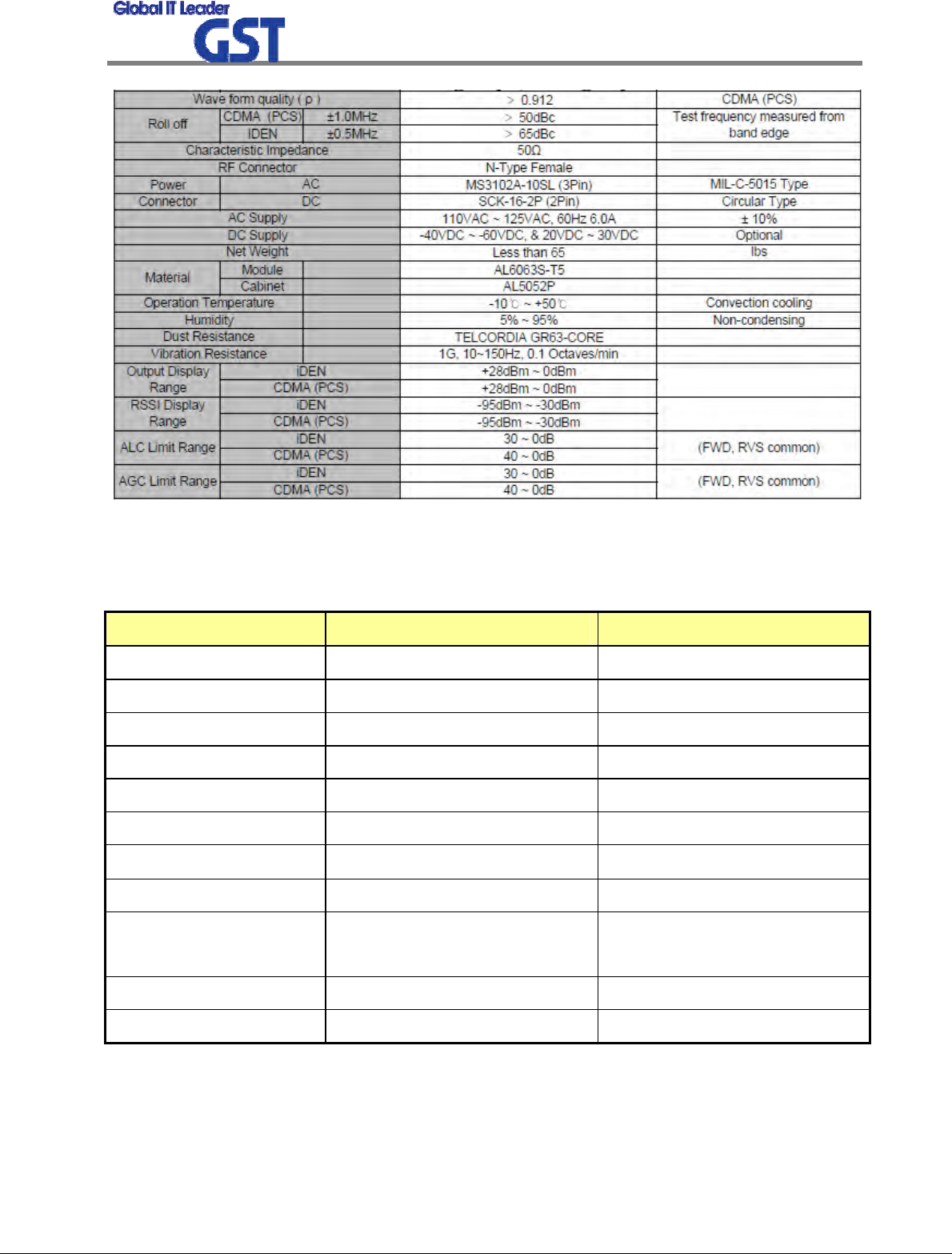
3. SPECIFICATIONS
3.1 System Specifications(Applicable to both Uplink & Downlink)
Sprint User Manual
Digital TRI-Band Indoor Repeater
15
/
22
3.2 Electrical and Environmental Specifications
ITEM SPECIFICATION REMARK
Power & Consumption 120 VAC 60Hz
Connector Type N-type female
Size 393 X 540 X 225
Weight max 65 lbs
Reliability, MTBF 100,000 hours
Enclosure NEMA4
Operating Temperature -10℃ ~ +50℃
Rel. Humidity 0% ~ 90%
Industry Standards TIA-97, TIA-98, IS-98D,
IS-2000
Regulatory Approvals FCC, Part24 CDN-IC
Safety Approvals UL1950 or Equiv

Sprint User Manual
Digital TRI-Band Indoor Repeater
16
/
22
3.3 Functions
ITEM FUNCTIONS
Gain Control
• Adjustable DL and UL Gain range 50~90dB(PCS)
• Adjustable DL and UL Gain range 60~90dB(iDEN800/900)
• Display default Gain and current Gain function
AGC
(Auto Gain Control)
• It always operates in Downlink AGC ON status
• To maintain same Downlink output power despite flexible input signal
strength
• To add or subtract Attenuation level referring to AGC Power Limit level.
• Used with the Automatic Setup (Auto Gain Setting)
ALC
(Auto Level Control)
• To limit output power as far as default range
• Used for DAS configuration and when oscillation/isolation is a concern
• Automatic Gain decrement when output power of repeater is higher
than default level
• Automatic Gain recovery when output power of repeater is reduced
• Shutdown when output power is higher than default level in Minimum
Gain
• Automatic Recovery Algorithm conversion after Shutdown status
AGS
(Auto Gain Setting)
• Operate when User control (Only system initialize)
• Decrease attenuator value for 3dB from minimum gain
• In case of attenuator value is from 0dB to 3dB when AGS ended
- AGC on (DL)
- Gain balance on
- PAM on
- Shutdown on
• In case of attenuator value is over 3dB when AGS ended
- AGC off (ALC on)
- Gain balance on
- PAM on
- Shutdown on
Gain Balance • Downlink ATT is applied to Uplink during AGC state

Sprint User Manual
Digital TRI-Band Indoor Repeater
17
/
22
• Setting and maintenance of output level
• Additional attenuation to ALC Level
Band Select • To select either 5MHz/10MHz/15MHz/20MHz (PCS)
• To select either 18MHz/7MHz (IDEN 800)
Power Monitoring
Function • Monitoring repeater’s output level
DL Input control • Monitoring Donor ANT input power of DL
Automatic Recovery • When repeater is shutdown, it periodically recovers output power of
repeater then monitors alarming
Security • Support HTTPS for Web Browser security
• User authentication through User ID and Password
Temperature
Monitoring
• Monitoring temperature of repeater
• Maximum and minimum set up is possible
• Shutdown in over temperature
• Automatic recovery after temperature becomes normal (Hysteresis 10
degree)
VSWR Monitoring • Monitoring VSWR of Donor ANT Port (Every one and half minute)
• Reporting VSWR Alarm and Shutdown when the rate is 3.5:1
IP address report via
E-mail
• When in PPP reconnection, E-mail which includes HTML to connect to
newly assigned IP Address, reports to operator.
DHCP Client • Automatic IP assignment
DHCP Server • Server function for automatic IP assignment
Web GUI • Remote and local user browser support through Web Browser
SNMP Agent • NMS report via SNMPv2 Trap
LED Display
• LED displays power and operation status on front side of repeater
system
• Input and Output signal levels are verified by LED bars
Sprint User Manual
Digital TRI-Band Indoor Repeater
18
/
22
4. SET UP
4.1 System Set up
4.1.1 Constitution (Based on 1 set)
PARAMETER ITEM QUANTITY
Major Accessory GRS-TIRI-SPR 1 EA
Additional Components
Main power input cable
Fixable screw
Mountable brackets
1 EA
1 SET
1 EA
User Manual Manual 1 EA
4.1.2 Notice
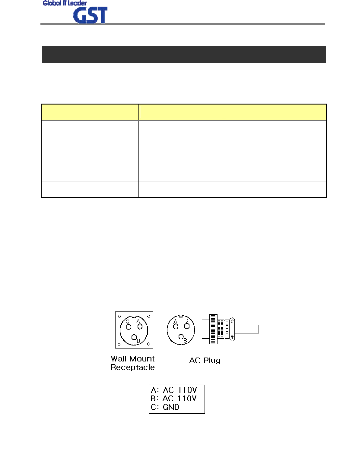
1) System Power check: Major electricity is AC110V, therefore please input electricity after
power verification.
2) Input condition optimization: DL input condition is -60 ~ -30dBm. User should verify
input condition of Donor ANT.
3) Isolation check between DONOR/SERVER ANT: Isolation condition of this equipment
is 97dBc (Gain+7dB). User should check its condition before installation.
<Pic.8> MS 3100 A 10SL-3 (Wall Mount Receptacle) & MS3010 A 10SL-3(Plug)
Sprint User Manual
Digital TRI-Band Indoor Repeater
19
/
22
CAUTION
DOUBLE POLE/NEUTRAL FUSING
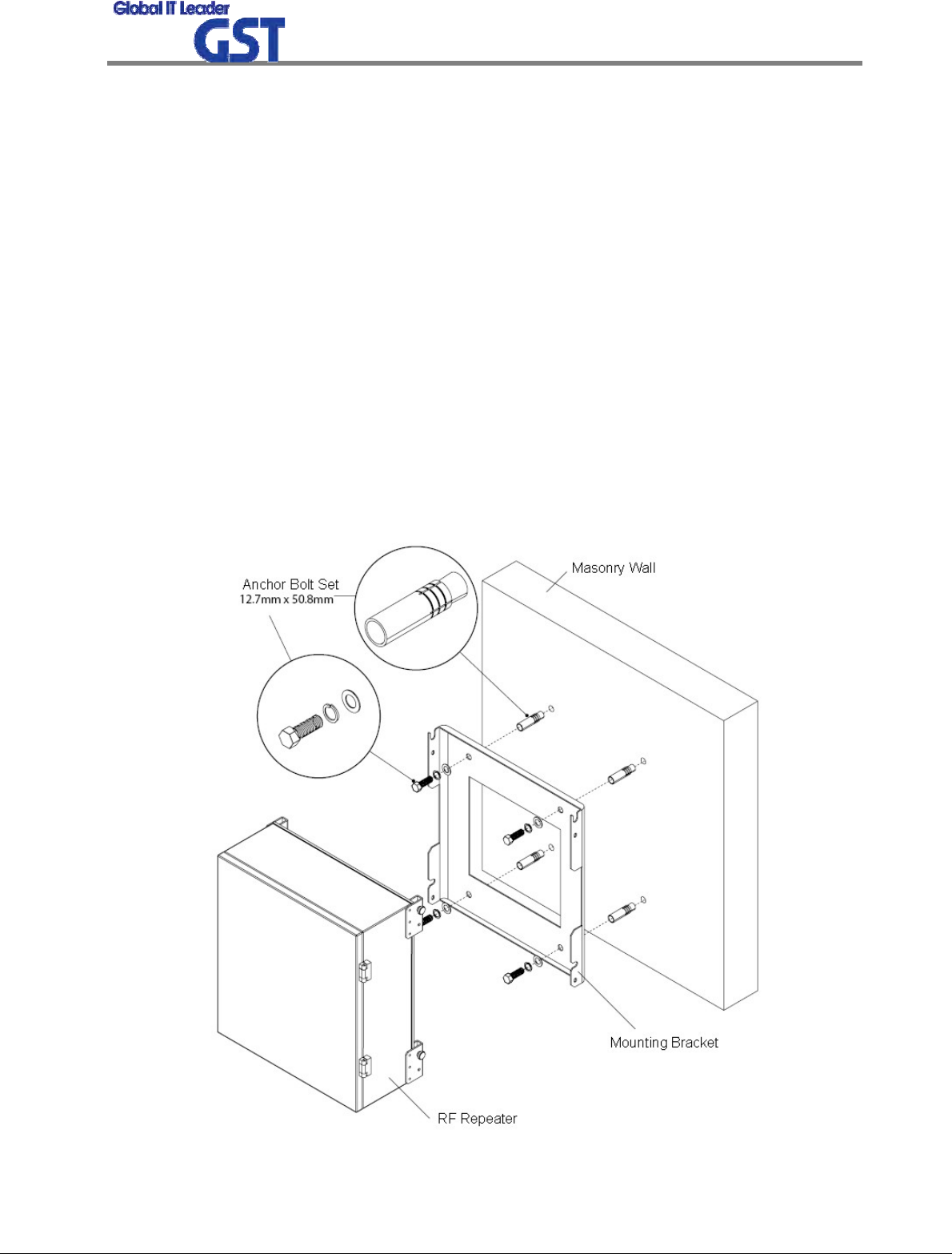
4.1.3 System Set up
1) This equipment is basically wall mountable installation.
2) Once aforementioned process is done, open for service get ready.
3) For grounding, there is a grounding terminal in main power supply side and the grounding
terminal on a site and unit should be connected same.
4) System installation work is basically performed more than two people and should be careful
for unexpected accident.
5) The socket-outlet shall be installed near the equipment and shall be easily accessible.
6) Round terminals located on the side of a 0.75 mm2 (18 AWG) or more wires Using
permanently connected to earth.
<Pic.9> Case Mounts - Step 1
Sprint User Manual
Digital TRI-Band Indoor Repeater
20
/
22
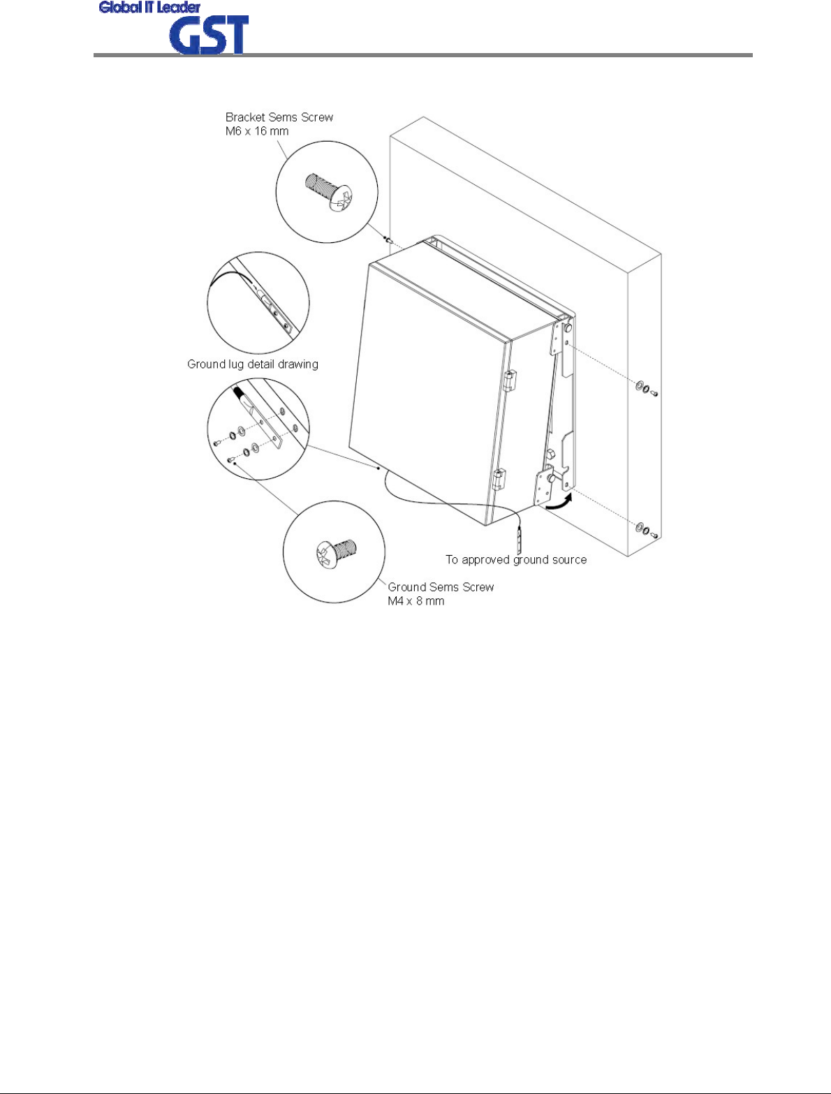
<Pic.10> Case Mounts - Step 2
4.1.4 Open for Service
1) Check points before open
a. Verification of system installation status
- Electricity, In/out antenna, coaxial cable connection, and equipment mounts status.
b. Verification of system accessories
- User should check whole necessary accessories.
c. Check receipt signal level
- User should check whether receipt environmental condition is in accordance with system
specification, so that system operation will be optimized.
2) Check points after open
a. Check by external LED
Sprint User Manual
Digital TRI-Band Indoor Repeater
21
/
22
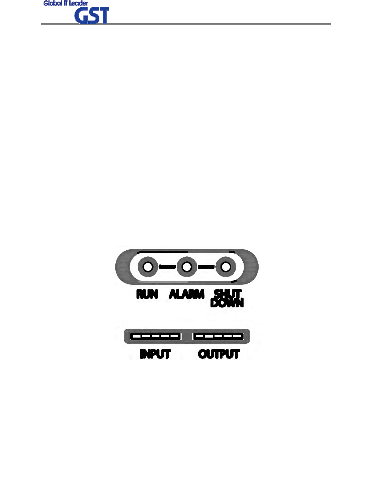
① RUN: Green light ON (Off: Green light off)
② ALARM: Green light in normal status, Red light in alarming
③ SHUT DOWN: Green light in normal status, Red light in Shutdown status
④ Number of LED bar on front side of repeater will show input power signal level
Less than -86dBm: LED 1 bar
-85dBm ~ -70dBm: LED 2 bar
-69dBm ~ -54dBm: LED 3 bar
-53dBm ~ -41dBm: LED 4 bar
More than -40dBm: LED 5 bar
⑤ Number of LED bar on front side of repeater will show output power signal level
Less than +9dBm: LED 1 bar
+10dBm ~ +14dBm: LED 2 bar
+15dBm ~ +19dBm: LED 3 bar
+20dBm ~ +24dBm: LED 4 bar
More than +25dBm: LED 5 bar
<Pic.11> Front LED
b. Verification of operation status
- User should verify following status with Output monitoring terminal, which is provided by
Spectrum Analyzer
- Output power generation status, system spurious emission characteristics.

Sprint User Manual
Digital TRI-Band Indoor Repeater
22
/
22
c. Verification of signal quality and strength in service area
- User should verify signal strength and quality of in-service coverage area by using cell
phone or other measuring device.
d. Verification of upper-level NMS operation status

MPE Information
ⓒ SAMSUNG Electronics Co., Ltd.
Warning: Exposure to Radio Frequency Radiation The radiated output power
of this device is far below the FCC radio frequency exposure limits.
Nevertheless, the device should be used in such a manner that the potential
for human contact during normal operation is minimized. In order to avoid
the possibility of exceeding the FCC radio frequency exposure limits, human
proximity to the antenna should not be less than 30cm during normal
operation. The gain of the antenna is 12 dBi. The antenna(s) used for this
transmitter must not be co-located or operating in conjunction with any other
antenna or transmitter.