GS Instech GSTR-830DC-SPR iDEN In-Building Repeater User Manual Manual
GS Instruments Co., Ltd. iDEN In-Building Repeater Manual
Manual
SPRINT User Manual
iDEN_30dBm
February, 2007

SPRINT User Manual
iDEN 30dBm
2
INFORMATION TO USER :
NOTE: This equipment has been tested and found to comply with the limits for a Class A digital
device, pursuant to Part 15 of the FCC Rules. These limits are designed to provide reasonable
protection against harmful interference when the equipment is operated in a commercial
environment. This equipment generates, uses, and can radiate radio frequency energy and, if
not installed and used in accordance with the instruction manual, may cause harmful
interference to radio communications. Operation of this equipment in a residential area is likely
to cause harmful interference in which case the user will be required to correct the interference
at his own expense.
CAUTION
Changes or modifications not expressly approved
by the manufacturer responsible for compliance
could void the user's authority to operate the equipment

SPRINT User Manual
iDEN 30dBm
3
- INDEX -
1. SUMMARY .................................................................................................................4
2. SYSTEM STRUCTURE...............................................................................................5
2.1 Network structure for iDEN 30dBm RF Repeater.............................................................................................5
2.2 System Design and Operation..............................................................................................................................6
3. SPECIFICATIONS...................................................................................................11
3.1 System specifications........................................................................................................................................... 11
3.2 Electrical and Environment Specifications.......................................................................................................12
3.3 Functions..............................................................................................................................................................12
4. SET UP .....................................................................................................................14
4.1 System Set up.......................................................................................................................................................14
4.2 Troubleshooting...................................................................................................................................................17
c. When in trouble shooting, technician should use attenuator to check output side..........................................17
5. WEB USER INTERFACE .........................................................................................18
5.2 Web UI .................................................................................................................................................................19
5.3 Web UI control ....................................................................................................................................................20

SPRINT User Manual
iDEN 30dBm
4
1. SUMMARY
iDEN repeater is located in blanket / shadow area of insider of building to transmit
iDEN800MHz, iDEN900MHz BTS signal simultaneously.
There are two types of RF Repeater for iDEN band as each 15dBm, and 25dBm output power
in system 65dB Gain, and 30dBm output power in system 80dB Gain.
This User Manual is the Repeater having 65dBGain / +25dBm output power.
Bandwidth
- Downlink 851MHz~869MHz, Uplink 806MHz~824MHz (18MHz Band)
- Downlink 862MHz~869MHz, Uplink 817MHz~824MHz (7MHz Band)
To avoid paging signal interference at 940MHz side, IF Converter shift SAW filter edge by
200KHz, 400KHz. (TX Edge only, not whole bandwidth).
Also, This Repeater is equipped for Output power control by AGC/ALC, Gain Control by
Attenuator adjustment, Remote Control by using Web UI and Remote Firmware Up-grade.
Abbreviation
PAM: POWER AMPLIFIER MODULE
LNA: LOW NOISE AMPLIFIER
AGC: AUTO GAIN CONTROL
ALC: AUTO LIMIT CONTROL
SPRINT User Manual
iDEN 30dBm
5
2. SYSTEM STRUCTURE
2.1 Network structure for iDEN 30dBm RF Repeater
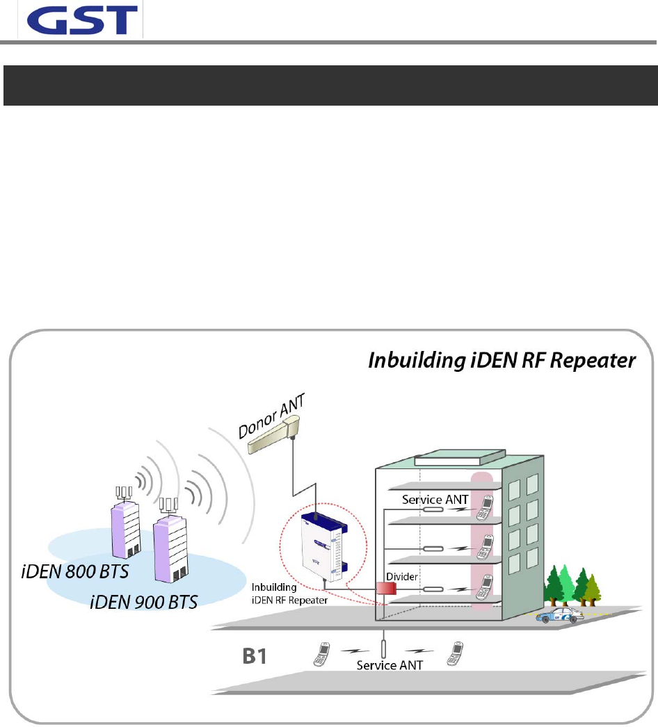
Below picture shows a Network structure for iDEN In-building RF Repeater in a real site. Donor
ANT takes a position on the direction to BTS which be linked, and Server ANT is available to be
located in designated area for service by using RF cable deployments and dividers as blow.
One thing that we consider is Path losses between Repeater port and ANT in case of dividing by
dividers and RF cables. They should be equally managed.
<Pic.1> iDEN In-building Repeater Service Organization
SPRINT User Manual
iDEN 30dBm
6
2.2 System Design and Operation
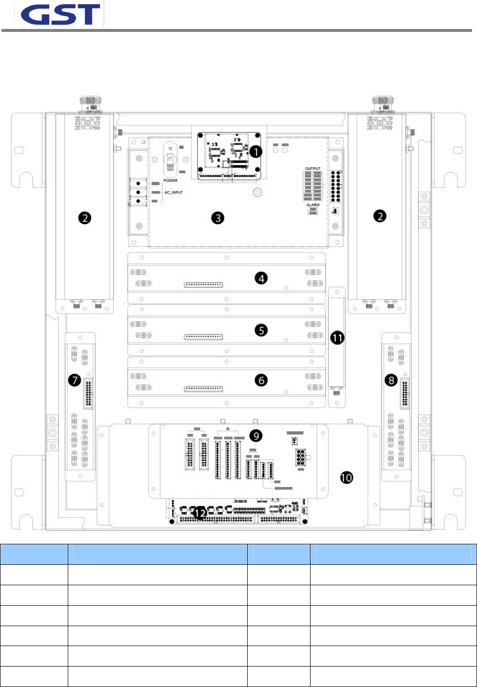
2.2.1 System design
NO. PART NO. PART
① MODEM MODULE ⑦ RVS LAN MODULE
② CAVITY FILTER MODULE ⑧ FWD LAN MODULE
③ PSU MODULE ⑨ I’O BOARD MODULE
④ 7M IF CONVERTER MODULE ⑩ POWER AMPLIFIER MODULE
⑤ 18M IF CONVERTER MODULE ⑪ WAVE MONITORING MODULE
⑥ 5M IF CONVERTER MODULE ⑫ NMS MODULE
<Pic.2> iDEN 30dBm internal design
SPRINT User Manual
iDEN 30dBm
7
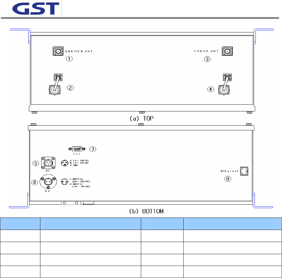
NO. PORT NO. PORT
① SERVICE ANT PORT ⑤ AC POWER PORT
② SERVICE ANT TERM ⑥ DC POWER PORT
③ DONOR ANT PORT ⑦ MONITOR PORT
④ DONOR ANT TERM ⑧ ETHERNET PORT
<Pic.3> iDEN 30dBm PORT design
2.2.2 Downlink Path
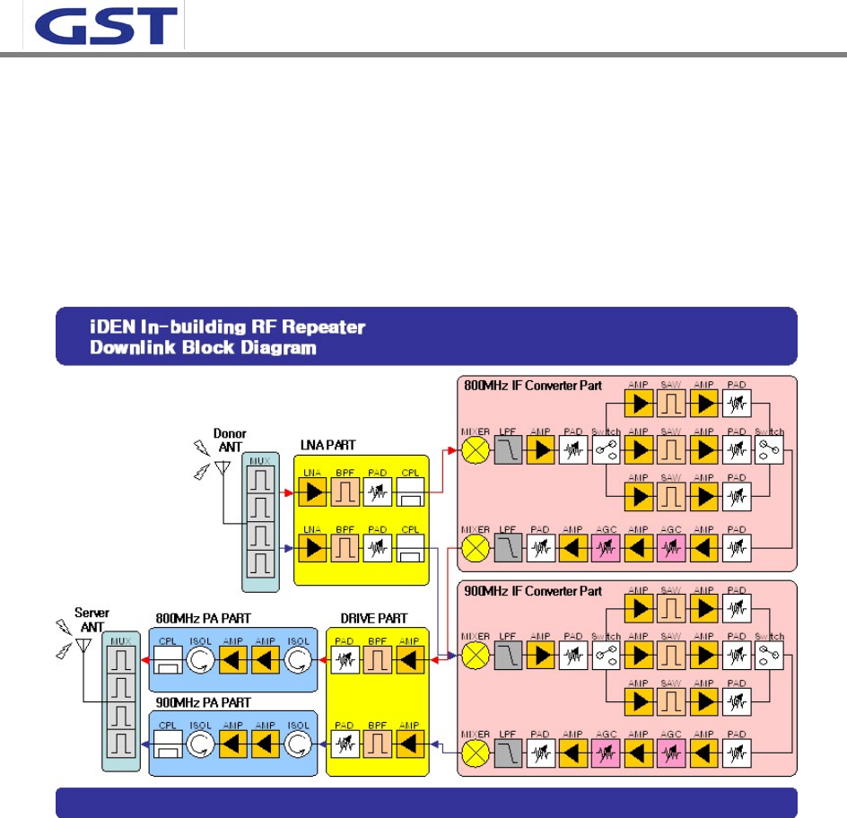
There are four (4) parts of downlink Block in iDEN In-building RF Repeater.
- Filter part for Multiplex four (4) bands as each 800MHz and 900MHz TX/RX in Front End
of Donor/Server
- LNA part of Donor/Service path to process signals of 800MHz and 900MHz bands.
- If Converter part having several bands of SAW Filter paths to adjust Band Edge of high
frequency as 200KHz and 400KHz each. In case of 800MHz band, extra Switching Filters
equipped to individually select 18MHz and 7MHz
SPRINT User Manual
iDEN 30dBm
8
- Power Amplifier part for power amplifier and Level Monitoring/VSWR monitoring to
adjust desirable output power of Repeater
Downlink frequency contains lots of signals such as Paging signal, DCS etc through Donor ANT.
So Out band signals should be minimized by SAW filters having excellent Roll off characteristics
for the best optimized operation.
<Pic.4> iDEN In-building RF Repeater Downlink Block Diagram
2.2.3 Uplink Path
Uplink Block of iDEN In-building RF Repeater is separated as four (4) parts.
- Filter part for Multiplex four (4) bands as each 800MHz and 900MHz TX/RX in Front End
of Donor/Server
- LNA Part of two(2) paths for processing 800MHz and 900MHz signals
- 800MHz IF Converter part and 900MHz IF Converter part of 5MHz band having Switching
filter parts for selecting each 18MHz and 7MHz.
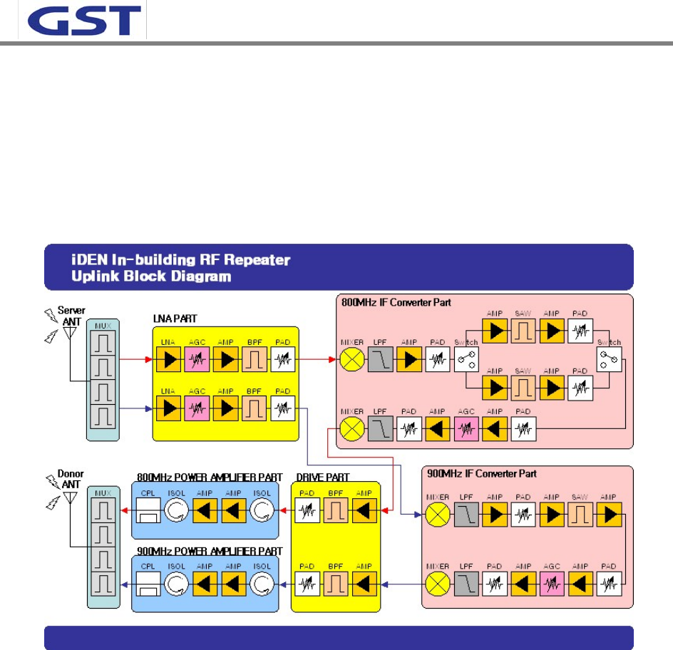
SPRINT User Manual
iDEN 30dBm
9
- Power Amplifier part for power amplifier and Level Monitoring/VSWR monitoring to
adjust desirable output power of Repeater
800MHz IF Converter part is designed to select single path, and it can be minimizing signal
interference between paths, and power consumption according to controls of electric power in
each SAW Filter part.
<Pic.5> iDEN In-building RF Repeater Uplink Block Diagram
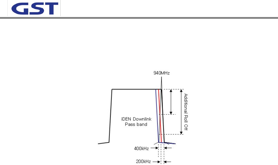
2.2.4 Adjustable Band Edge functional circuit configuration
In case of IDEN using the bandwidth of 800MHz and 900MHz, many of Out of Band Signals is
input via Donor ANT Outdoor. The most worried signal among them is Paging Signal.
Commercial Paging Signal of 929MHz~932MHz, 940MHz~941MHz, having the strength of Max.
-15dBm, is to be inputted into Donor ANT. Among this two kind of Paging Signal Band,
929MHz~932MHz bandwidth is possible for sufficient Rejection via SAW Filter, But
940MHz~941MHz is difficult to gain big decreasing volume even if use SAW Filter because Band
Edge is as close as to be folded to 935MHz~940MHz of being the frequency of iDEN900MHz
Downlink.
To prepare for this environment, Down Link of iDEN Repeater is designed to have additional
SPRINT User Manual
iDEN 30dBm
10
Roll Off characteristic by decreasing band of SAW Filter in the station adjacent to paging signal,
for it having the function of Adjust Band Edge that can decrease c of high frequency by 200 kHz,
400 kHz each.
<Pic.6> Additional Roll off through Adjust Band Edge
SPRINT User Manual
iDEN 30dBm
11
3. SPECIFICATIONS
3.1 System specifications
Characteristic Specification
18 MHz BAND 851~869 MHz
17.8 MHz BAND 851~868.8 MHz
17.6 MHz BAND 851~868.6MHz
7 MHz BAND 862~869 MHz
6.8 MHz BAND 862~868.8 MHz
800MHz
6.6 MHz BAND 862~868.6MHz
5 MHz BAND 935~940MHz
4.8 MHz BAND 935~939.8MHz
Forward
900MHz
4.6 MHz BAND 935~939.6MHz
18 MHz BAND 806~824 MHz
800MHz 7 MHz BAND 817~824 MHz
Frequency Range
Reverse
900MHz 5 MHz BAND 896~901 MHz
System Group Delay < 8 ㎲
Characteristic Impedance 50 ohm
VSWR Max.1.5 : 1
Input Power Range -53 ~ -25dBm (FWD, RVS common)
Gain Range 55dB ~ 80dB
Noise Figure < 5 dB @ Max Gain
<12 dB @Min Gain
Gain Adjustment Step(Accuracy) 1dB(±0.5dB)
Pass Band Ripple 2.5dB(±1.25dB)
Maximum Output Power 1000mW / 30dBm @ Composite Power
800MHz:27dBm, 900 MHz:27dBm
Spurious Emissions <-13dBm
IF Frequency FWD: 70 MHz, RVS: 70 MHz
@CH offset 25 KHz > 50 dBm
@ Degradation of 3dB for eight iDEN carriers
@CH offset 50 KHz > 55 dBm
@ Degradation of 3dB for eight iDEN carriers
@CH offset 500 KHz > 55 dBm
@ Degradation of 3dB for eight iDEN carriers
Adjacent
Channel
Power
@CH offset 1MHz > 55 dBm
@ Degradation of 3dB for eight iDEN carriers
SPRINT User Manual
iDEN 30dBm
12
@CH offset 2 MHz > 55 dBm
@ Degradation of 3dB for eight iDEN carriers
@ 869 MHz 868.8MHz/868.6MHz Adjust
Band Edge @ 940 MHz 939.8MHz/939.6MHz
Band Select Local Shift & RF Switching
Roll Offs > 50dBc
3.2 Electrical and Environment Specifications
Items specification
Size(mm) / Type 16(W)*18(L)*7(H) / Inch
Power AC 120V 60Hz 3.0A
Temperature / Weight 0℃ ~ +50℃/20.6kg
Connector TYPE N Type Female
3.3 Functions
Parameter Specification
Gain Control • Adjustable DL and UL Gain range 55~80dB
• Display default Gain and current Gain function
AGC
Auto Gain Control
• It always operates in Downlink AGC ON status
• To maintain same Downlink output power despite flexible input signal
strength.
• To add or subtract Attenuation level referring to AGC Power Limit level.
ALC
Auto Limit Control
• To limit output power as far as default range
• Set up via GUI
• Automatic Gain decrement when output power of repeater is higher than
default level
• Automatic Gain recovery when output power of repeater is reduced.
• Shutdown when output power is higher than default level in Minimum Gain
• Automatic Recovery Algorithm conversion after Shutdown status
Band Select
• In case of 800MHz FWD Band, it enables User to select one of 18MHz,
17.8MHz, 17.6MHz/ 7MHz, 6.8MHz, and 6.6MHz according to GUI setting.
• In case of 900MHz FWD Band, it enables User to select one of 5MHz,
4.8MHz, 4.6MHz according to GUI setting.
• In case of 800MHz RVS Band, it enables User to select one of 18MHz/
7MHz according to GUI setting.

SPRINT User Manual
iDEN 30dBm
13
• In case of 900MHz RVS Band, it enables User to select 5MHz according to
GUI setting.
Band Edge Adjust • To shift Band edge of DL high frequency side by 200kHz, 400kHz step
Power Monitoring
Function • Monitoring repeater’s output level
Oscillation Check
• Isolation Check in initial set up or Reset
• Monitoring Oscillation comparing to minimum/maximum Noise Floor level
• When Oscillation occurred, repeater attempts to stabilize Isolation through
Gain control function.
• Shutdown repeater when Oscillation still goes in Minimum Gain
• Automatic Recovery Algorithm conversion after Shutdown status
DL Input control • Monitoring Donor ANT input power of DL
Automatic Recovery • When in repeater shutdown, it periodically recovers output power of
repeater then monitors alarming
Security • Support HTTPS for Web Browser security
• User authentication through User ID and Password
Temperature
control
• Monitoring temperature of repeater
• Maximum and minimum set up is possible. Shutdown in over temperature
• Automatic recovery after temperature becomes normal. (Hysteresis
10degree)
VSWR Monitoring
• Monitoring VSWR of Donor ANT Port (Every one and half minute)
• Reporting VSWR Alarm and Shutdown when the rate is 3:1
• Automatic Recovery Algorithm conversion after Shutdown status
IP address report
via E-mail
• When in PPP reconnection, E-mail which includes HTML to connect to
newly assigned IP Address, reports to operator.
DHCP Client • Automatic IP assignment
DHCP Server • Server function for automatic IP assignment
Web GUI • Remote and local user browser support through Web Browser
SNMP Agent • NMS report via SNMPv2 Trap
LED Display • LED displays power and operation status on front side of repeater system.
• DL input and output signal level is verified by LED bar.
SPRINT User Manual
iDEN 30dBm
14
4. SET UP
4.1 System Set up
4.1.1 Constitution (based on 1 SET)
Parameter Item Quantity
Major accessory iDEN 30dBm repeater 1 EA
Additional components Main power input Cable
Mountable Bracket
Fixable Screw
1 EA
1 EA
1 SET
User Manual Manual 1 EA
4.1.2 Notice
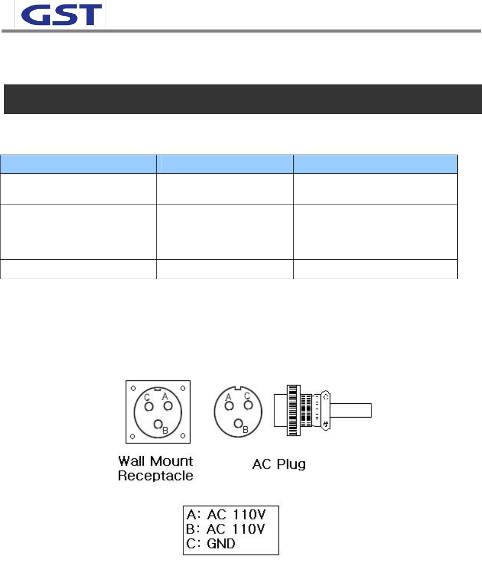
1) System Power check: Major electricity is AC110V, therefore please input electricity after power
verification.
<Pic.7> MS 3100 A 10SL-3 (Wall Mount Receptacle) & MS3010 A 10SL-3(Plug)
2) Input condition optimization: DL input condition of iDEN is -53 ~ -25dBm.
3) Isolation check between DONOR/SERVICE ANT: Isolation condition of this equipment is 95dBc (Gain+
15dB). User should check its condition before installation.
4) This equipment is basically wall mountable installation.
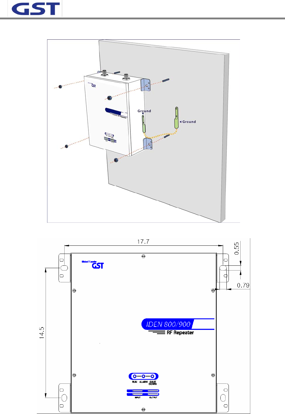
SPRINT User Manual
iDEN 30dBm
15
<Pic.8> Wall mounted iDEN In-building RF Repeater
<Pic.9> Hole sizes of iDEN In-building RF Repeater

SPRINT User Manual
iDEN 30dBm
16
4.1.3 System set up
1) Once aforementioned process is done, open for service get ready.
2) For grounding, there is a grounding terminal in main power supply side and the grounding
terminal on a site and unit should be connected same.
3) System installation work is basically performed more than two people and should be careful for
unexpected accident.
4.1.4 Open for service
1) Check points before open
a. Verification of system installation status
Electricity, In/out antenna, coaxial cable connection, equipment mounts status.
b. Verification of system accessories
User should check whole necessary accessories.
c. Check receipt signal level
User should check whether receipt environmental condition is in accordance with system specification,
so that system operation will be optimized.
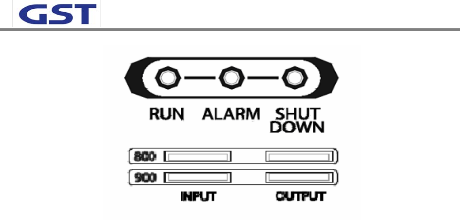
2) Check points after open
a. Check by external LED
RUN: Green light ON (Off: Green light off)①
ALARM: Green light in normal status, Red light in alarming②
SHUT DOWN: Green light in normal status, Red light in Shutdown ③
iDEN ④
Number of LED bar on front side of repeater will show input signal level.
-57dBm -47dBm: LED 1bar
-46dBm~-41dBm: LED 2 bars
-40dBm~-35dBm: LED 3 bars
-34dBm~-29dBm: LED 4 bars
Up than –28dBm: LED 5 bars
Number of LED bar in output power side will show output power signal level.
+5dBm~+9dBm: LED 1bar
+10dBm~+14dBm: LED 2bars
+15dBm~+19dBm: LED 3bars
+208dBm~+24dBm: LED 4bars
Up than +25dBm: LED 5bars
SPRINT User Manual
iDEN 30dBm
17
<Pic.10> iDEN In-building RF Repeater front LED
b. Verification via Debug Program
User should check operation status of repeater system via Debug Program.
c. Verification of operation status
Use should verify following status with Output monitoring terminal, which is provided by
Spectrum Analyzer.
- Output power generation status, system spurious emission characteristics.
d. Verification of signal quality and strength in service area
User should verify signal strength and quality of in-service coverage area by using cell phone or
other terminal.
e. Verification of upper-level NMS operation status
4.2 Troubleshooting
In case, abnormal operation is detected, user should check abnormal parts via remote accessible
function or field debug, then conduct repair after turn it off.
4.2.1 Necessary Testing and Measuring equipment
a. RF Power Meter: 10Watt Max, 50ohm
b. Signal Generator: 3GHz
c. Spectrum Analyzer: 3GHz
d. Multi Meter
4.2.2 Notice
a. Trouble shooting should be performed with drastic knowledge basis.
b. Unsure parts should not be disassembled.
c. When in trouble shooting, technician should use attenuator to check output side.
SPRINT User Manual
iDEN 30dBm
18
5. WEB USER INTERFACE
5.1 IP Address verification and Explorer setting
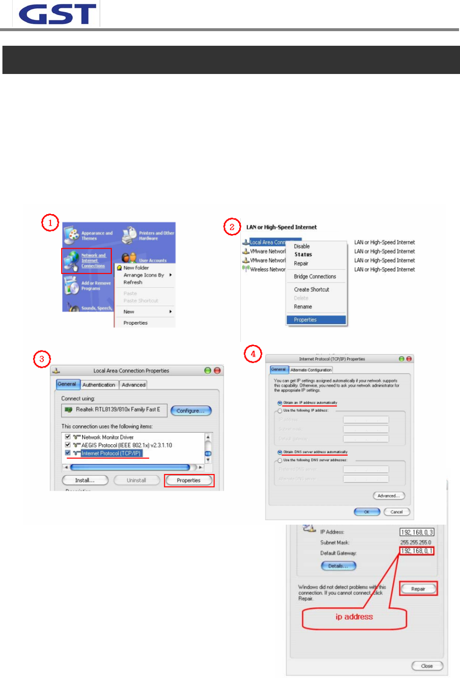
5.1.1 IP Address verification
(1) Start->Control Panel->Network Connections
(2) Double-click Local Area Connections at LAN or High Speed internet
(3) Click Internet Protocol (TCP/IP) at General tap and click Properties.
(4) Apply automatic IP address assignment at local connection
(5) Verify assigned IP address at local connection.
(Unless IP address is not assigned, please click
repair.)
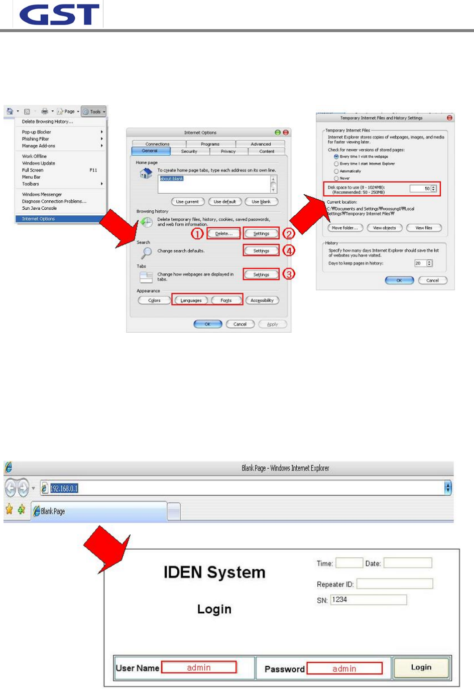
5.1.2 Explorer option setting
- Proceed step by step as indicated in below. All files
and records should be removed.
SPRINT User Manual
iDEN 30dBm
19
- Set up mode will be displayed after (2) click.
- Please proceed along following set up mode screen shot.
5.2 Web UI
5.2.1 Web UI connection
- Input desirable IP address.
- Default Use Name and Password for Web UI is ‘admin’.
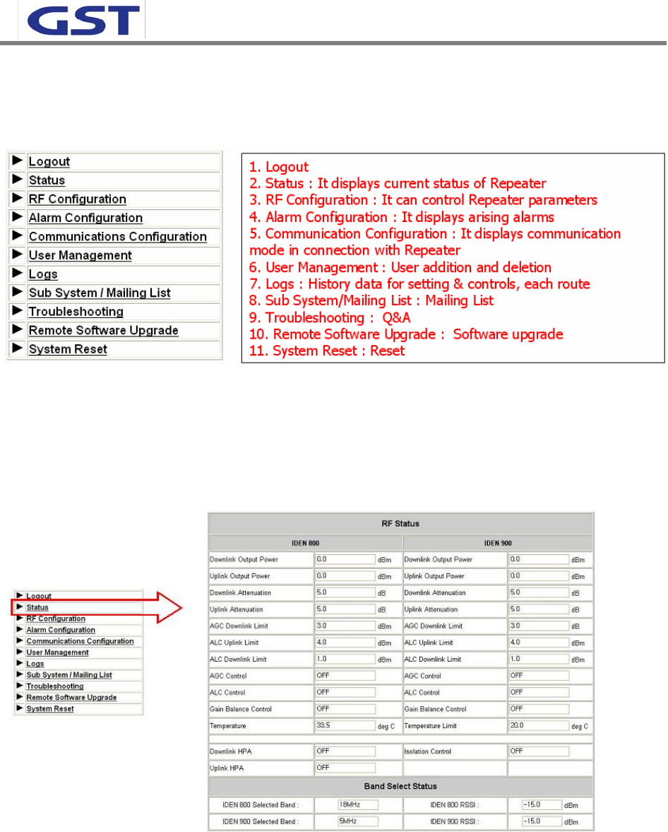
5.2.2 Link menu
SPRINT User Manual
iDEN 30dBm
20
- Following screen shot is located left-top side of main menu and those are linked to relative
window.
5.3 Web UI control
5.3.1 Status
- Currently setting level check at this menu tap.
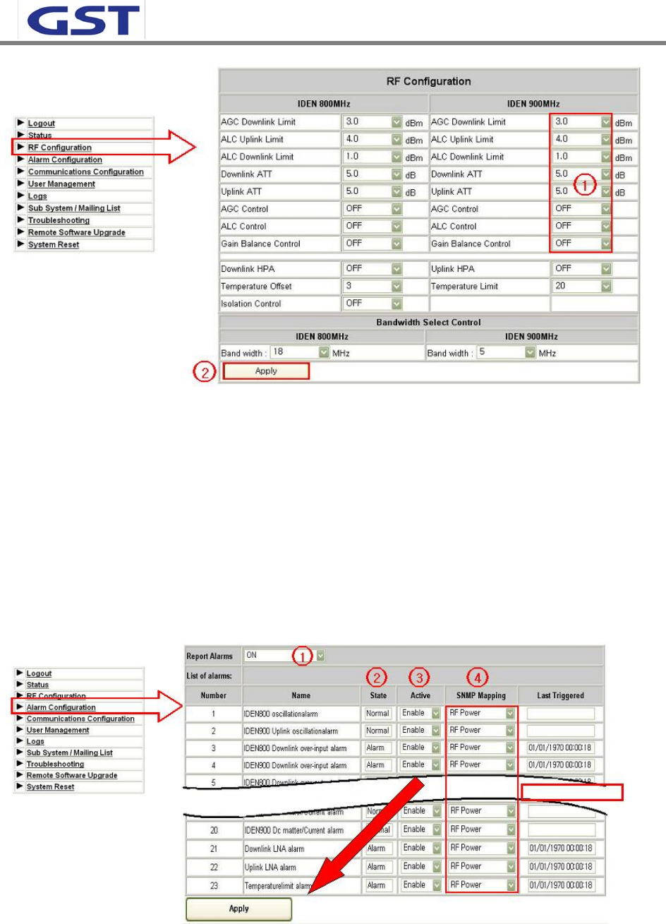
5.3.2 RF Configuration
- Setting level can be changed at this menu tap.
- (1) Level change
- (2) Click Apply button
SPRINT User Manual
iDEN 30dBm
21
5.3.3 Alarm Configuration
- (1) On/Off function for entire alarm report
- (2) Alarm status
- (3) On/Off function for individual alarm category
- (4) Alarm SNMP Mapping
- User may set and change its level per it field condition and click apply button.
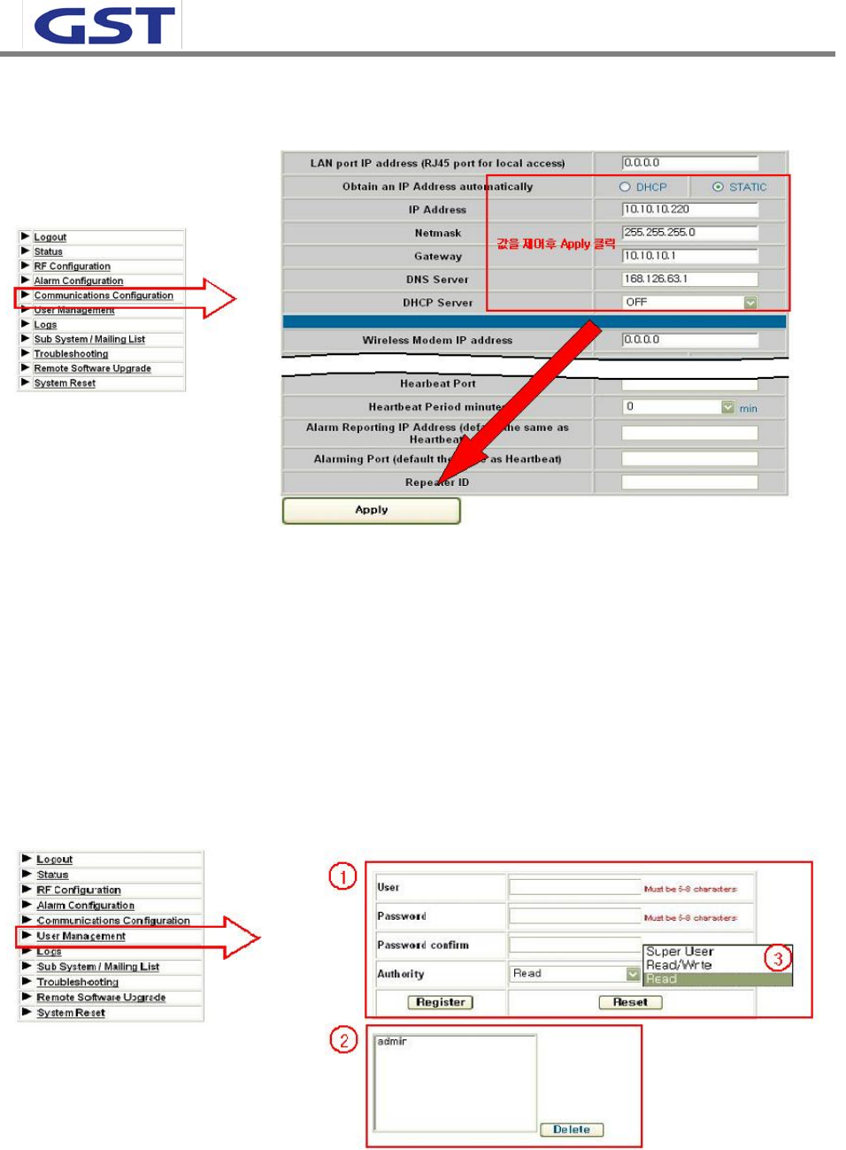
5.3.4 Communication Configuration
- This provides all necessary information related to network
SPRINT User Manual
iDEN 30dBm
22
- To provide relative information about DHCP and modem
5.3.5 User Management
- Add and Remove user, Assigning accessibility
- (1) User Registration: Click Register after input required information
- (2) User Removal: Click Delete upon click of user name you wish to remove.
- (3) Super User: Accessible to all kinds of information path
Read/Write: Accessible to all kinds of information path except for User management path.
Read: Checking status only. No control
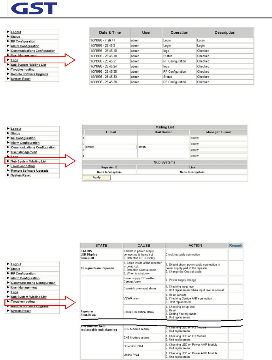
5.3.6 Logs
- All users’ access record will be saved as a log.
SPRINT User Manual
iDEN 30dBm
23
5.3.7 Sub System/Mailing List
- Set up e-mail address the place you wish to receive alarm.
5.3.8. Troubleshooting
Following is a trouble shooting table, which is frequently occurred to repeater and treatment me
thod.
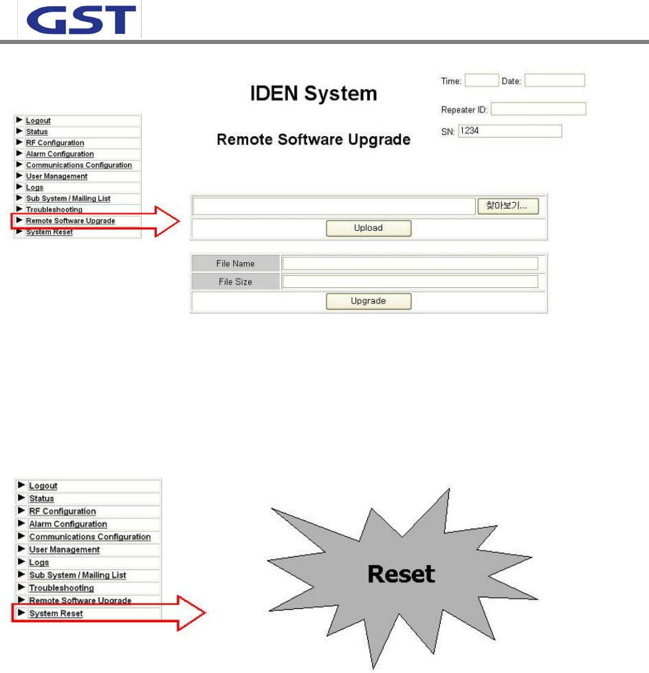
5.3.9 Remote Software Upgrade
- Upload repeater operation program.
SPRINT User Manual
iDEN 30dBm
24
5.3.10 System Reset
- Reset repeater.