GS Instech PSELITE78A Public Safety Repeater User Manual PS ELITE7833A Ver 1 0 rev 1
GS Instech Co., Ltd. Public Safety Repeater PS ELITE7833A Ver 1 0 rev 1
UserManual.wiki
>
GS Instech
>
PSELITE78A User Manual
PS-ELITE7833A_User Manual Ver 1.0_rev.1
Navigation menu
Upload a User Manual
Namespaces
Wiki Guide
HTML
PDF
Info
Views
User Manual
Discussion / Help
Navigation
![GSTeletech, Inc. 14 3. Specifications 3.1 US Frequency Allocation 3.1.1 US frequency Item Specification Remark Down Link Frequency 700 (PSBB) 758MHz ~ 768MHz LTE 700 (PSNB) 769MHz ~ 775MHz P25 800 (PSNB) 851MHz ~ 861MHz P25 Up Link Frequency 700 (PSBB) 788MHz ~ 798MHz LTE 700 (PSNB) 799MHz ~ 805MHz P25 800 (PSNB) 806MHz ~ 816MHz P25 3.1.2 US Block Diagram [MHz] Service Donor Antenna RFU DFM HPA Remarks Start Stop Start Stop Start Stop Start Stop DL 700 758 775 758 775 758 775 758 775 DL 800 851 861 851 861 851 861 851 861 UL 788 816 788 816 788 816 788 816 3.1.3 US Service Plan](https://usermanual.wiki/GS-Instech/PSELITE78A/User-Guide-3695796-Page-20.png)
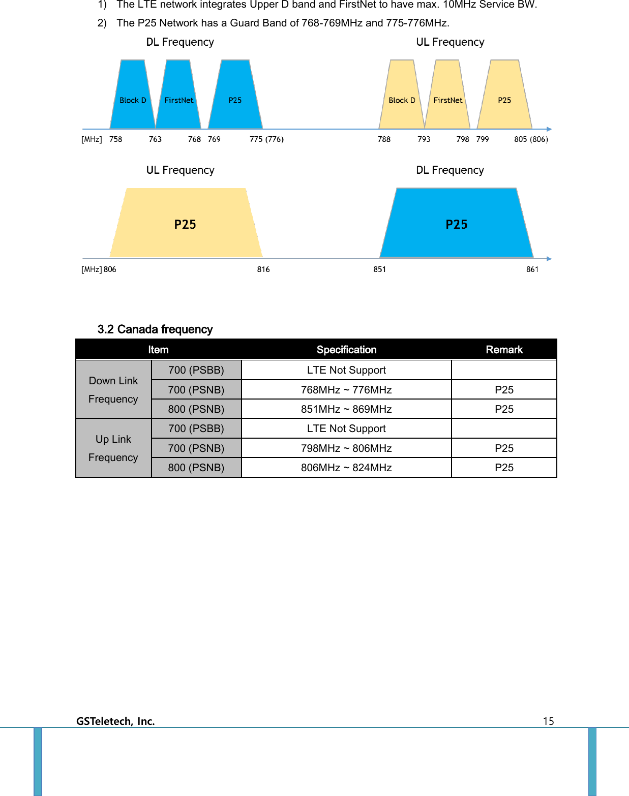
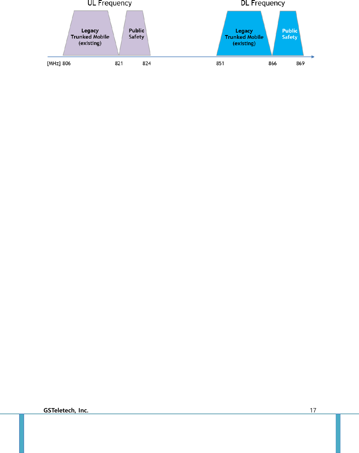
![GSTeletech, Inc. 16 3.2.1 Canada Block Diagram [MHz] Service Donor Antenna RFU DFM HPA Remarks Start Stop Start Stop Start Stop Start Stop DL 700 768 776 768 776 768 776 768 776 DL 800 851 869 851 869 851 869 851 869 UL 798 824 798 824 798 824 798 824 3.2.2 Canada Service Plan 1) Canada currently does not support LTE in the Public Services network. 2) Canadian 700MHz Public Safety band does not use Guard Band.](https://usermanual.wiki/GS-Instech/PSELITE78A/User-Guide-3695796-Page-22.png)