GS Instech SC-8930AMP In-Building RF Repeater User Manual 1
GS Instruments Co., Ltd. In-Building RF Repeater 1
User manual

SpeedCell Repeater
INSTALLATION GUIDE
Ver. 1.0
ntzT_`ZWhtwVkm|Tzwy

SpeedCell Repeater
ntzT_`ZWhtwVkm|Tzwy
Installation Guide Ver. 1.0

Contents of Box
Contents Picture Quantity Contents Picture Quantity
SpeedCell Repeater System
PSU Unit
4.3”(W) x 16.9”(H) x 10.7”(D) , 15 lbs
DFM Unit
2.8”(W) x 16.9”(H) x 10.7”(D), 9.9 lbs
800/900 AMP Unit
3.9”(W) x 16.9”(H) x 10.7”(D) , 19 lbs
1EA
Ground Cable
6.6ft (2m) 1EA
Power Cord
5.9ft (1.8m) 1EA
Ethernet Cable
6.6ft (2m) 1EA
Mounting Bracket
23.2”(W) x 18.5”(H) x 2.75”(D), 23.5 lbs 1EA Lag Screw
1/2” x 2” 4EA
CD which contains
- User Manual
- Installation Guide
1EA Ground Sems Screw
M4 x 8mm 4EA
RF Cable Set
Front RF Cable 2EA, Top RF Cable 4EA,
Reference Cable 3EA
1EA Mounting Sems Screw
M6 x 10mm 8EA
3
UL/FCC: This equipment complies with UL and FCC
This publication provides instruction for installing the SpeedCell repeaters.
The images for the User Interface in this publication may vary from the repeater’s depending on its S/W
Version.
Copyright
© 2011, GS Teletech, Inc.
All Rights Reserved
Printed in Republic of Korea
Revision History
Certification
Date
Version
Changes
03/2011
version 1.0
4
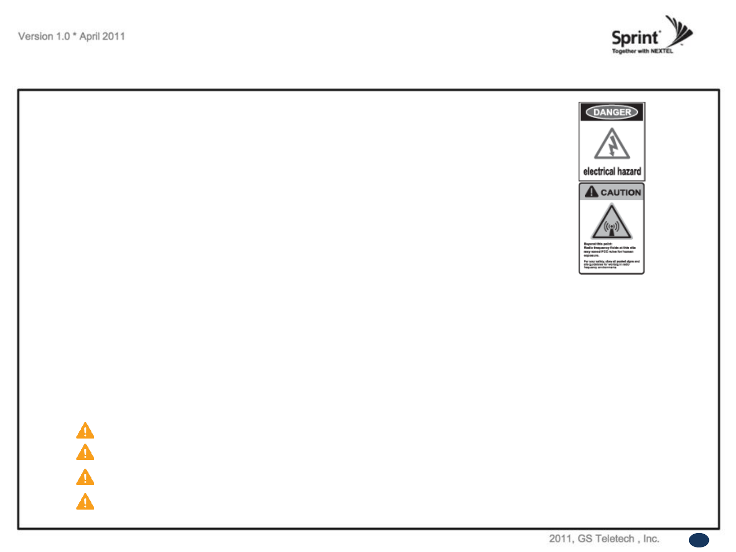
WARNING! EXPOSURE TO RF
Working with the repeater while in operation, may expose the technician to RF electromagnetic fields
that exceed FCC rules for human exposure. Visit the FCC website at http://www.fcc.gov/oet/rfsafety
to learn more about the effects of exposure to RF electromagnetic fields.
Warnings and Hazards
WARNING! ELECTRIC SHOCK
Opening the BDA (bi-directional amplifier) could result in electric shock and may cause severe injury.
WARNING! DAMAGE TO EQUIPMENT
Operating the BDA with antennas in very close proximity facing each other could lead to severe damage to the repeater.
RF EXPOSURE & ANTENNA PLACEMENT
Actual separation distance is determined upon gain of antenna used.
Please maintain a minimum safe distance of at least 8inch while operating near the donor and the server antennas. Also,
the donor antenna needs to be mounted outdoors on a permanent structure.
WARRANTY
Opening or tampering the BDA will void all warranties.
CAUTION: REPEATER SHOULD BE INSTALLED AS CLOSE AS POSSIBLE TO POWER SOURCE.
CAUTION: THIS REPEATER IS FOR INDOOR USE ONLY AND SHOULD BE LOCATED INSIDE OF BUILDING.
CAUTION: RISK OF EXPLOSION IF BATTERY ON CONTROLLER BOARD IS REPLACED WITH AN INCORRECT TYPE.
CAUTION: DISPOSE OF USED BATTERIES ACCORDING TO THE INSTRUCTIONS
5
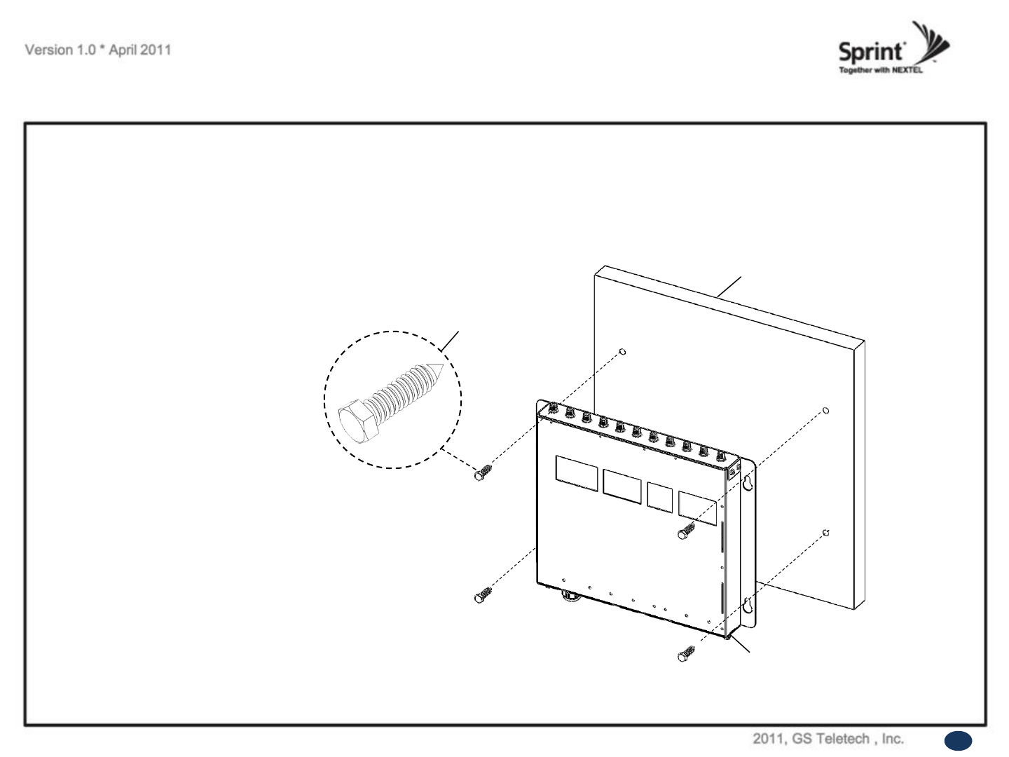
<Picture 1> Mounting the Bracket
on a Wood-Framed Wall.
Mounting Repeater
Wood-Framed Wall
• It is recommended to first attach a sheet of plywood to the wall. The sheet of plywood should be anchored to the studs in the wall.
• Using a pencil, mark the location for each of the mounting bracket's four mounting holes on the plywood.
• Place the mounting bracket over the four lag screws heads.
• Thread a lag screw at the positions marked in step 2.
Mounting Bracket
Lag Screw
1/2” x 2”
Wood-Framed Wall
6
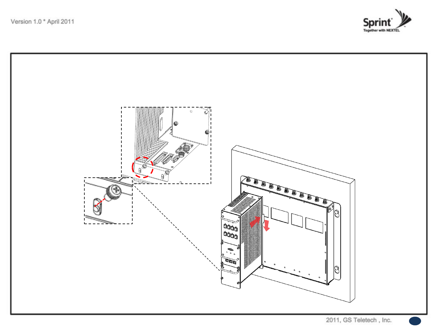
Hang and Grounding
<Picture 2> Hanging the PSU Unit.
• Hang the PSU unit to the mounting bracket.
• Locate the two Mounting Sems Screws (M6 x10mm) underneath the PSU unit. Tighten bolts until secure.
Mounting Sems Screw
M6 x 10mm
7
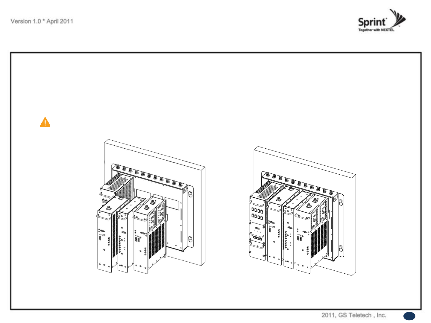
Hang and Grounding
• Hang the rest of the units in the following order: 800/900 AMP.
• Locate the two Mounting Sems Screws (M6 x10mm) underneath each unit. Tighten bolts until secure.
<Picture 3> Hanging the Rest of Units.
CAUTION
Units must be hung in the following order only: DFM -> 800/900 AMP.
8
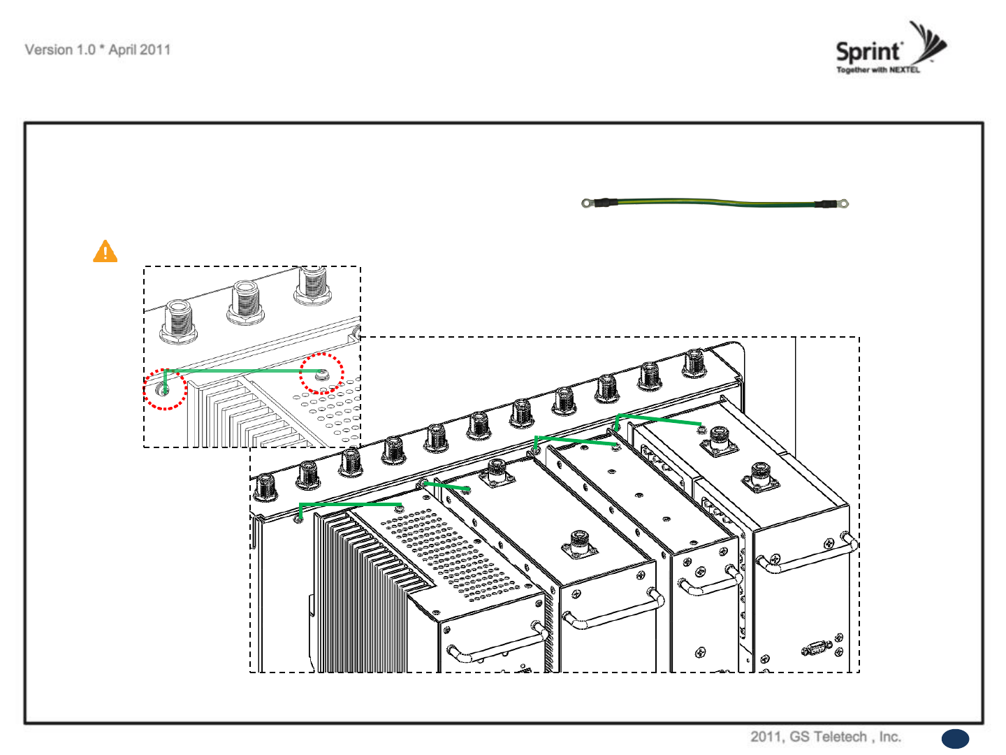
Hang and Grounding
Ground Cable
• Connect ground cables of each unit to the bracket using Ground Sems Screws (M4 x 8mm) as displayed at the picture below.
CAUTION
Ground cables must be properly grounded to provide both EMI and voltage surge protection for the repeater.
<Picture 3> Grounding of the PSU, 1900 AMP, DFM, 800/900 AMP Units.
9
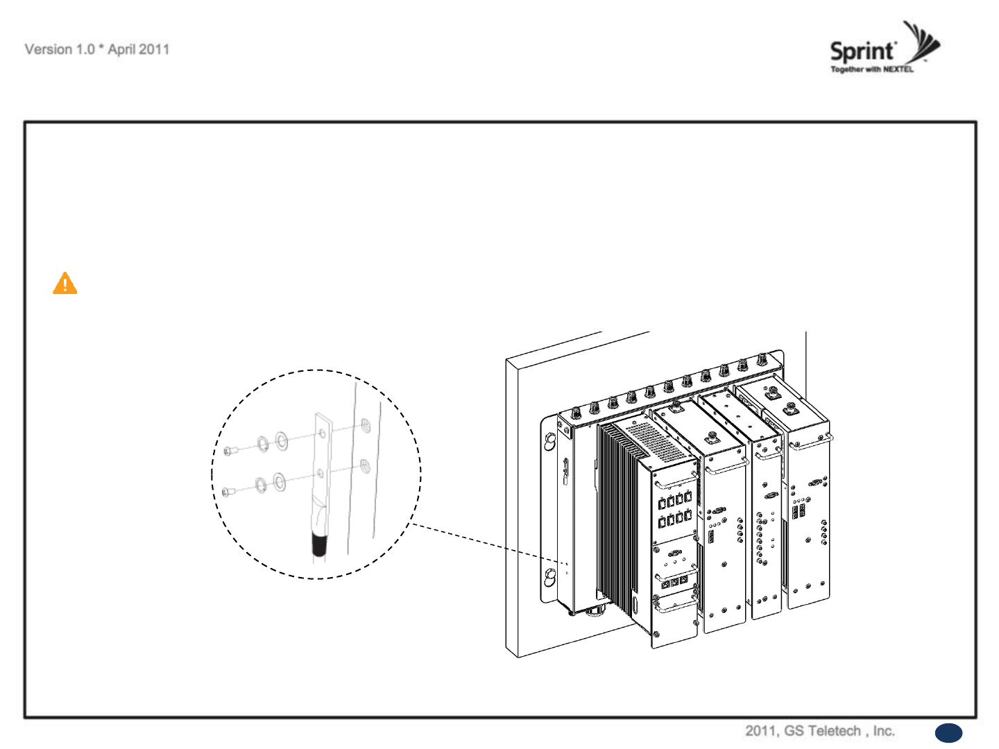
Hang and Grounding
<Picture 4> Grounding the Bracket.
• Locate the ground lug on the underside (or side) of the bracket.
• Crimp the ground cable to the ground lug.
• Route the free end of the ground cable to an approved (per local code or practice) ground source.
CAUTION
Ground cable must be properly grounded to provide both EMI and voltage surge protection for the repeater.
10

Position Antenna
• After installing 800/900MHz antennas the installer should make line of site.
• Customer specifications should be followed for positioning the antennas properly.
Warning: In order to avoid the possibility of exceeding the FCC radio frequency exposure limits,
human proximity to the antenna should not be less than 50cm during normal operation. The gain of the antenna is 12 dBi.
<Picture 5> An installer is directing Donor Antenna to
nearby BTS to receive strong input signal.
11
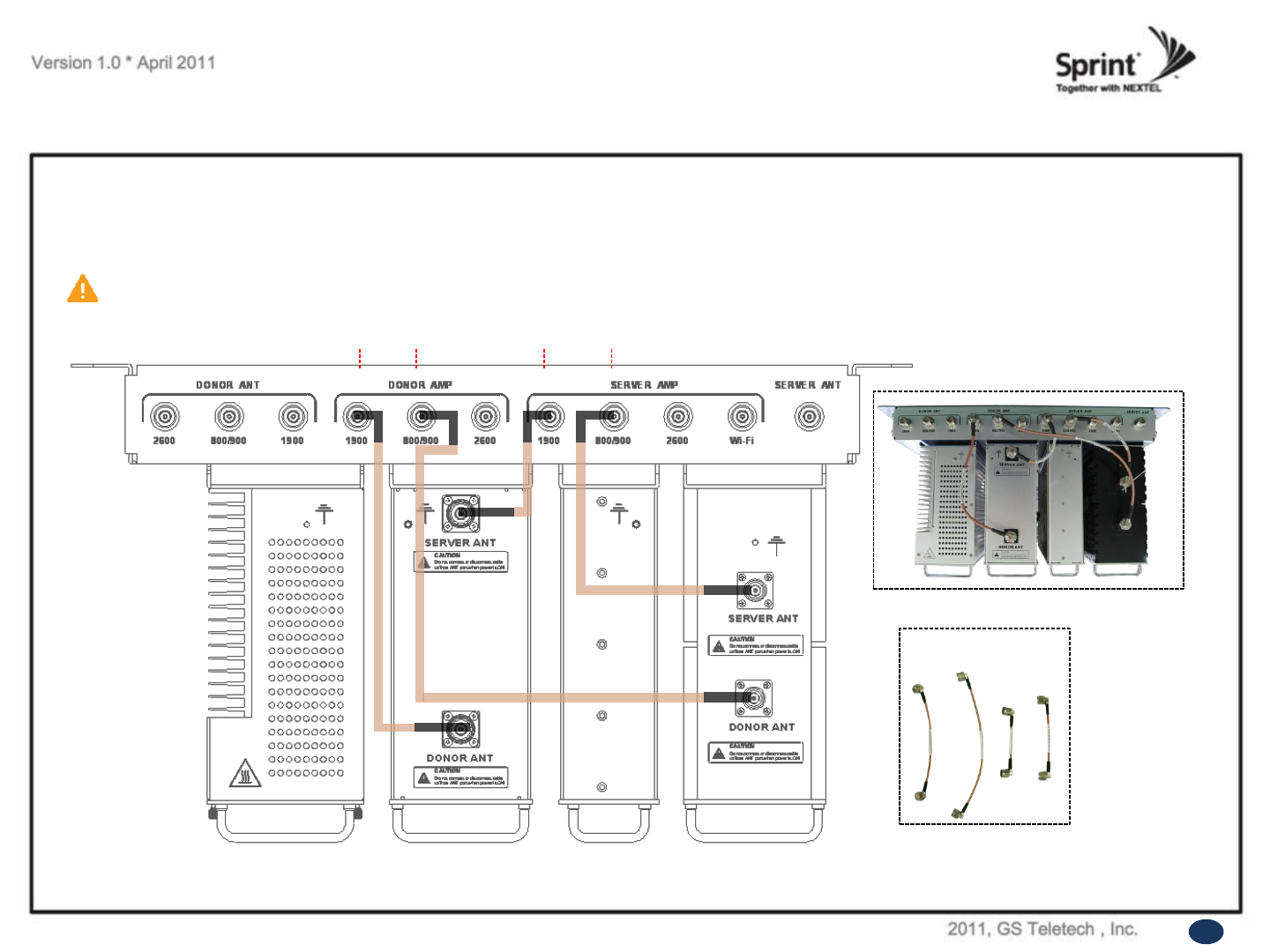
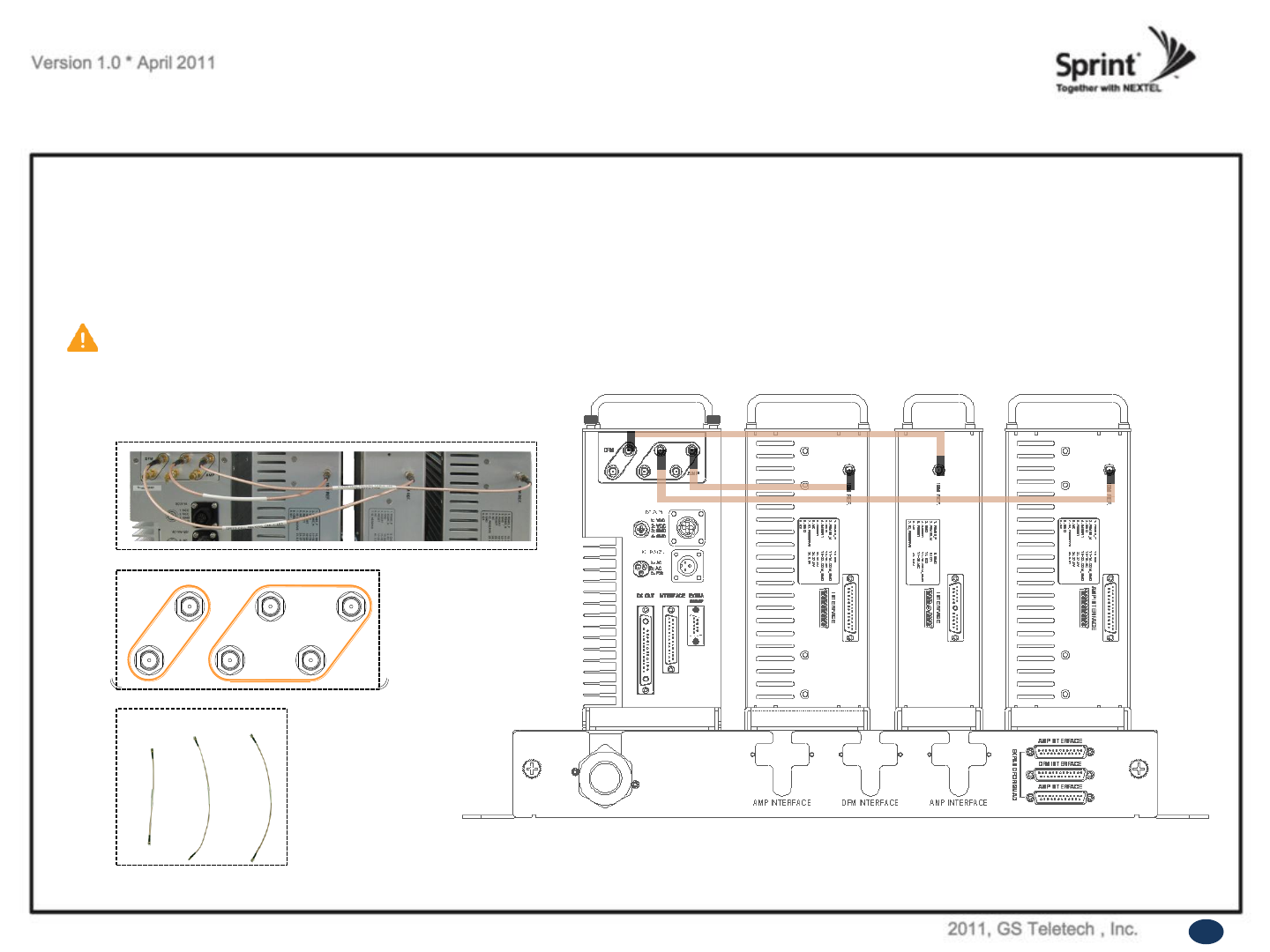
RF Cable Connections: Top of The Repeater
CAUTION
Do not connect or disconnect cable from ANT port when power is ON.
• Connect the 800/900 Antennas to their corresponding ports.
• Plug in four N(M) to N(M) type RF cables as demonstrated in the picture below.
A B C D
A B CD
<Picture 6> Top View of the Repeater.
12
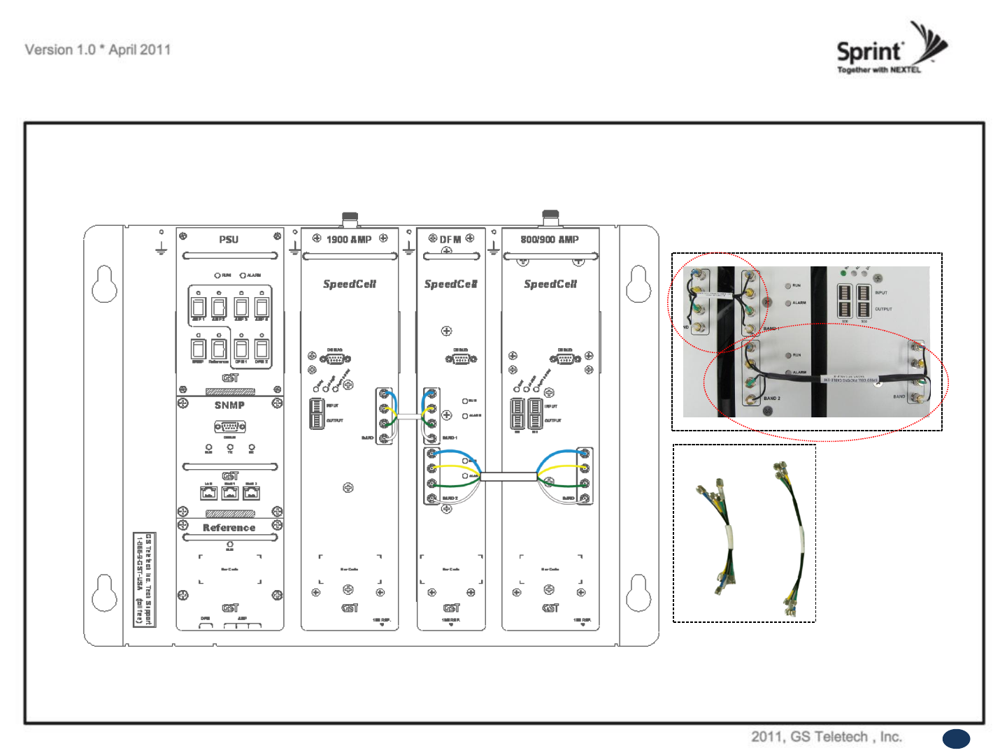
RF Cable Connections: Front Side
A
B
• Take out two SMA (M) to SMA (M) type RF cables.
• Please, pay attention to cable‟s corresponding number and its color while connecting.
• 800/900 AMP and DFM via Band 2.
<Picture 7> Front View of the Repeater.
13
A B
RF Cable Connections: Bottom of The Repeater
• Take out three SMA (M) to SMA (M) type RF cables.
• While connecting the PSU and the DFM units underneath, use referenced cable and pay attention to the labels. Plug them into
their corresponding outlets.
• User may choose either of the two SMA ports on the bottom of the PSU to connect to the DFM.
• User may choose any two of the four SMA ports on the bottom of the PSU to connect to amplifiers.
CAUTION
Please, pay attention while connecting PSU and DFM, PSU and 800/900 AMP. The repeater will not work if
connection is inappropriate.
<Picture 8> Bottom View of the Repeater.
14
10M REF.
13 12 11 10 9 7 6 5 4 3 2 1
14151617181920
8
2122232425
1. RS485_P
2. RS485_N
3. GND
4. INSERT
5. RESET
6. NC
7. ID_RESERVE
8. GND
9. ID1
10. ID2
11~14. COM_GND
15~18. NC
19~22. COM_GND
23. 27.5V
24. 27.5V
25. 6.5V
INTERFACE
10M REF.
13 12 11 10 9 7 6 5 432 1
14151617181920
8
2122232425
1. RS485_P
2. RS485_N
3. GND
4. INSERT
5. RESET
6. NC
7. ID_RESERVE
8. GND
9. ID1
10. ID2
11~14. COM_GND
15~18. NC
19~22. COM_GND
23. 27.5V
24. 27.5V
25. 6.5V
AMP INTERFACE
10M REF.
10 9 7 6 5 432 1
11121617181920
8
1. RS485_P
2. RS485_N
3. GND
4. INSERT
5. RESET
6. NC
7. ID_RESERVE
8. GND
9. ID1
10. ID2
11~16. COM_GND
17~20. NC
A1. 5.5V
INTERFACE
1415 13
A1
C A
B
1: VCC
2: VCC
3: GND
4: GND
INTERFACE EXTRA
SNMP
A: AC
B: AC
C: F.G
DC OUT
DFM
AMP
AMP INTERFACE
DFM INTERFACE
AMP INTERFACE
EXPAND FOR QUAD
AMP INTERFACE DFM INTERFACE AMP INTERFACE
1.
A B C
10M REF.
13 12 11 10 9 7 6 5 4 3 2 1
14
1516
17
181920
8
2122
23
24
25
1. RS485_P
2. RS485_N
3. GND
4. INSERT
5. RESET
6. NC
7. ID_RESERVE
8. GND
9. ID1
10. ID2
11~14. COM_GND
15~18. NC
19~22. COM_GND
23. 27.5V
24. 27.5V
25. 6.5V
INTERFACE
10M REF.
13 12 11 10 9 7 6 5 4 3 2 1
14
1516
17
181920
8
2122
23
24
25
1. RS485_P
2. RS485_N
3. GND
4. INSERT
5. RESET
6. NC
7. ID_RESERVE
8. GND
9. ID1
10. ID2
11~14. COM_GND
15~18. NC
19~22. COM_GND
23. 27.5V
24. 27.5V
25. 6.5V
AMP INTERFACE
10M REF.
10 9 7 6 54 3 2 1
11121617181920
8
1. RS485_P
2. RS485_N
3. GND
4. INSERT
5. RESET
6. NC
7. ID_RESERVE
8. GND
9. ID1
10. ID2
11~16. COM_GND
17~20. NC
A1. 5.5V
INTERFACE
1415 13
A1
C A
B
1: VCC
2: VCC
3: GND
4: GND
INTERFACE EXTRA
SNMP
A: AC
B: AC
C: F.G
DC OUT
DFM
AMP
AMP INTERFACE
DFM INTERFACE
AMP INTERFACE
EXPAND FOR QUAD
AMP INTERFACE DFM INTERFACE AMP INTERFACE
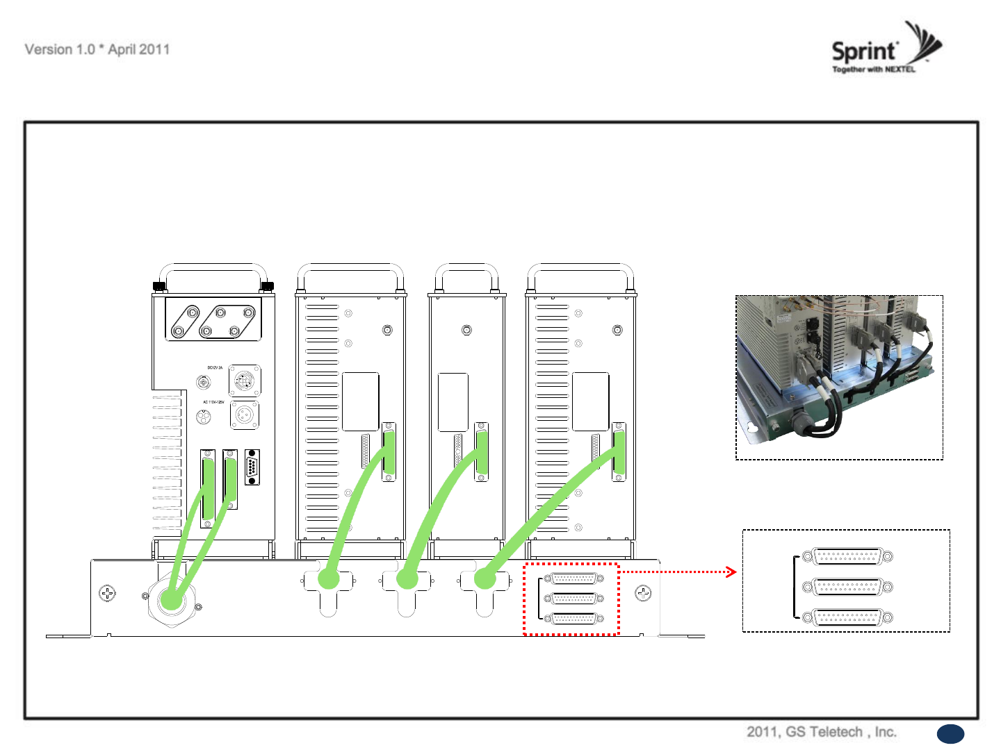
Power Cord Connections
• Plug in the cables to PSU, DFM and 800/900 AMP as displayed at the picture below.
10M REF.
13 12 11 10 9 7 6 5 4 3 2 1
14151617181920
8
2122232425
1. RS485_P
2. RS485_N
3. GND
4. INSERT
5. RESET
6. NC
7. ID_RESERVE
8. GND
9. ID1
10. ID2
11~14. COM_GND
15~18. NC
19~22. COM_GND
23. 27.5V
24. 27.5V
25. 6.5V
INTERFACE
10M REF.
13 12 11 10 9 7 6 5 432 1
14151617181920
8
2122232425
1. RS485_P
2. RS485_N
3. GND
4. INSERT
5. RESET
6. NC
7. ID_RESERVE
8. GND
9. ID1
10. ID2
11~14. COM_GND
15~18. NC
19~22. COM_GND
23. 27.5V
24. 27.5V
25. 6.5V
AMP INTERFACE
10M REF.
10 9 7 6 5 432 1
11121617181920
8
1. RS485_P
2. RS485_N
3. GND
4. INSERT
5. RESET
6. NC
7. ID_RESERVE
8. GND
9. ID1
10. ID2
11~16. COM_GND
17~20. NC
A1. 5.5V
INTERFACE
1415 13
A1
C A
B
1: VCC
2: VCC
3: GND
4: GND
INTERFACE EXTRA
SNMP
A: AC
B: AC
C: F.G
DC OUT
DFM
AMP
AMP INTERFACE
DFM INTERFACE
AMP INTERFACE
EXPAND FOR QUAD
AMP INTERFACE DFM INTERFACE AMP INTERFACE
<Picture 9> Bottom View of the Repeater.
15
These ports are used for an added
2600 MHz amplifier while extension
of the repeater.
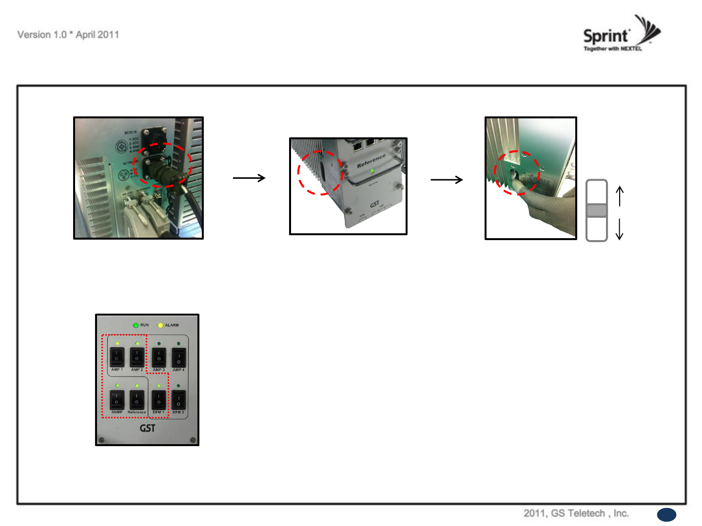
Connecting Power Cable and LED Light Verification
• Connect Power Cable
16
<Picture 10> AC Power Port Connection.
System On
System Off
<Picture 12> Verification of LED Lights.
• Turn the switch “ON” on the left side of PSU.
<Picture 11> ON/OFF Switch of SpeedCell Repeater.
• Turn the switch “ON” on the front side of PSU as displayed at the picture 12.
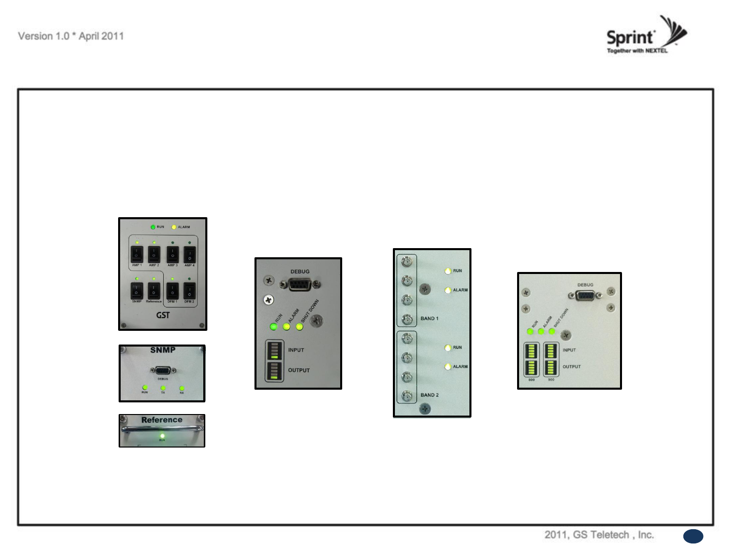
LED Indicators
• The LED‟s on the repeater will light up and should change to green as displayed at the picture below.
Tx and Rx LEDs will be blinking.
RUN LED : Green light ON.
ALARM LED : Green light is normal status, Red light is alarm status.
SHUT DOWN LED : Green light is normal status, Red light is shutdown status.
17
1900 AMP
DFM
800/900 AMP
PSU
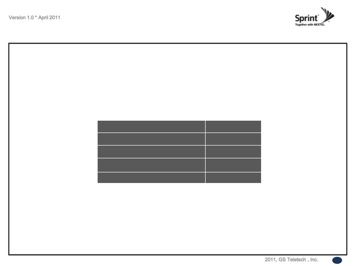
Input Power Signal
• Please note the number of LED bars for input indicates signal strength level.
The tables below indicate the levels.
Number of LED bars on the front side of Repeater will show input signal level:
Less than ~ -86dBm
LED 1bar
-85dBm~-79dBm
LED 2 bars
-78dBm~-72dBm
LED 3 bars
-71dBm~-65dBm
LED 4 bars
More than -64dBm
LED 5 bars
<Table 1> LED Bars Indication.
18

Output Power Signal
• Please note the number of LED bars for output indicates signal strength level.
Number of LED bars on the front side of Repeater will show output signal level:
Less than ~ +5dBm
LED 1bar
+6dBm~+10dBm
LED 2 bars
+11dBm~+15dBm
LED 3 bars
+16dBm~+20dBm
LED 4 bars
More than +21dBm
LED 5 bars
<Table 2> LED Bars Indication.
19
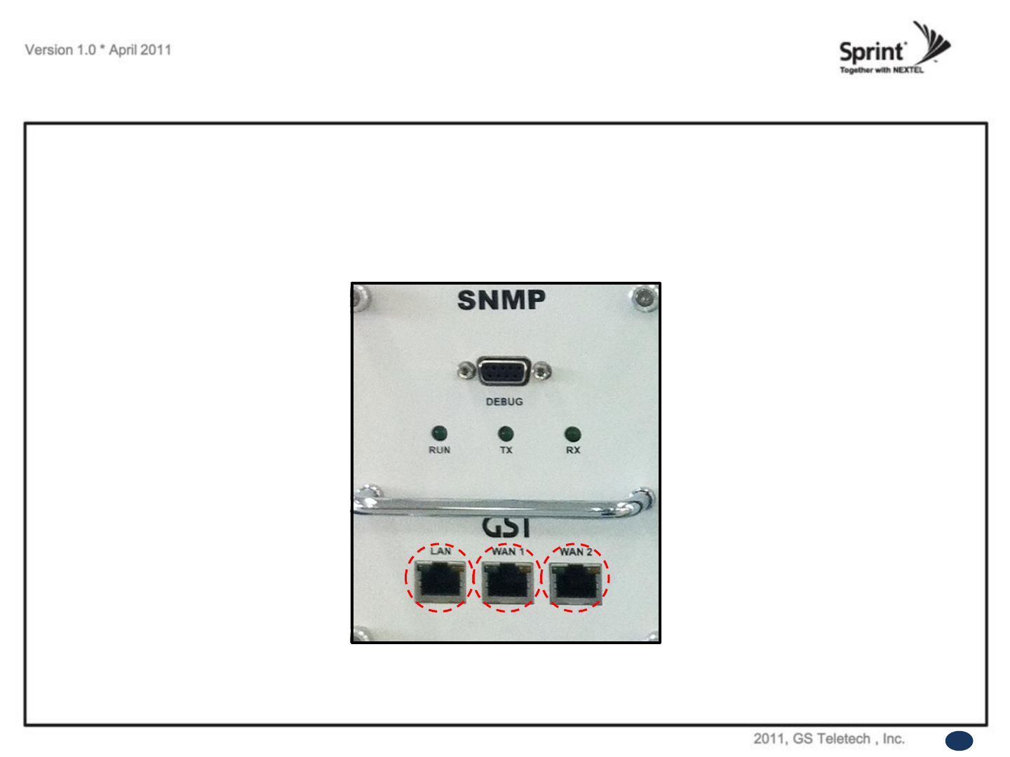
Web UI
• LAN port is used for connection of laptop and repeater.
• WAN 1 port is used for connection of repeater and wireless modem for remote access.
• WAN 2 port is a redundancy port for remote access.
<Picture 12> Ethernet Port.
1 2 3
20
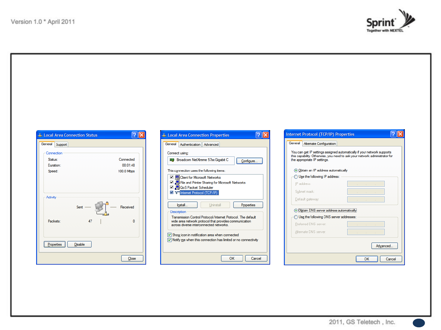
Configuring Laptop to Connect to Repeater
1. Go to Local area connection. 2. Click ‘TCP/IP Properties’. 3. Choose ‘Obtain DNS server address
automatically’.
21
• Connect Ethernet crossover cable from the LAN port of the repeater to laptop.
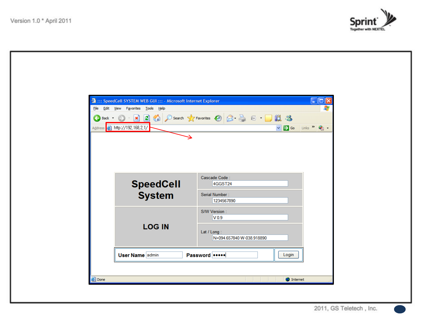
Enter IP address by 192.168.2.1, you will be redirected to Login. Default User Name is „admin‟,and default Password
is „admin‟. You may need to change password as described in the User Management section. Engineering Number
and Site Name will initially be blank, you can input Engineering Number and Site Name as described in the
Communications Configuration section.
Login Screen
22
Repeater’s IP Address: 192.168.2.1
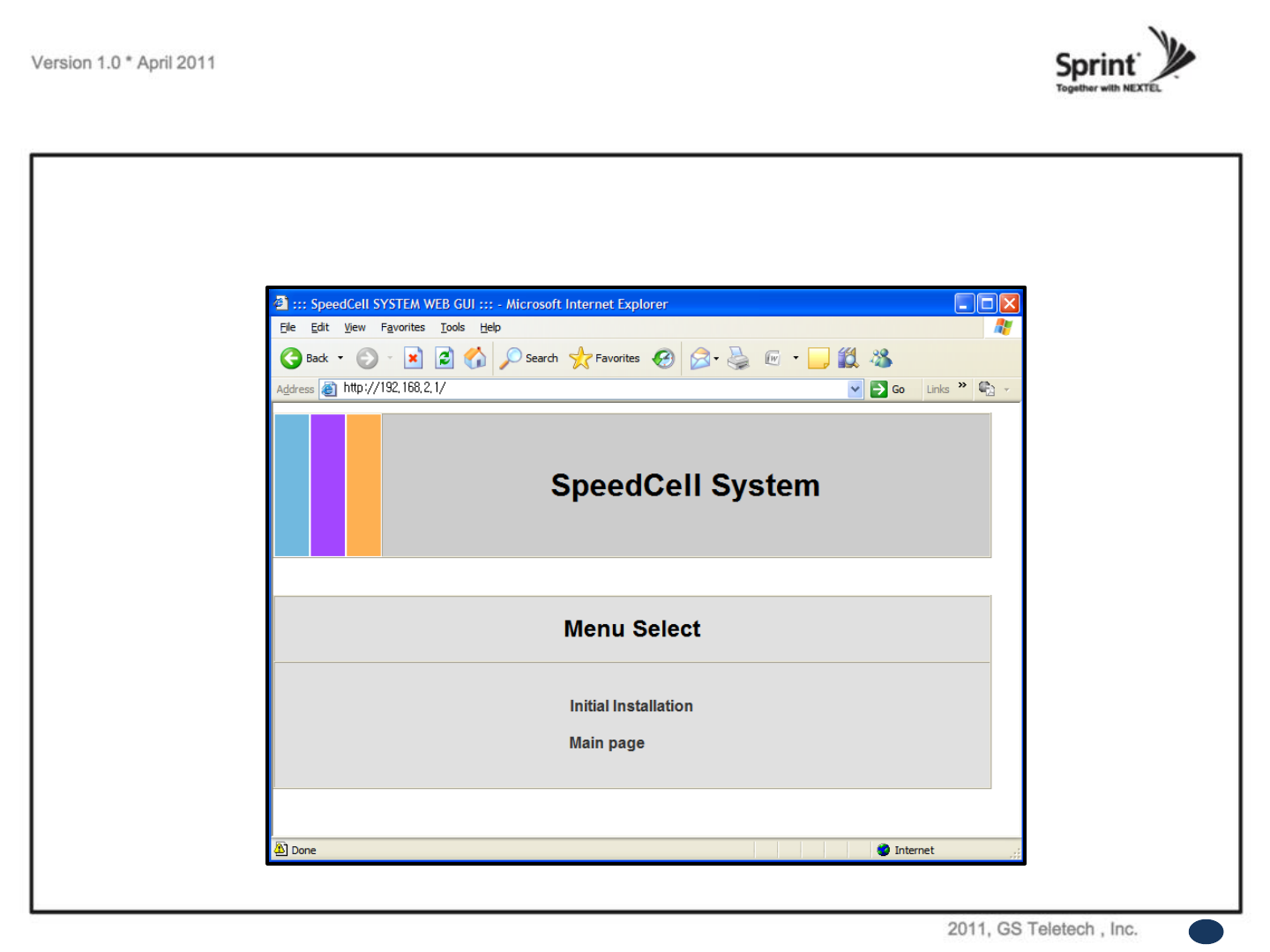
Menu Select
• After you log in, you can see „Menu Select‟ page.
• To setup the Repeater, click „Initial Installation‟.
• To go to menu list, click „Menu Page‟.
23
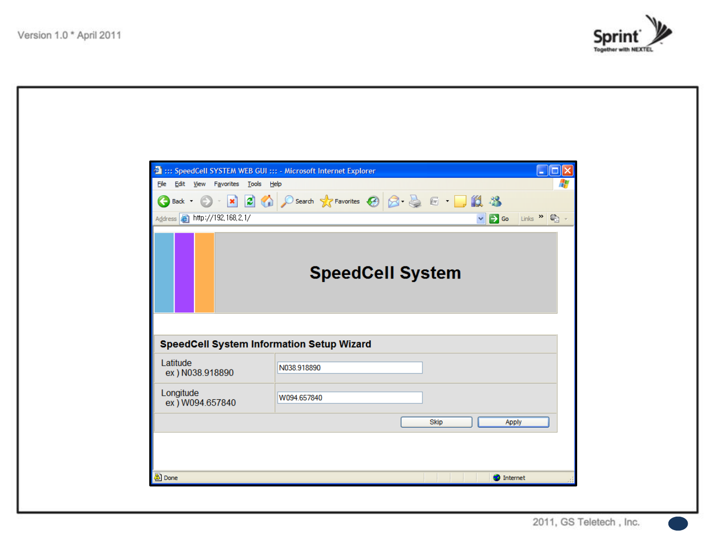
Setup Wizard
• After you clicking on „Initial Installation‟ the following screen will be displayed.
• After typing the Latitude or Longitude numbers, press „Apply‟ button.
• User may skip this window if it is unnecessary.
24
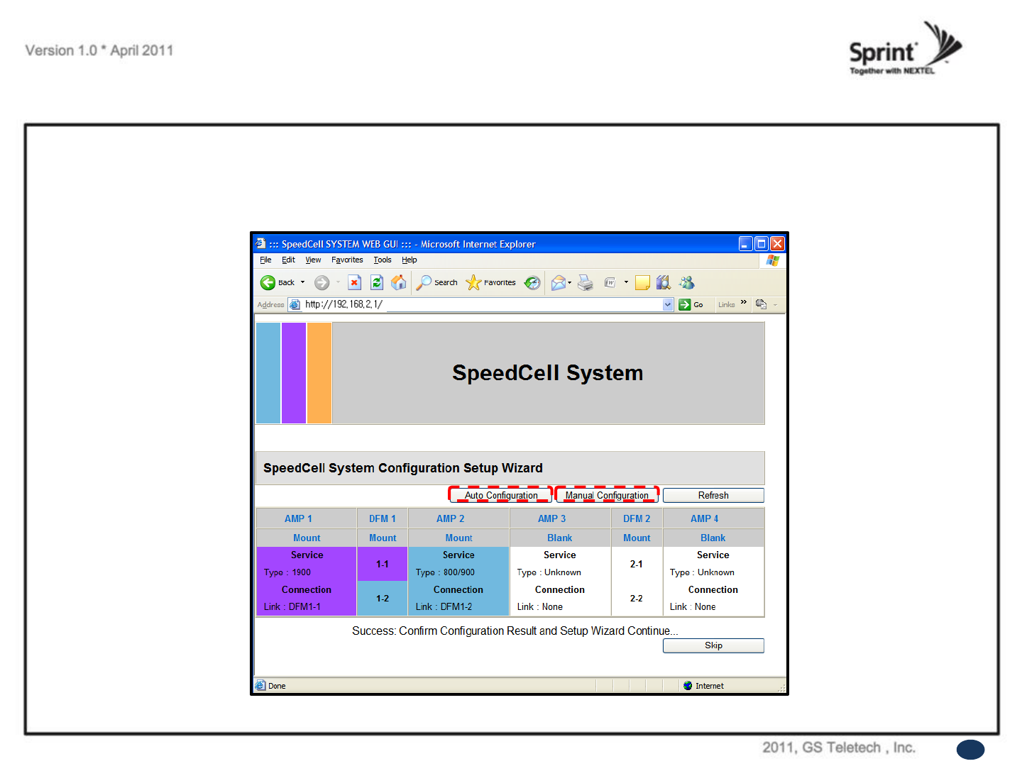
Setup Wizard
12
Auto Configuration matches amplifier and DFM units automatically.
Manual Configuration matches amplifier and DFM units manually.
① ②
①
②
25
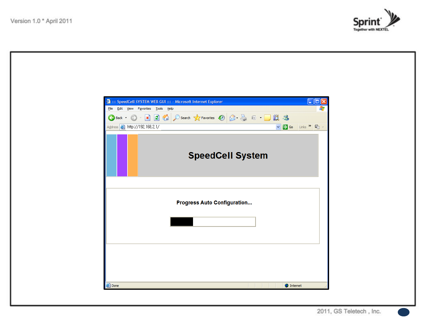
Setup Wizard
• After clicking Auto Configuration, the screen below will be displayed.
• It will take approximately one minute to finish the process.
26
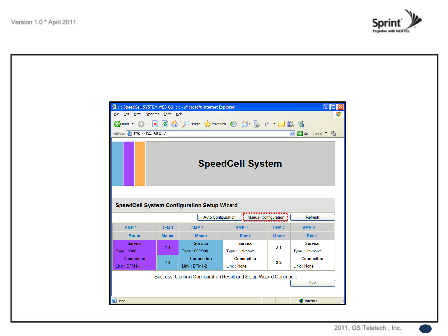
Setup Wizard
• User may also setup repeater manually by clicking on „Manual Configuration‟ button.
27
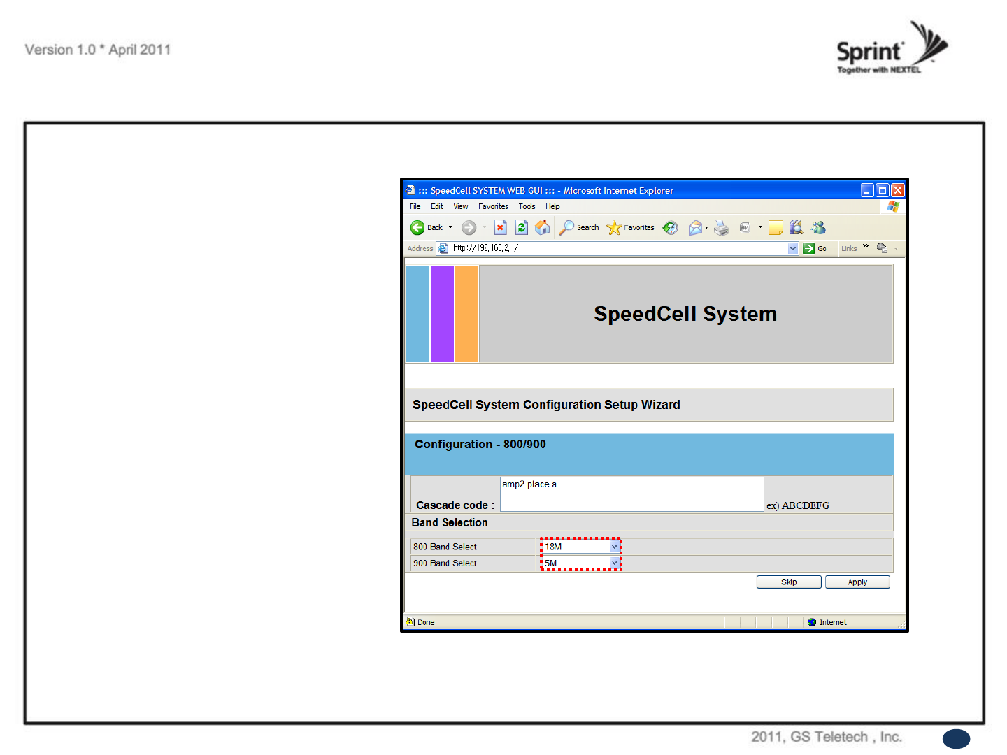
Setup Wizard
Manual Setup Wizard for 800/900MHz
Band
• User may choose bandwidth in this menu.
After selecting bandwidth, click „Apply‟ button.
• Also User may skip this setting if it is not
needed.
31

Setup Wizard
Manual Setup Wizard for 800/900MHz
Band (Choosing antenna)
• After selecting an antenna type, click „Apply‟
button.
• Also User may skip this setting if it is not
needed.
Antenna Only (AGS Setting): Repeater
sets up automatically (Auto Gain Setting,
AGS)
DAS (ALC D/L limit 7dBm Setting):
Repeater operates with Active DAS
DAS (ALC D/L limit Maximum Setting):
Repeater operates with Passive DAS
Not Use (HPA OFF): It disables this AMP
unit
32
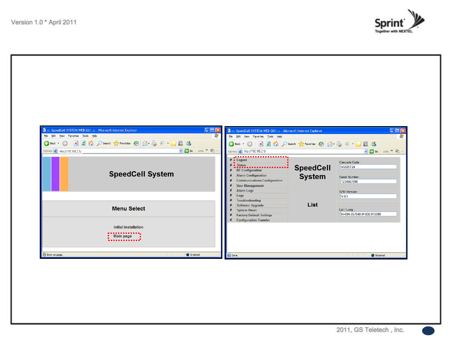
List Menu
• After clicking on „Main Page‟, the „List Menu‟ will be displayed.
• User may check the Repeater status by clicking on „Status‟.
33
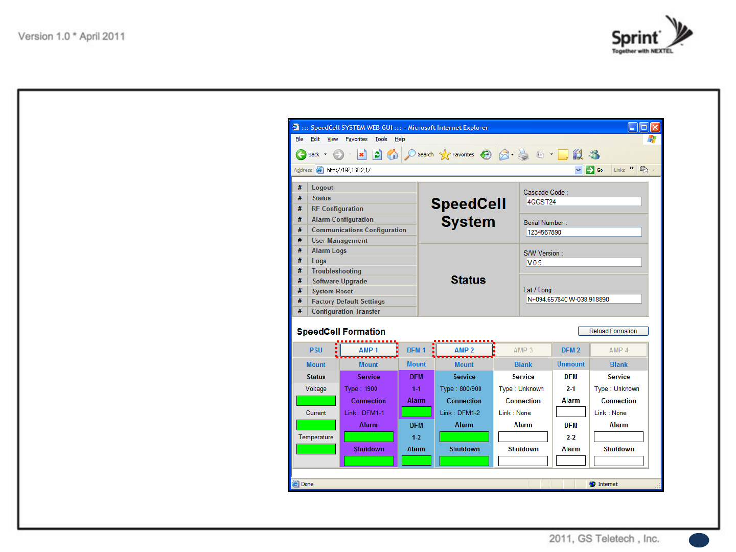
Status Menu
• User may check status of amplifiers by
clicking on any of them.
34
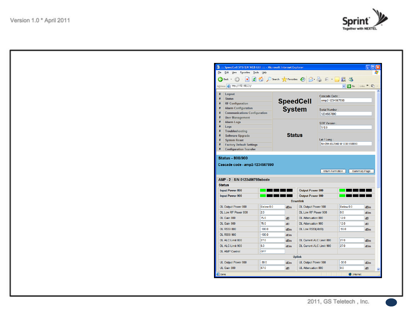
Status of 800/900 AMP
• Default D/L and U/L are set at minimum gain.
• Values will vary depending on specific site circumstances.
• In case that screen resolution is 1024 x 768, you may need
to use scroll bar to view all.
Status Menu
38
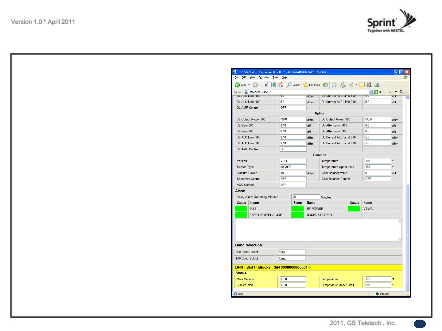
Status of 800/900 AMP
(continue of the page)
• Values will vary depending on specific site circumstances.
• In case that screen resolution is 1024 x 768, you may need
to use scroll bar to view all.
Status Menu
39
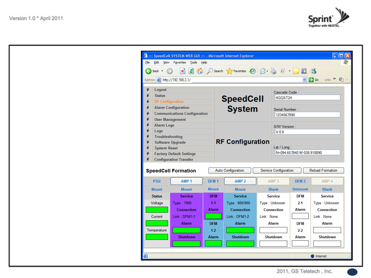
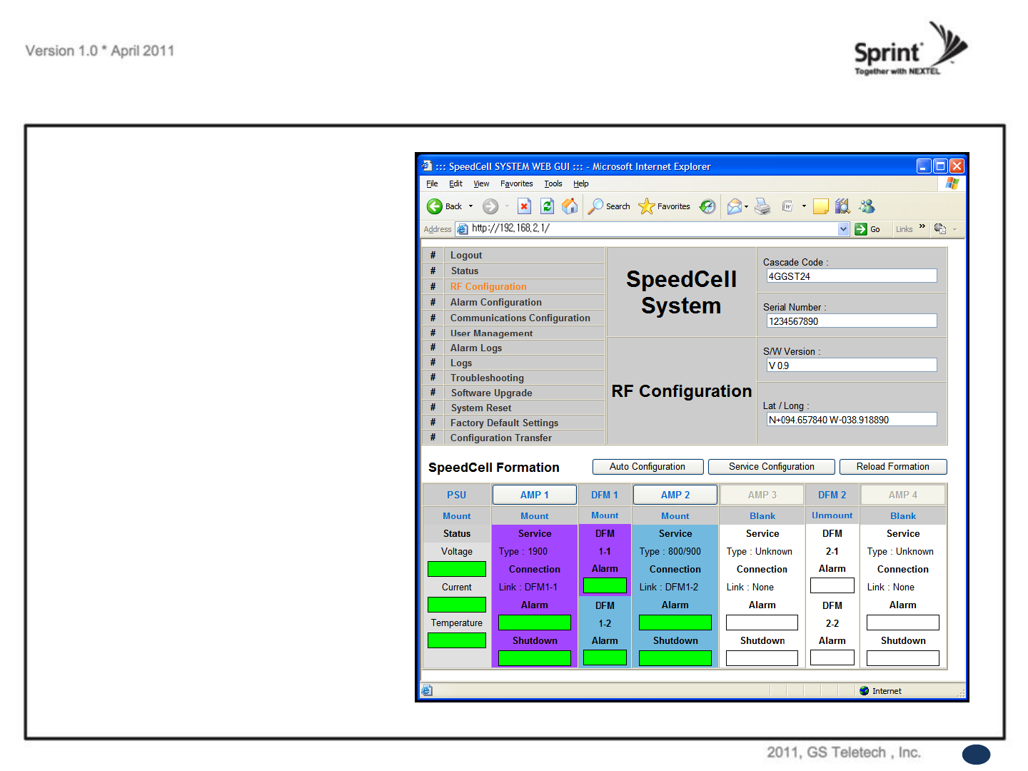
RF Configuration Menu
• Click the RF Configuration link.
• Click AMP 1 or AMP 2 in order to go to the
next window and change RF values.
40
• What is Auto Limit Control (ALC)?
ALC is used for custom installations.
If the repeater is having difficulties with isolation check, or if you want to “power down” the repeater ALC should be
manually set. Attenuation may also be added for reducing power levels. ALC also provides optional U/L and D/L
settings.
- ALC controls the output power.
- If you want to use the ALC function, Gain Balance Control should be turned off.
- ALC will reduce max gain by the set value even if the input signal decreases.
- ALC should be used if the repeater is connected to a DAS system.
• What does the Shutdown ON/OFF control?
- An internal wave-detection is checking the noise level. If the repeater cannot secure isolation it will go through a
process of turning itself off, and turning back on while doing isolation checking.
- If it is impossible for the repeater to secure isolation after 30 minutes, the repeater will shut down and stay shutdown.
The items that may automatically require the repeater to shut down are:
-> VSWR Alarm, Over Power Alarm, Over Input Alarm, and Temperature Alarm.
• What is Gain Balance Control?
- Gain Balance Control will always keep the UL and DL ATT the same while using AGC.
GBC should always be left on to prevent damage to BTS while using AGC.
- This is used for BTS to cell phone power control.
RF Configuration Menu FAQ’s
41
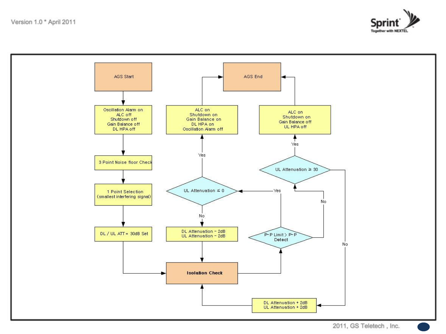
Auto Gain Setting (AGS) Flow Chart
42
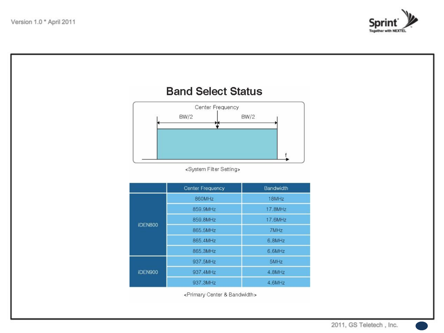
800/900MHz Band Selection
RF Configuration Menu
44
• Click the RF Configuration link.
Click AMP 1or AMP 2 in order to go to the
next window and change RF values.
RF Configuration Menu
45
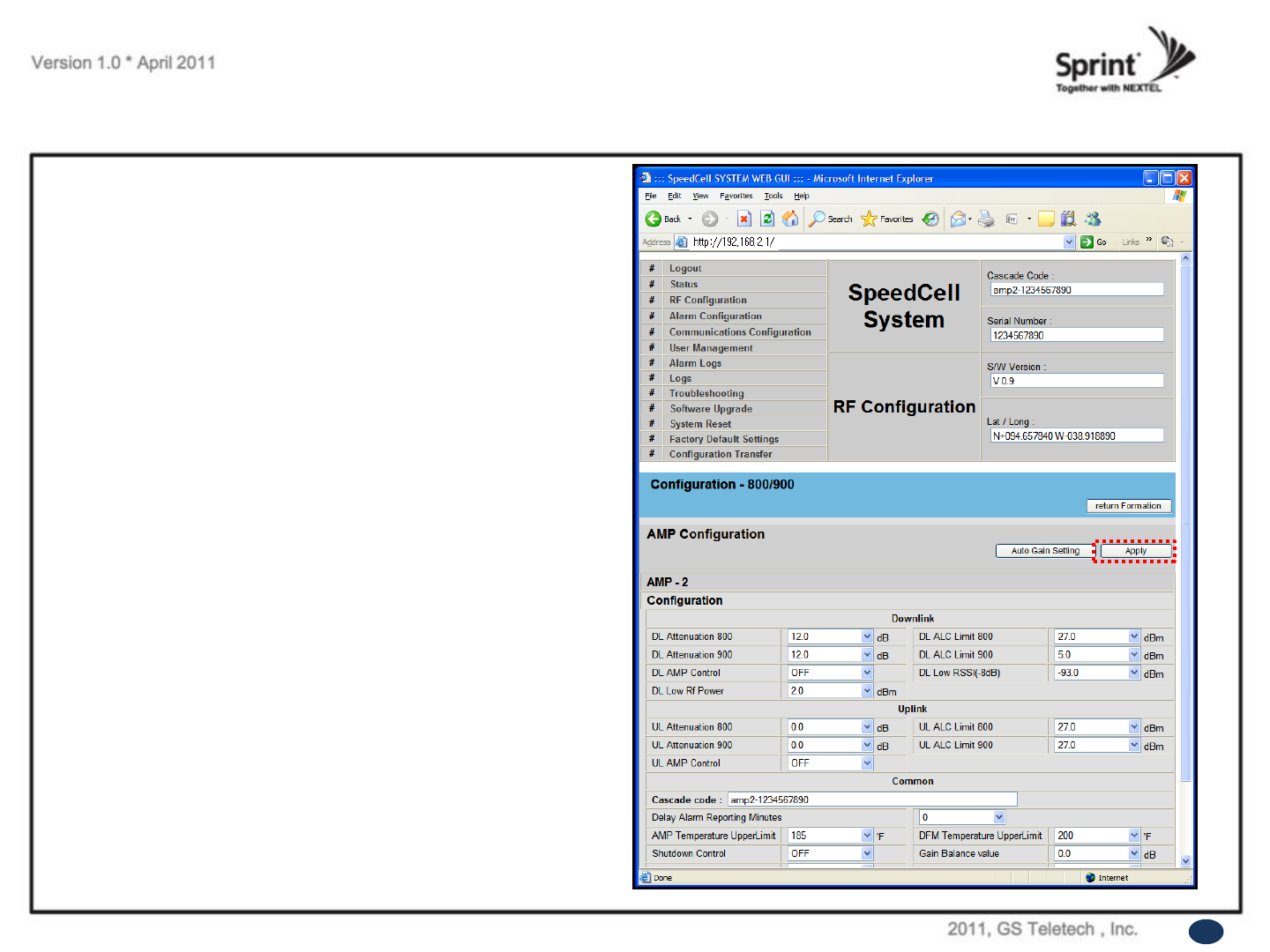
RF Configuration Menu
800/900 AMP
• User may change various RF values of the repeater
on this page.
•Changes will not take effect until you click “Apply”
button.
• This menu is where the installer will choose
references for specific implementation.
•In case that screen resolution is 1024 x768, you may
need to use scroll bar to view all.
48
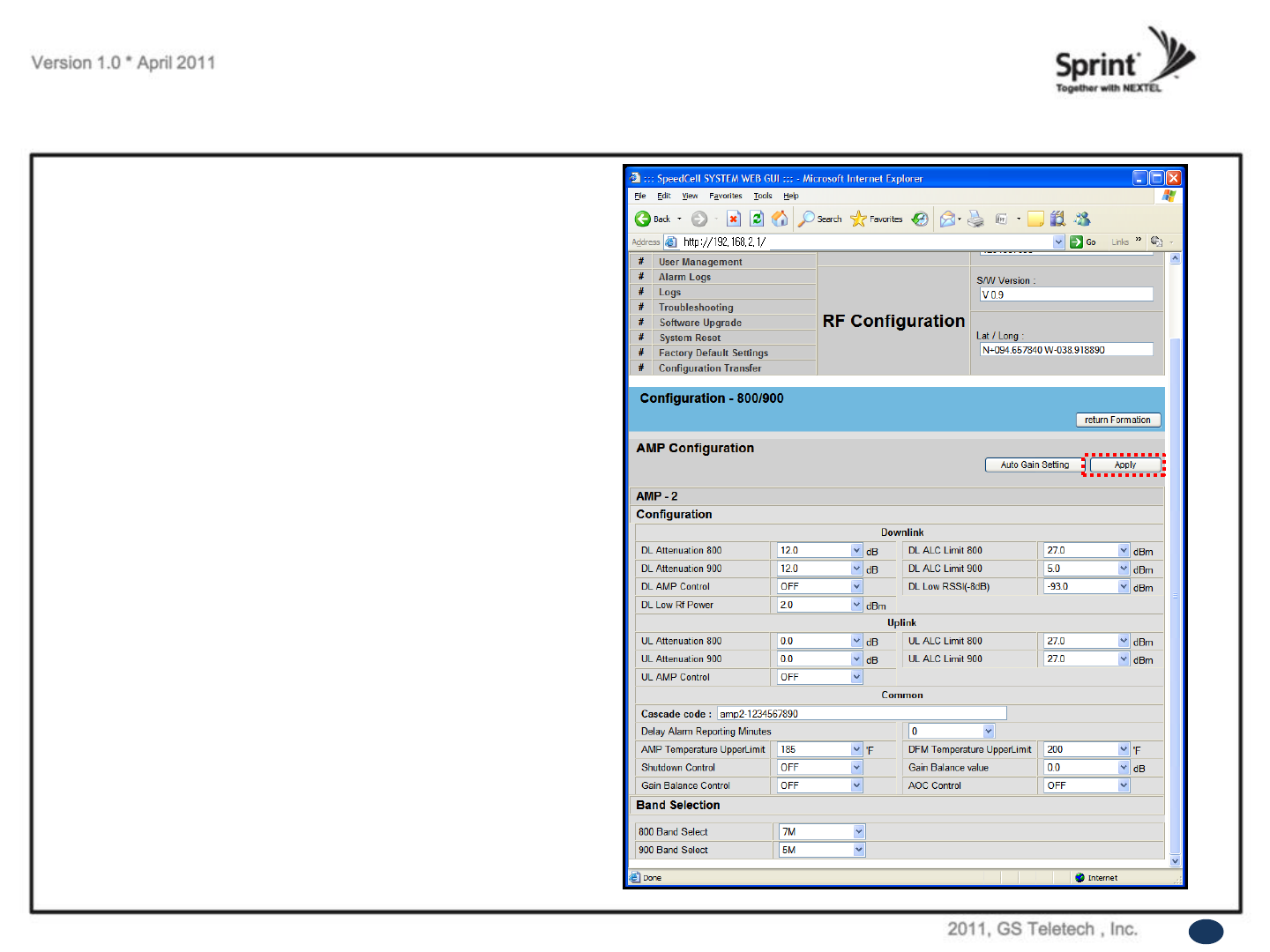
RF Configuration Menu
800/900 AMP
(continue of the page)
• User may change various RF values of the repeater
on this page.
•Changes will not take effect until you click “Apply”
button.
• This menu is where the installer will choose
references for specific implementation.
•In case that screen resolution is 1024 x768, you may
need to use scroll bar to view all.
49
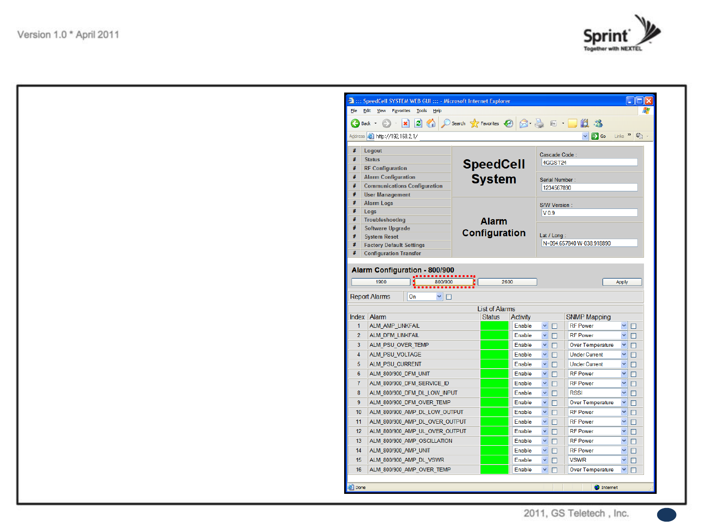
Alarm Configuration Menu
• Click „800/900‟ link to check alarm configuration of
1900AMP.
• In case that Report Alarms is OFF, all alarms will be
disabled. In case that Report Alarm is ON, you can
enable and disable individual alarms.
51
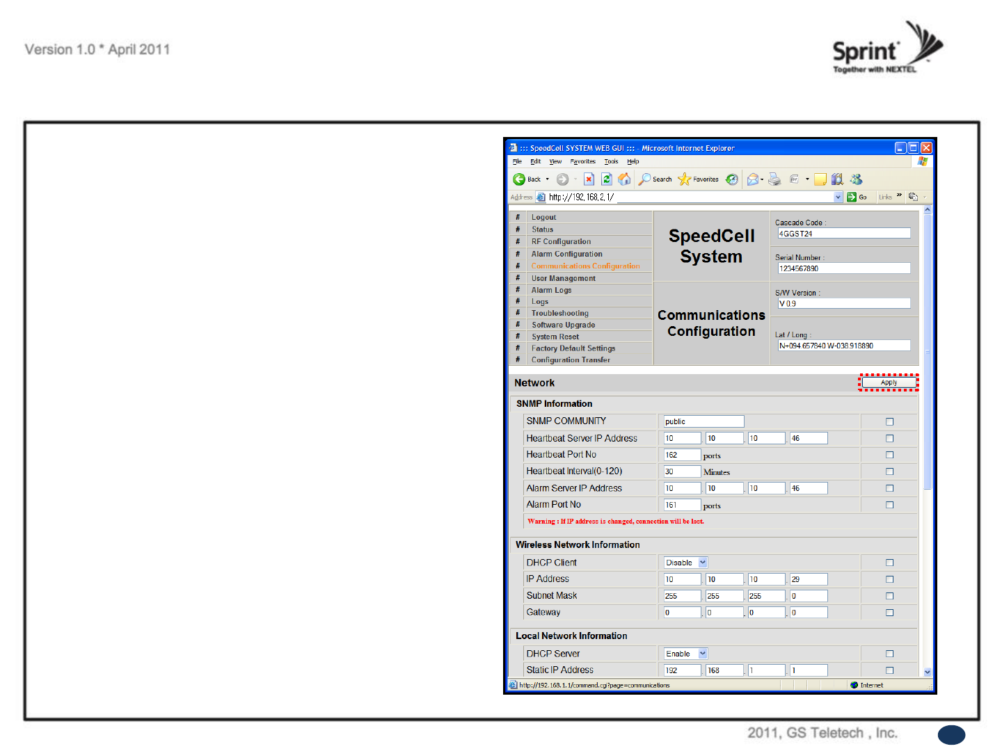
Communication Configuration Menu
• Click on the „Communications Configuration‟link.
•On this page you can change various values related to IP
network. Because Web UI is based on IP network, incorrect
configuration may make it impossible to connect to Web UI.
In that case, you can troubleshoot as described in the
Command Line Interface (CLI) section.
•In case that screen resolution is 1024 x 768, you may need
to use scroll bar to view all.
52
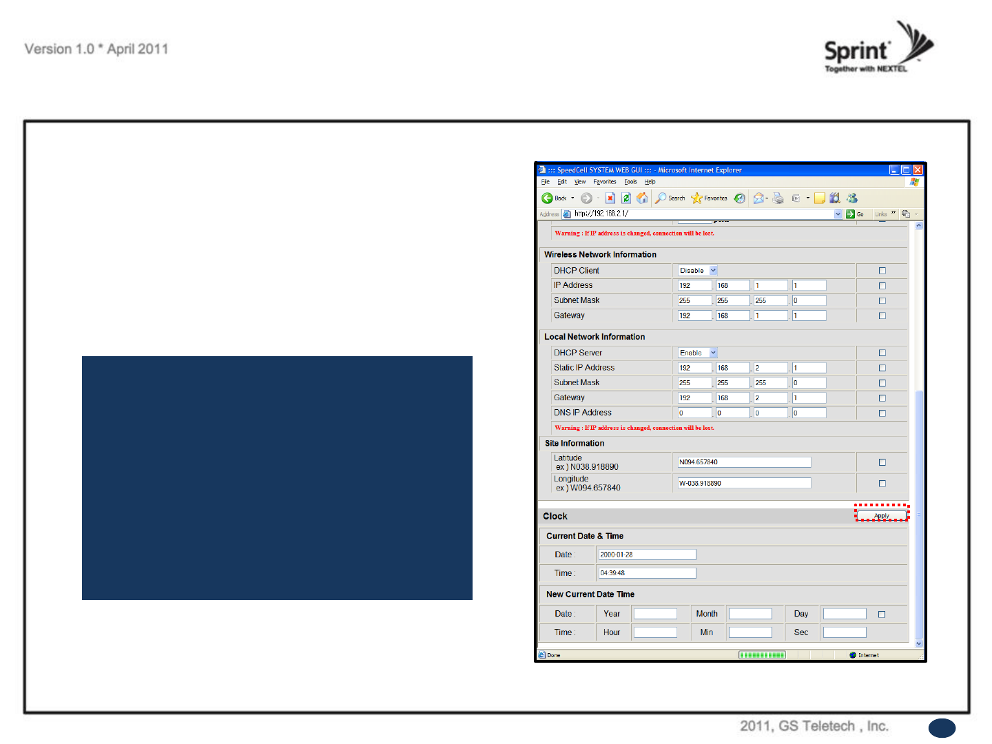
Communication Configuration Menu
•On this page you can change various values related to IP
network.
•Changes will not take effect until you click “Apply” button.
•In case that screen resolution is 1024 x768, you may need to
use scroll bar to view all.
In the line <Obtain IP address automatically> “Static” means
connection using a fixed IP.
“DHCP” means connection using DHCP, where
If "DHCP Client" is "ON", then the repeater will run as a
DHCP client.
If "DHCP Client" is “OFF", then the repeater will get a
Static IP.
“DHCP” means connection using DHCP, where
If "DHCP Server" is "ON", then the repeater will run as a
DHCP server.
53
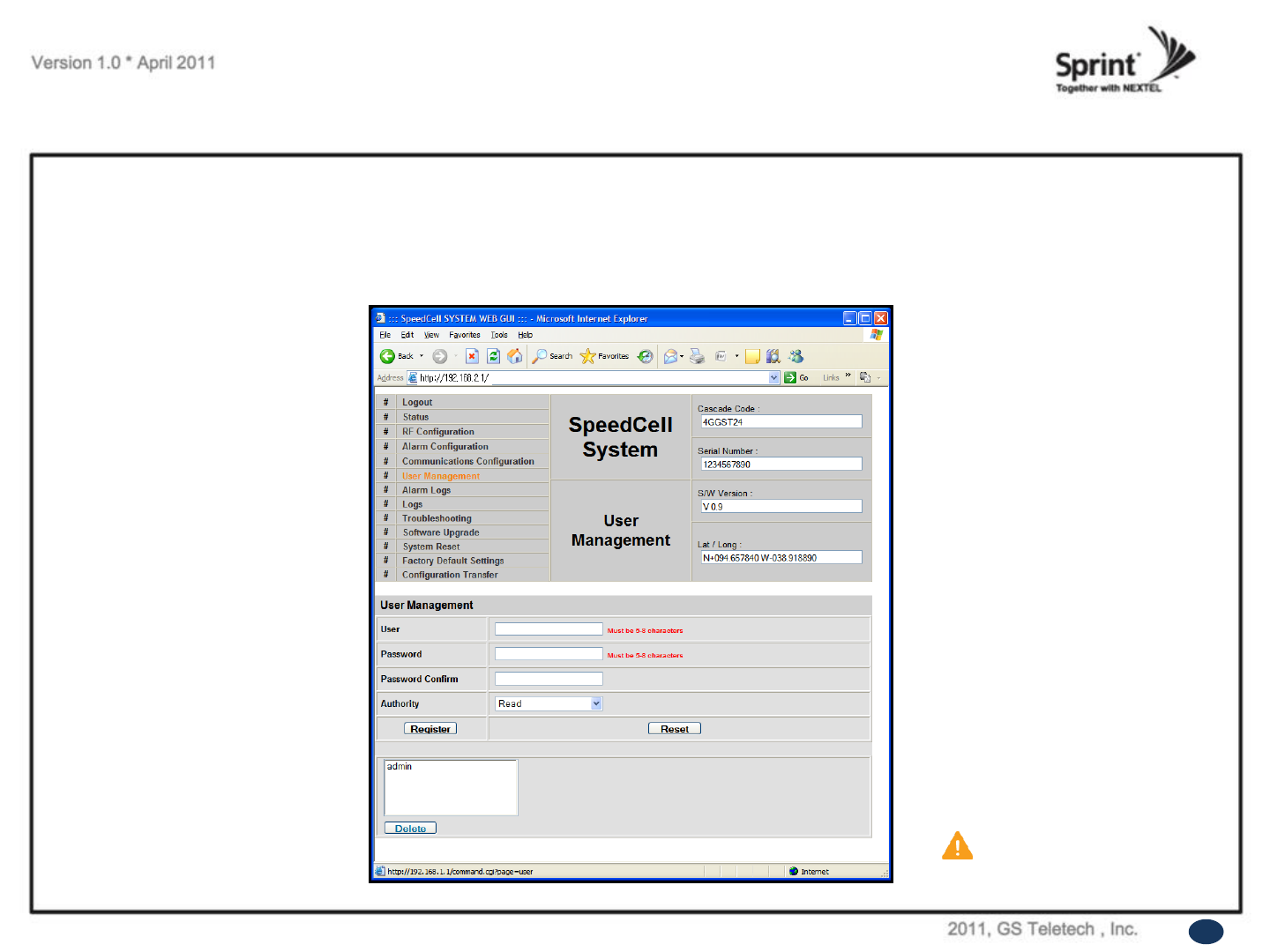
User Management Menu
CAUTION
DO NOT DELETE ‘admin’.
• Click on the „User Management‟ link.
• On this page you can create and delete users, change passwords, and assign authorities to individual users.
• Read will only all the user to view information on the menu pages, but cannot make any changes.
• Read/Write Authority means that the user can view and change various values.
• Super User is very similar to an Administrator account...
54
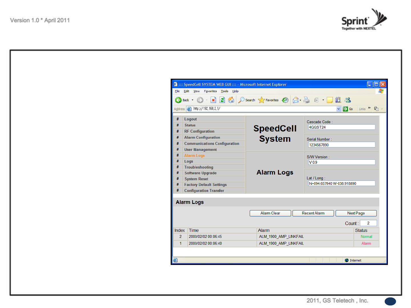
Alarm Logs
• Click on the Alarm Logs link.
• You can see a history of reported and reset
Alarms.
When an alarm is reported, the name and time
of the alarm is displayed along with it‟s current
status.
Red color means that the alarm is reported, and
green color means that the alarm has returned
to normal status.
• After an Alarm condition lasts for the “Delay
Alarm Reporting Minutes” set in RF
Configuration page, the Alarm will be reported.
55
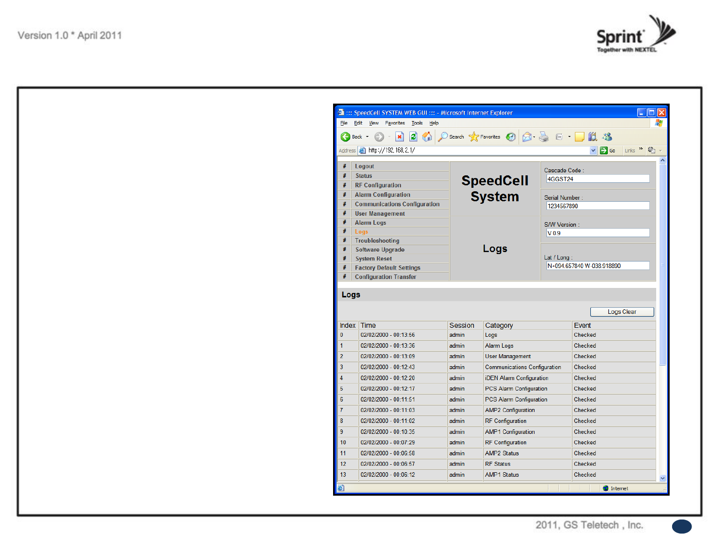
Logs
• Click on the Logs link.
• You can see Logs regarding Web UI operation.
Logs will maintain a history of up to 30 operations.
• In case that screen resolution is 1024 x 768, you
may need to use scroll bar to view all.
56
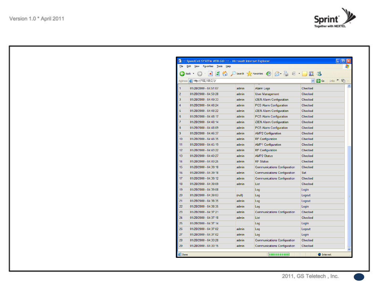
Logs
Continue of Logs page.
• In case that screen resolution is 1024 x 768, you
may need to use scroll bar to view all.
57
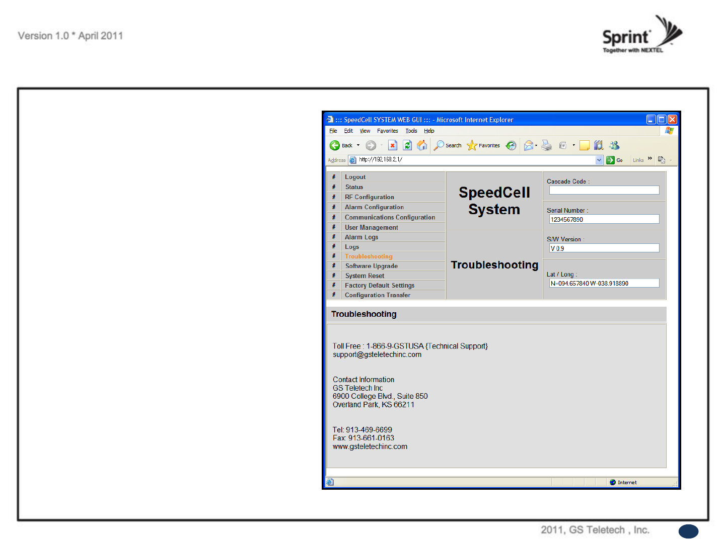
Troubleshooting
• Click on the Troubleshooting link.
• You can refer to this page for GST's technical
support.
58
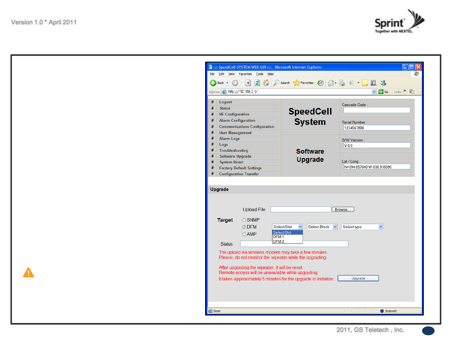
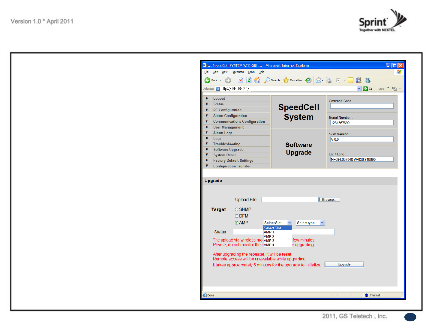
Software Upgrade
• Click on the Remote Software Upgrade link.
•In case that software upgrade is needed, you
should use this page.
• Click Browse button to select the file to
upgrade from the laptop.
• Choose the file to upgrade provided by GST.
After you choose the file, you should click
“upload” to send the file from your laptop to the
Repeater.
• Provided files are three, need to download
each of them.
- The files are,
-①SC_SNMP.MCU
-②SC_AMP.AMP
-③SC_DFM.SDR
SC_DFM.SDS
CAUTION
Be careful not to unplug the crossover
Ethernet cable during software upgrade.
59
Software Upgrade
• After uploading is finished, verify that the File
Name and the File Size is correct, then click
„Upgrade System‟button.
The lights on the repeater will be blinking and
change color during upgrade which will take about
two minutes for the upgrade to initialize.
The lights will go back to normal when upgrade is
done.
60
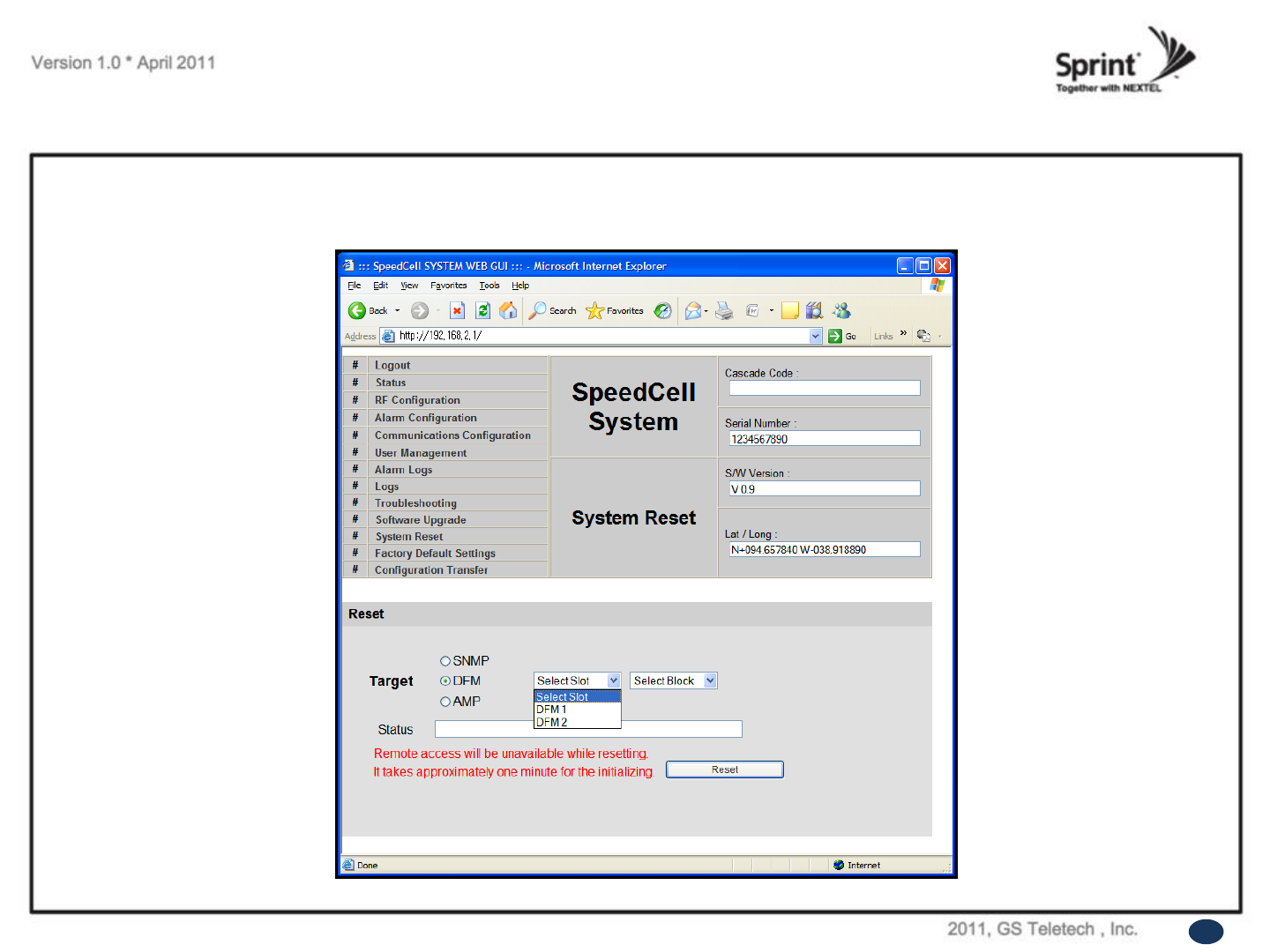
System Reset
• Click 'No' to return to the 'List' menu.
• Click 'Yes' to reset the repeater via a soft-boot. This will not change any of the current settings
61
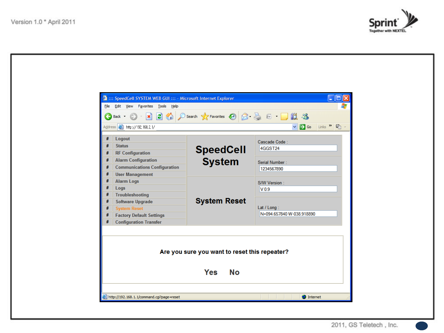
• Click 'No' to return to the 'List' menu.
• Click 'Yes' to reset the repeater via a soft-boot. This will not change any of the current settings.
System Reset
62
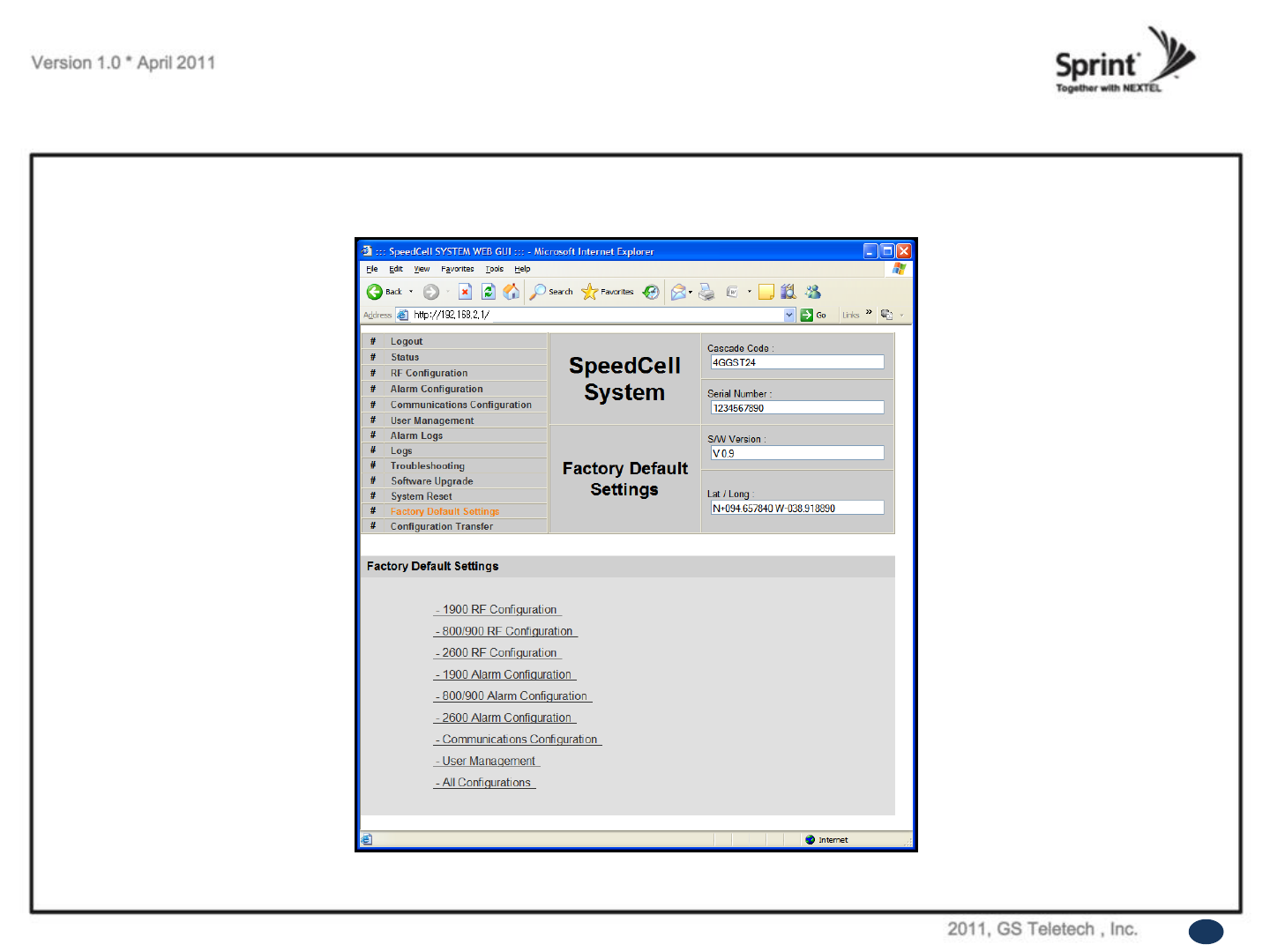
Factory Default Settings
• Choose type of configuration to be restored to factory default settings.
63
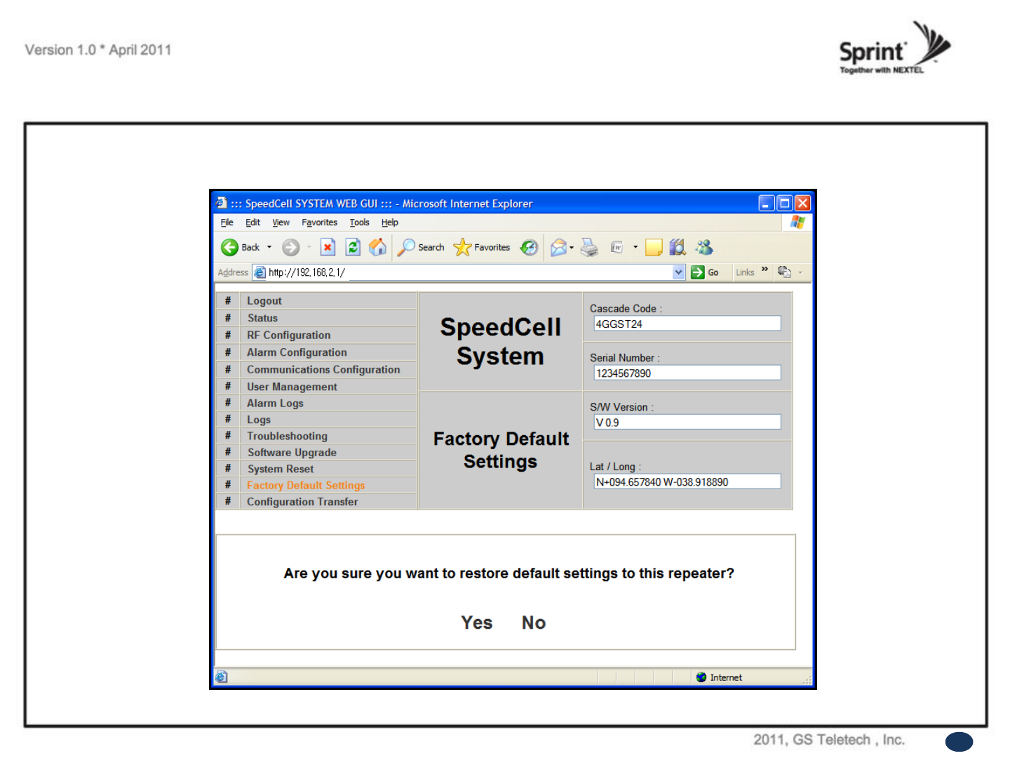
Factory Default Settings
• This function will allow you to roll back to factory default settings.
64
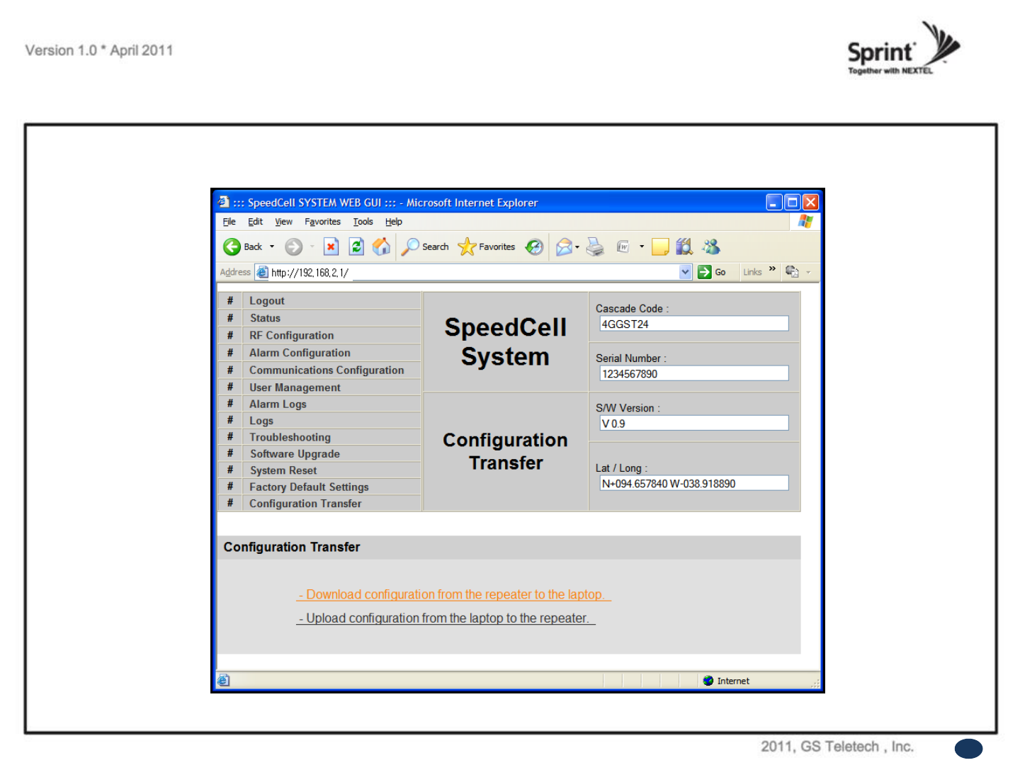
Configuration Transfer
• Configuration Transfer function is for downloading and uploading set values of the repeater.
65
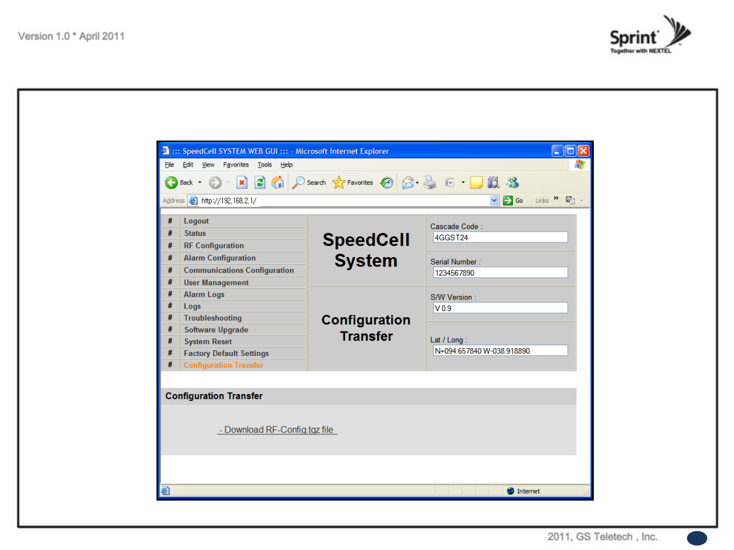
Configuration Transfer: Download
• Configuration Transfer Download Display.
66
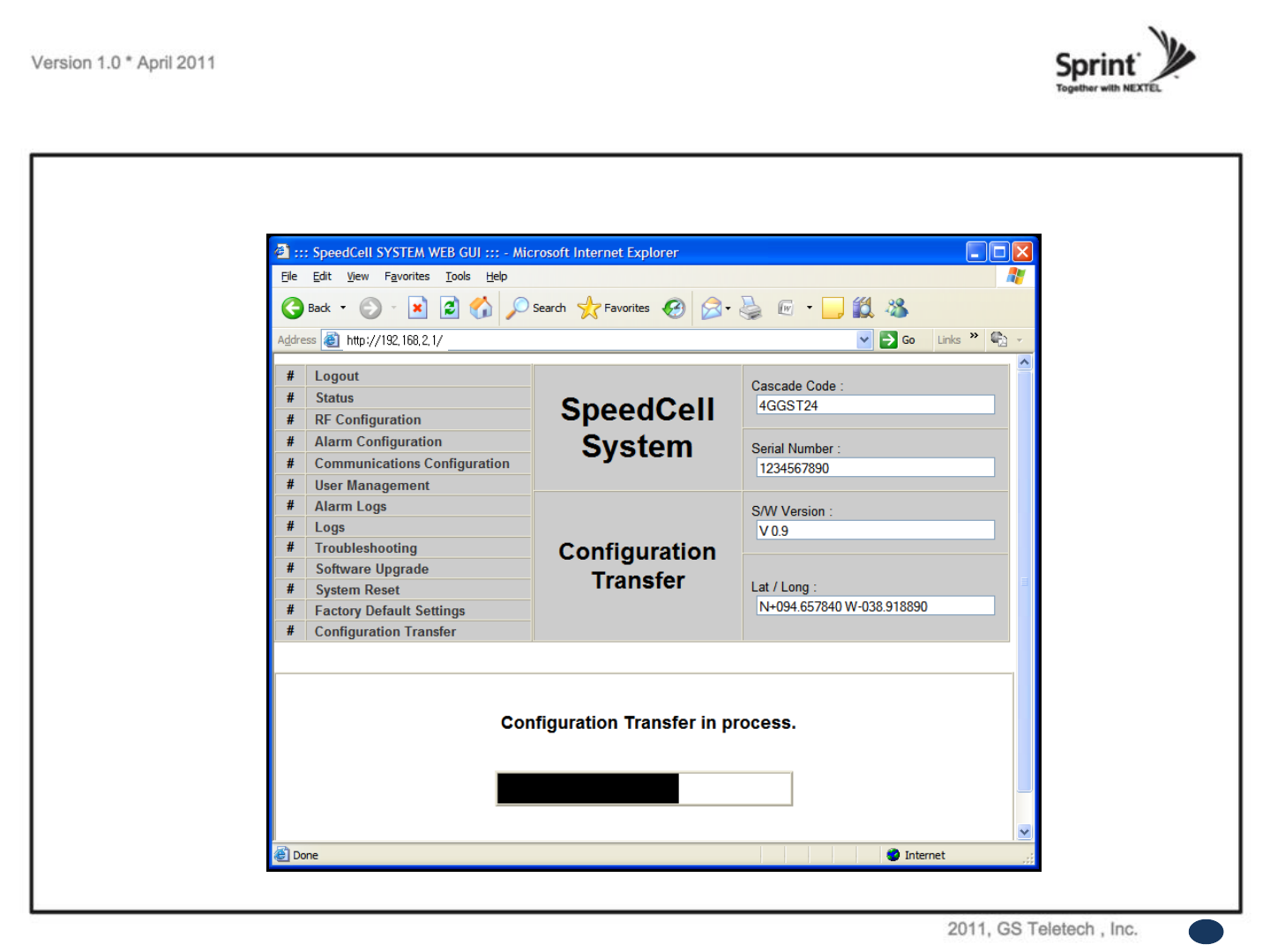
Configuration Transfer
• Downloading process of set values.
67
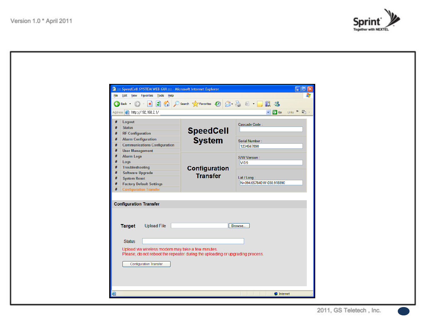
Configuration Transfer: Upload
• Uploading process of set values.
• Verify correct file is selected and click „Configuration Transfer‟.
68
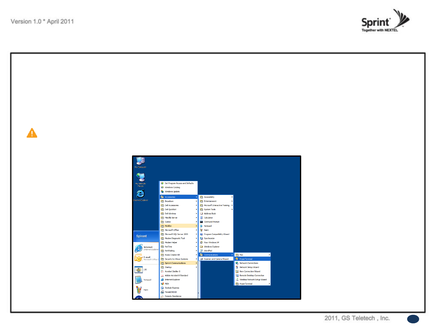
Command Line Interface (CLI)
CAUTION
RS-232 cable or USB to Serial conversion cable is not provided with the equipment.
After connection, you can access CLI using HyperTerminal.
• In case that you cannot reach Web UI, you should use CLI.
You should connect the equipment‟s CLI port to your laptop‟s serial port using RS-232 cable.
In case that your laptop does not have a serial port, you may need to use USB to Serial conversion cable.
• To open HyperTerminal, click “Start”, then “Accessories”, then “Communications”, then “HyperTerminal”.
69
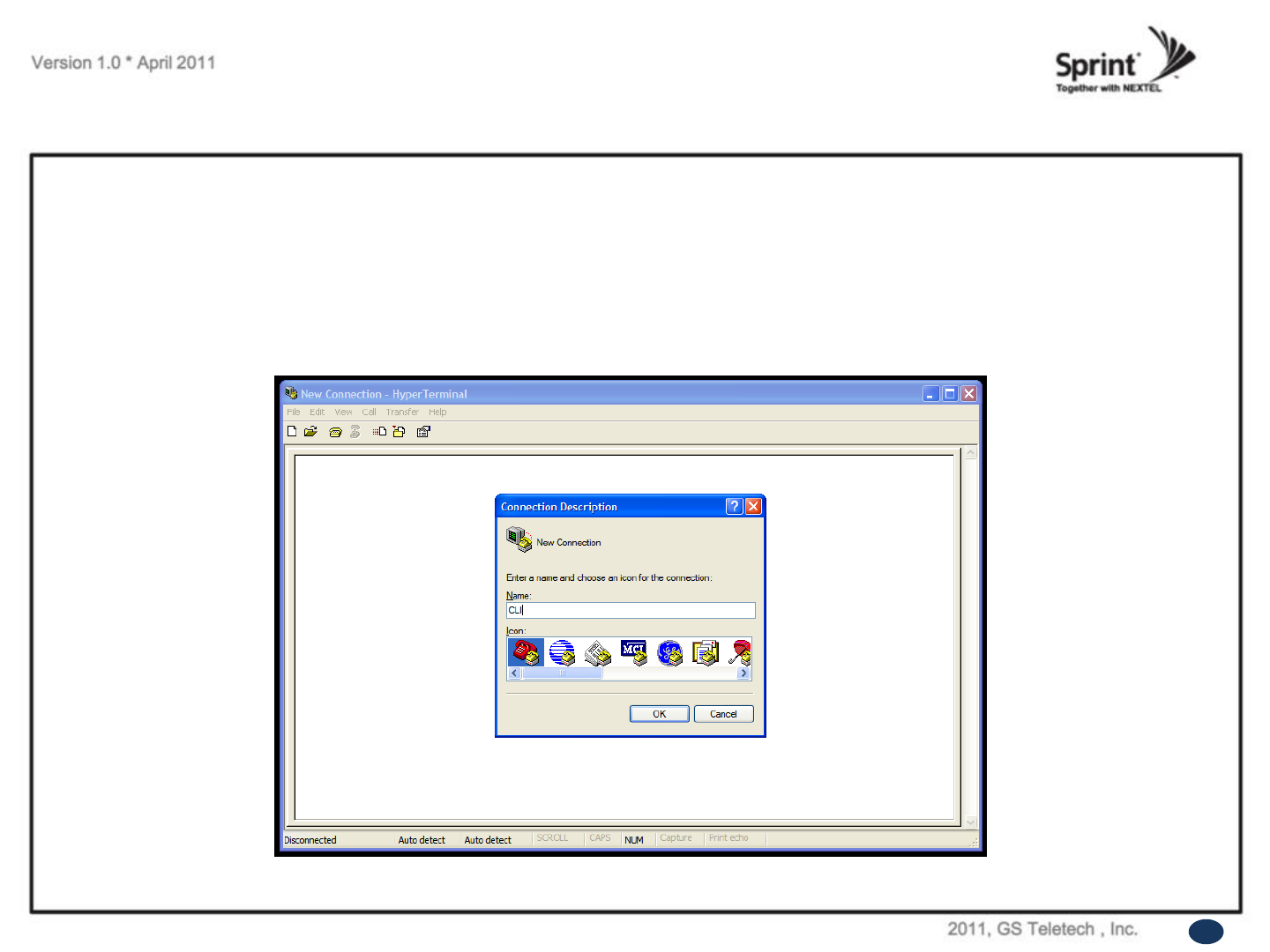
CLI
• To verify and/or change port number, open “Control Panel”, then “System”, then “Hardware Tab”,
then “Device Manager”. Double click “Ports”, then double click “Serial Cable” then click “Port Settings” tab, click “Advanced”, in
the COM Port drop down menu, select “COM 1”, click “OK”.
• After verification of port number, open HyperTerminal.
• Enter CLI.
• Click “OK”.
70
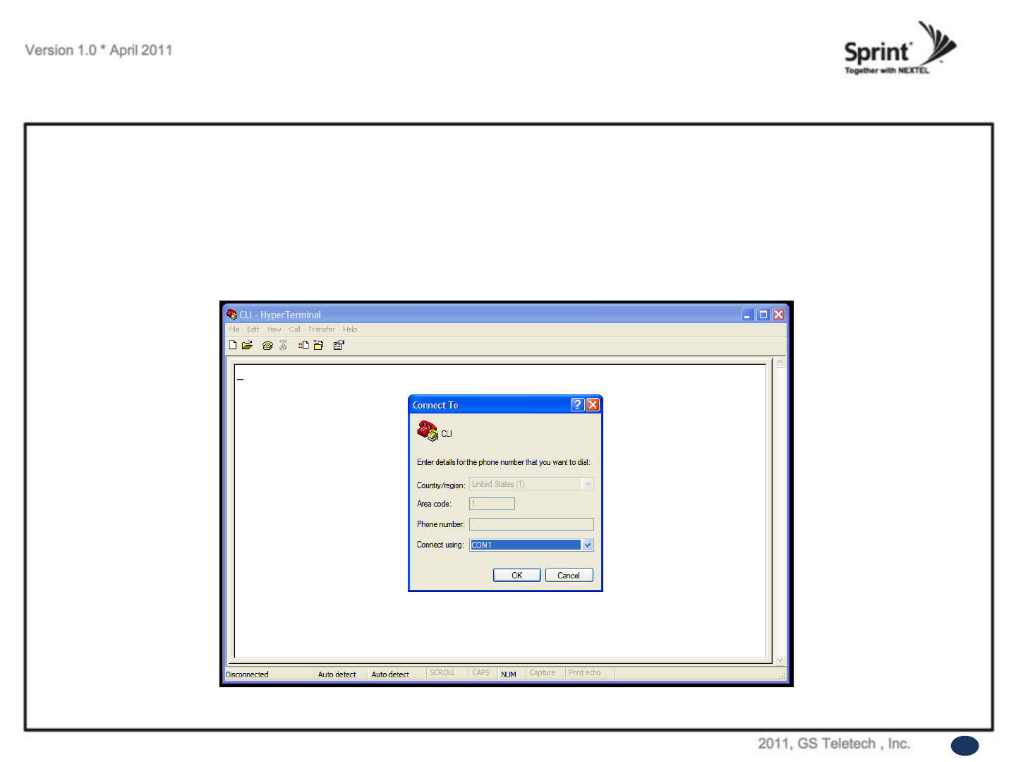
CLI
• In the “Connect using” drop-down menu, select “COM1”.
• Click “OK”.
71
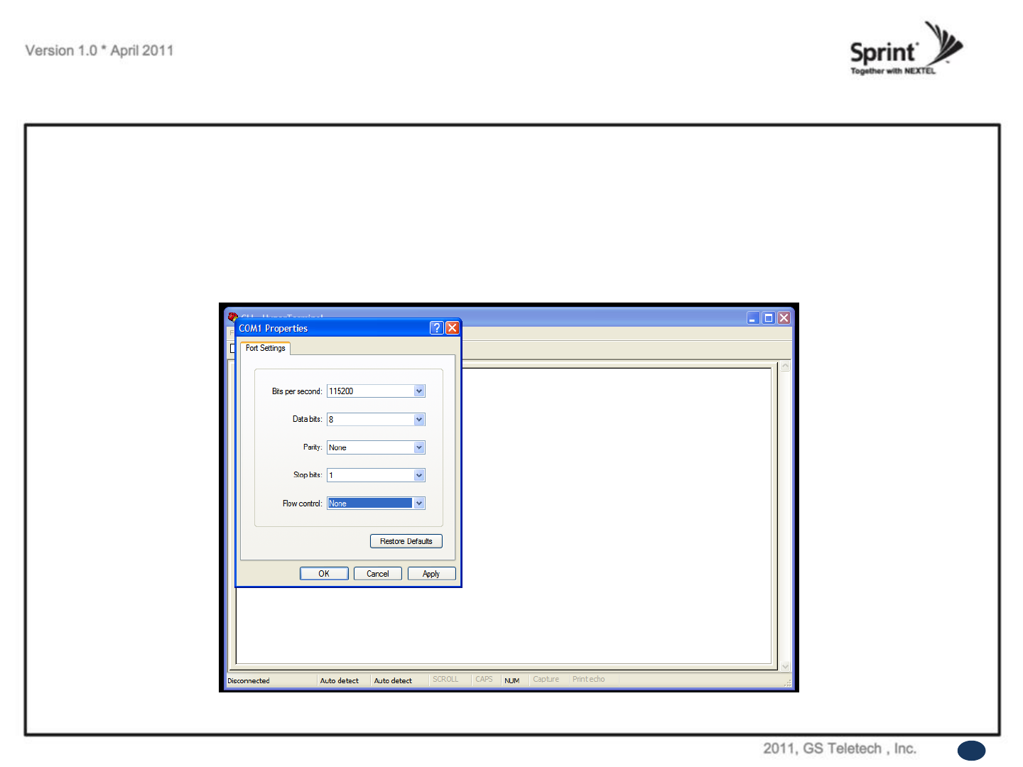
CLI
• “Bit per second” drop down menu, select “115200”.
• “Flow control” drop down menu, select “None”.
• Click “Apply”.
• Click “OK”.
72
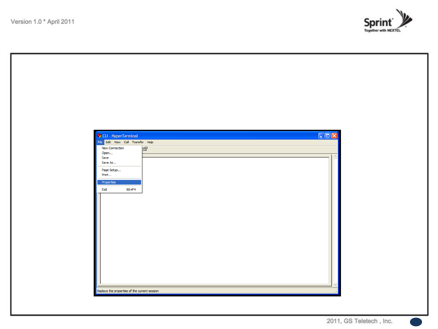
CLI
• Click “File”, choose “Properties”
73
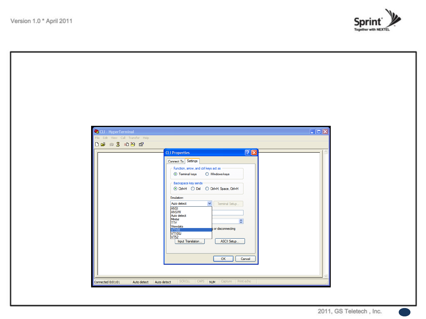
CLI
• On „Settings‟ tab.
• „Emulation‟ drop down menu, select „VT100‟.
• Click „OK‟.
74
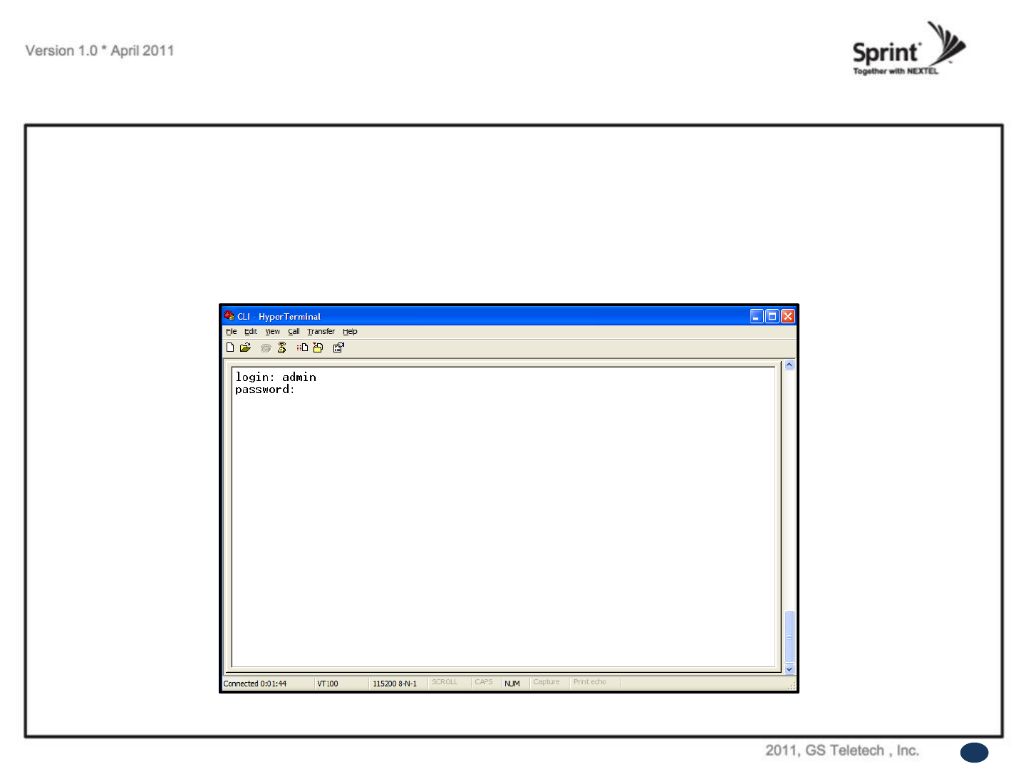
CLI
• In case that you cannot see login prompt, just press enter key several times.
Login is „admin‟ and Password is „admin‟.
75
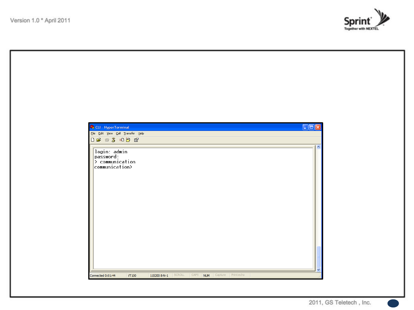
CLI
• In order to verify IP network configuration, you should type „communication‟.
• Press enter-key.
76
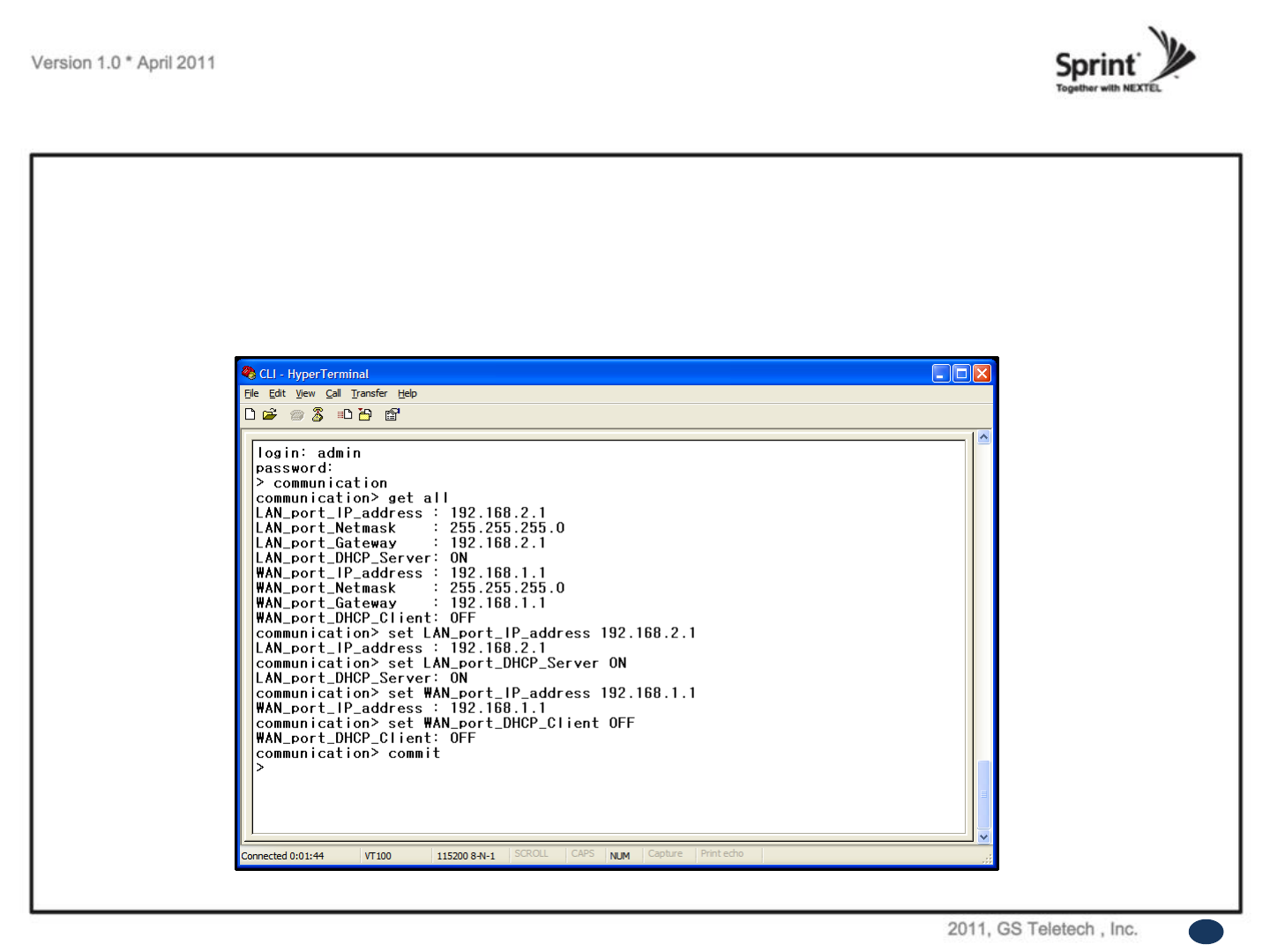
CLI
• In order to see values, you should type “get all”, and then press the enter-key.
• Enter the following text:
“set LAN_port_IP_address 192.168.2.1”, then press the enter-key.
“set LAN_port_DHCP_Server ON”, then press the enter-key.
“set WAN_port_IP_address 192.168.1.1”, then press the enter-key.
“set WAN_port_DHCP_Client OFF”, then press the enter-key.
“commit”, then press the enter-key.
77
GST Technical Support
Phone:
Toll Free: 1-866-9 GST USA
Phone: 913-469-6699
Write:
GS Teletech Inc.
6900 College Boulevard, Suite 850,
Overland Park, KS 66211, USA
Product Information and Technical Assistance:
www.gsteletechinc.com
support@gsteletechinc.com
Specifications and features of this installation guide are subject to change without notice or obligation.
78

© 2010, GS Teletech, Inc. 66
Warning: Exposure to Radio Frequency Radiation The radiated output power
of this device is far below the FCC radio frequency exposure limits.
Nevertheless, the device should be used in such a manner that the potential
for human contact during normal operation is minimized. In order to avoid
the possibility of exceeding the FCC radio frequency exposure limits, human
proximity to the antenna should not be less than 50cm
during normal operation. The gain of the antenna is 12 dBi.
The antenna(s) used for this transmitter must not be co-located or operating in
conjunction with any other antenna or transmitter.