GS Instech SMR-IP10-D In-Building RF Repeater User Manual
GS Instruments Co., Ltd. In-Building RF Repeater
User Manual
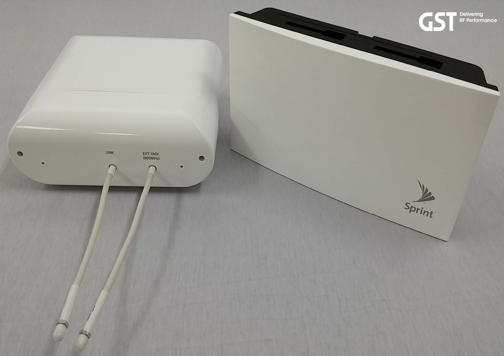
Technicians Installation & Operation Guide
Model: SMR-IP10-D
SMR-IP10-S
Version 1.0
GS Teletech Inc.
Confidential and proprietary to GS Teletech Inc.
Copying, reproduction or distribution this information is strictly prohibited
without prior written authorization from GST.

SMR-IP10-D/-S
Smart Mobile Repeater for 800MHz and 1900MHz Bands
Application: Small Business, Enterprise and Public venues.
Coverage: Up to 5k sq. ft. per unit.
SMR-IP10
Technician’s Installation & Operation Guide
This publication provides instructions for installing the 800MHz and 1900MHz Smart Mobile Repeater.
The images for the User Interface in this publication may vary depending on it’s S/W version.
Copyright
!"
Version History:
Certification
#$%&''()**+#$"&''
Date Version Changes
04/2015 1.0
SMR-IP10
,
Technician’s Installation & Operation Guide
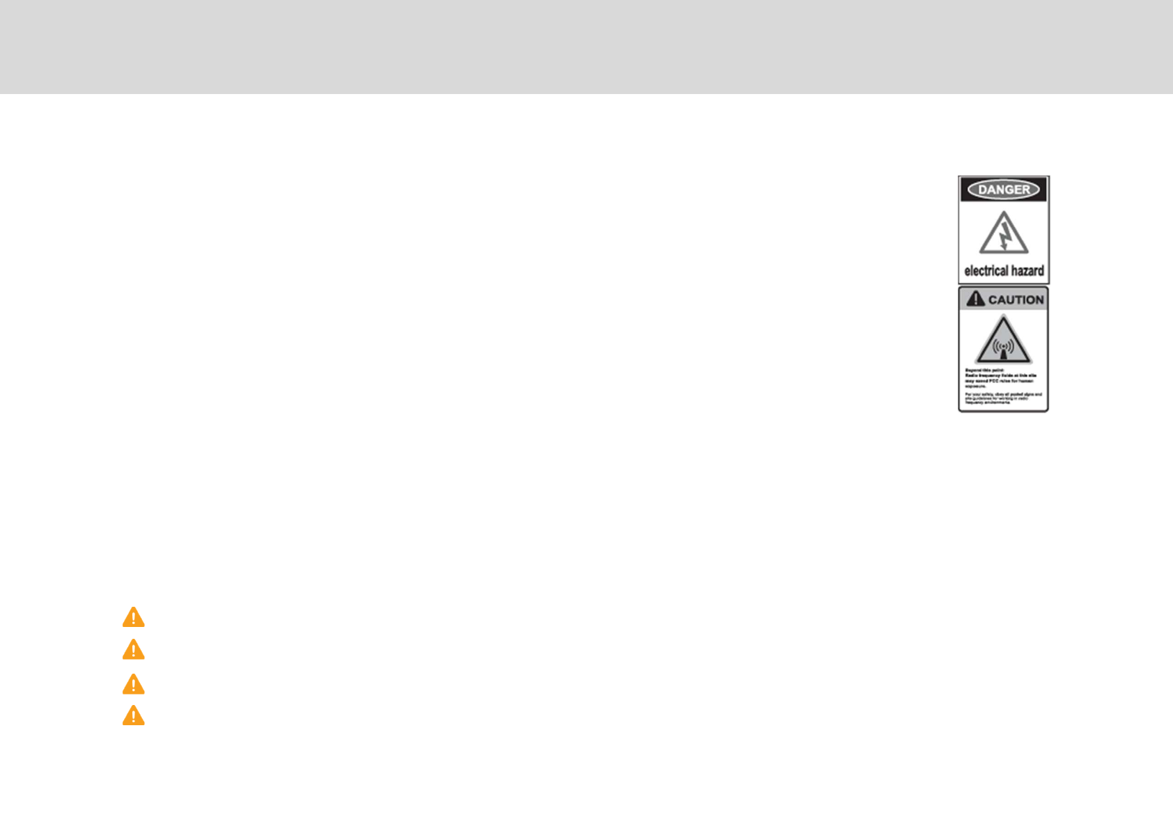
WARNING! EXPOSURE TO RF
Working with the repeater while in operation, may expose the technician to RF electromagnetic fields
that exceed FCC rules for human exposure. Visit the FCC website at http://www.fcc.gov/oet/rfsafety
to learn more about the effects of exposure to RF electromagnetic fields.
WARNING! ELECTRIC SHOCK
Opening the BDA (bi-directional amplifier) could result in electric shock and may cause severe injury.
WARNING! DAMAGE TO EQUIPMENT
Operating the BDA with antennas in very close proximity facing each other could lead to severe damage
to the repeater.
RF EXPOSURE & ANTENNA PLACEMENT
Actual separation distance is determined upon gain of antenna used.
Please maintain a minimum safe distance of at least 8 inch while operating near the donor and the server antennas. Also,
the donor antenna needs to be mounted outdoors on a permanent structure.
WARRANTY
Opening or tampering the BDA will void all warranties.
CAUTION: REPEATER SHOULD BE INSTALLED AS CLOSE AS POSSIBLE TO POWER SOURCE.
CAUTION: THIS REPEATER IS FOR INDOOR USE ONLY AND SHOULD BE LOCATED INSIDE OF BUILDING.
CAUTION: RISK OF EXPLOSION IF BATTERY ON CONTROLLER BOARD IS REPLACED WITH AN INCORRECT TYPE.
CAUTION: DISPOSE OF USED BATTERIES ACCORDING TO THE INSTRUCTIONS.
Warnings and Hazards
-
Technician’s Installation & Operation Guide

This equipment has been tested and found to comply with the limits for a Class B digital device, pursuant to part 15 of the FCC
Rules.
These limits are designed to provide reasonable protection against harmful interference in a residential installation. This equipment
generates, uses and can radiate radio frequency energy and, if not installed and used in accordance with the instructions, may
cause harmful interference to radio communications. However, there is no guarantee that interference will not occur in a
particular installation. If this equipment does cause harmful interference to radio or television reception, which can be determined
by turning the equipment off and on, the user is encouraged to try to correct the interference by one or more of the following
measures:
- Reorient or relocate the receiving antenna.
- Increase the separation between the equipment and receiver.
- Connect the equipment into an outlet on a circuit different from that to which the receiver is connected.
- Consult the dealer or an experienced radio/TV technician for help.
FCC Part 15.21 statement
Any changes or modifications not expressly approved by the party responsible for compliance could void the user's authority to
operate this equipment.
RF Exposure Statement
The antenna(s) must be installed such that a minimum separation distance of at least 20 cm is
maintained between the radiator (antenna) and all persons at all times. This device must not be co-located or operating in
conjunction with any other antenna or transmitter.
Part 90.635 requirement
Antennas must be installed in accordance with FCC 90.635. With 9 dBi gain antennas the height of the antenna above average
terrain (HAAT) is permitted over 1372m. For different gain antennas refer to the relevant rules.
Warnings and Hazards
Technician’s Installation & Operation Guide
WARNING. This is NOT a CONSUMER device. It is designed for installation by FCC LICENSEES and QUALIFIED
INSTALLERS. You MUST have an FCC LICENSE or express consent of an FCC Licensee to operate this device.
Unauthorized use may result in significant forfeiture penalties, including penalties in excess of $100,000 for each
continuing violation.
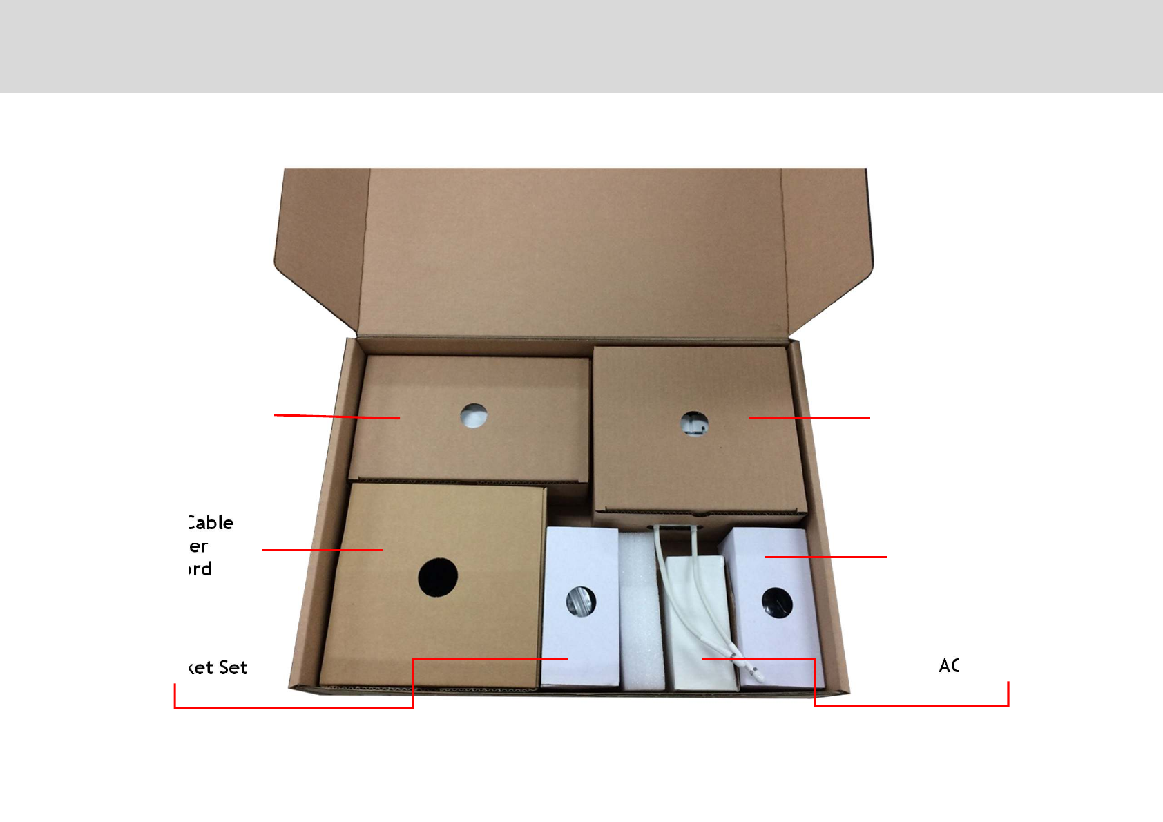
Link Cable
Jumper
AC Cord
DAU Bracket Set AC/DC Adaptor
Contents of Box (1/2)
.
Technician’s Installation & Operation Guide
SAU Bracket Set
DAUSAU
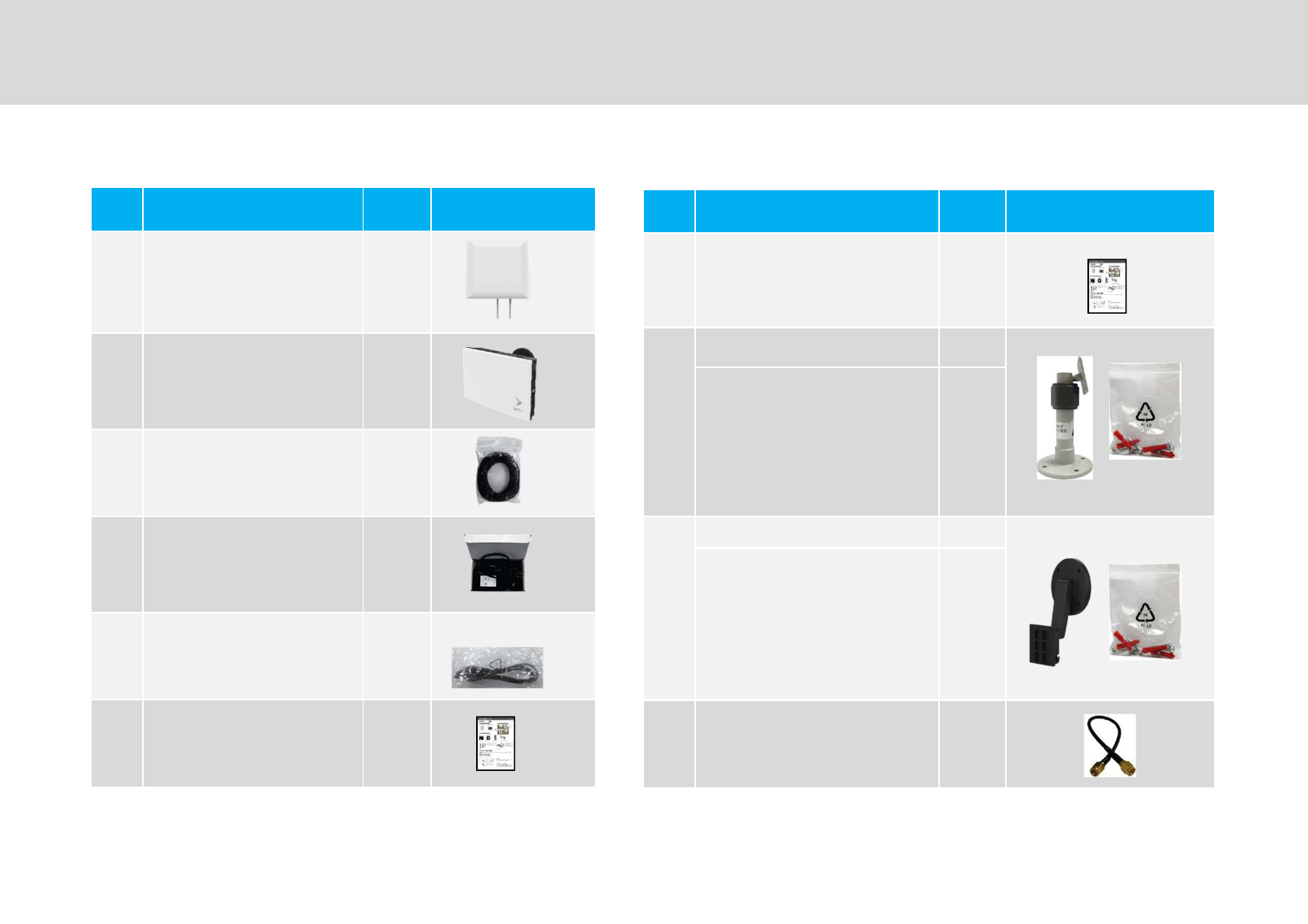
No Item Q-ty Picture
/"#
0/#1
"#
0#1
,$2"0/1*
-'%/'"
'+'
.32""
No Item Q-ty Picture
45""
6
/#7"2
8 "+
090:1;<1
8
-
=
#7"2
8"+
090:1;<1
-
>*'"
6?9@"
=?@
Contents of Box (2/2)
4
Technician’s Installation & Operation Guide
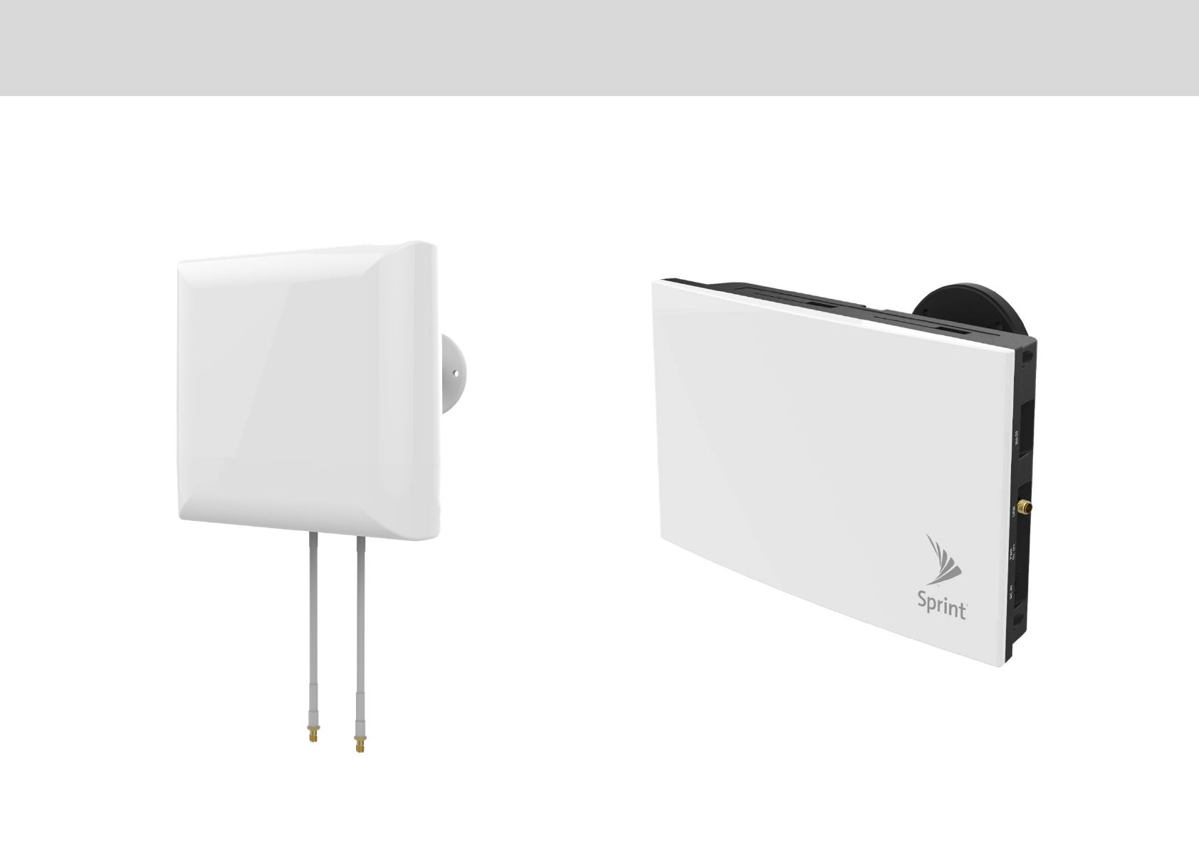
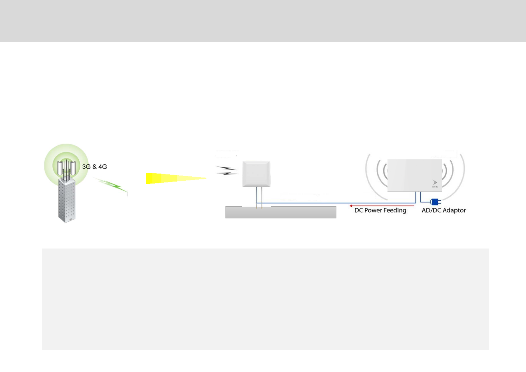
Donor Antenna Unit (DAU) Service Antenna Unit (SAU)
Repeater Design
6
Technician’s Installation & Operation Guide
SMR-IP10-D SMR-IP10-S
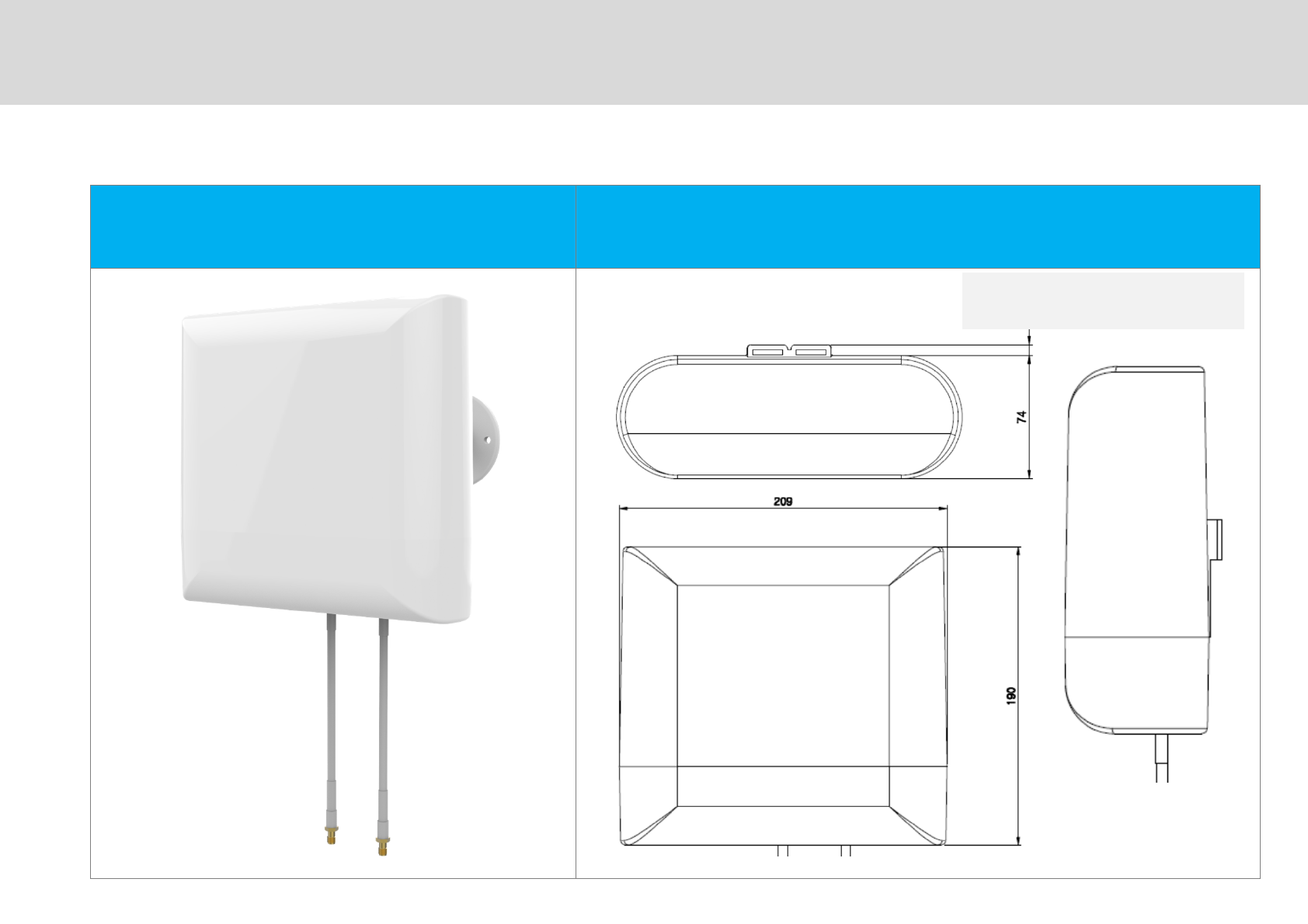
DAU (SMR-IP10-D) Dimensions
=
Technician’s Installation & Operation Guide
=0A1<=091<4-0/1B**C
60A1<4-091<=0/1BC
Repeater Design: Donor Antenna Unit (DAU)
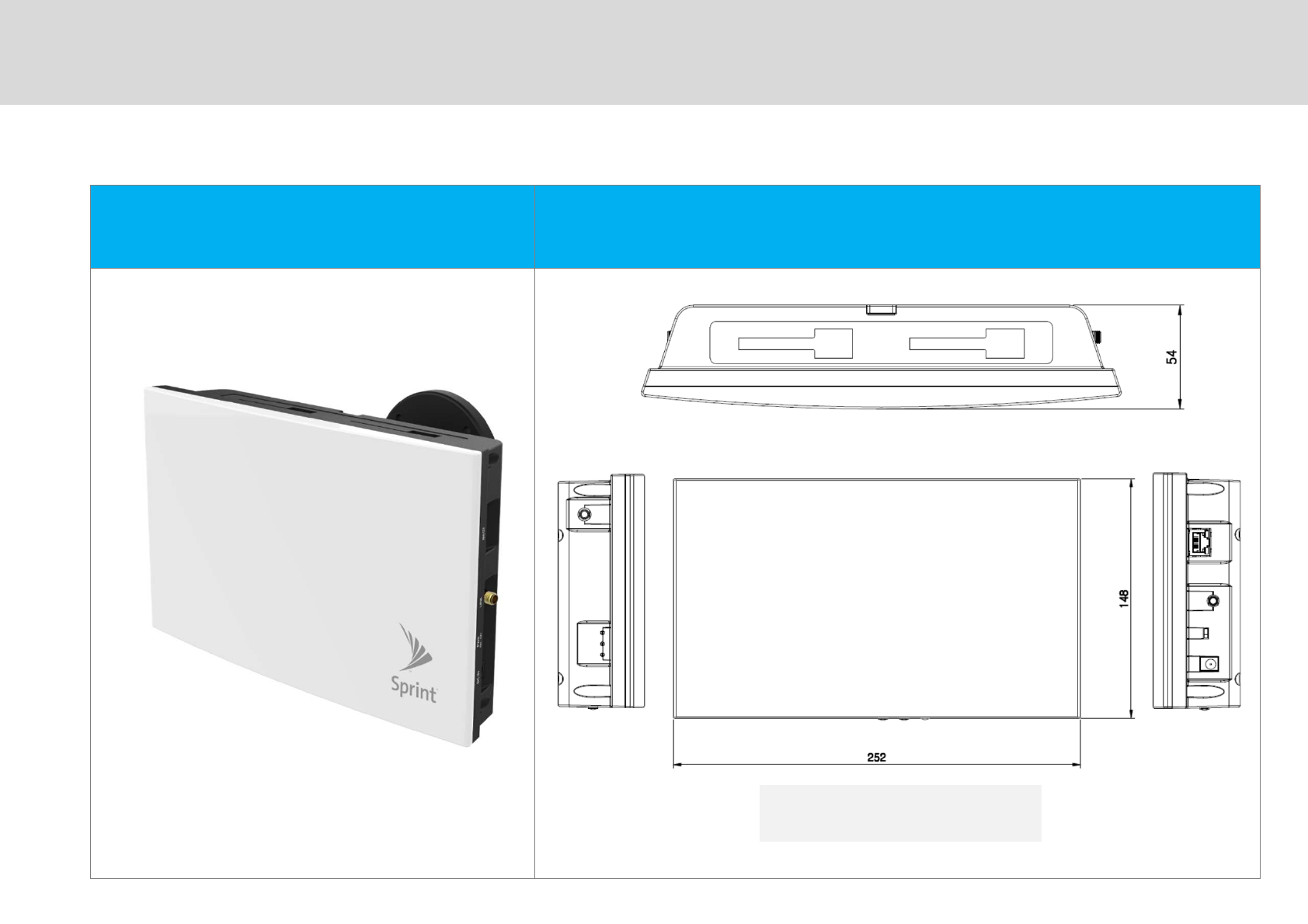
SAU (SMR-IP10-S) Dimensions
Technician’s Installation & Operation Guide
0A1<-6091<-0/1B**C
==0A1<6091<0/1BC
Repeater Design: Service Antenna Unit (SAU)
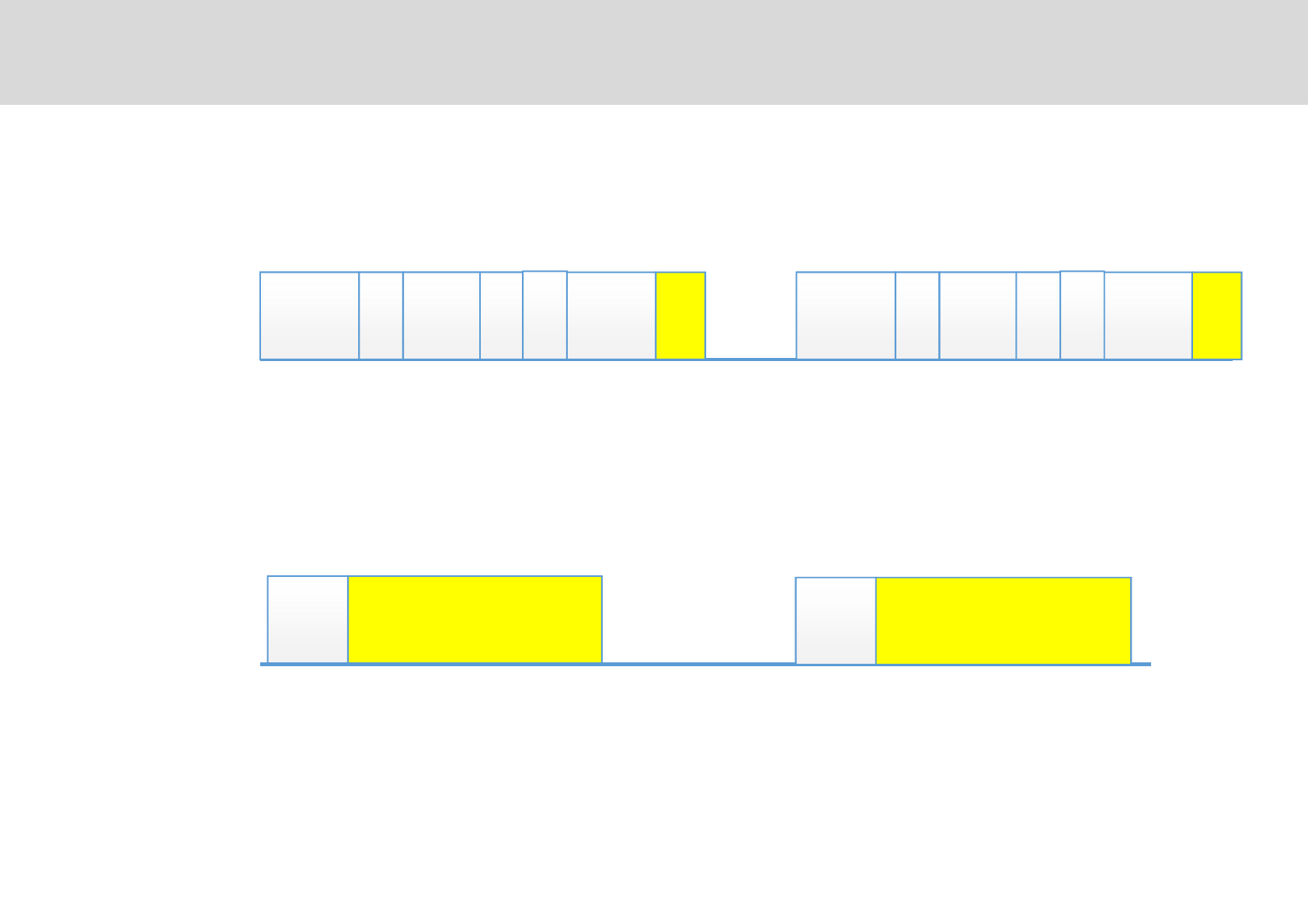
800MHz & 1900MHz Frequency Bands
Technician’s Installation & Operation Guide
Service Band Blocks
800MHz Band
1900MHz Band
817 824 869
862
A D BE F CGA D BE F CG
1850 1910 1915 1930 1990 1995
LTE
819 864
CDMA CDMA LTE
7D""/"#0/#1""#0#1
$2/"(*0 */##14-0/1"0ED&"**"1
F/'+ *"#/"#
F"G %%?9@""A#
*'%E0'"E1"E&0E&1
H "G0*"&1
"
6?9@H=?9@
Introduction
/# #
4-'"0ED&"**"1
Technician’s Installation & Operation Guide
?D""" "/"#0/#1"""#
0#1?D""+"*"I** -""I"""
""2 *#"+I""""
017 ?D"2""2
""*@"*""G
Main Features

Installation Guideline
,
Technician’s Installation & Operation Guide
Donor Antenna Unit (DAU)
/"#0/#1JG*""""" *""
&""+&"*"""/#
6?9@"=?9@7" "6?9@"+"20"D=7*1"
*"G/#6?9@I""" ""*" *6?9@7"
"
'2*"*""A#
"/#" "+""G"
/"/##"""**0F"1
/"""" "0+ 1
/""""*"
/""I09". 1

-
Technician’s Installation & Operation Guide
"#0#1" """
"+/"#""#"
"#+"
"#""+""G"
" +"" G"#""""
Installation Guideline
Service Antenna Unit (SAU)
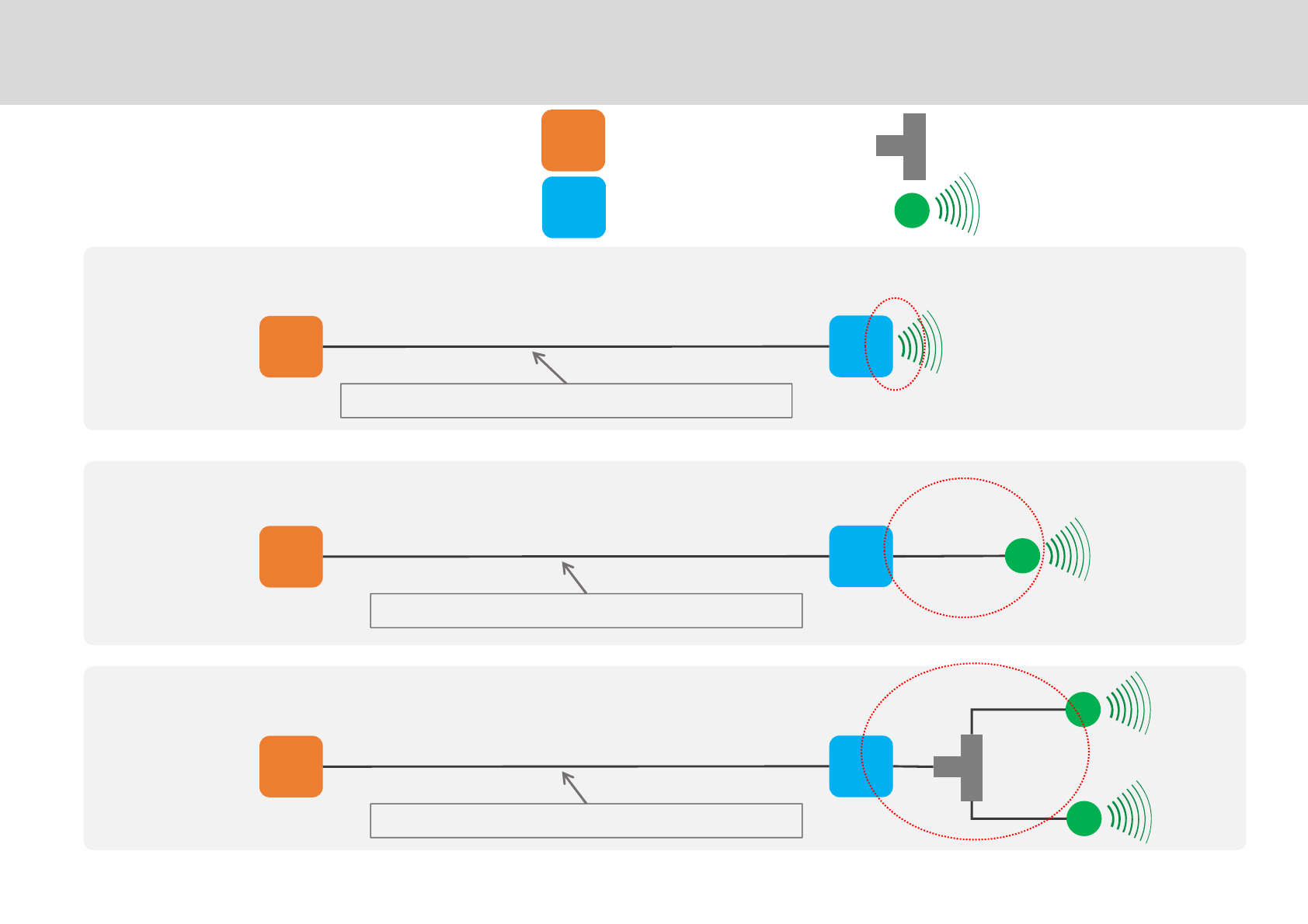
Technician’s Installation & Operation Guide
Application
Donor Antenna Unit
Service Antenna Unit Service Antenna
Divider (Splitter)
Basic Structure (Recommended)
Link Cable Loss consideration is necessary if extended
1 External Antenna
Built-in antenna
2 External Antenna
Link Cable Loss consideration is necessary if extended
Link Cable Loss consideration is necessary if extended
Cable Loss should be considered
Cable Loss should be considered
Installation Guideline
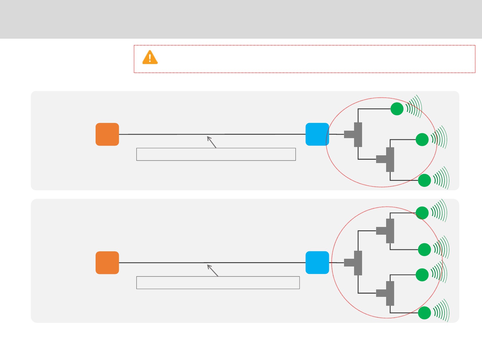
.
Technician’s Installation & Operation Guide
Application
3 External Antennas
Link Cable Loss consideration is necessary if extended
4 External Antennas
Link Cable loss consideration is necessary if extended
Cable Loss should be considered
Cable Loss should be considered
When using 4 dividers, the following architecture will be applicable and the divider shall stay the same.
When using 3 dividers, the longest cable should be connected to the first divider for equalization of the EIRP)
Installation Guideline
4
Technician’s Installation & Operation Guide
I """++" ""
+"+#2"+2"+"#2"
&I"*+" /"#0/#1D=7*""*"
"G*"2"7
/
0I1 '" "
0+#""1
≧D47*
≦* ≦7
≦,* ≦7
≧D67*
≦* ≦7
≦,* ≦7
≧D67*
≦* ≦7
≦,* ≦7
≧D=7*
≦* ≦7
≦,* ≦7
≧D=7*
≦* ≦7
≦
,* 7
Installation Guideline
Coverage Area – CDMA 1X RSSI
6
Technician’s Installation & Operation Guide
Coverage Area - LTE
/+2"#2"*""6K *"*
Post-Installation Measurement (Retail/Sales Area)
EVDO 800 MHz 1900 MHz
/$0?%1 E% 56K *"*
#$0?%1 E% 56K *"*
LTE 800 MHz 1900 MHz
/$0?%1 56K *"* 56K *"*
#$0?%1 56K *"* 56K *"*
Installation Guideline
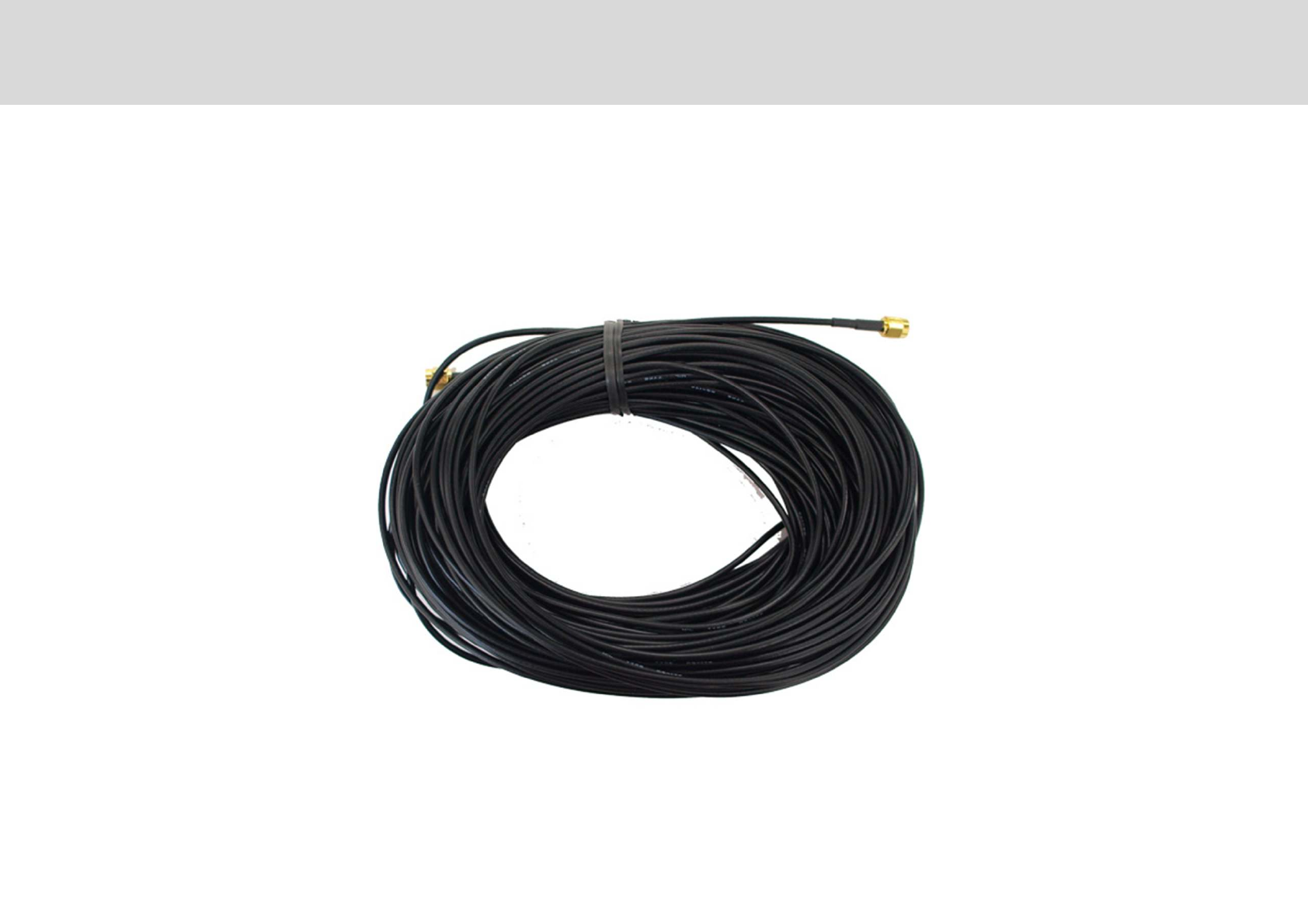
Cable Length: 50m (164 ft.)
=
Technician’s Installation & Operation Guide
Link cable
Installation Guideline
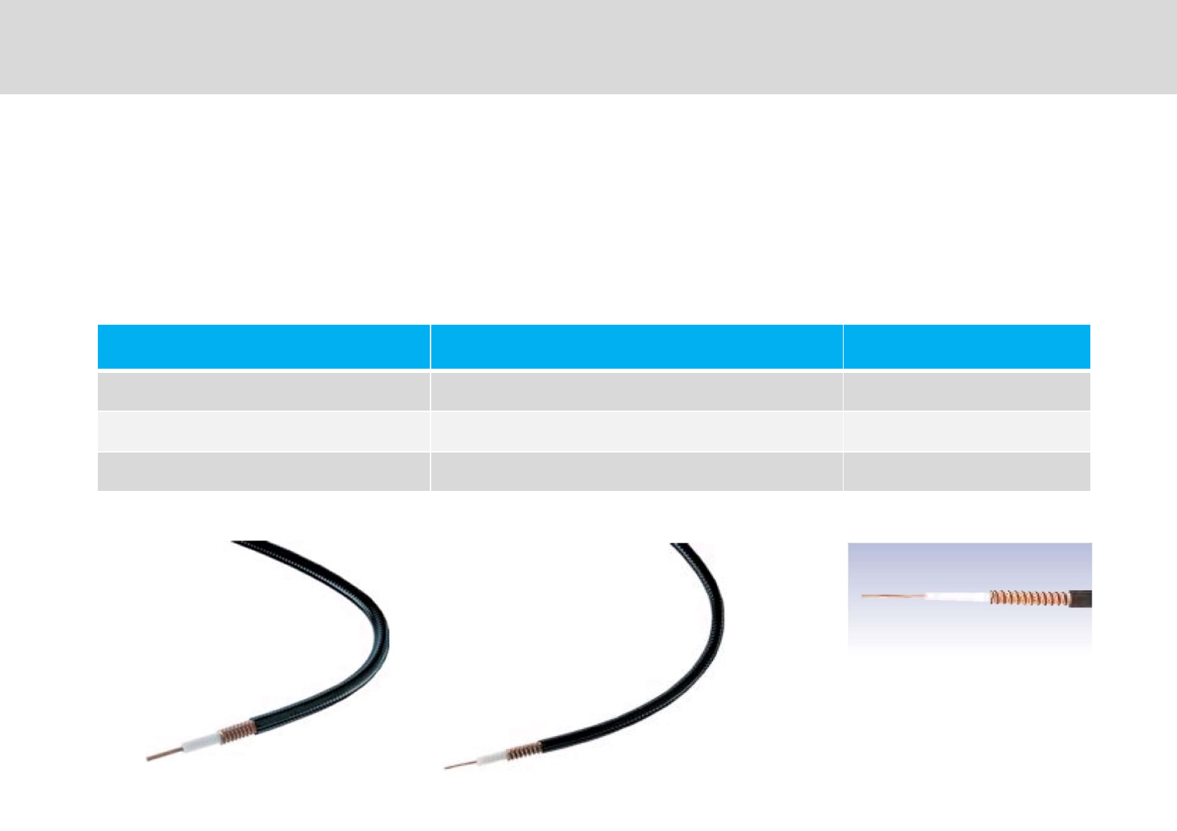
Cable Type Link Distance Remark
%6'"I"'" 50m (164ft) ~ 100m (328ft) I*"G
%-'"I"'" 100m (328ft) ~ 180m (590ft) I*"G
,%6'"I"'" 180m (590ft) ~ 270m (885ft) I*"G
%-L
'"I"'"0*1
,%6L
'"I"'"0*1
%6L
'"I"'"0*1
BG**C
/'/(E*0'%/'"0/'1(:=M1 +"
'"$ "(9dB ~ 15dB (Mandatory)
Technician’s Installation & Operation Guide
Link Cable Extension
Installation Guideline
Measurement Criteria
Technician’s Installation & Operation Guide
G0 1
I'/? 6?9@ =?9@
E Serving Physical Cell Identity Serving Physical Cell Identity
07*1 D=7*" D=7*"
F%071 D7" D7"
FM/5 6?9@ =?9@
E E% Serving Physical Cell Identity
07*1 E% D=7*"
F%071 E% D7"
$F 6?9@ =?9@
' Serving Physical Cell Identity Serving Physical Cell Identity
07*1 D7*" D7*"
3071 D67 D67
Site Survey (Roof): Conditions for DAU Positioning
Technician’s Installation & Operation Guide
Site Survey (Service Target Area)
1x CDMA 800 MHz 1900 MHz
E Serving Physical Cell Identity Serving Physical Cell Identity
07*1 D=7* D=7*
EVDO 800 MHz 1900 MHz
E E% Serving Physical Cell Identity
07*1 E% D=7*
LTE 800 MHz 1900 MHz
' Serving Physical Cell Identity Serving Physical Cell Identity
07*1 D7* D7*
SMR-IP10 shall be installed even if one of the following 1x CDMA, EVDO and LTE criteria's are satisfied .
Site Survey (Target Area): Conditions for SAU Positioning
Measurement Criteria
,
Technician’s Installation & Operation Guide
Post-Installation Measurements (Retail/Sales Area)
1x CDMA 800 MHz 1900 MHz
E Serving Physical Cell Identity Serving Physical Cell Identity
07*1 D67*" D67*"
F%071 D7" D67"
?<+ 7*
EVDO 800 MHz 1900 MHz
E E% Serving Physical Cell Identity
07*1 E% D67*"
F%071 E% D67"
?<+ E% 7*
/$0?%1 E% 56K *"*
#$0?%1 E% 56K *"*
LTE 800 MHz 1900 MHz
' Serving Physical Cell Identity Serving Physical Cell Identity
07*1 D67*" D67*"
3071 D67 " D67 "
?<+ 7* 7*
/$0?%1 56K *"* 56K *"*
#$0?%1 56K *"* 56K *"*
Measurement Condition: More than 80% of coverage area
Post-installation (Service Area):
Measurement Criteria
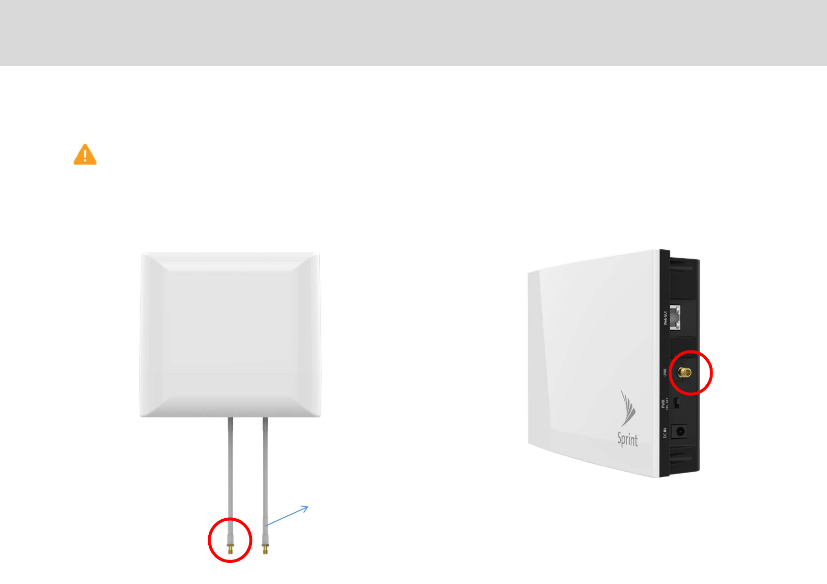
[DAU Link port]
800MHz External antenna connection (If required)
[SAU Link Cable port]
CAUTION
/" *E++5E
Cable Connections
Technician’s Installation & Operation Guide
-
Link Cable Ports
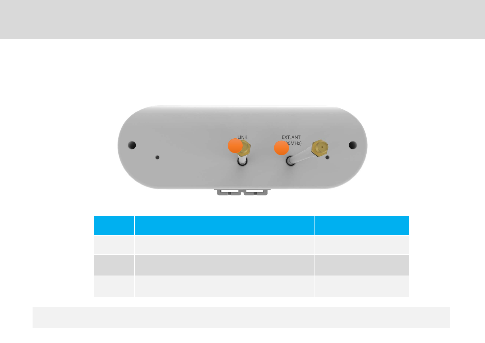
No Port Connector
$2'" ?0&1
6?9@"
0 )1 ?0&1
76?9@"=?9@"
0 I*G)1 ?0&1
[DAU Bottom Side]
Repeater Port Design
Technician’s Installation & Operation Guide
Donor Antenna Unit
""/#JF<E"+"""" 6?9@"=?9@
" ", N>*J*"" *""G
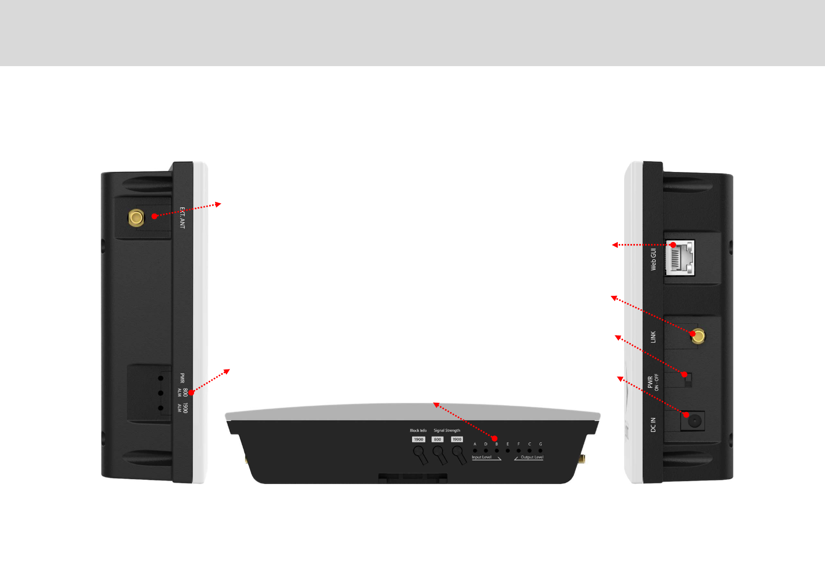
$F/"
0+%"*1
FI""
A#
0>-1
$2'"'
+5%5
'%/'"
B$ C BC
$F/"
07" *"
H"1
B7*C
Repeater External Port Design
.
Technician’s Installation & Operation Guide
Service Antenna Unit
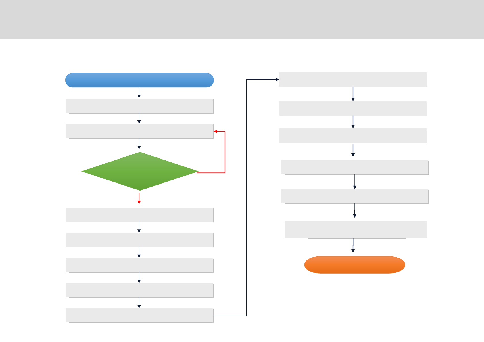
Setup
Start ‘WebGUI’
Band Selection & Alarm Check
More than -95dBm
Input Signal Checking
DAU Mounting
Link Cable Connection
Cabling to SAU
SAU Mounting
AC outlet construction
Link Cable Connection
AC/DC Adaptor Connection
SAU Switch On
Check LED Status
&
YES
Locate the DAU & SAU positions
NO
"
4
Technician’s Installation & Operation Guide
7
7
7
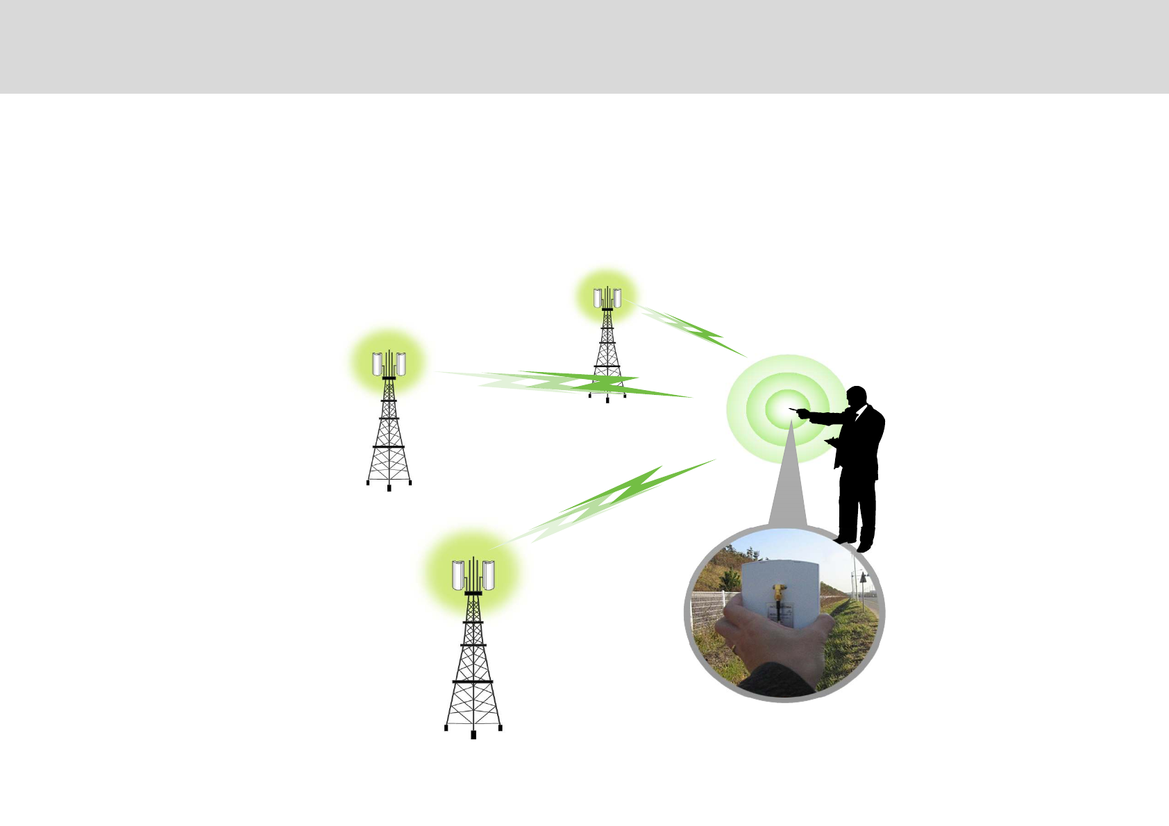
Positioning of DAU
6
Technician’s Installation & Operation Guide
Search for the proper BTS location
Please refer to ‘Measurement Criteria’ .
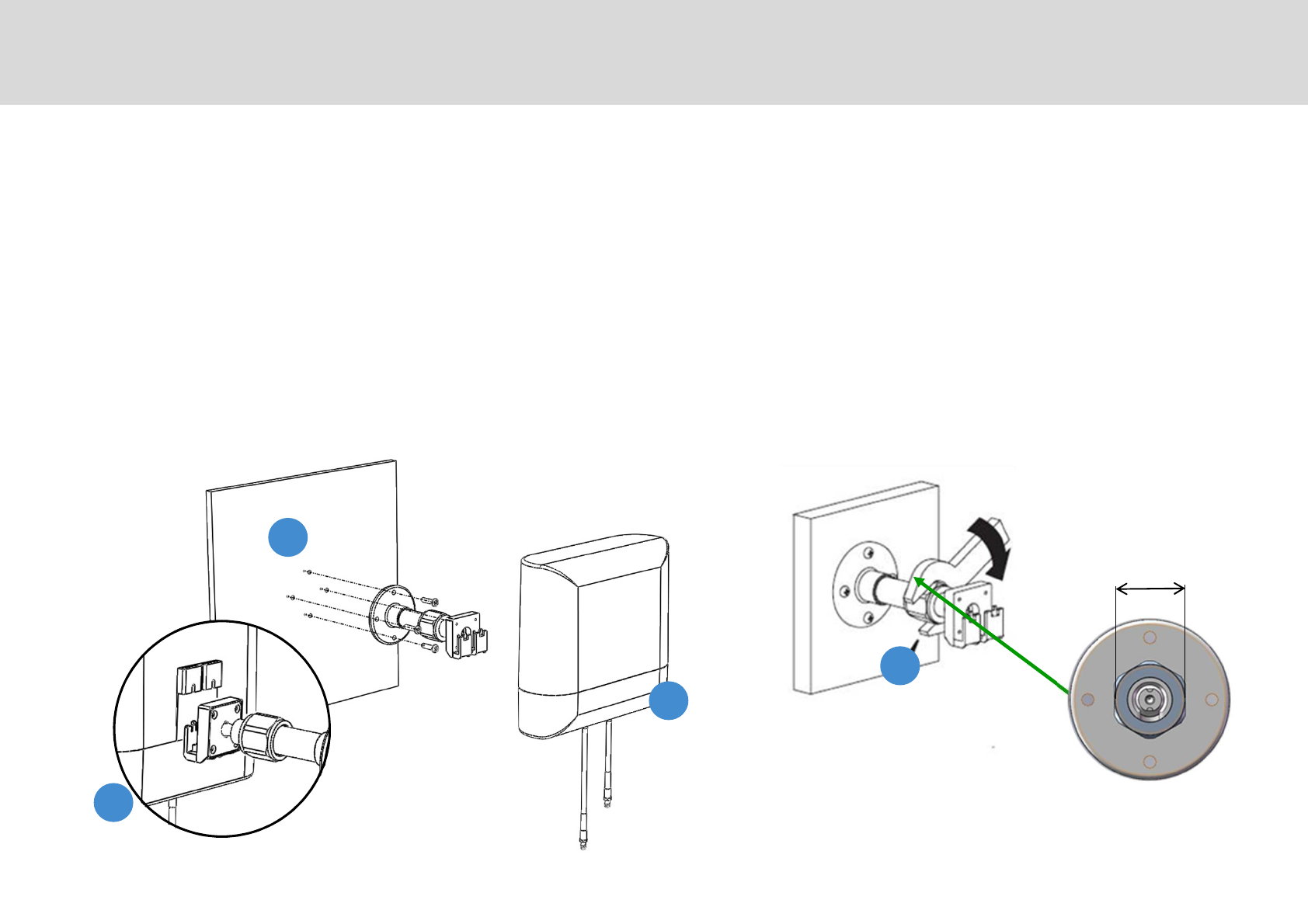
Donor Antenna Unit (DAU)
&""+$F" *7""
#"*"2" " /#7"2J *+"
,/+"""*"2
-"+""2""+
/#*"2
.*"2+"+0,**1
4'2"/#
-
,
32mm
Mounting SMR-IP10
=
Technician’s Installation & Operation Guide
/#"+"" 7"""""'/?%$F"
Mounting SMR-IP10
,
Technician’s Installation & Operation Guide
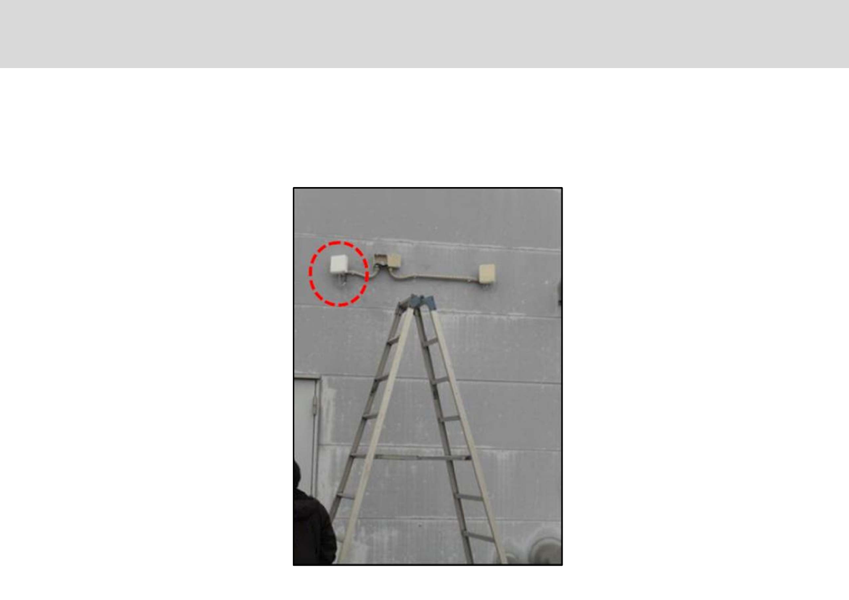
Installed DAU Example.
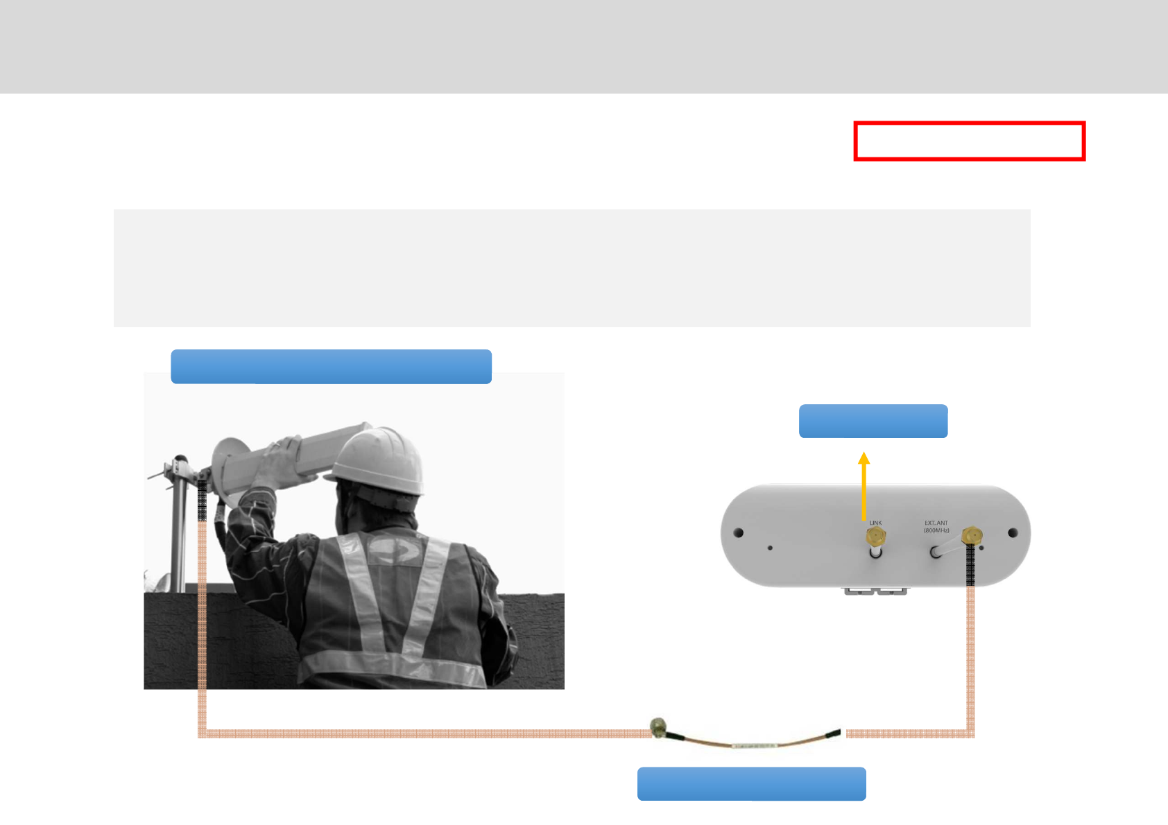
Jumper cable (Optional)
[DAU Bottom]
Link cable
800MHz Antenna (Optional)
※/7""J" 6?9@"=?@
'"(/#""5G0**1
"(/#0**1 )"6?9@""
)
External Antenna Installation for 800MHz.
,
Technician’s Installation & Operation Guide
GS Teletech, Inc.
Installed DAU and 800MHz External antenna
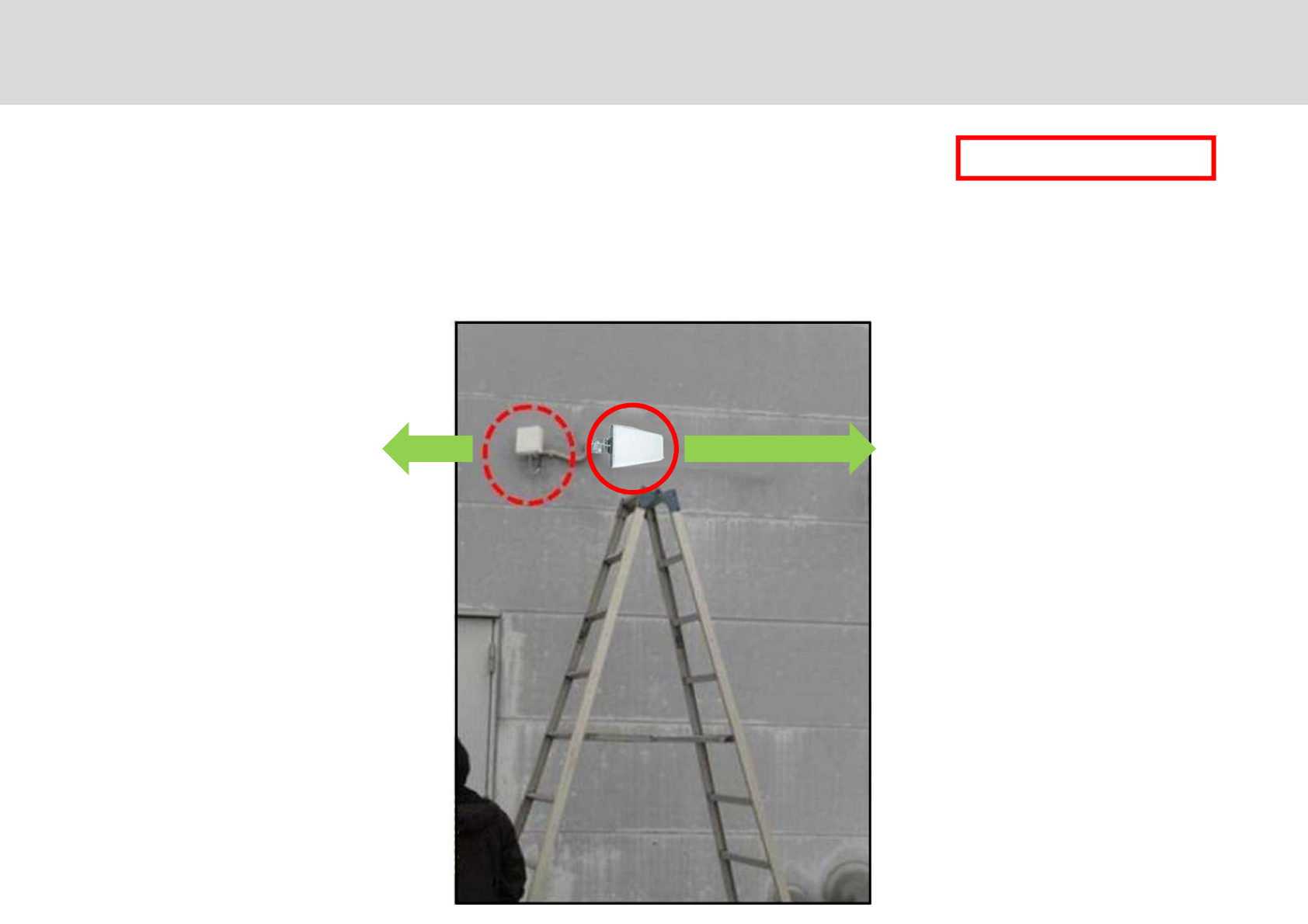
I"""+"7""071 *"7
6?9@"=?9@+2
DAU
6?9@FI""
/ =?9@7 / 6?9@7
)
,
Technician’s Installation & Operation Guide
Installed DAU and 800MHz External antenna
External Antenna Installation for 800MHz.
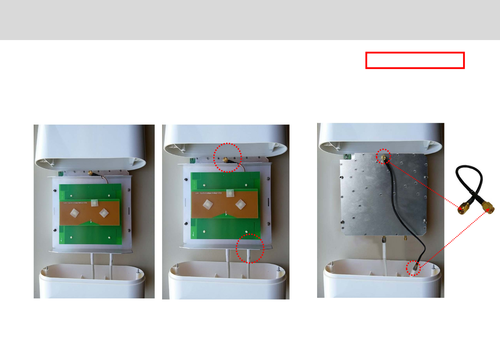
The Dual band antenna port for both 800MHz and 1900MHz should be connected with a jumper cable.
"*"2""/#*
Upgrading Existing Repeater With SMR-IP10
"G
,,
Technician’s Installation & Operation Guide
Jumper cable connection for adapting both 800MHz and 1900MHz
5/# $+ ,'O*"
6?9@E$2'"
For replacing an existing repeater
6?9@"=?9@
Jumper
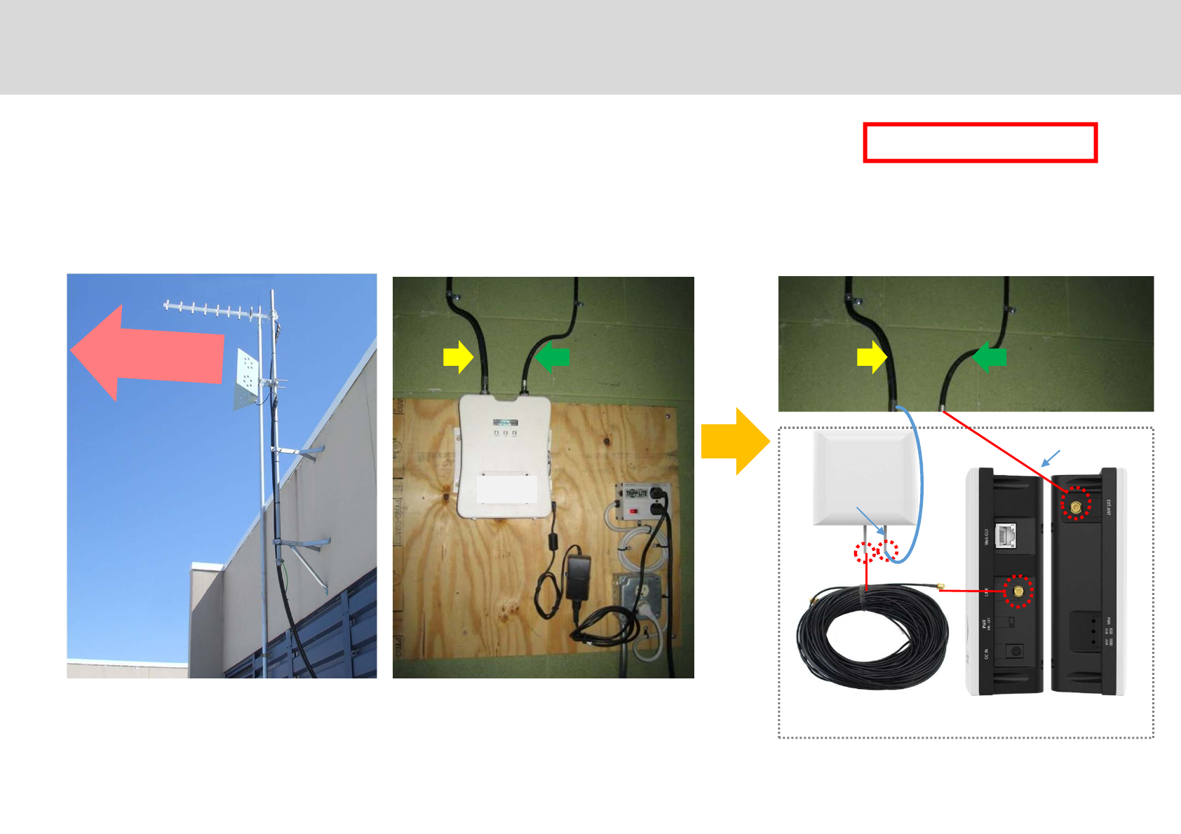
You may save cabling time and labor costs by using existing Donor Antenna and cable to existing Repeater
"G
,-
Technician’s Installation & Operation Guide
Existing Donor Antenna Connection and Replacement of existing Repeater
GS Teletech, Inc.
Upgrading Existing Repeater With SMR-IP10
Replacement of existing repeater
FI/" 6?9@"=?9@
800MHz & 1900MHz
Donor Antenna Service Antenna Donor Antenna Service Antenna
Donor Antenna
Left side
(SAU)
Right side
(SAU)
Link Cable Connection
Input Signal
Output Signal
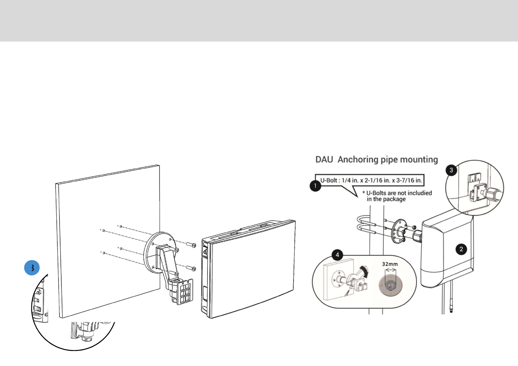
Service Antenna Unit (SAU) – Wall-Mounting
#"*"2" " #7"2J *+"
/+"""*"2
,"+""2""+
-#*"2
*"2+"+
.'2"#
,
Mounting The SAU
,
Technician’s Installation & Operation Guide
GS Teletech, Inc.
※#+D'/?%$F""
Service Coverage and Quality
,.
Technician’s Installation & Operation Guide
Service Quality Measurement
Please refer to ‘Measurement Criteria’
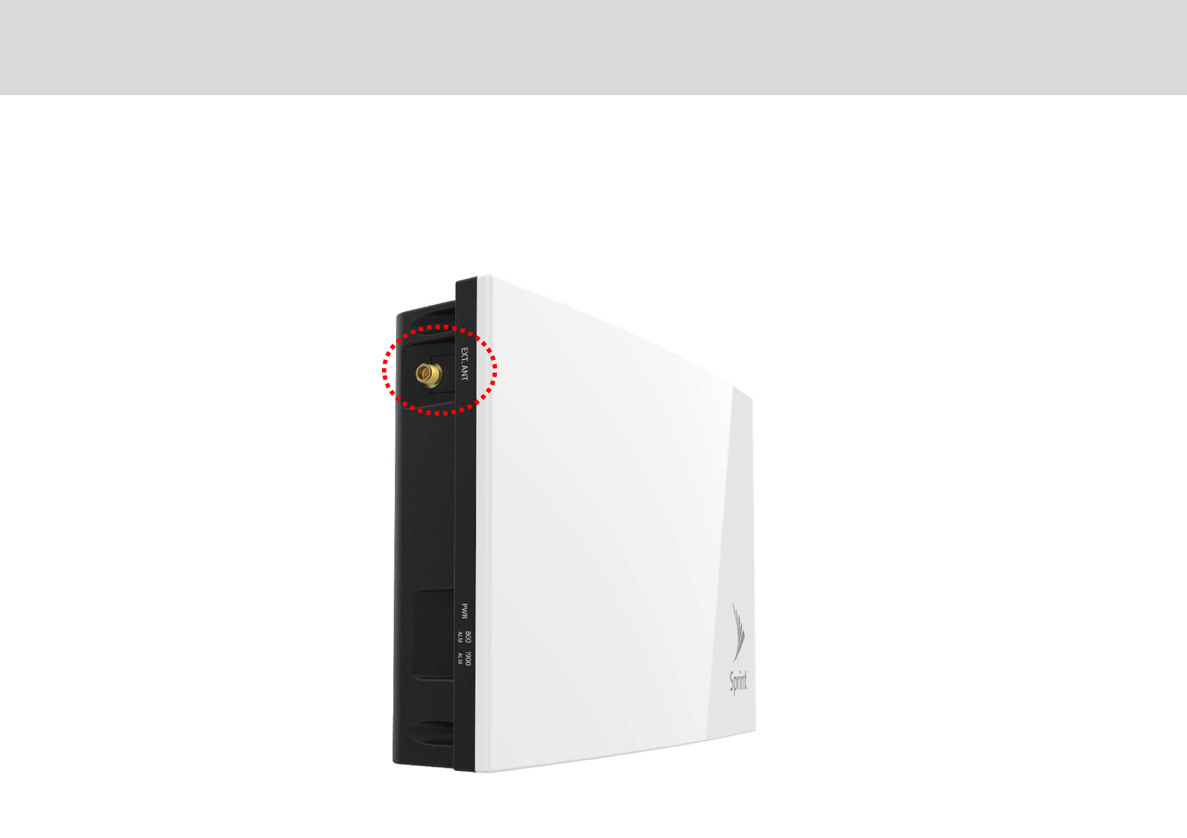
I"""""I"""J5
I""""#""+"
External Port of SAU
,4
Technician’s Installation & Operation Guide
External Antenna Port
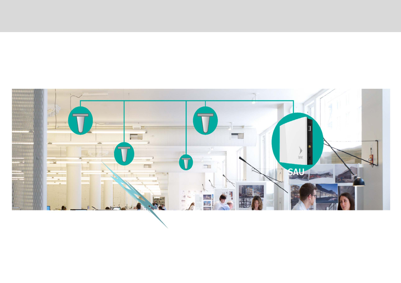
Service and Quality
,6
Technician’s Installation & Operation Guide
Service Quality Measurement
GS Teletech, Inc.
※#+DI'/?%$F""
Please refer to ‘Measurement Criteria’
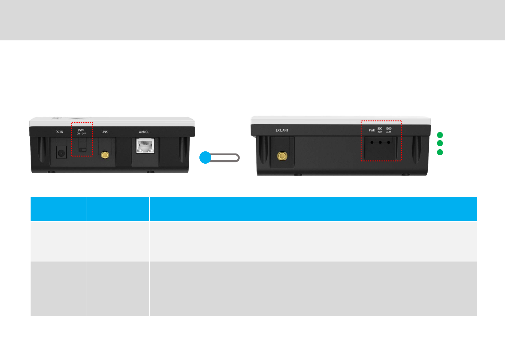
,=
Technician’s Installation & Operation Guide
No Item LED Indication Description
'2 FFE$F/72)
0A→=→61
E*"
A→FFE$F/5E
"*P=→FFE$F/5E
"*P6→FFE$F/5E
"""
Power
800MHz Alarm
1900MHz Alarm
Power
ON OFF
Power On / Plug & Play
LED Display
GS Teletech, Inc.
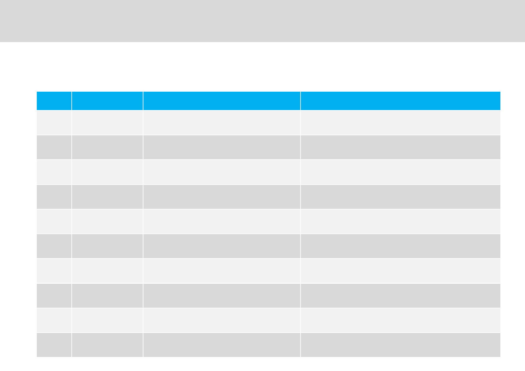
No Item LED Indication Description
'2 "*P=→FFE$F/72
+→FFE$F/72 =P"D'2
'2 "*P6→FFE$F/72
+→FFE$F/72 6P"D'2
, "* "*P6H"*P=→$F/5&&
+→F/$F/5E $+M"0/'&/#1
- "* "*P6H"*P=→F/$F/5E
+→F/$F/72 $2&"+/#"#
"* "*P=→F/$F/72
+→F/$F/72 $"2 "+/#"#Q=
. "* "*P6→F/$F/72
+→F/$F/72 $"2 "+/#"#Q6
4 "* "*P=→F/$F/5E
+→F/$F/72 =$$&"
6 "* "*P6→F/$F/5E
+→F/$F/72 6$$&"
= "* "*P=→F/$F/5E
+→F/$F/5E =/+
"* "*P6→F/$F/5E
+→F/$F/5E 6/+
LED Display
-
Technician’s Installation & Operation Guide
LED Display: operating and alarm status
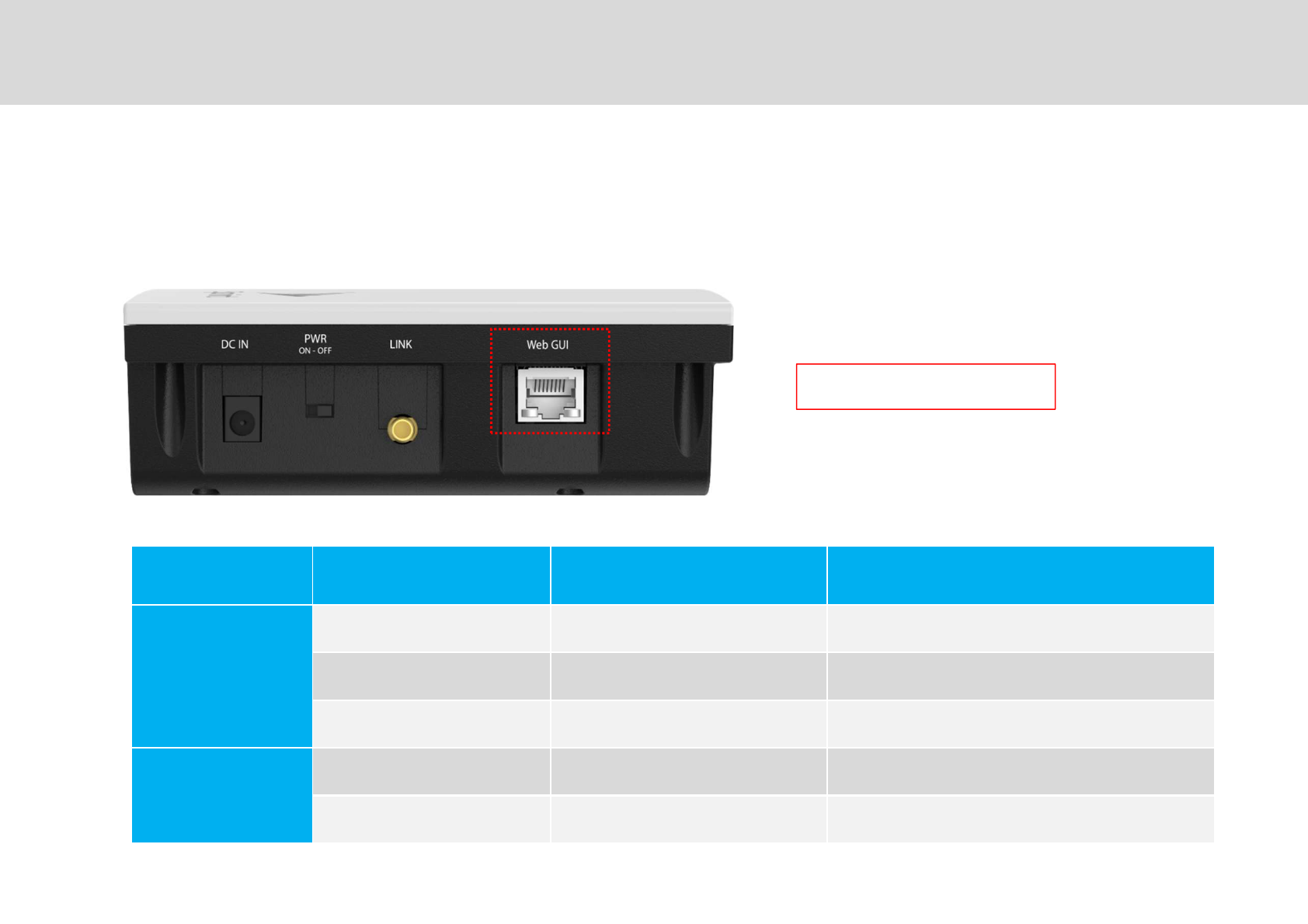
1900MHz Band Block Selection
-
Technician’s Installation & Operation Guide
Frequency Band & Service Instruction Bandwidth
=?9@
/"7 " ?9@?9@?9@
F&"' " ?9@?9@
D ?9@
6?9@
'/? D ?9@
'/?:$F D 4?9@
IP: 192.168.1.1
Service Band Information
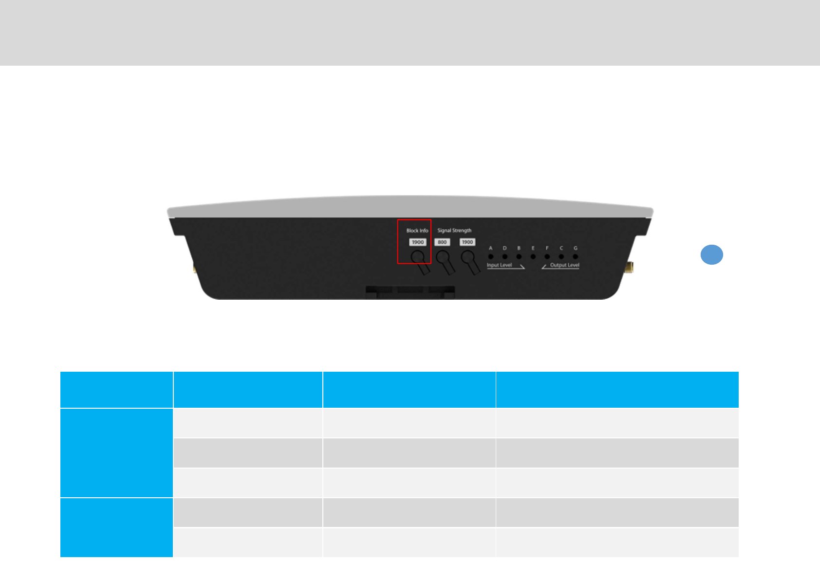
Factory Default Setting
-
Technician’s Installation & Operation Guide
Frequencies Band & Service Instruction Bandwidth
=?9@
/"7 " ?9@?9@?9@
F&"' " ?9@?9@
D ?9@
6?9@
'/? D ?9@
'/?:$F D 4?9@
Block Info
1900
Push ‘Block Info’ button for 10 seconds to return to ‘Factory Default Settings’.
None of the bands will be preset.
The installer should select the necessary blocks for 800MHz and 1900MHz using WebGUI.
R$F/+ " ,"*""G
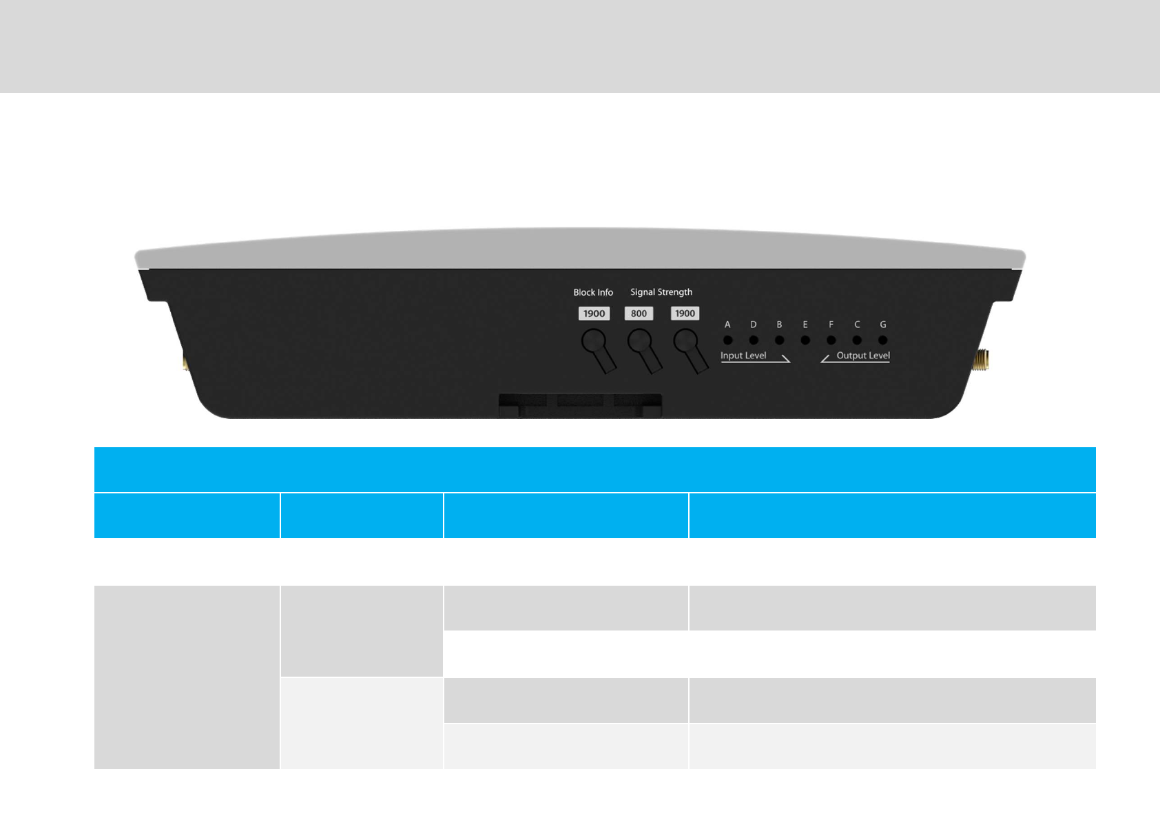
LED Indicator
-,
Technician’s Installation & Operation Guide
Band Block Information and Signal Strength
LED Display Info
Button Frequency Instruction Description
72 = 7" *" =?9@72 *"
"
6
'2 6?9@"$01
'2 6?9@5+$
=
'2 =?9@"$01
'2 =?9@5+$
R$F/+ " ,"*""G
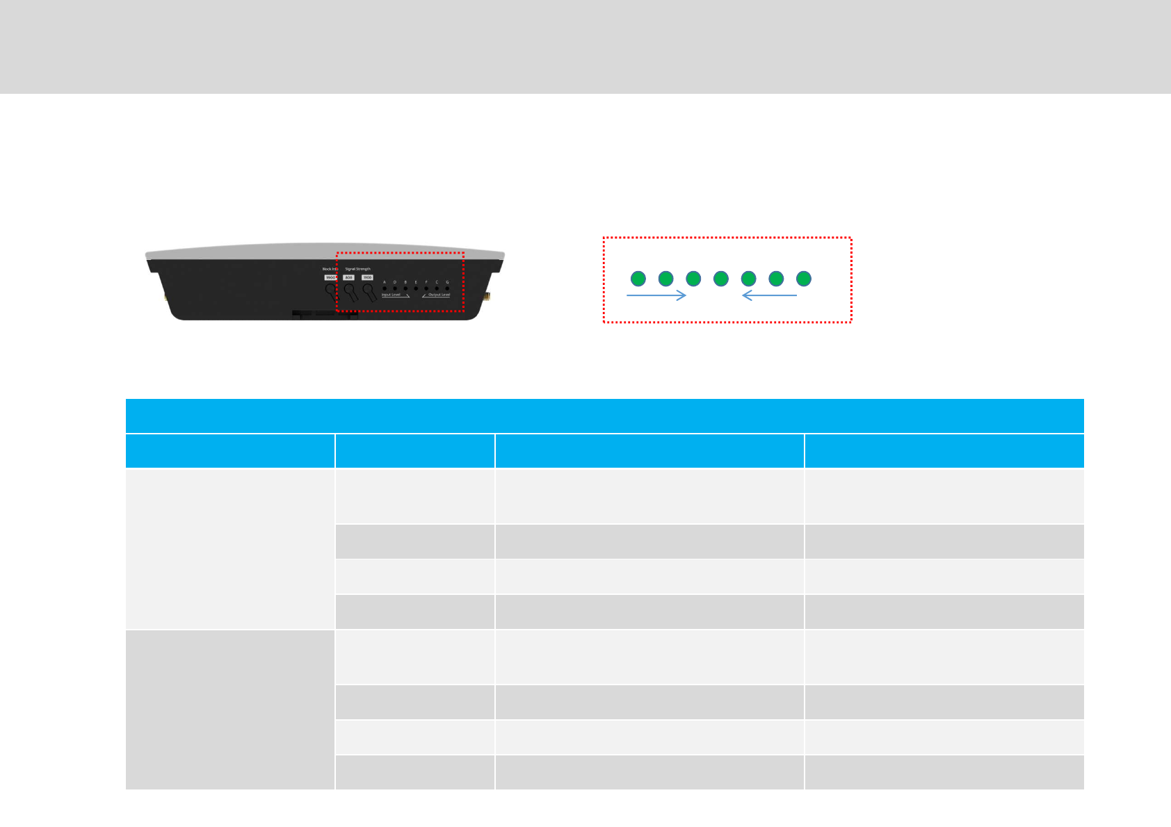
/ 7 F & '
$ 5$
LED Indicator
--
Technician’s Installation & Operation Guide
Signal Strength Indicator
GS Teletech, Inc.
LED Level Bar ( A / D / B / E / F / C / G)
Items LED Values Status
"$
021 D67*+ 7"
/ D6-7*SD47* " "G
/7F D4-7*SD47*
/7F&' D.=7*" FI
5+
021 D7*+ 7"
' D=7*S7* " "G
'&F :7*S:7*
'&F7/ :.7*S:7* FI
R$F/+ " ,"*""G

?"" """++
""""G+"D#"*G+"
"I"***" # ""*"G
"G"J%A
WebGUI
-
Technician’s Installation & Operation Guide
GS Teletech, Inc.
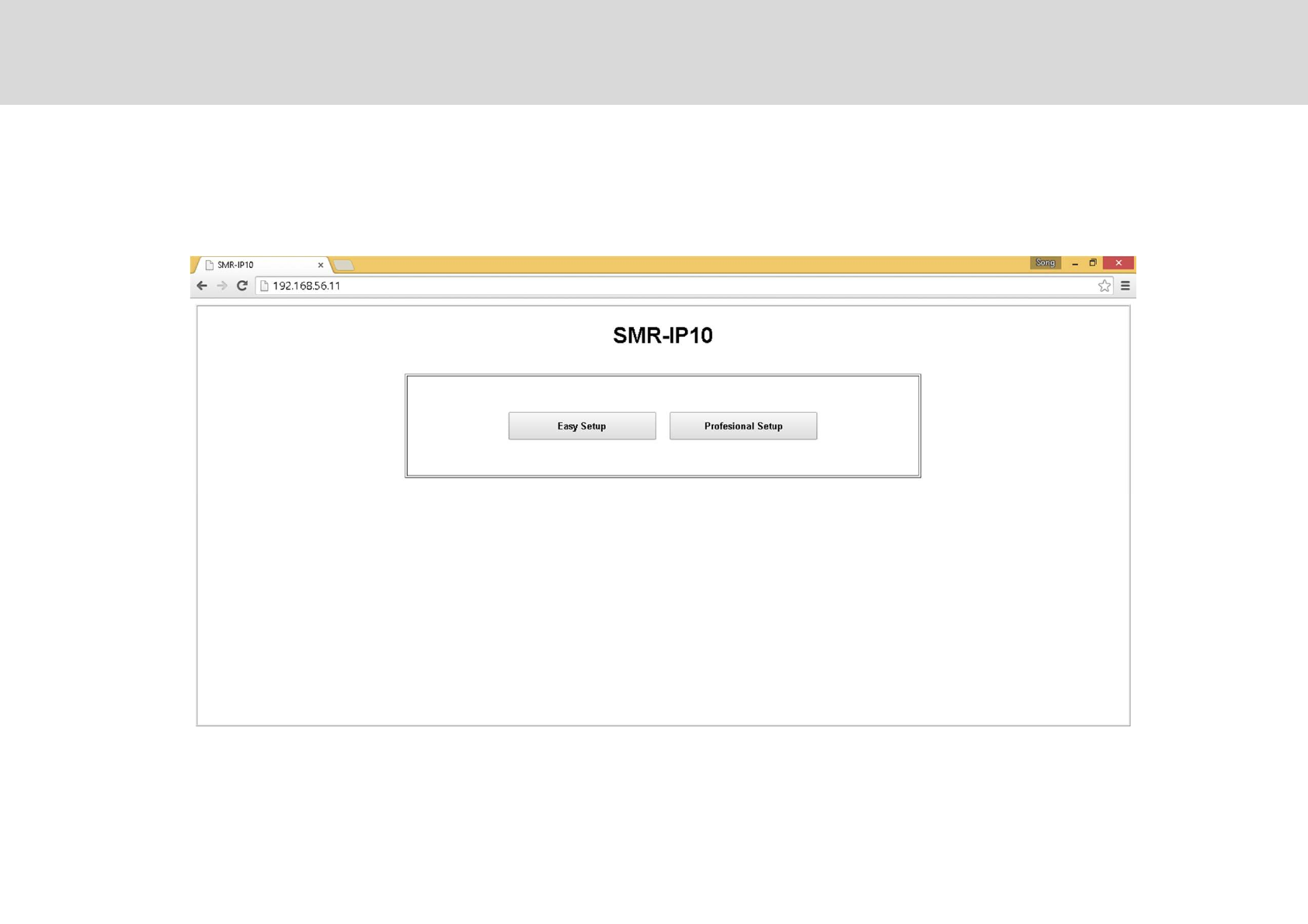
-.
Technician’s Installation & Operation Guide
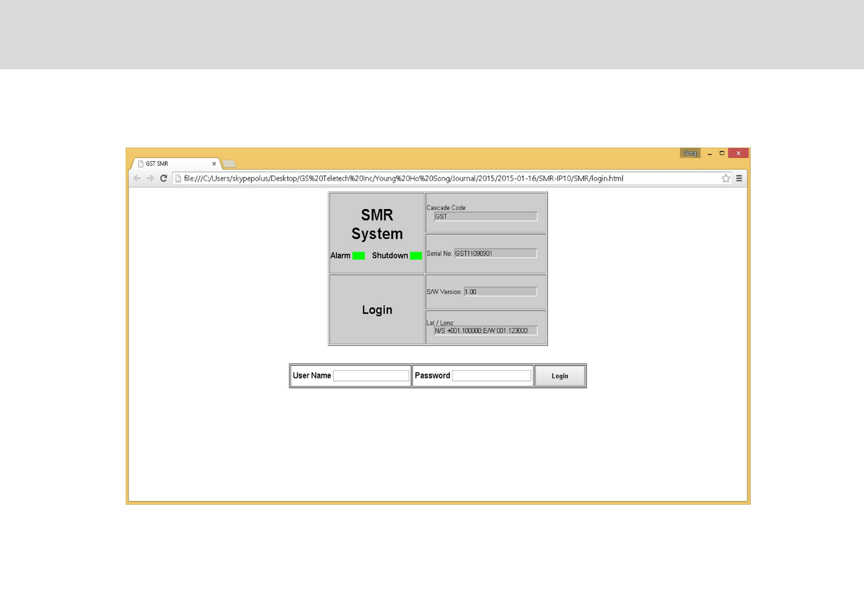
IP Address: 192.168.1.1
Log In
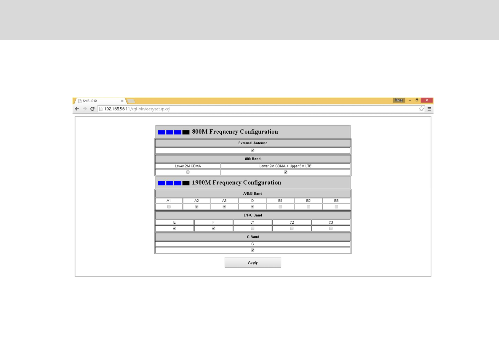
Easy Setup
-4
Technician’s Installation & Operation Guide
Professional Setup
-6
Technician’s Installation & Operation Guide
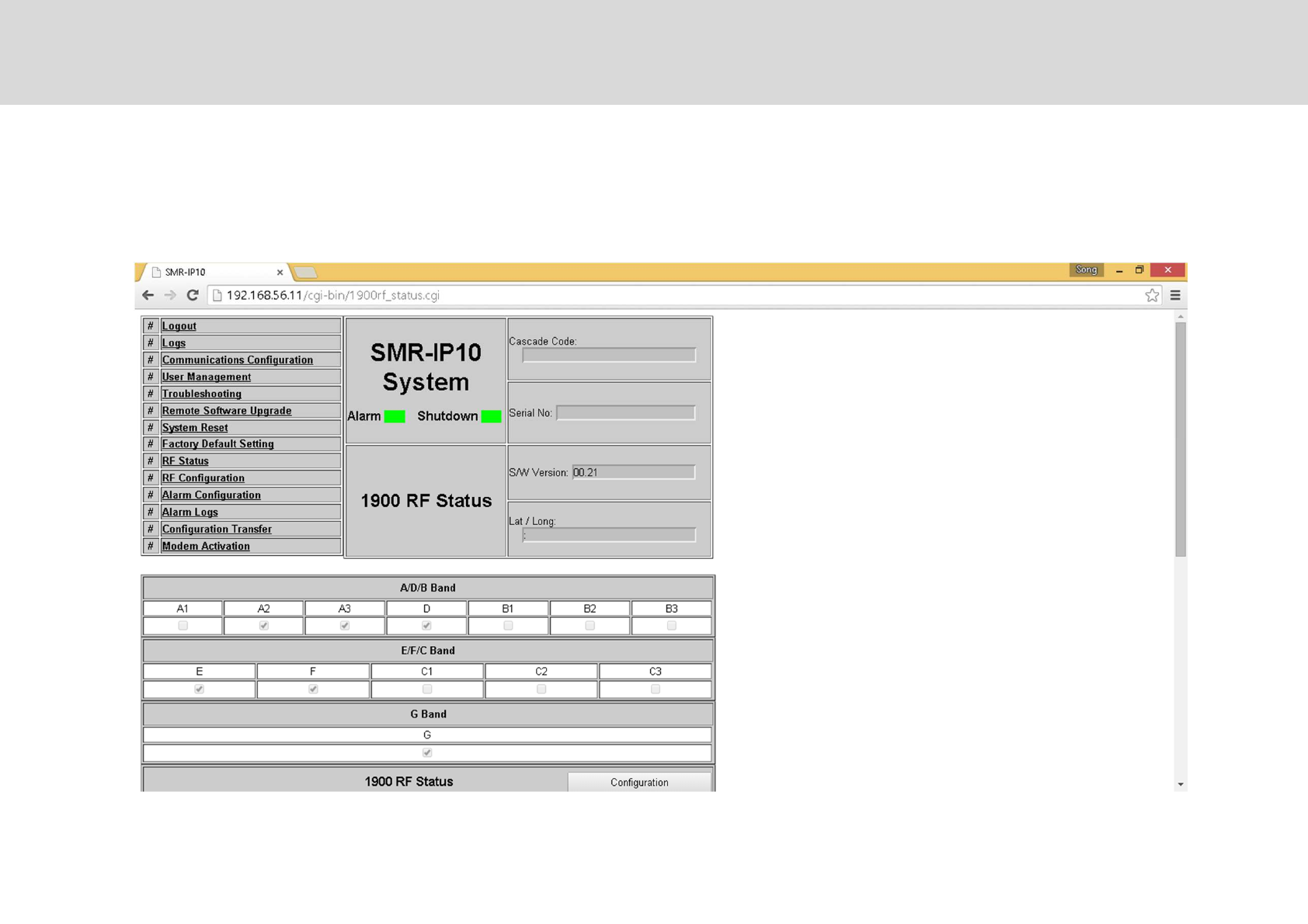
T"2" &"""
RF Status: 1900MHz band.
-=
Technician’s Installation & Operation Guide
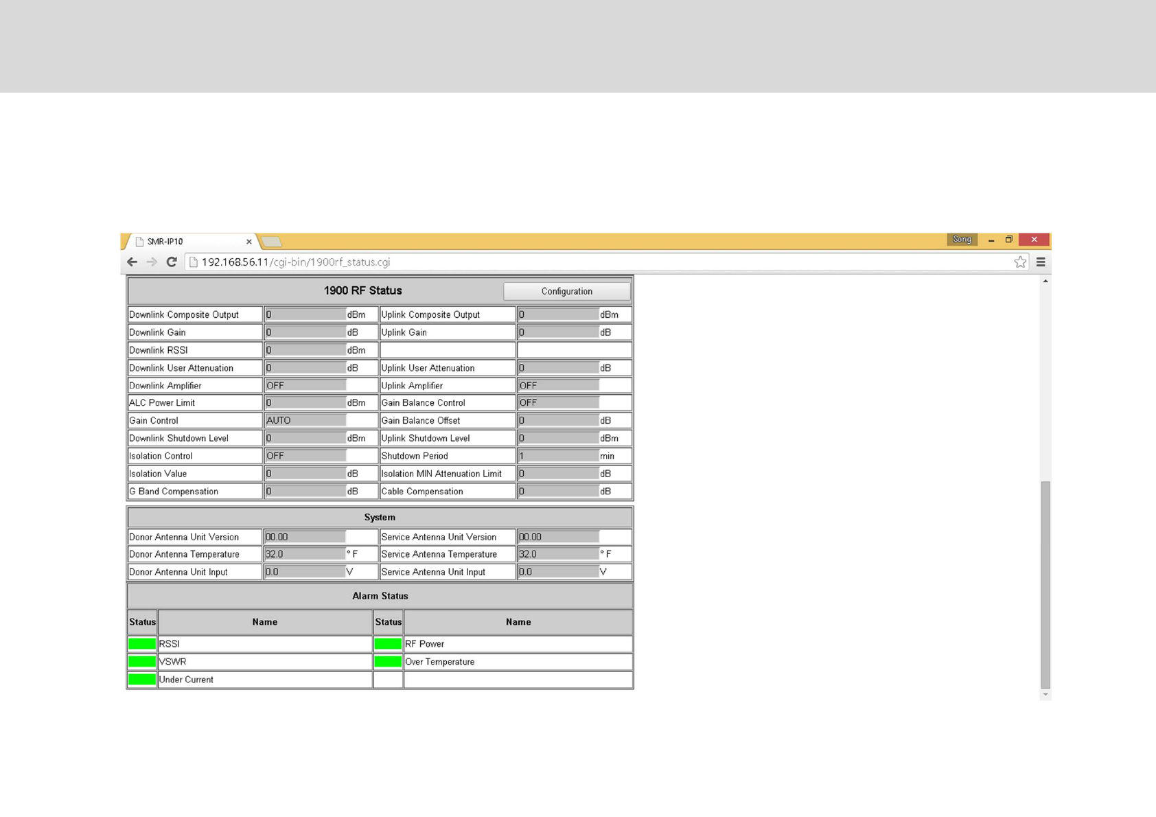
T"2" &"""
Technician’s Installation & Operation Guide
RF Status: 1900MHz band.
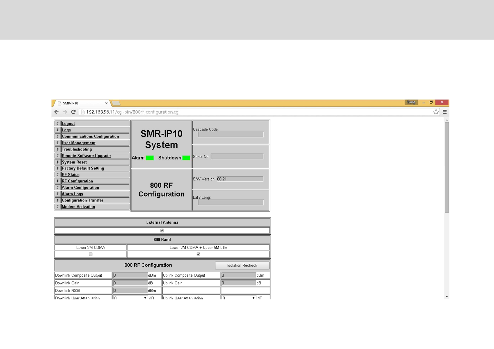
RF Configuration
&""*"& ""
Technician’s Installation & Operation Guide
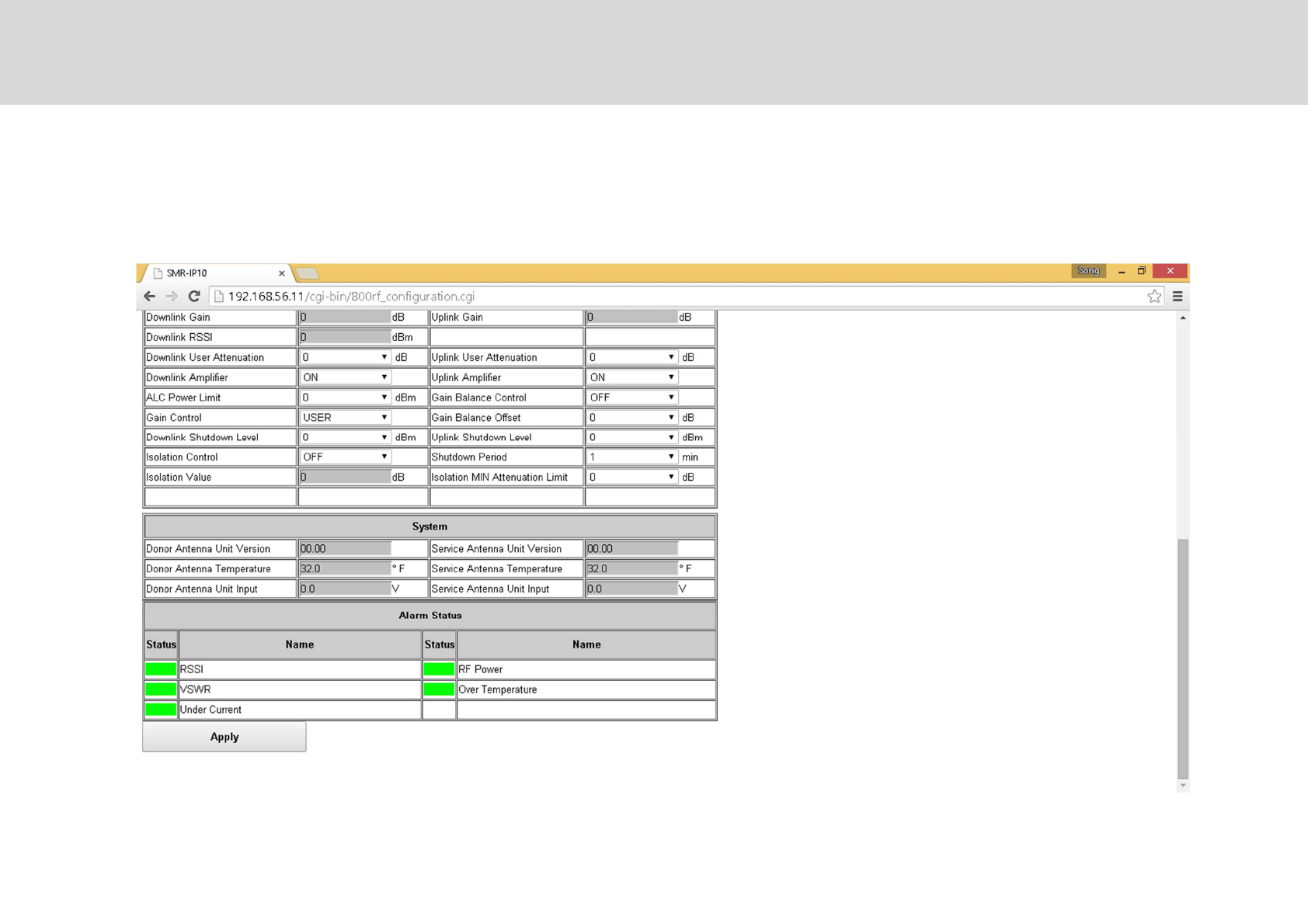
RF Configuration
Technician’s Installation & Operation Guide
&""*"& ""
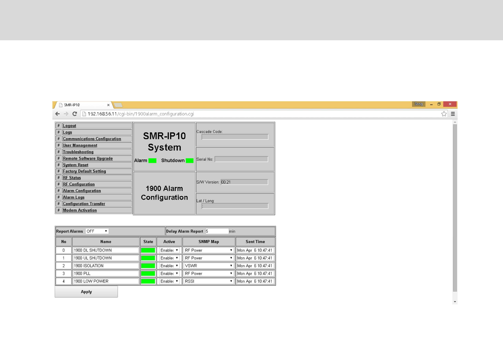
"*"E?*"" "*' ""
Alarm Configuration
,
Technician’s Installation & Operation Guide
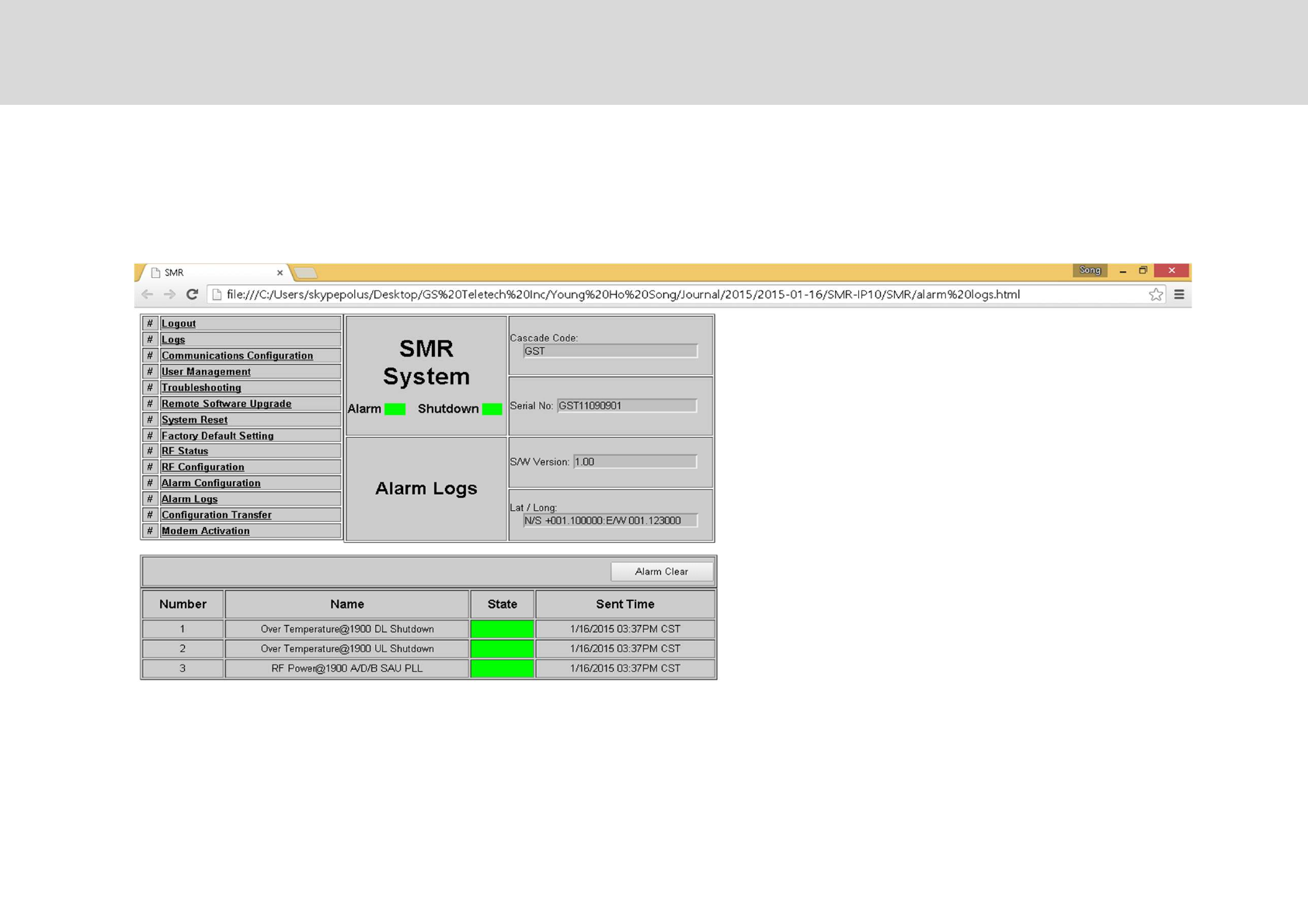
""*""+G2G*""*
Alarm Logs
-
Technician’s Installation & Operation Guide
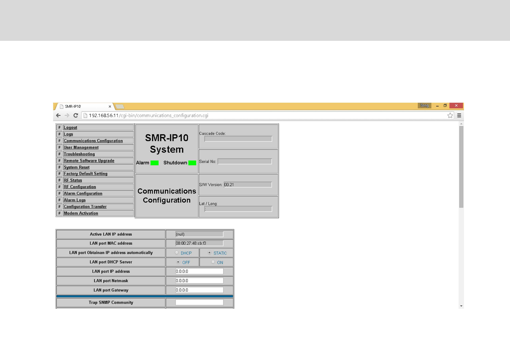
T" ""*%*"'**"' ""
Communication Configuration
Technician’s Installation & Operation Guide
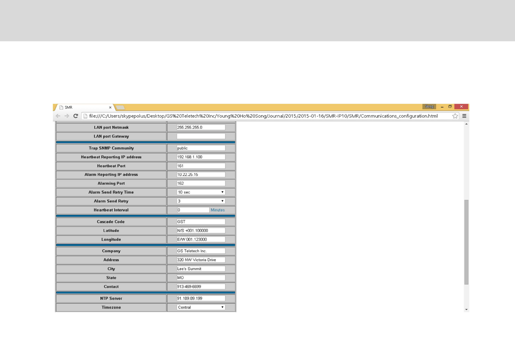
T" ""*%*"'**"' ""
Communication Configuration
.
Technician’s Installation & Operation Guide
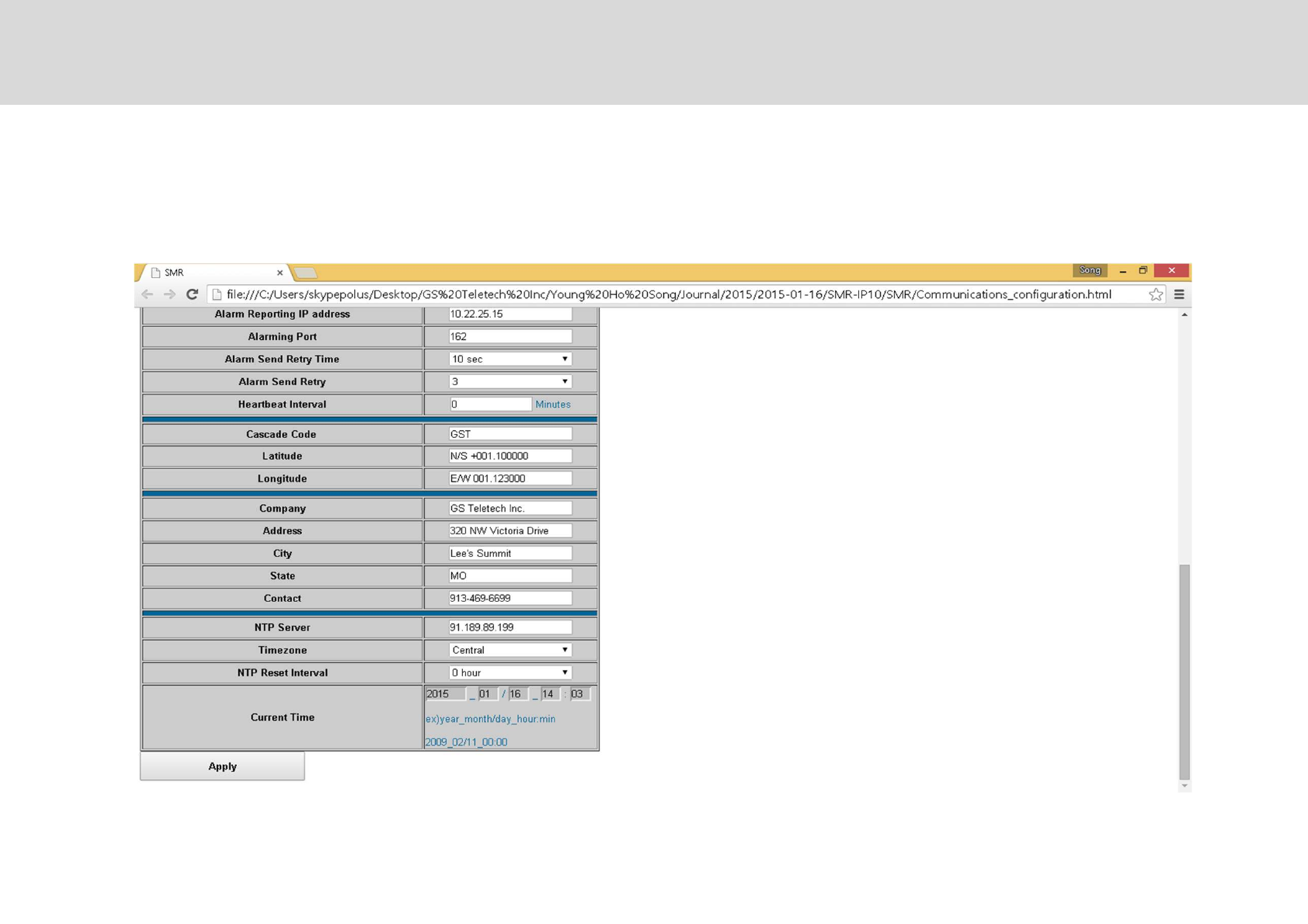
T" ""*%*"'**"' ""
Communication Configuration
4
Technician’s Installation & Operation Guide
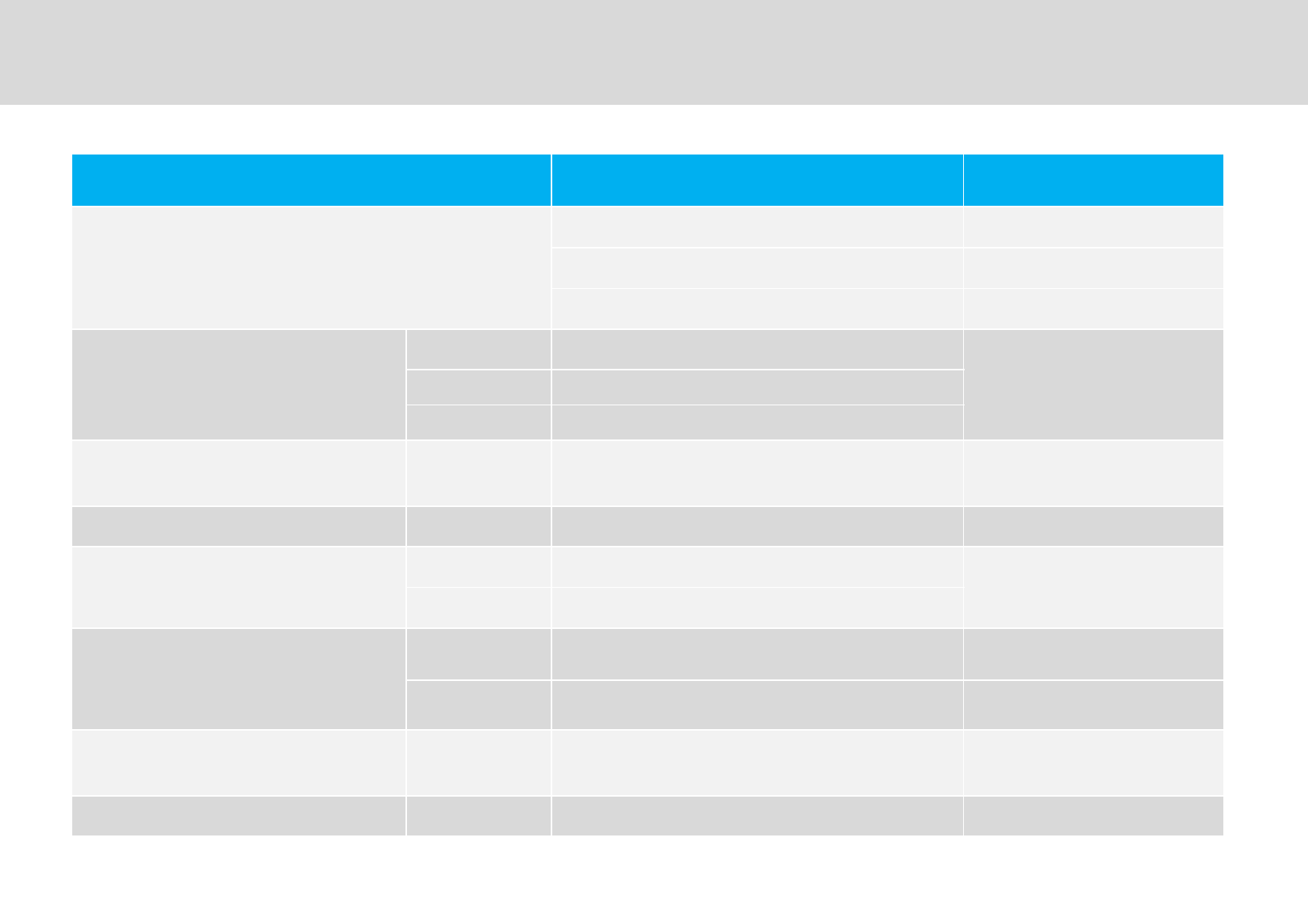
Parameter Specifications Remark
&)G"0/$%#$1
=,S=.?9@%6S66?9@ %/%772
=.S==?9@%66S=?9@ F%&%'72
==S==?9@H=S=?9@ 72
7"+
%/%772 ?9@
%/%7:F%&%':
00,1D"1
F%&%'72 ?9@
72 ?9@
" /$H #$ ,S47±7 'G"*
"(-7
"&" /$H #$ U±7 GD"
'*5+
0F(F ""+1
/$ :7*%"
I%FM/5H$F
#$ :7*%"
'*5+
0F(F ""
+1
/$ :7*%" '""(V7
#$ :47*%" /"(V47
+$ /$%#$ :7*±+7 *""G+
"*
G*/"G /$%#$ U4
Technical Specifications : 1900MHz band
6
Technician’s Installation & Operation Guide
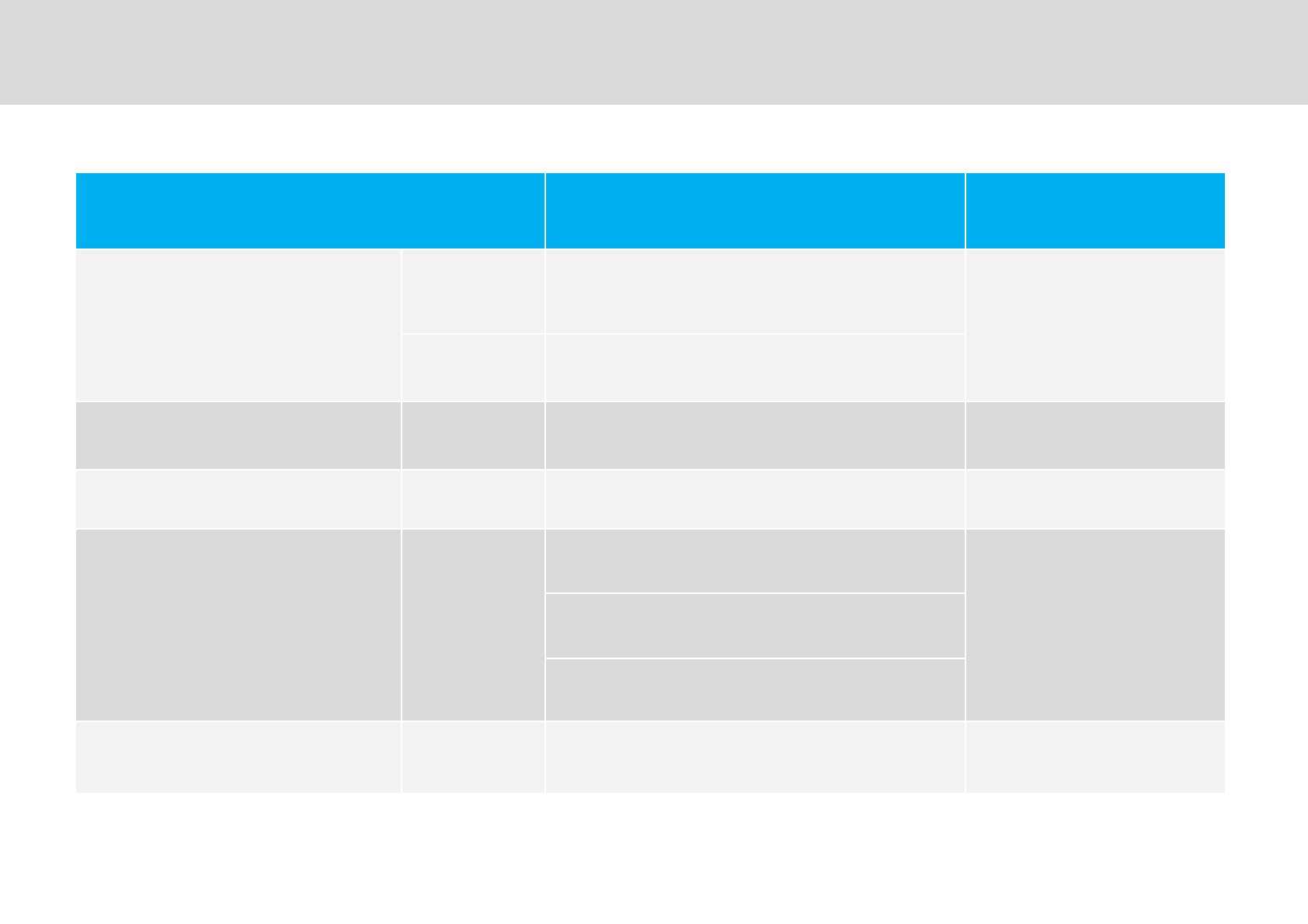
Parameter Specifications Remark
FM?0FM?"1
0A" *3"G&"1
$F /+2(W6K#2(WK
$FHI%FM/5
I%FM/5 X=
%5MA /$%#$ W(
D /$%#$ X7 Q&01±?9@
5D D"
F* /$%#$
X-7Q&±6629@
?&''-4'&
"%%-
X7Q&±=6?9@
WD,7*Q&±?9@07AY?9@1
E& #$ U47 ?"I"
Technical Specifications : 1900MHz band
=
Technician’s Installation & Operation Guide
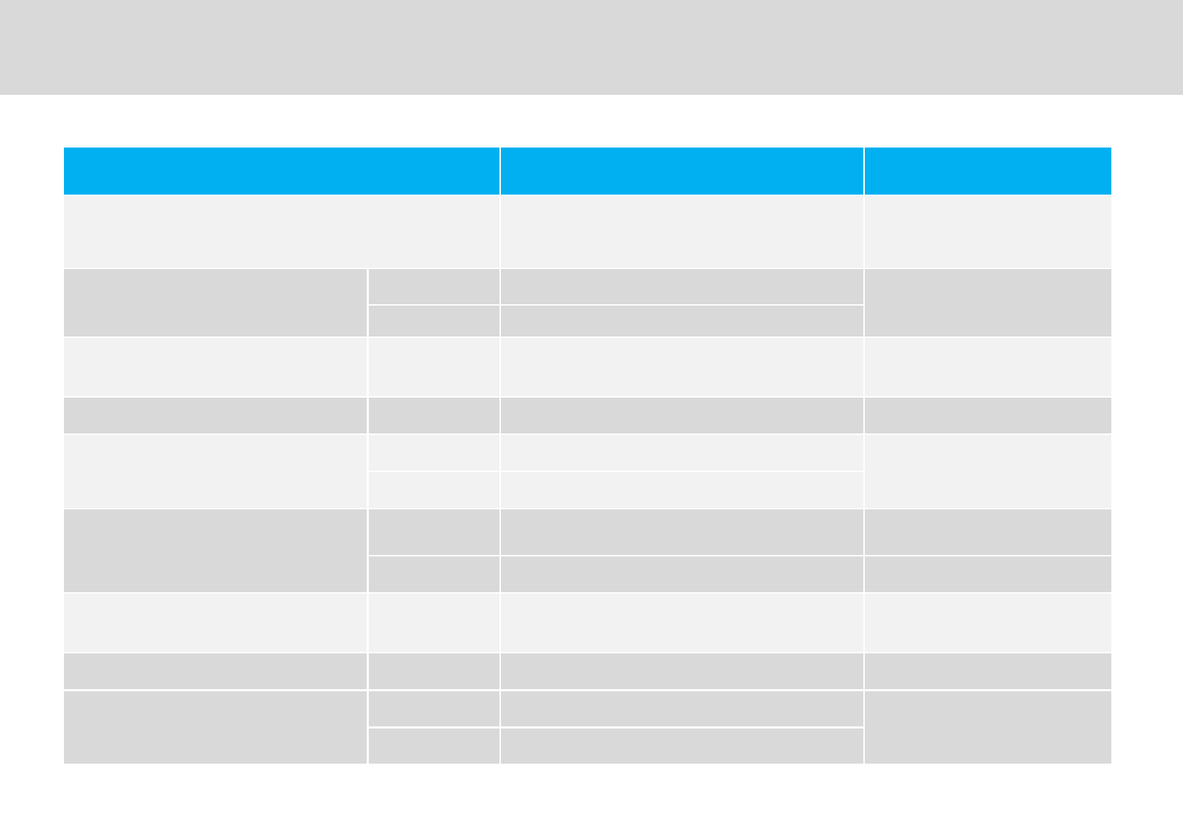
Parameter Specifications Remark
&)G"0/$%#$1 6.S6.-?9@%64S6=?9@
6.-S6.=?9@%6=S6-?9@
'/?
$F
7"+ '/? ?9@ '/?H$F04?9@1
$F ?9@
" /$H #$ ,S47±7 'G"*
"(-7
"&" /$H #$ U±7 $FH'/?
'*5+
0F(F ""+1
/$ :7*%"
'/?H$F
#$ :7*%"
'*5+
0F(F ""
+1
/$ :7*%" '""(V7
#$ :7*%" /"(V7
+$ /$%#$ :7*±+7 *""G+
"*
G*/"G /$%#$ U4
0A" *3"G&"1
FM?0FM?"1
'/? X= '/?
$F
$F /+2(W6K#2(WK
Technical Specifications : 800MHz band
.
Technician’s Installation & Operation Guide
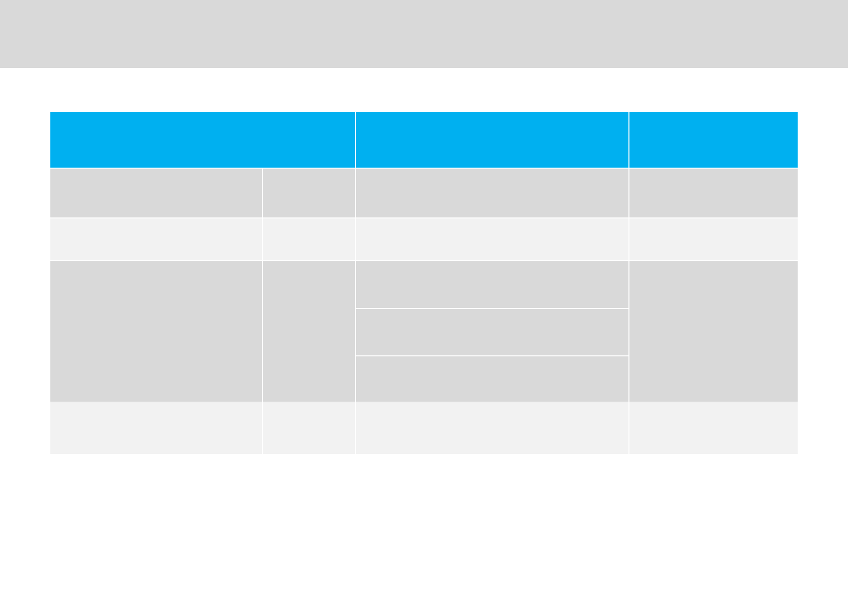
Parameter Specifications Remark
%5MA /$%#$ W(
D /$%#$ X.7 Q&01±?9@
5D D"
F* /$%#$
X-7Q&±6629@
?&''-4'&
"%%-
X7Q&±=6?9@
WD,7*Q&±?9@07AY?9@1
E& #$ U47 ?"I"
Technical Specifications: 800MHz band
.
Technician’s Installation & Operation Guide
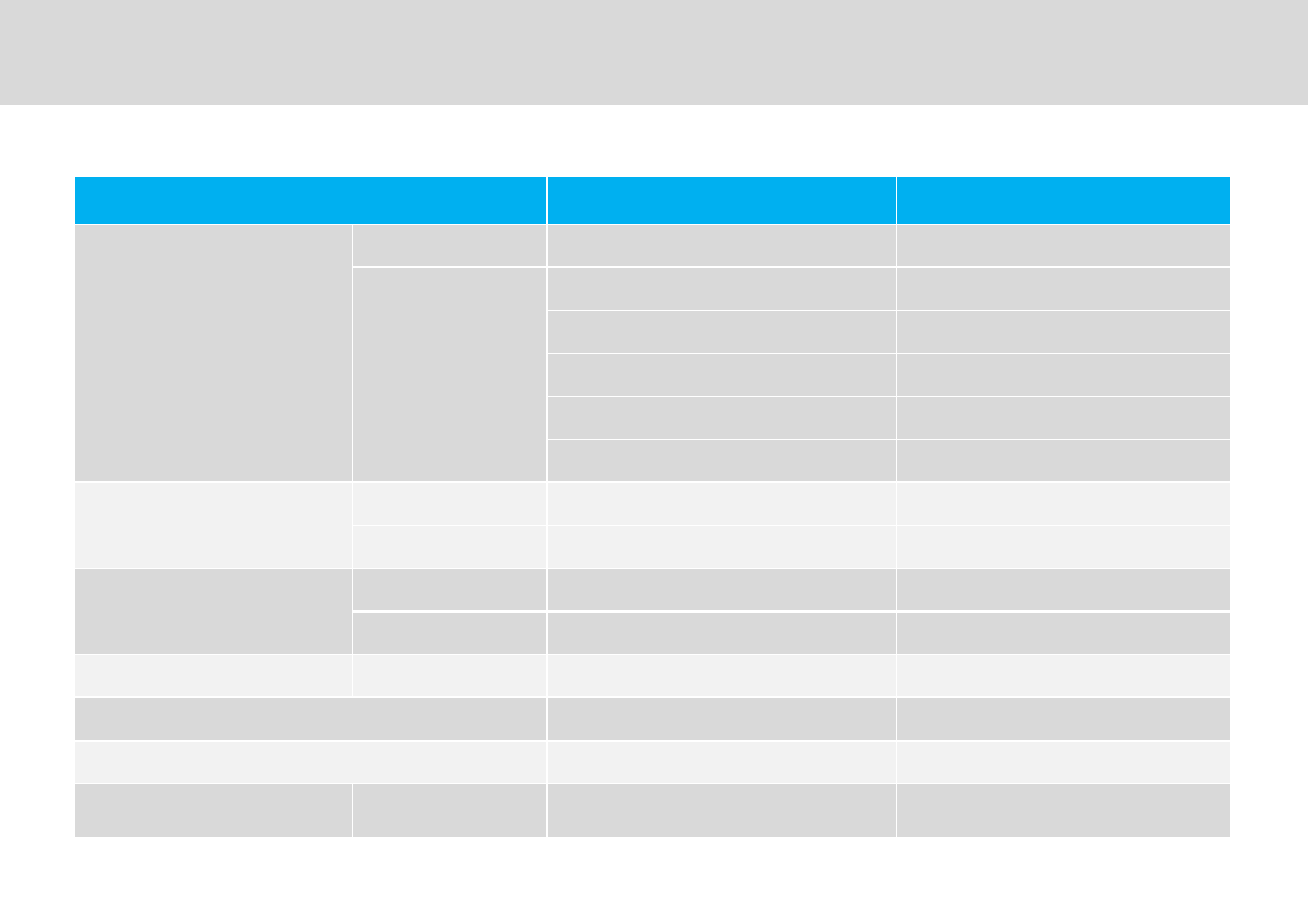
Parameter Specifications Remark
'
*"
/# ?0&1 &$2
#
?0&1 &$2
?0&1 '"FI"
>D- A#
/'>"2 '%/'"
+ +5E%5&&
ZF09IAI/1
/# ..=I4.4I.4BC 4I=I.6B**C
# =.-I=IBC -II.B**C
A
/# W,BC .B!C
# W,BC .B!C
# " $"# AD#
5"*" :-°&S:°&0D°'S:°'1
9*G KS=K
+'* /# H# W,.A FI"'%/'"=M%,
Mechanical Specifications
.
Technician’s Installation & Operation Guide
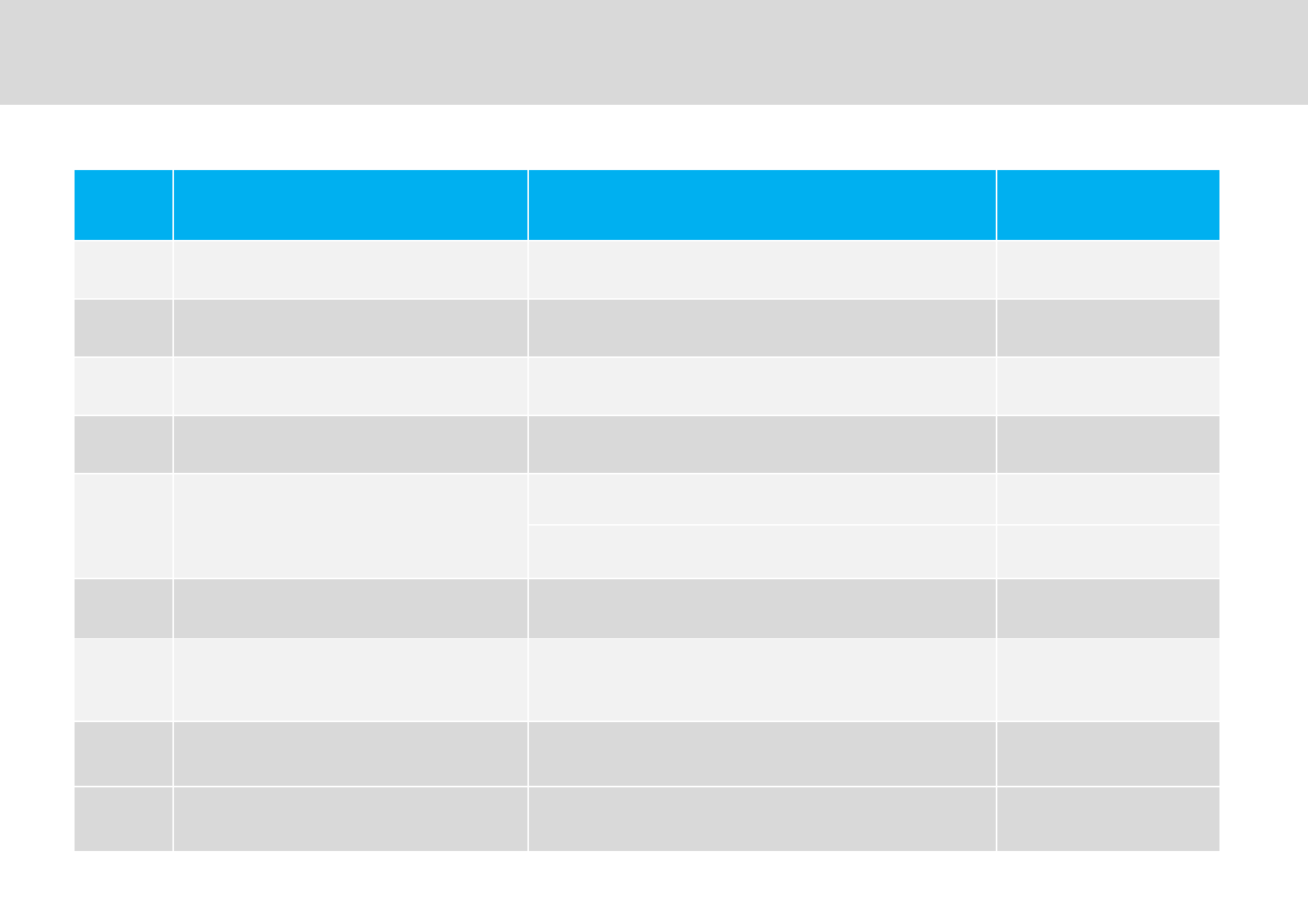
.,
Technician’s Installation & Operation Guide
Link Cable Specifications
No Parameter Specifications Remark
1*" [0E*"1
2&)G ?9@S,?9@
3MA (
4$ D,7SD7
5'""
''"(,*[0?"I1
5'"(*[0?"I1
6"" ?[0?1
7/A"
M" 4M*
8/'" -S\
9$2/" .- 0*1
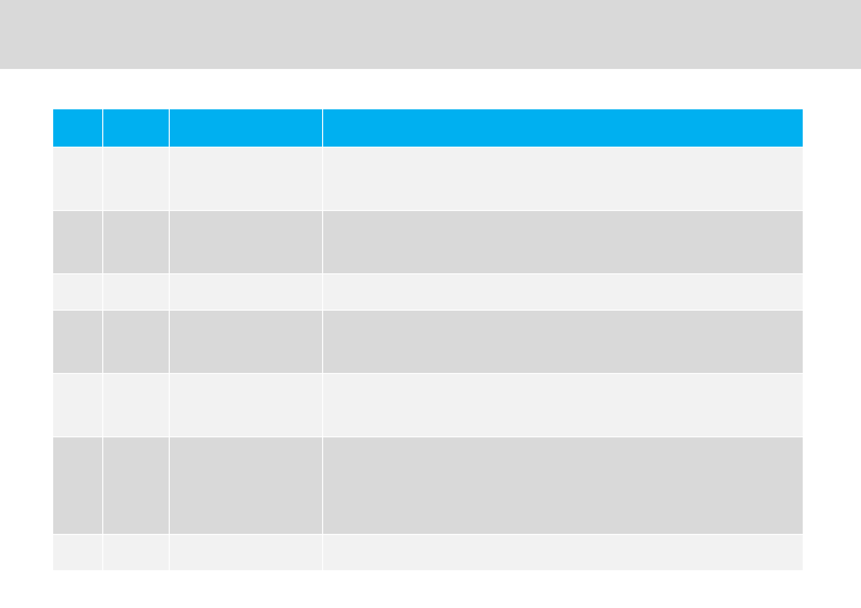
Troubleshooting
.-
Technician’s Installation & Operation Guide
No Item Description Troubleshooting
"* $+"
'2 N/$J"A#
"*"D67*0**"1
" */#"
" *7
"* "
'"G"2 "+/#"#
'" /# *" +/#"#
""U":7
, "* "D'2 " D2"+"+/#D"""#
D""
- "* $+M"
/# " * " :M/' /' +
'2 $2 '" /# " #
'2 /' " /' O"2 '%/' "" G ?D* 0 1
" " =M/'±M
"* $2&"
'2 $2"/#"#
'2"/'"
E*"/'"(-\S\
. "* +
'2" /#
""D7*0A#1/#J
""(D7*"
'2$'"A#"$'
4 "* $$&" ""?D++

Phone Write Product Information and
Technical Assistance
Specifications and features of this installation guide are subject to change without notice or obligation.
GST Technical Support
&(D6..D=#
(=,D-.=D..==
,EAM"/
$J**?5.-6.#
+++*
Q*
Technician’s Installation & Operation Guide