GS Instech SMT-A33 CDMA In-Building RF Repeater User Manual
GS Instruments Co., Ltd. CDMA In-Building RF Repeater
UserManual.wiki
>
GS Instech
>
SMT A33 User Manual
User Manual
Navigation menu
Upload a User Manual
Namespaces
Wiki Guide
HTML
PDF
Info
Views
User Manual
Discussion / Help
Navigation
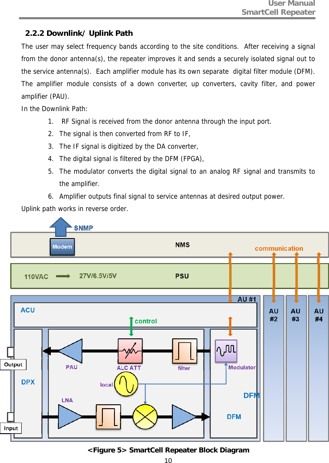
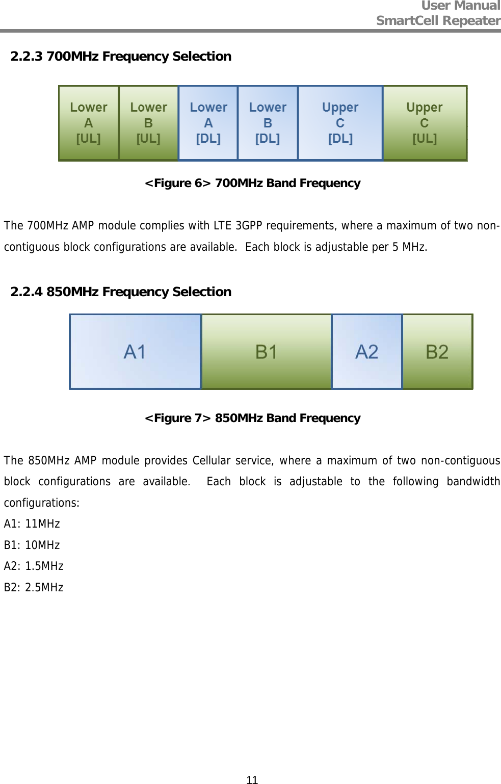
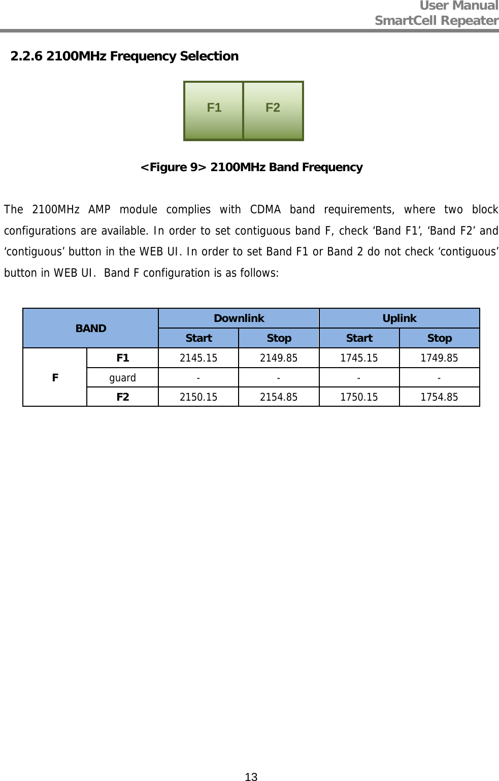
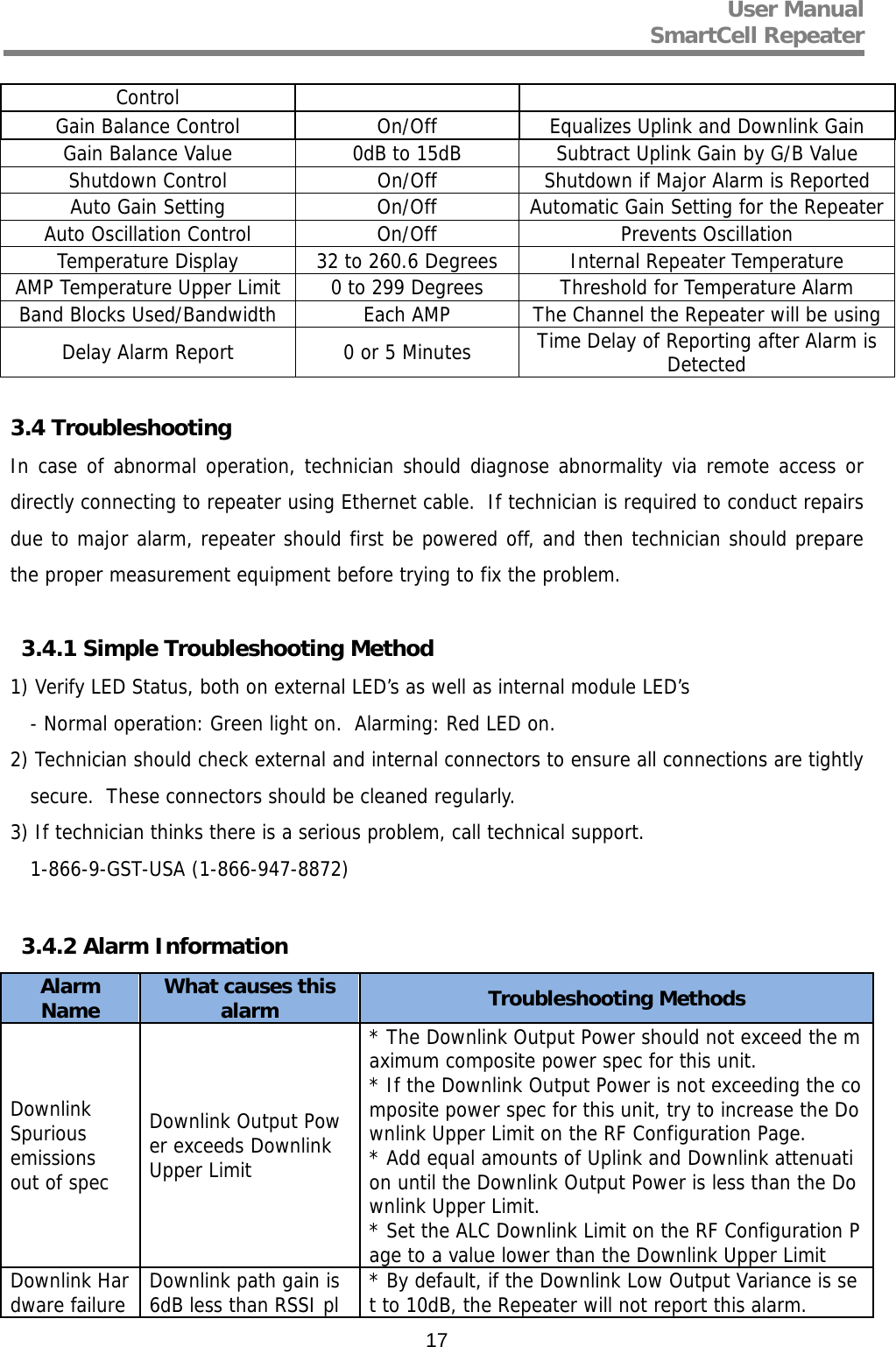
![User Manual SmartCell Repeater 122.2.5 1900MHz Frequency Selection <Figure 8> 1900MHz Band Frequency The 1900MHz AMP module complies with PCS Band blocks, where a maximum of three non-contiguous filtering configurations are available. Each sub block is adjustable per 1.25MHz bandwidth steps up to 20MHz. The Following table shows user selectable channel numbers. BAND DL CENTER [MHz] CHANNEL BAND DL CENTER [MHz] CHANNEL A A1 1931.25 25 guard 1965 700 1932.5 50 E 1966.25 725 1933.75 75 1967.5 750 guard 1935 100 1968.75 775 A2 1936.25 125 guard 1970 800 1937.5 150 F 1971.25 825 1938.75 175 1972.5 850 guard 1940 200 1973.75 875 A3 1941.25 225 guard 1975 900 1942.5 250 C C1 1976.25 925 1943.75 275 1977.5 950 guard 1945 300 1978.75 975 D 1946.25 325 guard 1980 1000 1947.5 350 C2 1981.25 1025 1948.75 375 1982.5 1050 guard 1950 400 1983.75 1075 B B1 1951.25 425 guard 1985 1100 1952.5 450 C3 1986.25 1125 1953.75 475 1987.5 1150 guard 1955 500 1988.75 1175 B2 1956.25 525 G 1992.5 1225 1957.5 550 1958.75 575 1250 guard 1960 600 B3 1961.25 625 1275 1962.5 650 1963.75 675](https://usermanual.wiki/GS-Instech/SMT-A33/User-Guide-1843057-Page-12.png)