GS Instech SMT-I33 In-Building RF Repeater User Manual
GS Instruments Co., Ltd. In-Building RF Repeater
UserManual.wiki
>
GS Instech
>
SMT I33 User Manual
User Manual
Navigation menu
Upload a User Manual
Namespaces
Wiki Guide
HTML
PDF
Info
Views
User Manual
Discussion / Help
Navigation
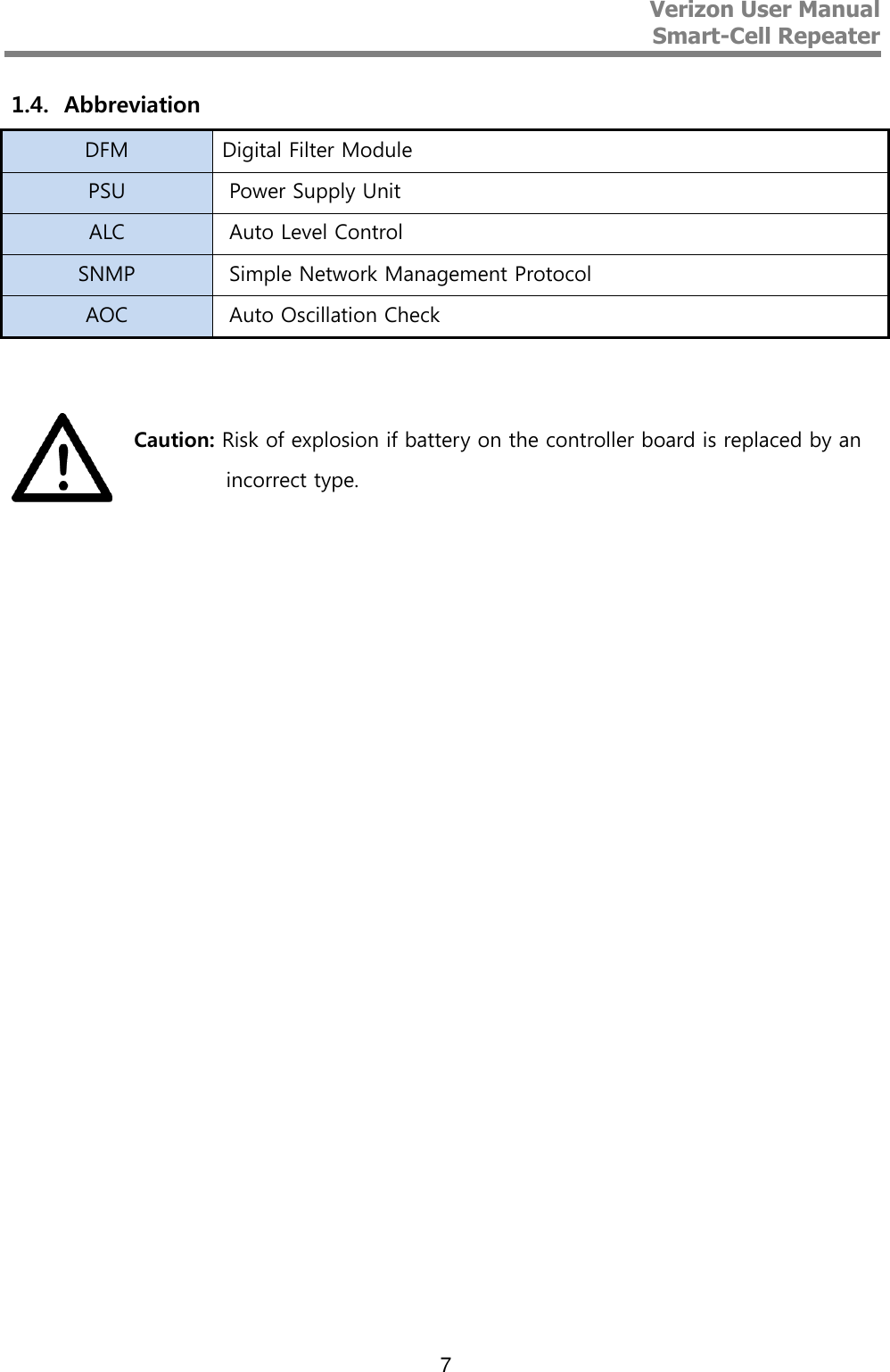
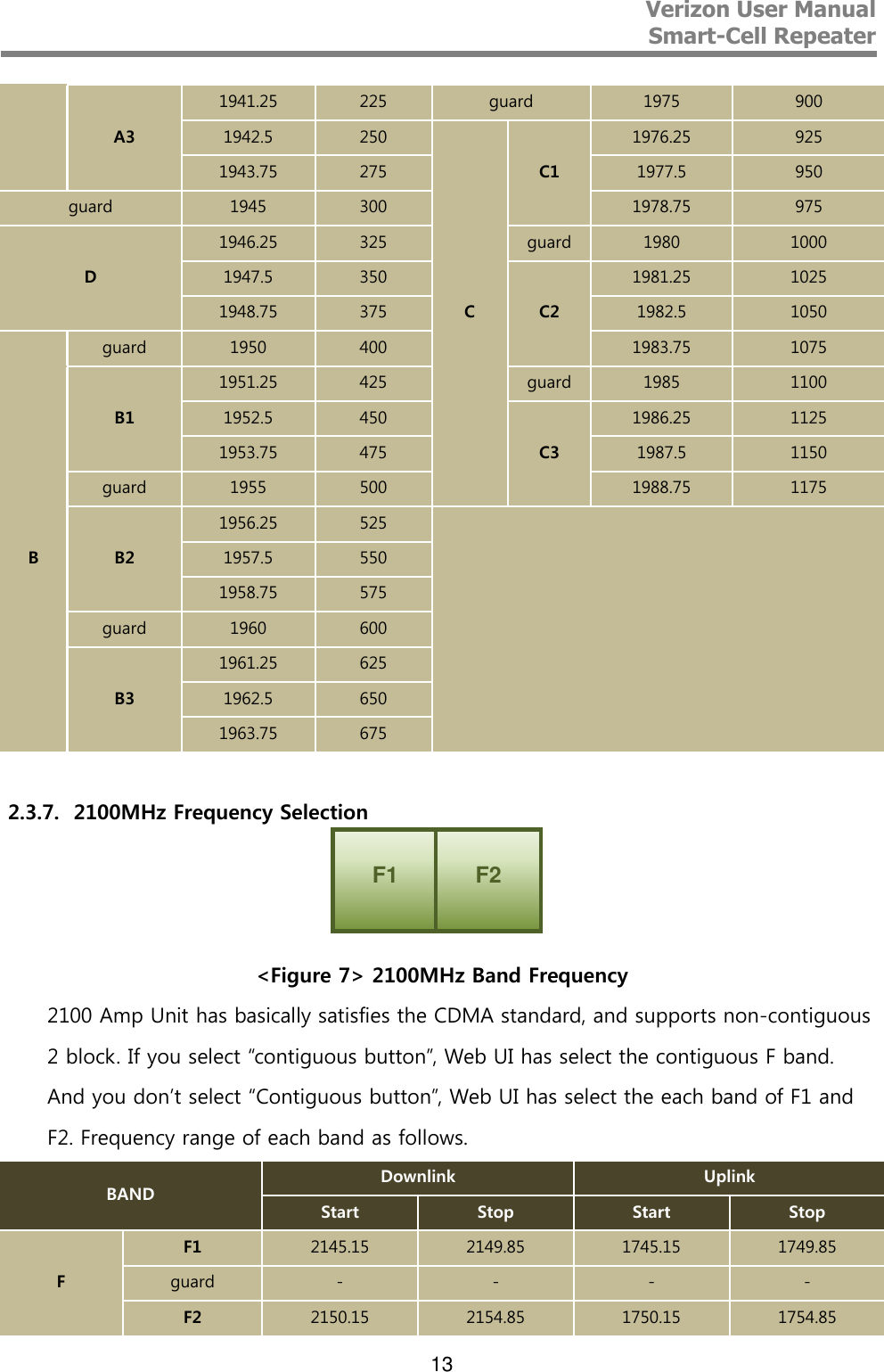
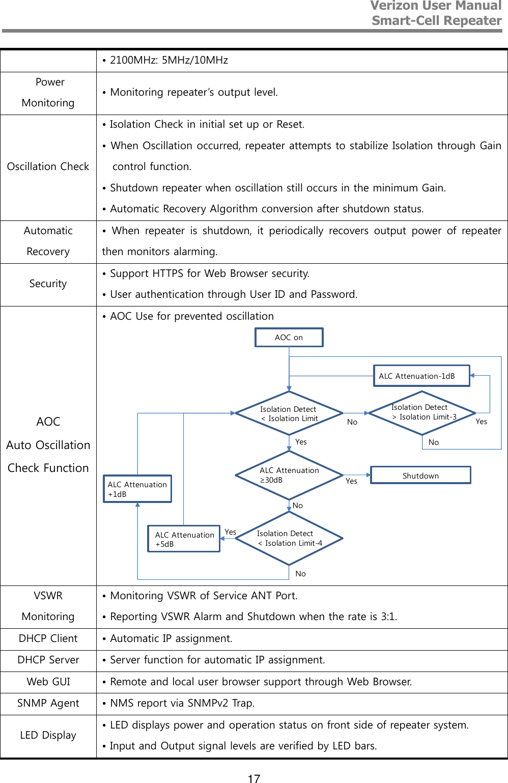
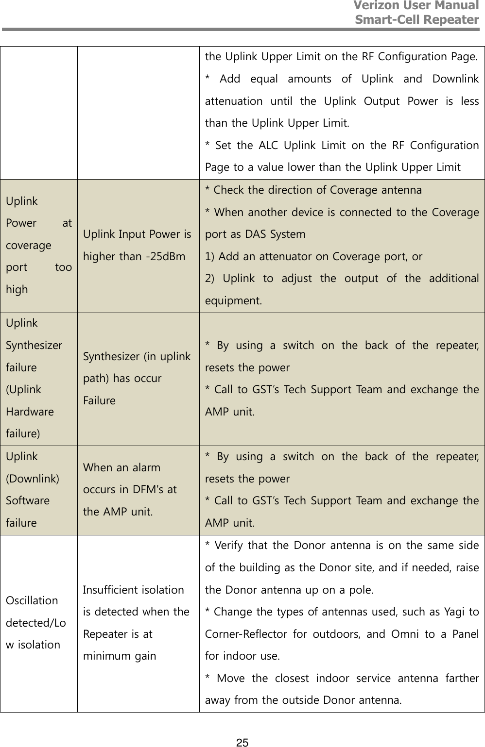
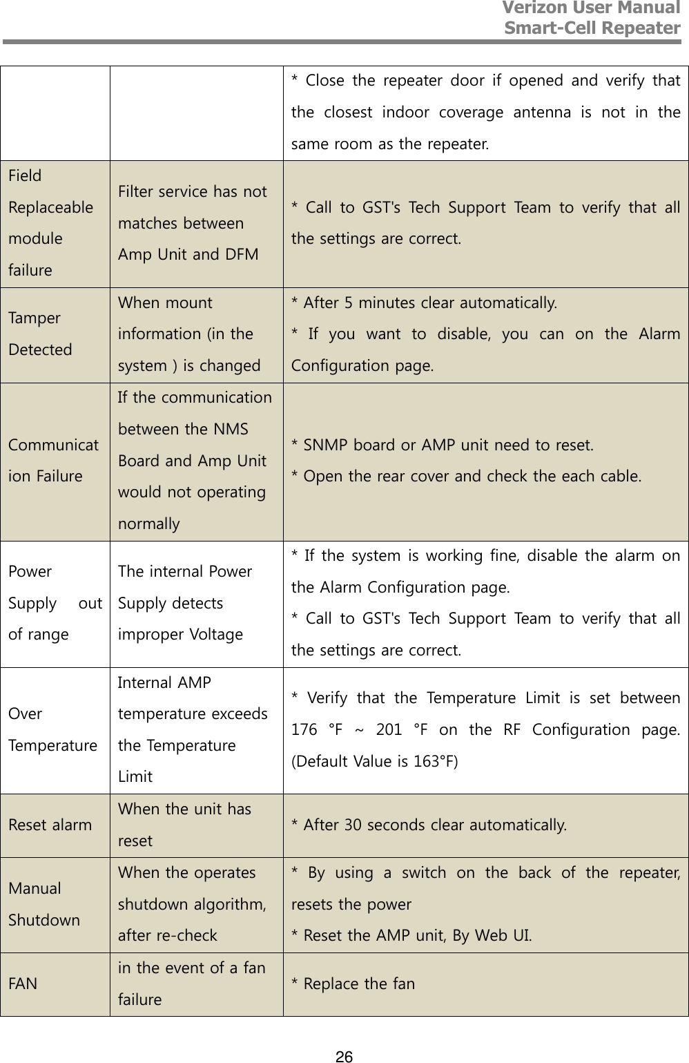
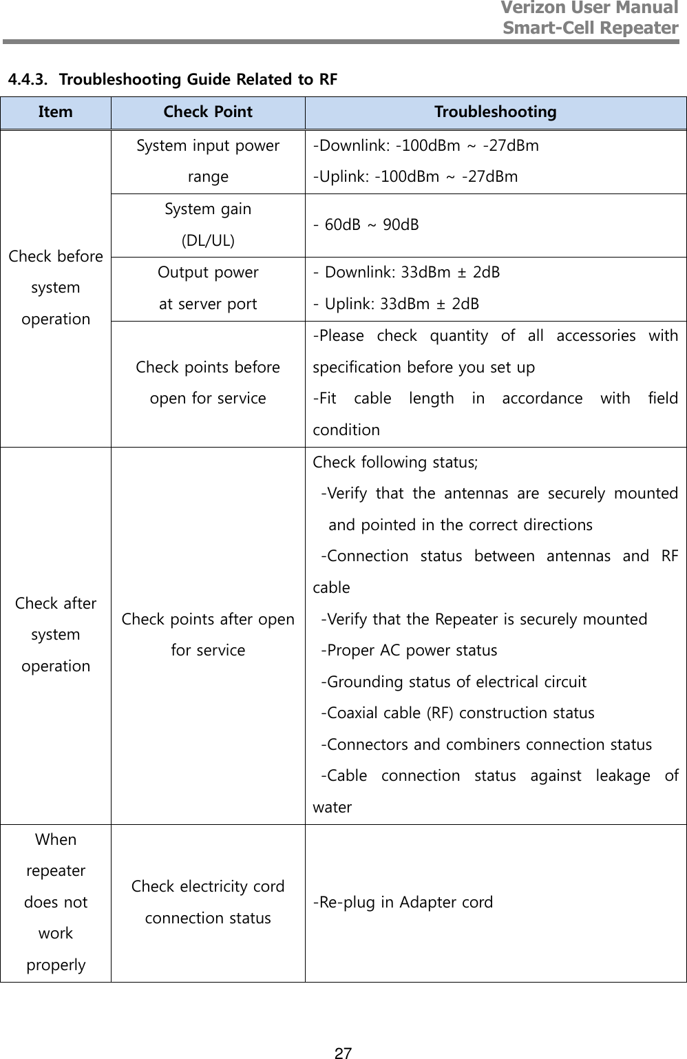
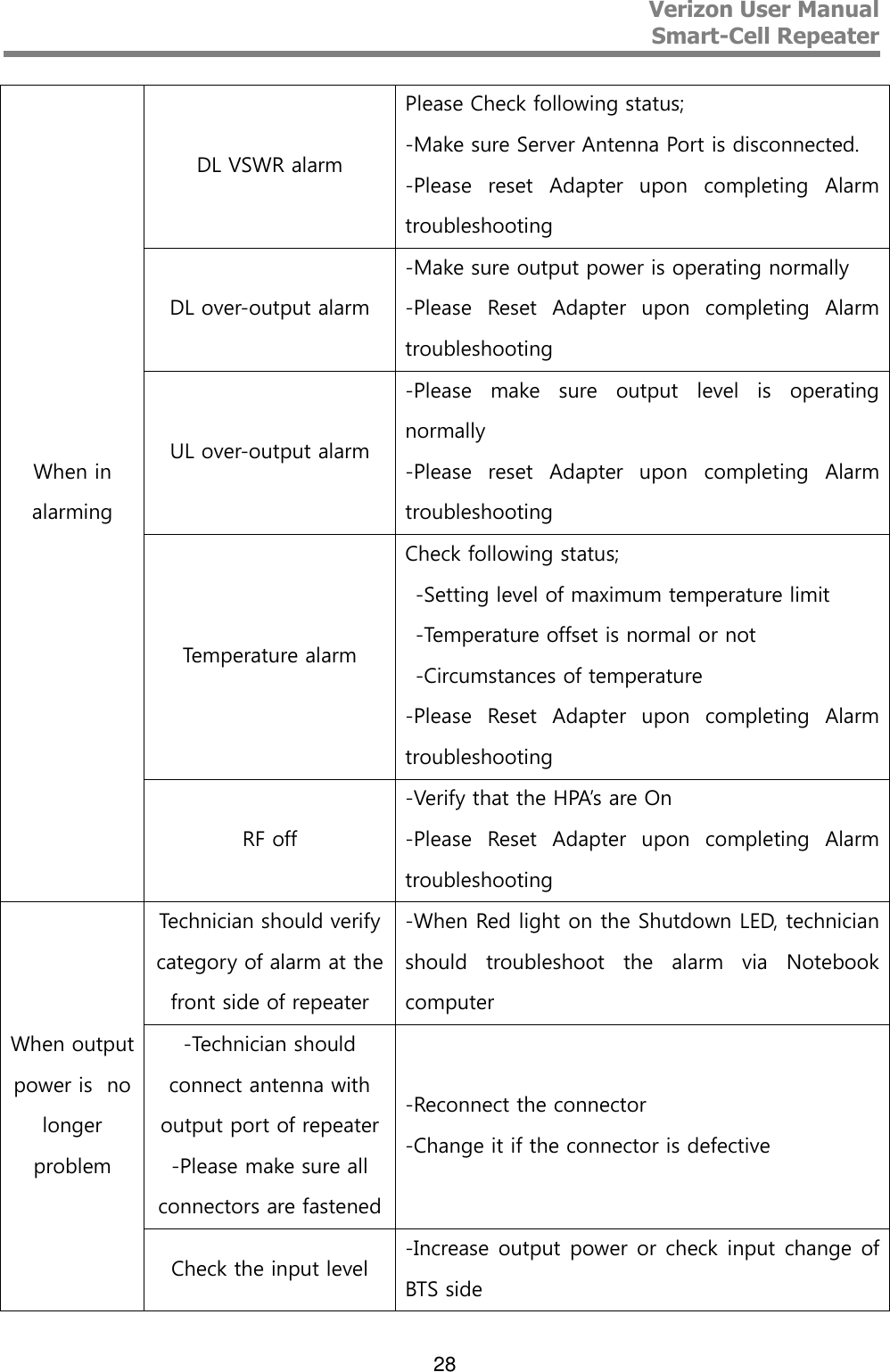
![Verizon User Manual Smart-Cell Repeater 12 On / Off control of the service Block is possible. Each block‘s bandwidth are as follows. (CDMA[UL] – 1.25MHz, LTE[UL] – 4.505MHz, CDMA[DL] – 1.25MHz, LTE[DL] – 4.505MHz) 2.3.5. 850MHz Frequency Selection <Figure 7> Smart-Cell Repeater 850 Block Diagram 850MHz Cellular service provides by default, and supports up to two non-contiguous blocks. Each block‘s bandwidth are as follows, and it is possible to choose any combination of any band. (A1 - 11MHz, B1 - 10MHz, A2 - 1.5MHz, B2 - 2.5MHz.) 2.3.6. 1900MHz Frequency Selection <Figure 8> 1900MHz Band Frequency 1900MHz AMP Unit is basically complied with PCS Band block, where maximum three non-contiguous filtering configurations are available. Each sub block is adjustable per 1.25MHz bandwidth step up to 20MHz. Following table shows user selectable channel numbers. BAND DL CENTER [MHz] CHANNEL BAND DL CENTER [MHz] CHANNEL A A1 1931.25 25 guard 1965 700 1932.5 50 E 1966.25 725 1933.75 75 1967.5 750 guard 1935 100 1968.75 775 A2 1936.25 125 guard 1970 800 1937.5 150 F 1971.25 825 1938.75 175 1972.5 850 guard 1940 200 1973.75 875](https://usermanual.wiki/GS-Instech/SMT-I33/User-Guide-2605305-Page-12.png)