GS Instech SMT-L33 LTE In-Building RF Repeater User Manual
GS Instruments Co., Ltd. LTE In-Building RF Repeater
User Manual
SmartCell Repeater
User Manual
33 dBm
July, 2012
Version 1.0

User Manual
SmartCell Repeater
2
- INDEX -
1. INTRODUCTION ............................................................................................................. 3
1.1 GST SmartCell Repeater Advantages ........................................................................... 5
1.2 Abbreviation ................................................................................................................. 5
2. SYSTEM CONFIGURATION ............................................................................................. 7
2.1 SmartCell Repeater Service Network Configuration .................................................... 7
2.2 System Design and Operation ...................................................................................... 8
2.2.1 System Design ....................................................................................................... 8
2.2.2 Downlink/ Uplink Path ........................................................................................ 10
2.2.3 700MHz Frequency Selection .............................................................................. 11
2.2.4 850MHz Frequency Selection .............................................................................. 11
2.2.5 1900MHz Frequency Selection ............................................................................ 12
2.2.6 2100MHz Frequency Selection ............................................................................ 13
3. SETUP ........................................................................................................................... 14
3.1 Equipment Needed for Repeater Setup ...................................................................... 14
3.1.1 Check points before turning on the Repeater ...................................................... 14
3.1.2 Ready for Service ................................................................................................. 15
3.1.3 Signal Strength LED Check .................................................................................. 15
3.2 Setting up the Repeater ............................................................................................. 15
3.2.1 Quick GUI/Configuration ..................................................................................... 16
3.2.2 Quick Setup ......................................................................................................... 16
3.3 WebUI Ranges Table .................................................................................................. 16
3.4 Troubleshooting ......................................................................................................... 17
3.4.1 Simple Troubleshooting Method .......................................................................... 17
3.4.2 Alarm Information ............................................................................................... 17
3.4.3 Troubleshooting Guide Related to RF ..................................................................
20
3.4.4 Troubleshooting Guide Related to NMS ............................................................... 22

User Manual
SmartCell Repeater
3
U.S.A.
U.S.FEDERAL COMMUNICATIONS COMMISSION RADIO FREQUENCY INTERFERENCE
STATEMENT INFORMATION TO THE USER
NOTE: This equipment has been tested and found to comply with the limits for a Class A digital
device, pursuant to Part 15 of the FCC Rules. These limits are designed to provide reasonable
protection against harmful interference when the equipment is operated in a commercial
environment. This equipment generates, uses, and can radiate radio frequency energy and, if
not installed and used in accordance with the instruction manual, may cause harmful
interference to radio communications. Operation of this equipment in a residential area is likely
to cause harmful interference in which case the user will be required to correct the interference
at his own expense.
These limits are designed to provide reasonable protection against harmful interference in a
residential installation.
This equipment generates, uses, and can radiate radio frequency energy and, if not installed
and used in accordance with the instructions, may cause harmful interference to radio
communications.
However, there is no guarantee that interference will not occur in a particular Installation.
If this equipment does cause harmful interference to radio or television reception, which can be
determined by turning the equipment off and on, the user is encourage to try to correct the
interference by one or more of the following measures:
• Reorient or relocate the receiving antenna.
• Increase the separation between the equipment and receiver.
• Connect the equipment into an outlet of a circuit different from that to which the
receiver is connected.
• Consult the dealer or an experienced radio/TV technician for assistance.
Changes or modification not expressly approved by the party responsible for compliance could
void the user’s authority to operate the equipment.
Connecting of peripherals requires the use of grounded shielded signal cables.

User Manual
SmartCell Repeater
4
IC Warning
This device complies with Industry Canada licence-exempt RSS standard(s).
Operation is subject to the following two conditions:
(1) this device may not cause interference, and
(2) this device must accept any interference, including interference that may cause undesired operation of
the device.
Le présent appareil est conforme aux CNR d'Industrie Canada applicables aux appareils radio exempts de
licence.
L'exploitation est autorisée aux deux conditions suivantes : (1) l'appareil ne doit pas produire de
brouillage, et
(2) l'utilisateur de l'appareil doit accepter tout brouillage radioélectrique subi,
même si le brouillage est susceptible d'en compromettre le fonctionnement.

User Manual
SmartCell Repeater
5
1. INTRODUCTION
SmartCell is a modular repeater designed to improve signals in blanket/shadow areas inside
buildings. It can transmit signals at 700MHz, 850MHz, 1900MHz, and 2100MHz frequencies.
User may choose filtering configurations according to the specific site’s requirements.
1.1 GST SmartCell Repeater Advantages
It provides selectable RF power levels for any wireless technology / band.
It provides monitoring for multiple technologies.
Its digital filter provides optimized RF performance.
It allows the users to modify the technologies via a web user interface.
It is easy to add or change frequencies.
It has scalable modular design.
Data service is improved by the addition of 4G (LTE).
Wall mount or rack mountable single chassis design.
AMP modules are interchangeable and hot swappable.
Optional low loss multiplexor allows user a centralized cable connection point for
donor and service antennas.
Multiples of same technology amplifiers can be used simultaneously.
A single PSU provides power to the entire system up to 4 amplifier modules.
1.2 Abbreviation
DFM Digital Filter Module
PSU Power Supply Unit
ALC Auto Level Control
SNMP Simple Network Management Protocol
AOC Auto Oscillation Control

User Manual
SmartCell Repeater
6
CAUTION
THIS EQUIPMENT IS INDOOR USE ALL THE COMMUNICATION WIRINGS ARE LIMITED TO INSIDE OF
THE BUILDING
RISK OF EXPLOSION IF BATTERY ON CONTROLLER BOARD IS REPLACED WITH AN INCORRECT TYPE.
DISPOES OF USED BATTERIES ACCORDING TO THE INSTRUCTIONS.
THE SOCKET-OUTLET SHALL BE INSTALLED NEAR THE EQUIPMENT SHALL BE EASILY ACCESIBLE.
THIS POWER OF THIS SYSTEM SHALL BE SUPPLED THROUGH WIRING INSTALLED IN A NORMAL
BUILDING.
IF POWERED DIRECTLY FROM THE MAINS DISTRIBUTION SYSTEM, IT SHALL BE USED ADDITIONAL
PROTECTION, SUCH AS OVER VOLTAGE PROTECTION DEVICE.
User Manual
SmartCell Repeater
7
2. SYSTEM CONFIGURATION
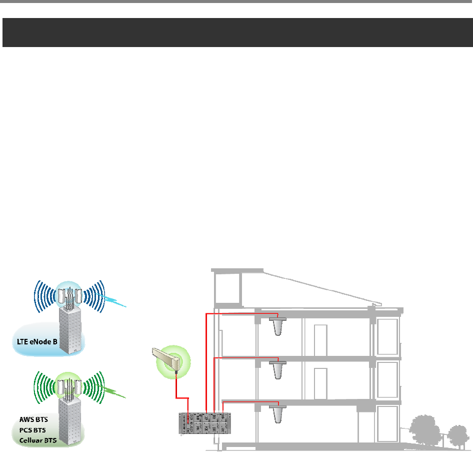
2.1 SmartCell Repeater Service Network Configuration
The SmartCell Modular Repeater is designed to improve coverage and capacity of LTE, PCS,
Celluar, and AWS services. The repeater can provide in building coverage for all trouble areas.
SmartCell is easy to install, has remote status monitoring and control functions (NMS System)
via a wired line and wireless modem.
<Figure 1> In-building Repeater Service Organization
User Manual
SmartCell Repeater
8
2.2 System Design and Operation
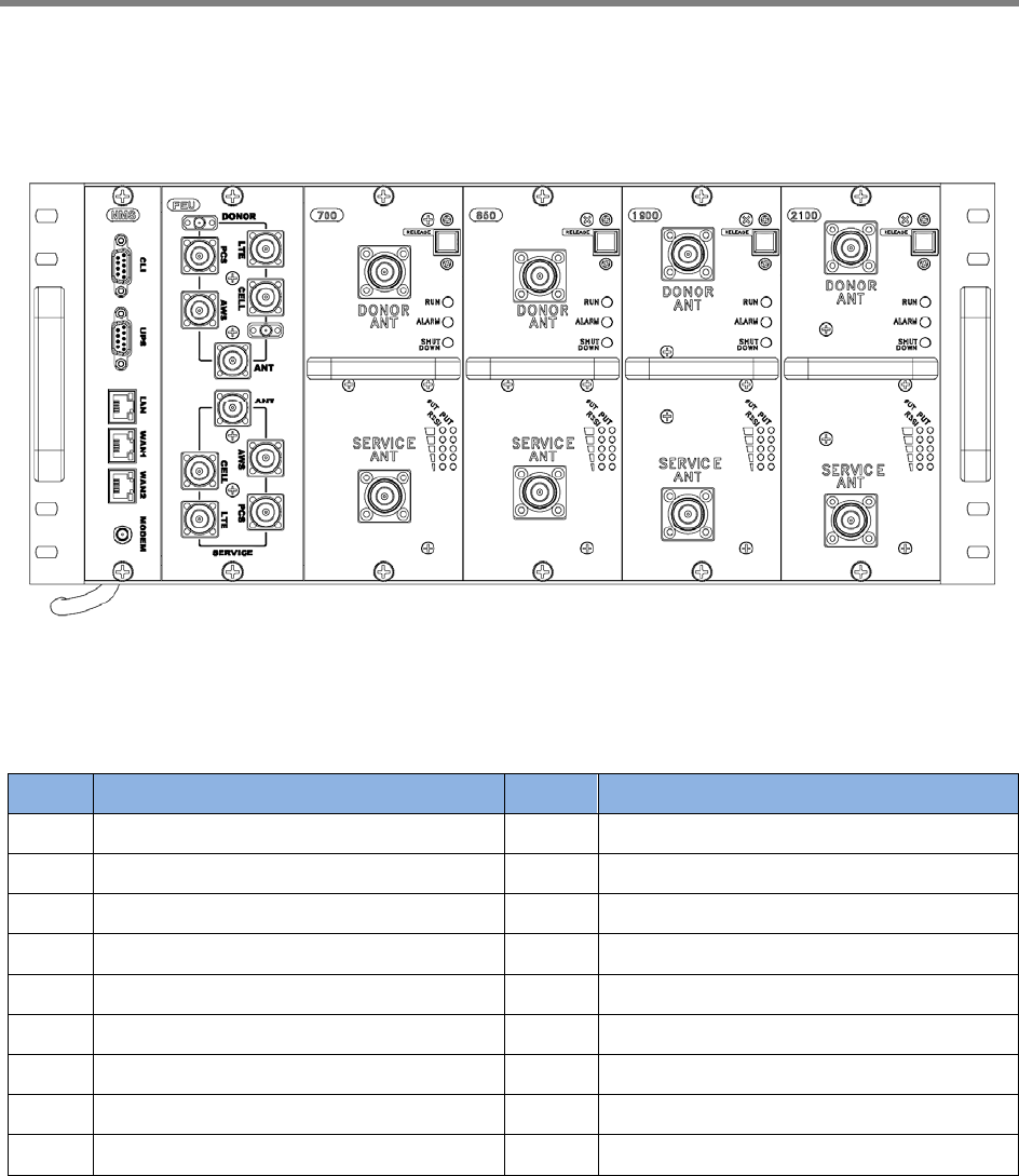
2.2.1 System Design
<Figure 2> SmartCell Repeater Front Design
NO. PART NO. PART
1 SNMP 10 WAN 1 Port
2 FEU (Cavity Filter), optional 11 WAN 2 Port
3 Service Unit #1 12 Modem Antenna Connection Port
4 Service Unit #2 13 Donor Port(s)
5 Service Unit #3 14 Service Port(s)
6 Service Unit #4 15 Status LED (RUN/Alarm/Shutdown)
7 CLI 16 Input / Output LED
8 UPS 17 Release Button
9 LAN Port
7
8
1
9
10
11
12
2 3 4 5 6
13
14
16
15
17
User Manual
SmartCell Repeater
9
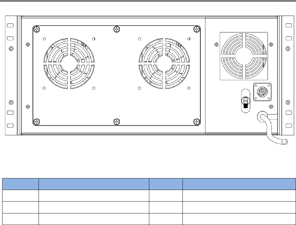
<Figure 3> SmartCell Repeater Back Design
NO. PORT NO. PORT
1 Main FAN Assembly 4 DC 12V Output Connection
2 PSU FAN 5 Power Cable
3 Main Power Switch
1
2
3
5
4
User Manual
SmartCell Repeater
10
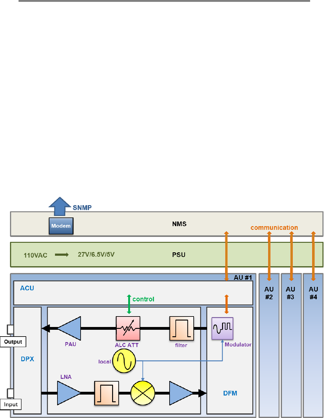
2.2.2 Downlink/ Uplink Path
The user may select frequency bands according to the site conditions. After receiving a signal
from the donor antenna(s), the repeater improves it and sends a securely isolated signal out to
the service antenna(s). Each amplifier module has its own separate digital filter module (DFM).
The amplifier module consists of a down converter, up converters, cavity filter, and power
amplifier (PAU).
In the Downlink Path:
1. RF Signal is received from the donor antenna through the input port.
2. The signal is then converted from RF to IF,
3. The IF signal is digitized by the DA converter,
4. The digital signal is filtered by the DFM (FPGA),
5. The modulator converts the digital signal to an analog RF signal and transmits to
the amplifier.
6. Amplifier outputs final signal to service antennas at desired output power.
Uplink path works in reverse order.
<Figure 5> SmartCell Repeater Block Diagram
DFM
User Manual
SmartCell Repeater
11
2.2.3 700MHz Frequency Selection
<Figure 6> 700MHz Band Frequency
The 700MHz AMP module complies with LTE 3GPP requirements, where a maximum of two non-
contiguous block configurations are available. Each block is adjustable per 5 MHz.
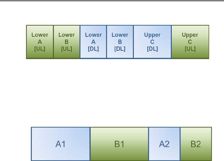
2.2.4 850MHz Frequency Selection
<Figure 7> 850MHz Band Frequency
The 850MHz AMP module provides Cellular service, where a maximum of two non-contiguous
block configurations are available. Each block is adjustable to the following bandwidth
configurations:
A1: 11MHz
B1: 10MHz
A2: 1.5MHz
B2: 2.5MHz
User Manual
SmartCell Repeater
12
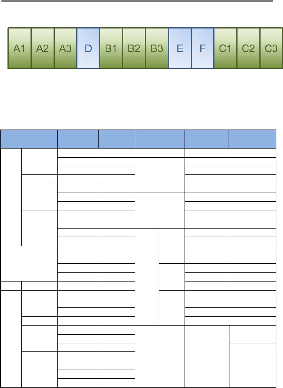
2.2.5 1900MHz Frequency Selection
<Figure 8> 1900MHz Band Frequency
The 1900MHz AMP module complies with PCS Band blocks, where a maximum of three non-
contiguous filtering configurations are available. Each sub block is adjustable per 1.25MHz
bandwidth steps up to 20MHz. The Following table shows user selectable channel numbers.
BAND DL CENTER
[MHz] CHANNEL BAND DL CENTER
[MHz] CHANNEL
A
A1 1931.25 25 guard 1965 700
1932.5 50 E 1966.25 725
1933.75 75 1967.5 750
guard 1935 100 1968.75 775
A2 1936.25 125 guard 1970 800
1937.5 150 F 1971.25 825
1938.75 175 1972.5 850
guard 1940 200 1973.75 875
A3 1941.25 225 guard 1975 900
1942.5 250
C
C1 1976.25 925
1943.75 275 1977.5 950
guard 1945 300 1978.75 975
D 1946.25 325 guard 1980 1000
1947.5 350 C2 1981.25 1025
1948.75 375 1982.5 1050
guard 1950 400 1983.75 1075
B
B1 1951.25 425 guard 1985 1100
1952.5 450 C3 1986.25 1125
1953.75 475 1987.5 1150
guard 1955 500 1988.75 1175
B2 1956.25 525
G 1992.5
1225
1957.5 550
1958.75 575 1250
guard 1960 600
B3 1961.25 625 1275 1962.5 650
1963.75 675
User Manual
SmartCell Repeater
13
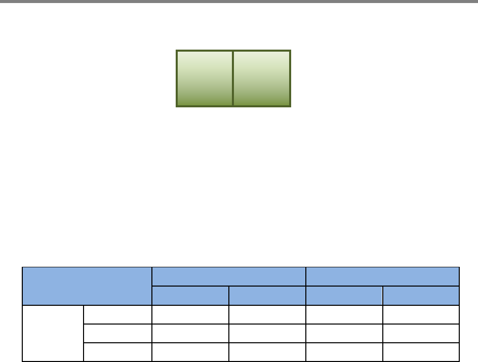
2.2.6 2100MHz Frequency Selection
<Figure 9> 2100MHz Band Frequency
The 2100MHz AMP module complies with CDMA band requirements, where two block
configurations are available. In order to set contiguous band F, check ‘Band F1’, ‘Band F2’ and
‘contiguous’ button in the WEB UI. In order to set Band F1 or Band 2 do not check ‘contiguous’
button in WEB UI. Band F configuration is as follows:
BAND Downlink Uplink
Start Stop Start Stop
F
F1 2145.15 2149.85 1745.15 1749.85
guard - - - -
F2 2150.15 2154.85 1750.15 1754.85
F1 F2
User Manual
SmartCell Repeater
14
3. SETUP
3.1 Equipment Needed for Repeater Setup
Paramete
r
Item
Q
uantit
y
Remark
Major Component SmartCell Repeater 1 EA Provided by GST
Additional
Components
Wall Mountin
g
Bracket
CD which contains User Manual
and Installation Guide
Ethernet Cable 6.6ft (2m)
Ground Cable 6.6ft (2m)
Ground Sems Screw M4 x 8mm
Bracket Sems Screw M5 x 10mm
Lag Screw 12.7mm x 50.8mm
FEU-AMP RF cable
FEU-Wall Bracket RF cable
Modem-FEU RF Cable
1 EA
1 EA
1 EA
1 EA
4 EA
20 EA
4 EA
8 EA
2 EA
1EA
Provided by GST
Antenna Donor ANT
Server ANT
1 EA
1 EA Not Included
RF Cable Antenna connection Cable
T
BD Not Included
T
estin
g
and Measurin
g
Equipment Spectrum Analyzer 1 EA Not Included
3.1.1 Check points before turning on the Repeater
1) System Power Check: AC electrical power to the repeater should be 110V. Input
electricity only after power verification.
2) Input RF Signal Range: Optimal input RSSI into the repeater is -57dBm ~ -27dBm for
700MHz/850MHz/1900MHz/2100MHz. User should verify input condition of Donor ANT. If the
input RSSI exceeds -27dBm, then external attenuators should be added.
3) Isolation check between DONOR/SERVER ANT: Isolation condition of this equipment is
105dBc (Gain+15dB). The User should check this condition before installation.
User Manual
SmartCell Repeater
15
3.1.2 Ready for Service
1. Check points before Service:
a. Verification of system installation:
- Electricity, In/Out antennas, cable connections, and equipment mounting.
b. Verification of system accessories:
- User should check all necessary accessories.
c. Check received signal level:
- User should check whether environmental conditions are in accordance with system
specifications to ensure the system operation will be optimized.
2. Check points after Service:
a. Check external LEDs
1) RUN: Green light ON (Off: all lights off).
2) ALARM: Green light in normal status, Red light in alarm.
3) SHUT DOWN: Green light in normal status, Red light in Shutdown.
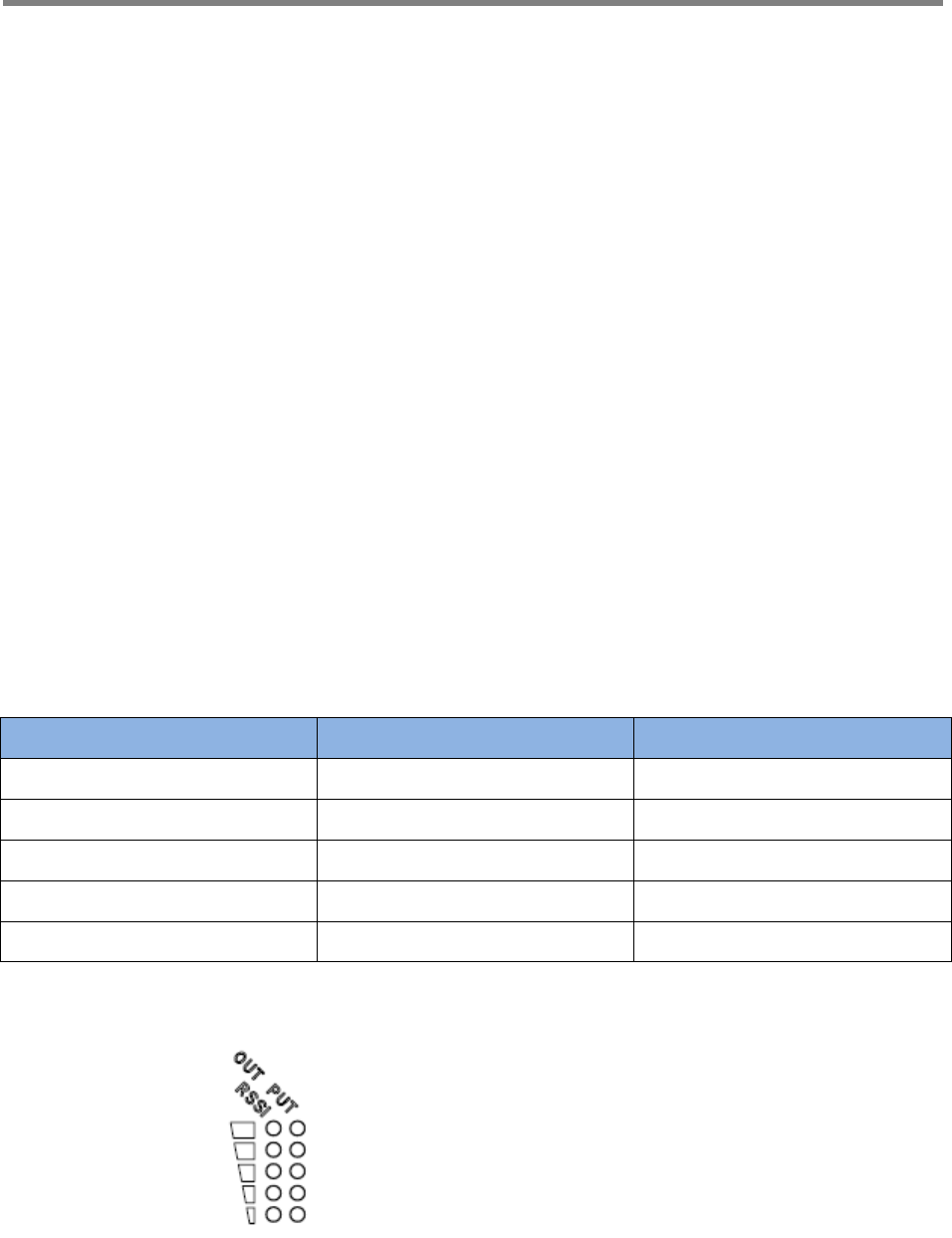
3.1.3 Signal Strength LED Check
Number of LED bars Input Signal Level Output Power Signal Level
LED 1 bar Less than -86dBm Less than +5dBm
LED 2 bars -85dBm ~ -79dBm +6dBm ~ +10dBm
LED 3 bars -78dBm ~ -72dBm +11dBm ~ +15dBm
LED 4 bars -71dBm ~ -65dBm +16dBm ~ +20dBm
LED 5 bars More than -64dBm More than +21dBm
Figure 9> Modular Repeater Front LED
4.2 Setting up the Repeater

User Manual
SmartCell Repeater
16
3.2.1 Quick GUI/Configuration
Use the following steps to commission the Repeater after all the cabling and antennas are fixed
in place and the Repeater is supplied with proper electrical power. The repeater will need a
stable Downlink RSSI input level in the range of -85dBm to -60dBm.
1. Connect your laptop to the LAN port on the repeater with a Crossover Ethernet cable.
2. Verify your laptop has all wireless connections turned off and is set to obtain an IP
address automatically, or you may use a fixed IP address: 172.16.6.82, with a Subnet
Mask of 255.255.255.252, no default Gateway.
3. Open web browser and enter: 172.16.6.81.
4. User name: admin.
5. Password: admin.
3.2.2 Quick Setup
1. Go to the RF Configuration page.
2. Before the Amplifier (HPA) can be turned on, set the Uplink and Downlink attenuation
(ATT) to the maximum value and click Apply.
3. Select the correct Band Block and set the ALC Downlink and Uplink Limits to the desired
level and click Apply. (To adjust the Output Power, change the ALC Downlink and Uplink
Limits to the desired levels).
4. To check the Repeater’s status, click on the Status page.
5. To change the Repeater’s gain, adjust the Uplink and Downlink attenuation in equal
amounts not more than 5dB at a time and click Apply.
3.3 WebUI Ranges Table
GUI Feature Range Description
Downlink and Uplink Output
Power Display Below 0dBm to 35dBm The output Power of the Repeater
Downlink Low RF Power 2dB to 10dB Threshold for Low RF Power
Downlink and Uplink
Attenuation Control 0dB to 30dB Reduces Gain Internally
Downlink and Uplink ALC Limit 0dBm to 33dBm Limits Output Power
Downlink RSSI Display -100dBm to -27dBm Downlink Receive Level at Donor
Antenna Port
Downlink Low RSSI -93dBm to -57dBm Threshold for Low RSSI
Downlink and Uplink AMP On/Off High Powered Amplifier
User Manual
SmartCell Repeater
17
Control
Gain Balance Control On/Off Equalizes Uplink and Downlink Gain
Gain Balance Value 0dB to 15dB Subtract Uplink Gain by G/B Value
Shutdown Control On/Off Shutdown if Major Alarm is Reported
Auto Gain Setting On/Off Automatic Gain Setting for the Repeater
Auto Oscillation Control On/Off Prevents Oscillation
Temperature Display 32 to 260.6 Degrees Internal Repeater Temperature
AMP Temperature Upper Limit 0 to 299 Degrees Threshold for Temperature Alarm
Band Blocks Used/Bandwidth Each AMP The Channel the Repeater will be using
Delay Alarm Report 0 or 5 Minutes Time Delay of Reporting after Alarm is
Detected
3.4 Troubleshooting
In case of abnormal operation, technician should diagnose abnormality via remote access or
directly connecting to repeater using Ethernet cable. If technician is required to conduct repairs
due to major alarm, repeater should first be powered off, and then technician should prepare
the proper measurement equipment before trying to fix the problem.
3.4.1 Simple Troubleshooting Method
1) Verify LED Status, both on external LED’s as well as internal module LED’s
- Normal operation: Green light on. Alarming: Red LED on.
2) Technician should check external and internal connectors to ensure all connections are tightly
secure. These connectors should be cleaned regularly.
3) If technician thinks there is a serious problem, call technical support.
1-866-9-GST-USA (1-866-947-8872)
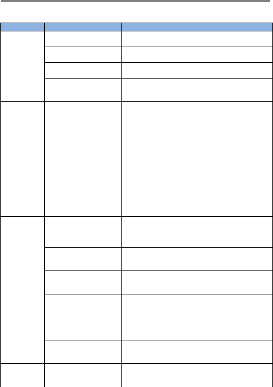
3.4.2 Alarm Information
Alarm
Name What causes this
alarm Troubleshooting Methods
Downlink
Spurious
emissions
out of spec
Downlink Output Pow
er exceeds Downlink
Upper Limit
* The Downlink Output Power should not exceed the m
aximum composite power spec for this unit.
* If the Downlink Output Power is not exceeding the co
mposite power spec for this unit, try to increase the Do
wnlink Upper Limit on the RF Configuration Page.
* Add equal amounts of Uplink and Downlink attenuati
on until the Downlink Output Power is less than the Do
wnlink Upper Limit.
* Set the ALC Downlink Limit on the RF Configuration P
age to a value lower than the Downlink Upper Limit
Downlink Har
dware failure Downlink path gain is
6dB less than RSSI pl * By default, if the Downlink Low Output Variance is se
t to 10dB, the Repeater will not report this alarm.
User Manual
SmartCell Repeater
18
us Output Power * Increase the Downlink Low Output Variance on the R
F Configuration Page.
Downlink Do
nor power to
o low
Input RSSI from Dono
r site is 8dB less than
Downlink Low Input Li
mit
* By default, if the RSSI Lower Limit is set to -
93dBm, the Repeater will not report this alarm.
* Decrease the Downlink Low RSSI Limit level on the R
F Configuration Page.
* Increase the RSSI level into the Repeater.
Downlink VS
WR
When the VSWR Ratio
on the Server Port is
greater than 3 : 1
* "Sweep the line" to check for loose or damaged conn
ectors and/or cabling.
* If after checking the entire Server side, the VSWR ala
rm still exists and the system is working fine, Disable th
e alarm on the Alarm Configuration page.
Downlink Do
nor power to
o high
Downlink Input Power
is greater than -
25dBm
* Check position of the Donor antenna.
* Add attenuator to the Donor port at the highest input
power level.
Downlink Syn
thesizer failur
e
Failure of the
synthesizer Downlink
path
* Turn OFF/ON the System by pressing ON/OFF button
on the back side panel.
* Call GST’s Tech Support Team and exchange the AMP
unit.
Downlink Int
erfere power
exceeded
Out-
band signal is about 1
5dB greater than in-
band signal
* Call GST’s Tech Support Team for further instructions.
Uplink Out of
band emissi
ons out of sp
ec
Uplink Output Power e
xceeds Uplink Upper L
imit
* The Uplink Output Power should not exceed the maxi
mum composite power spec for this unit.
* If the Uplink Output Power is not exceeding the comp
osite power spec for this unit, try to increase the Uplink
Upper Limit on the RF Configuration Page.
* Add equal amounts of Uplink and Downlink attenuati
on until the Uplink Output Power is less than the Uplink
Upper Limit.
* Set the ALC Uplink Limit on the RF Configuration Pag
e to a value lower than the Uplink Upper Limit
Uplink Power
at coverage
port too high
Uplink Input Power is
greater than -25dBm
* Check position of the Coverage antenna.
* Add attenuator to the coverage port or use another d
evice to regulate Uplink output power.
Uplink Synth
esizer failure
(Uplink Hard
ware failure)
Failure of the
synthesizer Uplink
path
* Turn OFF/ON the System by pressing ON/OFF button
on the back side panel.
* Call to GST’s Tech Support Team and exchange the A
MP unit.
Uplink (Down
link) Softwar
e failure
Alarming in DFM of
the amplifier unit
* Turn OFF/ON the System by pressing ON/OFF button
on the back side panel.
* Call to GST’s Tech Support Team and exchange the A
MP unit.
Oscillation de
tected/Low is
olation
Insufficient isolation is
detected when the R
epeater is at minimum
gain
* Verify that the Donor antenna is on the same side of
the building as the Donor site, and if needed, raise the
Donor antenna up on a pole.
* Change the types of antennas used, such as Yagi to
Corner-
Reflector for outdoors, and Omni to a Panel for indoor
User Manual
SmartCell Repeater
19
use.
* Move the closest indoor service antenna farther away
from the outside Donor antenna.
* Close the repeater door if opened and verify that the
closest indoor coverage antenna is not in the same roo
m as the repeater.
Field Replace
able module
failure
Mismatch of AMP unit
and filter service in DF
M
* Call GST's Tech Support Team to verify all the setting
s are correct.
Tamper Dete
cted
Change of mounting i
nformation in the Syst
em
* Wait 5 minutes to clear alarm automatically.
* If you want to disable, you can on the Alarm Configur
ation page.
Communicati
on Failure Bad connection of NM
S board and AMP unit * SNMP board or AMP unit need to reset.
* Open the rear cover and check the each cable.
Power Suppl
y out of rang
e
The internal Power Su
pply detects improper
Voltage
* If the system is working fine, disable the alarm on th
e Alarm Configuration page.
* Call to GST's Tech Support Team to verify that all the
settings are correct.
Over Temper
ature
Internal AMP tempera
ture exceeds the Tem
perature Limit
* Verify the Temperature Limit is set between 176 °F ~
201 °F on the RF Configuration page. (Default Value is
163°F)
Reset alarm During reset of the un
it, * Wait 30 seconds to clear alarm automatically.
Manual Shut
down
During the shutdown
algorithm after re-
check the system is co
mpletely shut downed
.
* Turn OFF/ON the System by pressing ON/OFF button
on the back side panel.
* Reset AMP unit in WebUI.
FAN FAN Failure * Replace FAN.
User Manual
SmartCell Repeater
20
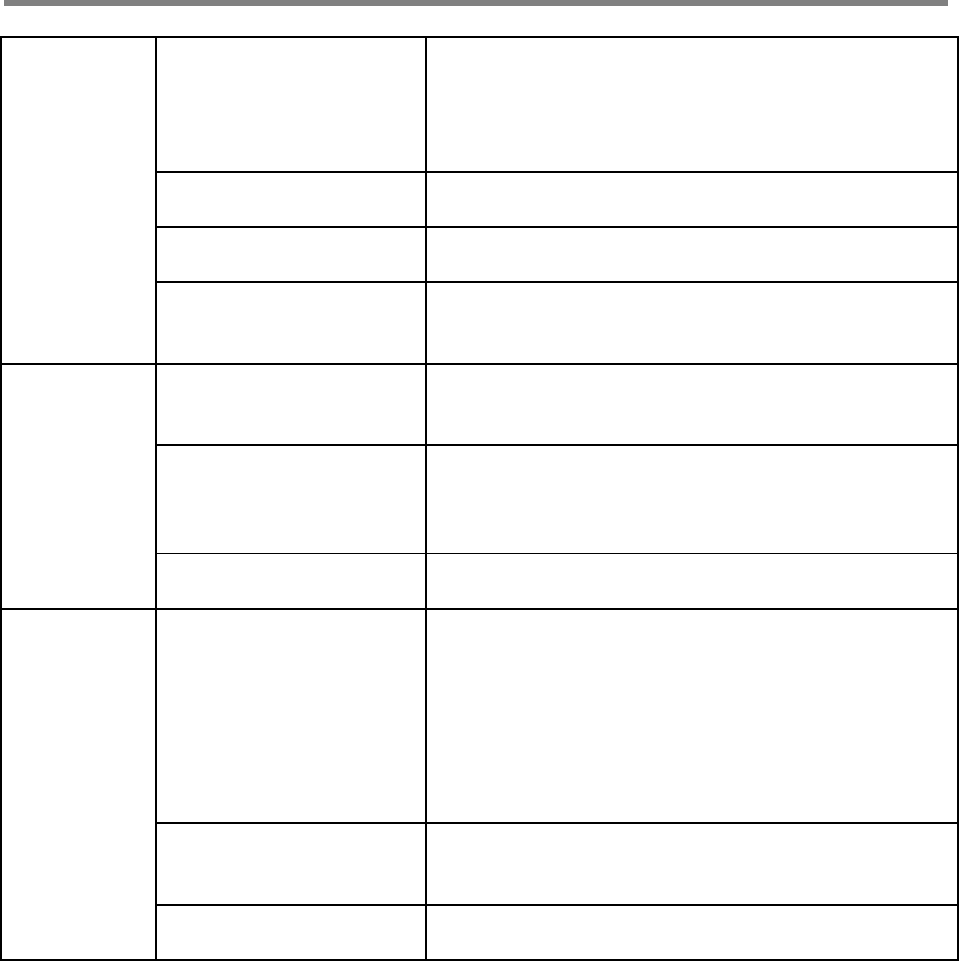
3.4.3 Troubleshooting Guide Related to RF
Item Check Point Troubleshooting
Check before
system
operation
System input power
range -Downlink: -100dBm ~ -27dBm
-Uplink: -100dBm ~ -27dBm
System gain
(DL/UL) - 60dB ~ 90dB
Output power
at server port - Downlink: 33dBm ± 2dB
- Uplink: 33dBm ± 2dB
Check points before open
for service
-Please check quantity of all accessories with
specification before you set up
-Fit cable length in accordance with field condition
Check after
system
operation
Check points after open
for service
Check following status;
-Verify the antennas are securely mounted and
pointed in the correct directions
-Connection status between antennas and RF cable
-Verify the Repeater is securely mounted
-Proper AC power status
-Grounding status of electrical circuit
-Coaxial cable (RF) construction status
-Connectors and combiners connection status
-Cable connection status against leakage of water
When
repeater
does not
work
properly
Check electricity cord
connection status -Re-plug in Adapter cord
When in
alarming
DL VSWR alarm
Check following status;
-Make sure Server Antenna Port is disconnected.
-Reset Adapter upon completing Alarm
troubleshooting
DL over-output alarm -Make sure output power is operating normally
-Reset Adapter upon completing Alarm
troubleshooting
UL over-output alarm -Make sure output level is operating normally
-Reset Adapter upon completing Alarm
troubleshooting
Temperature alarm
Check following status;
-Setting level of maximum temperature limit
-Temperature offset is normal or not
-Circumstances of temperature
-Reset Adapter upon completing Alarm
troubleshooting
RF off -Verify the HPA’s are On
-Reset Adapter upon completing Alarm
troubleshooting
When output
power is no
longer
Technician should verify
category of alarm at the
front side of repeater
-Red light on the Shutdown LED, technician should
troubleshoot the alarm via Notebook computer
User Manual
SmartCell Repeater
21
problem -Technician should
connect antenna with
output port of repeater
-Make sure all connectors
are fastened
-Reconnect the connector
-Change it if the connector is defective
Check the input level -Increase output power or check input change of
BTS side
Check gain of the unit -If the Gain is different from normal level, please
contact GST’s Technical Support
Cable connector loose -It is possible for connectors to get too tight and
damage the equipment or throughput
-Contact installer or service provider
In case of
dropped call
or bad signal
after set up
Check input signal
strength in the service
area
-Increase output power level of repeater by
adjusting attenuation level
If input signal strength is
not a problem, please
check delay of calling
time
-Increase output level of Uplink signal, then set to
optimal level.
Check RSSI signal
strength -Contact network management team or service
provider
In case
output Signal
wavelength is
not shown
flat or looks
like
oscillation
Check connection
fastened between
antenna and cable
(Signal wavelength
should be flat and stable
if technicians shake
CABLE. If not, it is
connection problem)
-If connection is not proper, reconnect cable and
connector and then check the output power again
Input level change or
module overheating
-Check input level from BTS side.
-Check performance of each module (Diagnosed by
GST’s Technical Supportm)
Please check VSWR of
the cable is normal -Change to normal Cable
User Manual
SmartCell Repeater
22
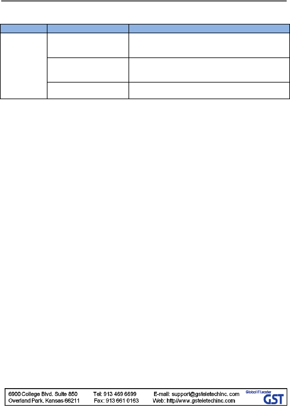
3.4.4 Troubleshooting Guide Related to NMS
Symptom Check Points Troubleshooting
Link Fail
Communication problem -In case of Ethernet, verify IP addressing, DHCP
function, and that cookies are deleted
-Verify that a crossover Ethernet cable is being used
CLI connection, cable
status check
-Make sure 1:1 connection
-Follow instructions in the installation guide for this
connection procedure
CLI connection Check by
USB to serial cable -Verify port number of PC communication
-Check cable connection status
If technician thinks there is a serious problem, call GST’s Technical support.
1-866-9-GST-USA (1-866-947-8872).

MPE Information
ⓒ SAMSUNG Electronics Co., Ltd.
Warning: Exposure to Radio Frequency Radiation The radiated output power
of this device is far below the FCC radio frequency exposure limits.
Nevertheless, the device should be used in such a manner that the potential
for human contact during normal operation is minimized. In order to avoid
the possibility of exceeding the FCC radio frequency exposure limits, human
proximity to the antenna should not be less than 50 cm during normal
operation. The gain of the antenna is 8.0 dBi.The antenna(s) used for this
transmitter must not be co-located or operating in conjunction with any other
antenna or transmitter.