User Manual

PROPRIETARY NOTICE:
This document contains GTECH confidential and proprietary information, know-how, trade secrets,
intellectual property and/or methodologies and is intended only for the use of the individual or entity to
which it is addressed. It may be privileged, and is proprietary, confidential and otherwise exempt from
disclosure under applicable law. This document shall not be modified, reproduced, copied or
transferred without proper prior authorization from GTECH.
Proprietary Notice applies to all pages
APPROVALS DATE
AUTHOR:
Henry Constant
RESPONSIBLE ENGINEER:
Henry Constant
GTECH Aircon Radio (Model GWT154)
User’s Guide
MANUFACTURING ENGINEER:
S. Leigh
QUALITY:
Ray Snow
NO. 96-1886-01E
REV. 1.1
PAGE 1 OF 72
REV DESCRIPTION DATE REVIEWED
1.0 Initial Document June 29, 2011
1.1 Updated Transmit Power settings July 5, 2011

No. 96-1886-01E Rev.
1.1
GTECH Aircon Radio (Model GWT154)
PAGE 2 OF 72
TABLE OF CONTENTS
1.0INTRODUCTION .......................................................................................................... 4
1.1Purpose, Overview & Scope ...................................................................................................... 4
1.2Audience .................................................................................................................................... 4
1.3Applicable Documents ............................................................................................................... 4
2.0Key Features .................................................................................................................... 5
3.0GWT154 Wireless Transceiver Application Circuits .................................................. 6
3.1System Components .................................................................................................................. 6
3.2Electronics Overview ................................................................................................................. 6
3.3Radio Module Pin Definitions ................................................................................................... 7
3.4Mechanical Drawings ................................................................................................................ 9
3.5Mounting Considerations ......................................................................................................... 10
3.6Radio Module Performance Characteristics ............................................................................ 13
3.7Host Board Electrical Characteristics ...................................................................................... 15
3.8GWT154 Recommended Configurations ................................................................................ 15
3.9RF Module Operation .............................................................................................................. 17
3.10Setting Compliance Limits When Using Host Software ......................................................... 20
4.0Wireless Network Infrastructure ................................................................................ 21
4.1Establishing Network ............................................................................................................... 21
4.2Device Joining ......................................................................................................................... 21
4.3Device Security ........................................................................................................................ 22
4.4Non Volatile Settings ............................................................................................................... 24
5.0Wireless Data Transport .............................................................................................. 25
5.1End Device selection ............................................................................................................... 25
5.2Data Security ........................................................................................................................... 26
5.3Acknowledgement ................................................................................................................... 27
5.4Single Unicast MAC Packet .................................................................................................... 28
5.5Fragmented Packets ................................................................................................................. 28
5.6Fragmentation Packet Structure ............................................................................................... 29
6.0Wireless Inter-communication .................................................................................... 32
7.0Host and Peripheral Wired Interfaces ........................................................................ 33
7.1Wired Inter-communication ..................................................................................................... 33

No. 96-1886-01E Rev.
1.1
GTECH Aircon Radio (Model GWT154)
PAGE 3 OF 72
7.2Wired Interface Infrastructure ................................................................................................. 37
8.0User Interface ................................................................................................................ 57
8.1Uninstalled Radio .................................................................................................................... 57
8.2End Device Joining .................................................................................................................. 57
8.3Radio Programming ................................................................................................................. 57
8.4Alternate Configuration and Setup Tool .................................................................................. 57
9.0Host Port Configuration Sequences ............................................................................ 59
9.1Coordinator Configuration, Network Start and Joining .......................................................... 59
9.2Coordinator Configuration Setting Firewall Address Mask .................................................... 63
9.3Coordinator Configuration – Get End Device Statistics .......................................................... 64
9.4Coordinator Configuration – Setting End Device Parameters ................................................. 65
9.5Peripheral Configuration, Status .............................................................................................. 66
10.0Agency Statements ........................................................................................................ 67
10.1Federal Communication Commission Interference Statement ................................................ 67
10.2Industry Canada Statements .................................................................................................... 68
10.3OEM Responsibilities to comply with FCC and Industry Canada Regulations ...................... 70
10.4End Product Labelling ............................................................................................................. 71
11.0Contacting GTECH Corporation ................................................................................ 72

No. 96-1886-01E Rev.
1.1
GTECH Aircon Radio (Model GWT154)
PAGE 4 OF 72
1.0 INTRODUCTION
1.1 Purpose,Overview&Scope
The purpose of this document is to provide details regarding the use of the GWT154
transceiver module as a cable replacement between GTECH online lottery terminals and
associated peripherals. The GWT154 transceiver module is based on the IEEE 802.15.4-2006
standard, this wireless link provides a point to multipoint peripheral bus with low latency and
modern security features.
The link operates in the 2.4GHz band with low power, making it suitable for license-free
worldwide operation.
The link will use AES 128 bit authentication and packet encryption available as part of the
802.15.4 standard. It will also use EUI-64 (MAC address) filtering to keep rogue devices off
the network. It relies on the GTECH online lottery terminal for initialization and authorization
of End Device peripherals. This allows GTECH the ability to integrate the local security
measures with field service installations and manufacturing operations, as well as to provide
security audit trails, without on-site technical staff.
This document describes the electrical and wiring considerations when interfacing the
GWT154 module with a GTECH online lottery terminal and a peripheral.
Peripheral devices include (but are not limited to) the following:
Ticket Scan
Accutherm Supreme and Accutherm Ultra printers
Customer Display Units
Jackpot Signs.
1.2 Audience
This document is intended to be read by engineers and technical management. A general knowledge
of common engineering practices is assumed.
1.3 ApplicableDocuments
96-1886-00E, GTECH Wireless Peripheral Transceiver, Rev 3.1, June 2, 2010
96-0258-01, Spec Protocol 485 Bus Packet, Rev D
96-0320-01, RS-485 Physical Interface Specification, Rev C, September 2, 2003
33-0154-01E, System Diagram GWT154, Rev 1, June 3, 2011

No. 96-1886-01E Rev.
1.1
GTECH Aircon Radio (Model GWT154)
PAGE 5 OF 72
2.0 KEY FEATURES
802.15.4-2006 compliant transceiver operating in the unlicensed Industrial, Scientific, and
Medical (ISM) frequency band of 2.400 – 2.4835 GHz.
Lost Link Prevention – The GWT154 provides a failsafe timeout in the event the GTECH
Terminal doesn’t receive a response from the peripheral.
The GTW 15.4 provides security:
o Uses AES 128 bit authentication and packet encryption
o Uses EUI-64 (MAC address) filtering to keep rogue devices off the network
o Uses the GTECH Terminal for initialization and authorization of End Device
peripherals. This allows GTECH the ability to integrate the local security measures with
field service installations.
o Uses a peripheral addressable firewall to exclude single or multiple peripherals from
accessing the GTECH 485 Bus
The GWT154 supports the GTECH 485 Packet Protocol over the following data interfaces:
o GTECH RS-485 (Half duplex 4-wire, DB-9)
Two pairs of uni-directional lines.
The terminal always transmits on Tx± and receives on Rx±.
Female 9-pin DSUB receptacle.
Reset-on-Break support in accordance with [3].
o USB 2.0 Type B Mini
o Internal 3.3V UART
The following form factors are supported.
o Pinned module – For new embedded designs or as an OEM module replacement
1.0” (W) x 1.33” (L) (UART two 1x10 headers)
o Dongle – For existing or legacy GTECH online terminals or RS-485 peripherals
2.1” (W) x 2.6” (L) (RS-485 DB9F or USB 2.0 Type mini B interface)
The transceiver will be used only indoors.
RF power will be software selectable at 10mW (10dBm) or 63mW (18dBm) during operation
with a 1dB resolution.
An internal chip antenna is on the circuit board along with a software switchable RF connector
for an optional external antenna connection.
The transceiver derives its power from the following options.
o Specific interface ports in the dongle configuration.
RS-485: +12V and/or +5V, 300 mA available.
USB: +5V BUS supply
o PCB pins in the OEM replacement module configuration.
o DC power connector – A wall mount power transformer with integral 6 foot cord.
Storage Environment
o Temperature: -40 to +80°C.
o Rate of change: 20°C per minute
o Humidity: 10 to 90%, noncondensing.
Operating Environment
o Temperature: -40 to +80°C.
o Rate of change: 10°C per minute
o Humidity: 10 to 90%, noncondensing.
Radiated and conducted limits meet FCC part 15 and Industry Canada ICES-003 emission

No. 96-1886-01E Rev.
1.1
GTECH Aircon Radio (Model GWT154)
PAGE 6 OF 72
standards.
The product complies with all current European Union Directives applicable to CE marking.
RoHS compliant.
3.0 GWT154 WIRELESS TRANSCEIVER APPLICATION CIRCUITS
The Radio Module is a standalone RF module with an optional external dipole antenna. It is intended
to be an RS-485 cable replacement for new GTECH embedded applications or as an OEM replacement
module for our suppliers of GTECH equipment.
For existing or legacy GTECH products, the Radio Module should be mounted to the Host Board via
the two 1x10 headers. These mated boards are enclosed in a plastic housing and this constitutes the
Dongle solution.
3.1 SystemComponents
The GWT154 Wireless Transceiver consists of the following components:
Radio module (51-1884-01E) – Standalone for new designs or as an OEM replacement
module
o Radio Module Label (14-2027-02E)
o Optional External Antenna with Cable
Carrier/Host board (51-1885-01E) – Optional for legacy products
Plastic enclosure (Dongle) – Optional for legacy products
o Plastic Parts (16-2104-502E & 16-2105-502E)
o Dongle Label (14-2027-01E)
Wall mount Power Supply – Optional for legacy products
o US: 50-0347-01E
o UK: 50-0347-02E
o EU: 50-0347-03E
Interface cables – Optional for legacy products
o USB A to USB mini B Cable (32-1743-01E)
o RS-485 Straight pinned Cable (32-1344-03E)
o RS-485 Crossed pinned Cable (32-1744-01E)
Note: Optional components are used based on the specific installation requirements.
3.2 ElectronicsOverview
The electronic design solution for this product consists of two PC boards.
Radio module. This stand-alone module will be the solution for new embedded designs
or for an OEM module replacement. The two 1 x 10 pin headers will be the interface to
the radio module for all configurations. The radio module will consist of the Texas
Instruments CC2530 SOC, the Texas Instruments CC2591 Front end module, a
Johanson 2450AT18A100 chip antenna, and a Hirose U.FL coaxial RF connector.
A host board will consist of the GTECH RS-485 interface, USB 2.0 interface, DC
power jack, and interface connectors to plug the radio module into. The combination of
these two boards with the plastic enclosure will provide the solution for the dongle.

No. 96-1886-01E Rev.
1.1
GTECH Aircon Radio (Model GWT154)
PAGE 7 OF 72
Figure 1 – Block Diagram
3.3 RadioModulePinDefinitions
The communication between the Host board and the Radio module is via UART.

No. 96-1886-01E Rev.
1.1
GTECH Aircon Radio (Model GWT154)
PAGE 8 OF 72
Figure 2 - The interface pin numbering (top side view)
Pin
#
NAMEDESCRIPTION
1VCC3.3Vdc
2UTXUARTdataoutfrommodule
3URXUARTdataintomodule
4NCNoConnect.ModuleoptiontoconnecttoportP1_5
5RESET_NModuleReset
6NCNoconnect.ModuleoptiontoconnecttoportP2_0
7P2_2/DCCC2530DebugClock.Forprogramminganddebuggingofradiomodule
CC2530
8P2_1/DDCC2530DebugData.Forprogramminganddebuggingofradiomodule
CC2530
9DTR_NDataTerminalReadycommunicationline
10GROUNDGround
11NCNoConnect
12CTS_NCleartoSendFlowControl
13SLEEP_NModulestatusindicator
14NC/P1_6/UTX1NoConnect.ModuleoptiontoconnecttoalternativeUARTTXD
15NC/P1_7/URX1NoConnect.ModuleoptiontoconnecttoalternativeUARTRXD
16RTS_NRequesttoSendFlowControl
17TX_ENRS‐485driverenableoutputline.Disablesbusdriverduringhardware
reset
18NCNoConnect.ModuleoptiontoconnecttoportP1_4
19NCNoConnect.ModuleoptiontoconnecttoportP1_2
20STATUS_LEDNoConnect.ModuleoptiontoconnecttoportP1_0
Table 1 - The interface pin assignments and definitions

No. 96-1886-01E Rev.
1.1
GTECH Aircon Radio (Model GWT154)
PAGE 9 OF 72
3.4 MechanicalDrawings
Figure 3 - Radio Module (1.0” x 1.33”) (antenna option not shown)
Figure 4 - Host Board with Radio Module (1.6” x 2.25”)

No. 96-1886-01E Rev.
1.1
GTECH Aircon Radio (Model GWT154)
PAGE 10 OF 72
Figure 5 - Plastic Enclosure (2.1" x 2.6")
3.5 MountingConsiderations
The GWT154 Radio Module was designed to mount into a receptacle (socket) and therefore does not
require any soldering when mounting it to a board.
3.5.1 NewGTECHEmbeddedApplicationsorOEMReplacementModules
For new designs, the footprint design on the host/carrier board will depend on the host/carrier board
requirements, desire for compatibility with other GWT154 series modules, and the desired antenna.
(Note: Figure 6 – Example of the GWT154 Radio Module mounting to a Host/Carrier Board does not
show the external antenna option.)

No. 96-1886-01E Rev.
1.1
GTECH Aircon Radio (Model GWT154)
PAGE 11 OF 72
Figure 6 – Example of the GWT154 Radio Module mounting to a Host/Carrier Board
3.5.2 LegacyGTECHProducts
For existing or legacy GTECH products the Radio Module mounts to the Host Board and is enclosed
in a plastic housing, referred to as the Dongle. This Host board provides RS-485 and USB interface
connectors and an optional DC power connection. It uses two 10-pin receptacles to receive the Radio
Module.
The receptacles used on the Host Board are manufactured by Samtec, CUI Inc. and TYCO. Several
other manufacturers provide comparable mounting solutions; however, GTECH currently uses the
following receptacles:
Surface mount 10 Pin 2mm Single Row Receptacles
o Samtec P/N: SMM-110-02-S-S (or equivalent)
Through hole 2.0mm DC Power Jack
o CUI Inc. P/N: PJ-102A (or equivalent)
Surface-mount 5 Position Right Angle Mini B TYPE USB Jack
o Samtec P/N: MUSBR-05-F-O-B-SM-A
Through-hole 9 Pin Right Angle Female DSUB Connector
o TYCO P/N: 5747844-3

No. 96-1886-01E Rev.
1.1
GTECH Aircon Radio (Model GWT154)
PAGE 12 OF 72
Figure 7 - Radio Module mounted to the Host Board
Figure 8 - Dongle Assembly (Top and Bottom view)

No. 96-1886-01E Rev.
1.1
GTECH Aircon Radio (Model GWT154)
PAGE 13 OF 72
3.6 RadioModulePerformanceCharacteristics
ParameterMinTypical MaxUnit
SupplyVoltage(VCC)2.73.33.6Volts
SupplyCurrent250mA
OperatingTemperature‐40 80°C
Temperaturerateof
change
10°C/min
OperatingHumidity10 90%RH
VoltageonanyIOpin‐0.3VCC+0.3 Volts
Table 2 – Operating Conditions
ParameterMinTypical MaxUnit
RFFrequency24002480MHz
RFChannels16
RadioBaudRate 250kbps
RadioChipRate 2Mcps
Table 3 - General Radio Characteristics
ParameterMinTypicalMaxUnitConditions
ReceiverSensitivity‐99‐95‐85dBm1%PER,802.15.4‐2006
ReceiverMaximum
Input‐2010dBm1%PER,802.15.4‐2006
ReceiverCurrent2730mA
AdjacentChannel
Rejection(±5MHz)035dBWantedsignal2440MHzat‐82dBm,
802.15.4modulatedinterferer,PER=1%
AlternateChannel
Rejection(±10MHz)3049dBWantedsignal2440MHzat‐82dBm,
802.15.4modulatedinterferer,PER=1%
ChannelRejection(≥
±20MHz)3056dBWantedsignal2440MHzat‐82dBm,
802.15.4modulatedinterferer,PER=1%
Table 4 - RF Receive Specifications (At 25°C – 3.3VDC)

No. 96-1886-01E Rev.
1.1
GTECH Aircon Radio (Model GWT154)
PAGE 14 OF 72
ParameterMinTypical MaxUnitConditions
TransmitOutputPower 1618dBmTXPOWER=0xD5
MinimumTransmit
OutputPower 10dBmTXPOWER=TBD
TransmitCurrent
(100mW) 165200mATXPOWER=0xF5(20dBm
transmitoutputpower)
TransmitCurrent
85mATXPOWER=TBD
(10mW)
TransmitConducted
Harmonics ‐20dBcTXPOWER=0xF5(Relative
tofundamental)
ErrorVectorMagnitude
(EVM) 1335%TXPOWER=0xF5(20dBm
outputpower)
CarrierCenterFrequency‐40 40ppm‐40°Cto+80°C
Table 5 - RF Transmit Specifications (At 25°C – 3.3VDC unless noted)
ParameterLimitConditions
MinimumOperatingBandwidth >500kHz
PeakOutputPower<1W
AntennaGainDeratingLimit<6dBi
SpuriousEmissions(standard)20dBc100kHzmeasurement
bandwidth–upto10thharmonic
SpuriousEmissions(15.205
restrictedbands)
15.209general
emissions
Detectortypeandbandwidth
specifiedPart15.35–upto10th
harmonic
PowerSpectralDensity8dBm/3kHzConductedtoantenna
RadioFrequencyExposure
ClassificationMobiledevice
AntennaRequirement
Fixedantennaor
non‐standard
connector
Table 6 - Primary EMC Certification Requirements FCC Part 15 – Modular Certification

No. 96-1886-01E Rev.
1.1
GTECH Aircon Radio (Model GWT154)
PAGE 15 OF 72
ParameterConditions
StorageTemperature‐40°Cto+80°C
StorageTemperaturerateof
change20°C/minutemaximum
StorageHumidity10%to90%RH,non‐
condensing
Table 7 - Environmental Requirements
3.7 HostBoardElectricalCharacteristics
ParameterMinTypicalMaxUnit
InputVoltage416Volts
OutputCurrent 800mA
OutputVoltage33.33.6Volts
Table 8 - Power Supply
ParameterMinTypical MaxUnit
SerialBaudRate2.419.2230.4 kbps
InputSupply
Power512Volts
InputSupply
Current300 mA
Table 9 - RS-485 Serial Bus
ParameterMinTypical MaxUnit
SerialBaudRate2.419.2230.4 kbps
InputSupplyPower512Volts
InputSupplyCurrent300 mA
Table 10 - USB Interface – Fully compliant with USB 2.0 specification
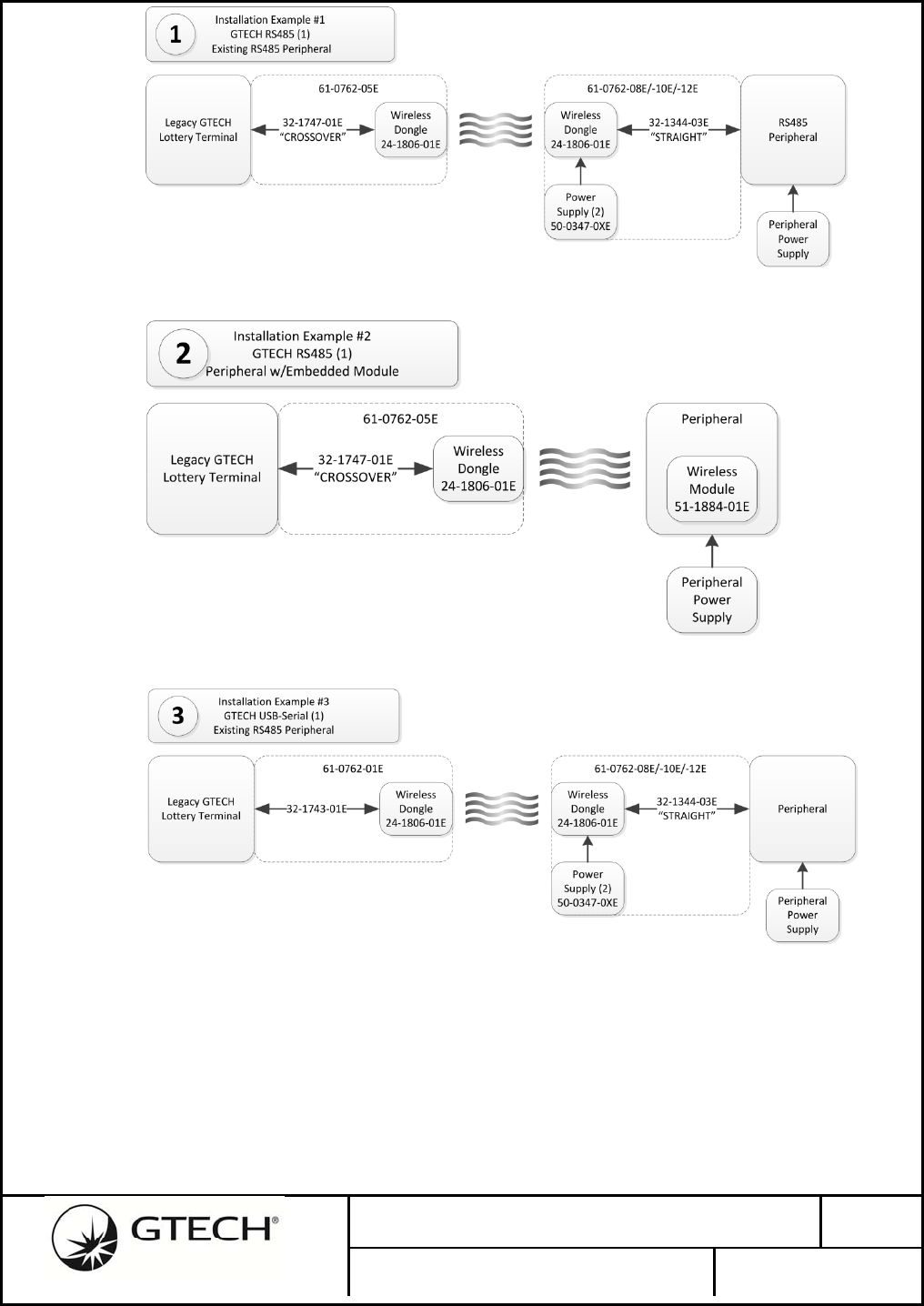
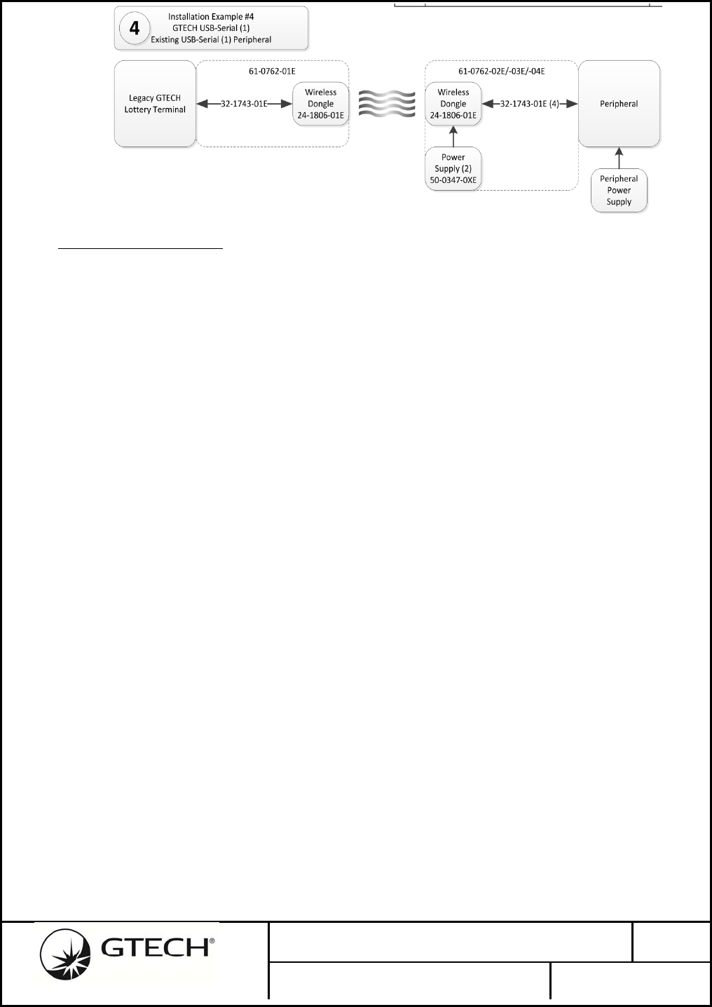
3.8 GWT154RecommendedConfigurations
The following drawings identify typical GTECH installation configurations.
1. Installation of an existing RS485 peripheral into a legacy terminal.
No. 96-1886-01E Rev.
1.1
GTECH Aircon Radio (Model GWT154)
PAGE 16 OF 72
2. Installation of a new RS485 peripheral with the GWT154 embedded radio module (or
modified RS485 peripheral with the GWT154 OEM module replacement).
3. Installation of an existing USB Serial peripheral running GTECH 485 Packet Protocol
into a legacy terminal.
4. Installation of a new USB Serial peripheral running GTECH 485 Packet Protocol with
the GWT154 embedded radio module (or modified peripheral with the GWT154 OEM
module replacement).
No. 96-1886-01E Rev.
1.1
GTECH Aircon Radio (Model GWT154)
PAGE 17 OF 72
3.9 RFModuleOperation
Network is non-beacon enabled 802.15.4 Medium Access Control (MAC).
Security is CCM* with 128-bit encryption keys.
Random network encryption key assigned during initial commissioning.
Peripheral End Devices are at minimum RFD’s with radio always-on.
Data transfers are Direct mode (Indirect not supported).
PAN ID assigned network Coordinator short address.
With the exception of a smaller maximum fragment size and longer/variable ACK latency, GTECH’s
User Data payloads will pass through the wireless link transparently, with virtually the same
GTECH485 protocol presented at both ends.
The PAN Coordinator radio will be attached the GTECH Terminal Host CPU, which is responsible for
initializing and managing the wireless network. Thus, the Terminal can control the RF channel and
other infrastructure parameters, in addition to commissioning peripherals and controlling security.
Only one radio may be connected to any single Terminal serial port. In a system where a single
Terminal Host CPU is to control multiple Coordinator radios, a dedicated Host serial interface port
must be allocated to each Coordinator radio.
By operating the serial host interface at a higher data rate than the GTECH485’s original 19.2Kb, the
latency introduced by packet buffering within the radio modules can be minimized. The radio module
host serial interface will operate at data rates up to 230K BAUD.
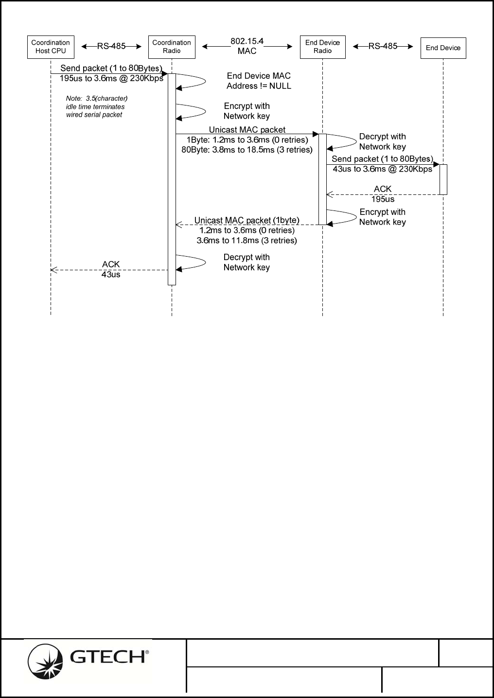
Due to the packet nature of the network, the typical data flow will proceed as follows: The Host CPU
sends a GTECH485 packet to the Coordinator radio via the local wired 485 link. The wired serial
stream is buffered by the Coordinator radio until the entire packet is received. The radio then encrypts
the buffered payload using the network key (randomly generated during wireless network
commissioning). The Coordinator radio then sends the secure packet to the Peripheral connected to the
currently selected End Device radio. The Peripheral’s radio receives the packet, authorizes it, decrypts
its encapsulated payload and sends the entire payload contents to the Peripheral’s Host CPU over the
local 485 wired bus. The End Device radio acts as a local Host CPU proxy to its GTECH485 bus,
sending the packet and receiving one of the ACK responses (ACK, NAK, CAN) from a Peripheral on
the bus. The End Device radio encrypts and sends this ACK back to the Coordinator radio as a secure
packet. The Coordinator receives and decrypts this ACK and, in the role of proxy for the Peripheral,
No. 96-1886-01E Rev.
1.1
GTECH Aircon Radio (Model GWT154)
PAGE 18 OF 72
transmits the ACK back to the Coordinator’s Host CPU.
Figure 9 - Typical Data Flow
3.9.1 BreakProcessing
Legacy GTECH Peripherals recognize a UART Break condition on the GTECH485 bus as a hardware
reset. The Coordinator radio hardware does not include dedicated UART Break detect hardware, but
the Coordinator radio firmware will monitor the GTECH485 bus for a UART Break condition. In
addition, the Host CPU may issue a Break command packet to the Coordinator. In either event, the
Coordinator will broadcast a Break command packet to all the currently Associated End Devices in its
PAN. The End Device radios will software self-reset which, by virtue of the radio’s power-on
initialization sequence, will assert a Break on its wired 485 bus.
No. 96-1886-01E Rev.
1.1
GTECH Aircon Radio (Model GWT154)
PAGE 19 OF 72
Coordination
Host CPU Coordination
Radio
Assert Break or
Send Break Command
Encrypt
Peripheral
End Device
Radio
Decrypt
485 Bus
Hardware Break
RS-485 RS-485
802.15.4
MAC
Broadcast MAC packet
Software
Power-On-Reset
Associate Request
Associate Response
Figure 10 - Break Emulation Sequence
3.9.2 NetworkStartup
The Coordinator will not automatically create the network; it is commanded by the Host CPU to do so.
The Host CPU configures the radio with the required network parameters such as Channel and PAN
before initiating network startup.
3.9.3 EndDeviceAssociation
Devices previously joined to a PAN automatically attempt to associate with their joined network as
soon as they are powered up. The TIMAC will issue an 802.15.4 Beacon Request on every channel
enabled and wait to see if it receives a response from its PAN Coordinator. If an association attempts
fail on all channels, there is a random 10-15 second wait time before the next attempt is made.
3.9.4 802.15.4MACAcknowledgeTransaction
At a low level, each unicast 802.15.4 data transmission is actually a transaction with
acknowledgement. This low-level acknowledgement and retry mechanism serves to increase the
reliability of the wireless link enormously. This functionality is hidden from the application layer and
the user.
The GTECH485 protocol ACK is actually a separate transaction. At the low level it looks exactly the
same as any other data transaction.
3.9.5 TransmitPowerLevel
The TIMAC Application Programming Interface allow setting of the radio’s with a 1dB resolution
No. 96-1886-01E Rev.
1.1
GTECH Aircon Radio (Model GWT154)
PAGE 20 OF 72
between -25dBm and +19dBm. This range is only available on radio modules with the TI CC2591
Power-Amplifier/LNA IC, -25dBm to +11dBm with the CC2590 PA/LAN and the CC2530 by itself is
-25dBm to 0dBm.
3.10 SettingComplianceLimitsWhenUsingHostSoftware
The GTECH485 Test Tool Programming Interface allow setting of the radio’s transmit output power
level with a 1dB resolution between -25dBm and +19dBm. This range is only available on radio
modules with the Power-Amplifier/LNA IC and by itself is limited to -25dBm to 0dBm. Refer to
Error! Reference source not found. for a list of settable transmit output power levels.
Refer to Table 11 - Compliance Limits for setting up the proper compliance limits.
RF
Channel
Max Host RF Power Value
(dBm) TX_PWR Register Value RF Output Power
(mW)
US EU US EU US EU
11 18 11 0xC5 0x75 63.1 12.6
12 18 11 0xC5 0x75 63.1 12.6
13 18 11 0xC5 0x75 63.1 12.6
14 18 11 0xC5 0x75 63.1 12.6
15 18 11 0xC5 0x75 63.1 12.6
16 18 11 0xC5 0x75 63.1 12.6
17 18 11 0xC5 0x75 63.1 12.6
18 18 11 0xC5 0x75 63.1 12.6
19 18 11 0xC5 0x75 63.1 12.6
20 18 11 0xC5 0x75 63.1 12.6
21 18 11 0xC5 0x75 63.1 12.6
22 18 11 0xC5 0x75 63.1 12.6
23 18 11 0xC5 0x75 63.1 12.6
24 18 11 0xC5 0x75 63.1 12.6
25 18 11 0xC5 0x75 63.1 12.6
26 13 13 0x85 0x85 20.0 20.0
Note: When using Optional External Dipole Antenna, RF Channel 26 reduces for FCC Compliance:
26 9 13 0x65 0x85 7.9 20.0
Table 11 - Compliance Limits

No. 96-1886-01E Rev.
1.1
GTECH Aircon Radio (Model GWT154)
PAGE 21 OF 72
4.0 WIRELESS NETWORK INFRASTRUCTURE
4.1 EstablishingNetwork
The PAN Coordinator radio will establish an RF channel, PAN-ID, and network security key with
direction from the Host CPU. Either the Host can force it to use a particular channel, or the radio
module can do an energy scan of all available channels. The Host CPU can also pre-set the PAN-ID or
it can automatically select an unused PAN-ID during network commissioning. The GTECH 802.14.5
wireless network will be implemented as a non-beacon-enabled network.
Often in beacon-less systems, an End Devices may still expect to periodically receive communication
from its Coordinator, often referred to as a heartbeat. In the event an End Device does not receive a
heartbeat within a reasonable period, the End Device may attempt to recover by scanning all channels
and requesting to rejoin its coordinator if found. This feature is not implemented in this design.
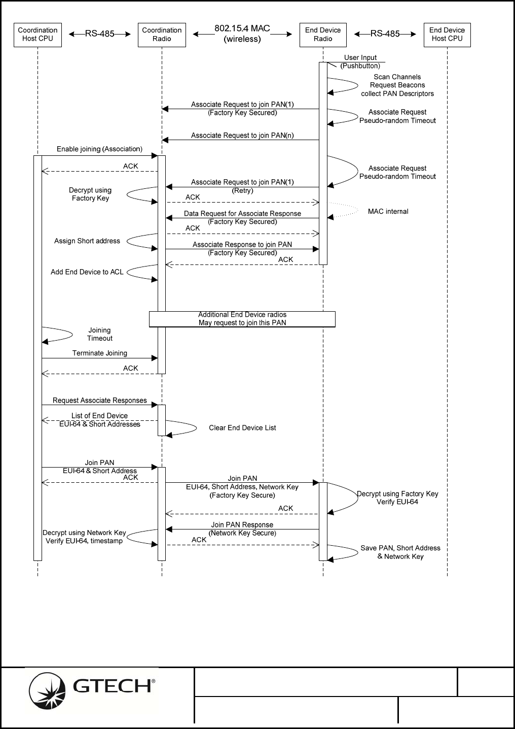
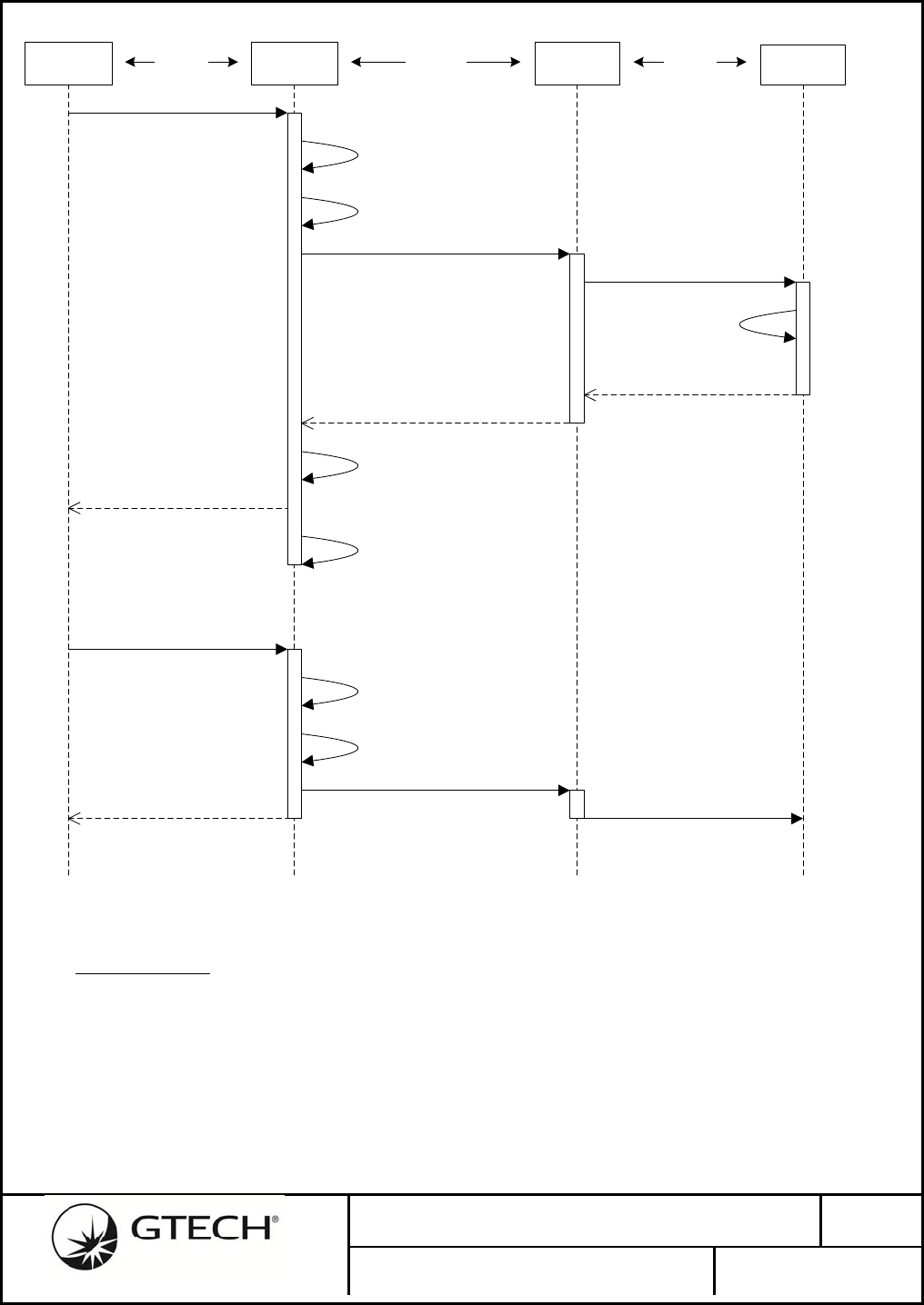
4.2 DeviceJoining
Once a wireless network PAN Coordinator radio has been configured and started, the peripheral radios
may be joined to the PAN. End Device joining will be implemented in accordance to the 802.15.4
standard. Upon pairing activation by the End Device radio’s User Interface, the MAC will scan all
802.15.4 (mapped) RF channels by broadcasting a Beacon Request and registering any successful
responses in a PAN Descriptor list.
Once all enabled channels have been scanned, or the PAN Descriptor list is at maximum, the End
Device will sequentially unicast an Associate Request to each of the PAN Coordinators found in the
Descriptor list, and wait for a response. If it does not receive a response in a random amount of time
(between TBD seconds) it will try the next PAN in the Descriptor list, or if only one PAN, retry. This
time delay will keep the network from being overloaded with requests and reduce the chance of RF
collisions with other End Device radios.
When the Coordinator receives an Associate Request and successfully decrypts using the default
factory key, it saves the End Device’s 64-bit EUI address in a list for later processing by the Host
CPU. Subsequently, the End Device will issue a Data Request to the Coordinator, if the previous
Associate Request was accepted, the Coordinator will reply with an Associate Response. The End
Device has temporarily been joined to the PAN and will remain so until it is later permanently joined
to the PAN, or it times-out.
A failsafe timeout should be employed in the End Device radios during joining to ensure that if the
sequence fails to end in success, the radio discards any joining parameters obtained, and return the
radio to its inactive state.
The Host CPU will determine the length of time the Coordinator will accept Association Requests;
multiple End Devices may be associated during any given joining session. After terminating the
association period, the Host CPU gets the EUI-64 address list from the Coordinator.
Based upon each End Device’s EUI-64, the Host CPU will decide whether that device is allowed on
the PAN. The Host CPU instructs the Coordinator to enter an End Device into the Access Control List

No. 96-1886-01E Rev.
1.1
GTECH Aircon Radio (Model GWT154)
PAGE 22 OF 72
(ACL) by sending a configuration packet containing the device’s EUI-64. The Coordinator will create
a unique 16-bit short address for the End Device to use in the Coordinator’s PAN and will verify that it
has a non-zero network key from a previous join session, generating a random network key as
required. A radio configuration packet is unicast to the End Device secured using the factory default
key. If an End Device radio receives a Join PAN configuration packet from the Coordinator, it extracts
its Short address and the network key. The End Device then sends a response packet back to the
Coordinator secured using the new network key. The Short address and network key are saved in non-
volatile memory when the MAC-layer Acknowledge is received.
Upon receiving the Join PAN response configuration packet from the End Device, the Coordinator will
also store the new End Device’s EUI-64 and Short addresses to the ACL in its non-volatile memory.
Once the joining session has successfully completed, the Host CPU should initiate a communication
test either automatically, or from a User Interface request.
4.3 DeviceSecurity
The “CCM*” security protocol within 802.15.4 will be used to encrypt data and authorize End
Devices. The Coordinator generates a random network key at the time of commissioning. The random
nature of the key is ensured by dedicated hardware in the CC2530 that samples bits in the I and Q data
streams in the radio receiver
No. 96-1886-01E Rev.
1.1
GTECH Aircon Radio (Model GWT154)
PAGE 23 OF 72
Figure 11 - Pairing Sequence

No. 96-1886-01E Rev.
1.1
GTECH Aircon Radio (Model GWT154)
PAGE 24 OF 72
4.4 NonVolatileSettings
Both the Coordinator and End Device radios must retain the PAN, EUI-64, Short Address, encryption
key, etc., after a successful joining sequence. In addition, certain system configuration parameters like
BAUD rate, transmit power, etc. may also be saved in non-volatile memory.
The CC2530 may reserve sectors in its on-chip Flash memory to store non-volatile data. Once a
CC2530 has been factory programmed with the executable code binary image, factory default key,
EUI-64 and PIN, a Debug Lock bit is permanently set in Flash that prevents further access to the Flash
memory image via the In-System-Programming (ISP) interface. Only the CHIP_ERASE command
may be executed by the ISP after a CC2530 has been Debug Locked, allowing only the full erasure of
the embedded Flash memory.
It is important to note that after network commissioning; only the radios know the randomly generated
network key. The Host CPU only knows of the End Devices by their Short Address and EUI-64. In
addition, no ability to access the network key value stored in the radio’s non-volatile memory will be
provided by the Host CPU’s serial interface protocol. The Host CPU will have no knowledge, nor
access to, a radio network’s unique encryption key.

No. 96-1886-01E Rev.
1.1
GTECH Aircon Radio (Model GWT154)
PAGE 25 OF 72
5.0 WIRELESS DATA TRANSPORT
5.1 EndDeviceselection
The destination address of the currently selected End Device radio is interpreted by the Coordinator
from the GTECH485 SYN address packet. When the Coordinator intercepts the GTECH485 SYN
protocol character it is to broadcast that packet to all radios in the PAN, to place any currently
connected Peripherals in the OFF-line state. The Coordinator radio will inhibit any further
communication with End Device radios by setting its connected radio address to NULL. The End
Device radio’s Peripheral addressed by the broadcast SYN address packet will reply with the
appropriate response packet. The Coordinator radio upon receiving a SYN response packet from an
End Device radio will save that radio’s address as the new connected End Device radio address. The
response packet from the addressed Peripheral is relayed back to the Host CPU.
The End Device radio remains selected until another SYN protocol character is detected. All
GTECH485 data packets seen by the Coordinator are relayed to the selected End Device radio and to
the Peripherals on its local 485 bus.
In the event the Coordinator is selected by the SYN address packet as the Peripheral, the Coordinator
will broadcast the SYN Unlisten address to set all peripherals OFF-line.
No. 96-1886-01E Rev.
1.1
GTECH Aircon Radio (Model GWT154)
PAGE 26 OF 72
Coordination
Host CPU Coordination
Radio
SYN+Address
SYN+Address
Response timeout
End Device
End Device
Radio
Response
Peripheral Selected
RS-485 RS-485
802.15.4
MAC
Address NOT
Coordinator
802.15.4 Broadcast
SYN+Address SYN+Address
This Peripheral’s
Address, go ON-line
Response
Response
SYN+Address
Coordinator Address
go ON-line
Response
Coordinator Selected
802.15.4 Broadcast
SYN+Unlisten SYN+Unlisten
Disconnect End Device
Address = NULL
Connect End Device
Address = Source
Disconnect End Device
Address = NULL
Figure 12 - End Device Address Selection
5.2 DataSecurity
The “CCM*” security protocol within 802.15.4 will be used to encrypt the data packets. Network
encryption key generation is performed at network commissioning time and saved in non-volatile
memory. The network’s key does not change over the life of the network. The Texas Instruments
stack TIMAC version 1.3.0 does not currently support security per the 802.15.4-2006 standard;
however TI is promising to add this functionality to the stack in a future release.
The initial release of the firmware will used CMM* encryption with fixed keys. Key management, the
No. 96-1886-01E Rev.
1.1
GTECH Aircon Radio (Model GWT154)
PAGE 27 OF 72
ability to periodically regenerate new network keys, is promised to be added to future releases of TI’s
TIMAC. This feature will not be supported by the radio firmware at this time.
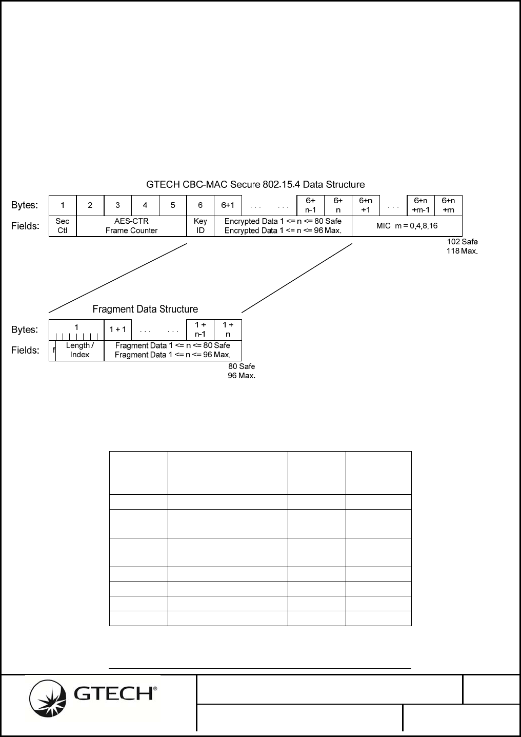
The entire GTECH485 data packet will be encrypted and encapsulated into the data payload section of
the secure 802.15.4 packet. Using CCM* security and AES-128 bit key, the maximum safe data length
for a single 802.15.4 packet ~80 bytes. The entire packet up to 80 bytes is encrypted/decrypted using
the 802.15.4 standard security functions. Using the 802.15.4 Short Addressing option, additional bytes
may become available for user data.
TIMAC and the 802.15.4 standard do not directly support fragmentation of message streams of more
than 80-bytes (secure packet). A higher-level network layer is required to fragment/defragment large
messages. This may be performed by the Host CPU or the radio’s application layer. Fragmentation
requires additional overhead with each 802.15.4 packet that will reduce the maximum packet payload
length.
1234567 7+
n+1 7+
n+2
Flags Seq. Short
Dest. Addr. Short
Src. Addr. MAC Safe Payload 1 <= n <= 102
MAC Max Payload 1 <= n <= 118 CRC-16
7+
n
7+1 7+
n-1
. . . . . .
GTECH Unencrypted 802.15.4 MAC Packet Structure
Bytes:
Fields:
12345
AES-CTR
Frame Counter Encrypted Data 1 <= n <= 80 Safe
Encrypted Data 1 <= n <= 96 Max.
Sec
Ctl
6+n
+m
6+n
+1 . . .
GTECH CBC-MAC Secure 802.15.4 Data Structure
Bytes:
Fields:
111 Safe
127 Max.
102 Safe
118 Max.
MIC m = 0,4,8,16
6+1 6+
n-1 6+
n
. . .
123456
Preamble SFD PHR
Len. PHY Payload 9 <= n <= 127 (aMaxPHYPacketSize)
6+
n
6+1 6+
n-1
. . . . . .
2.4GHz 802.15.4 PHY Packet Structure (PPDU)
Bytes:
Fields:
. . .
. . . . . . . . . . . .
6+n
+m-1
. . .
Key
ID
6
Figure 13 - Packet Encapsulation
5.3 Acknowledgement
The 802.15.4 MAC layer acknowledges MAC packets and attempts retries when an acknowledge fails
to be received.
The GTECH485 protocol acknowledges are encrypted and encapsulated into the MAC payload just as
data above, using CCM* security and AES-128 bit key.
No. 96-1886-01E Rev.
1.1
GTECH Aircon Radio (Model GWT154)
PAGE 28 OF 72
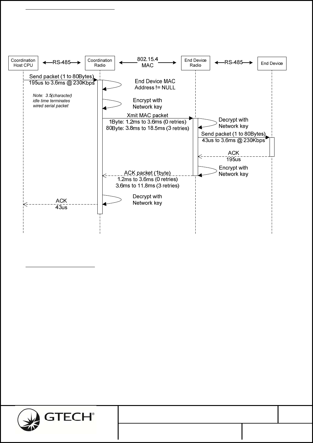
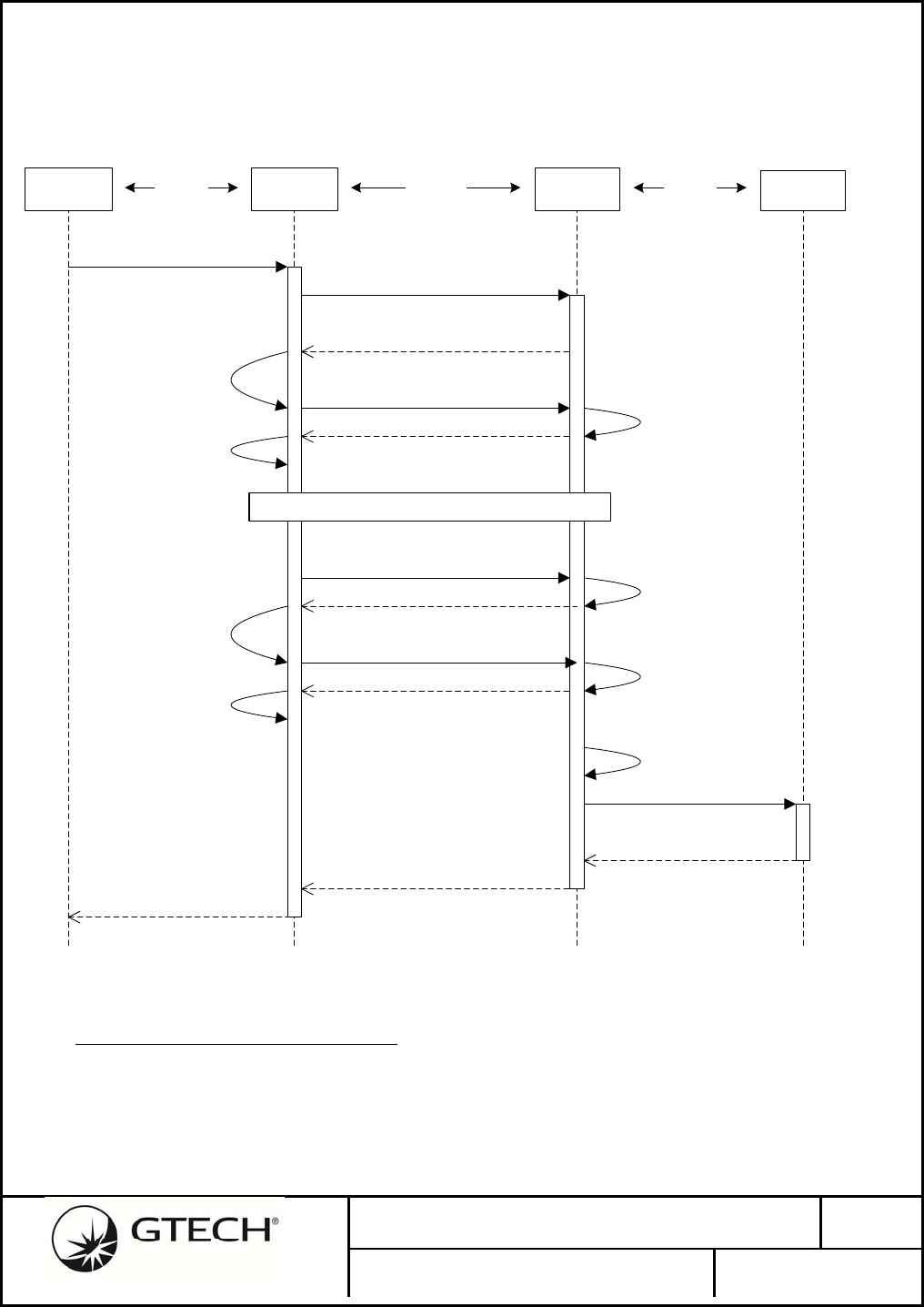
5.4 SingleUnicastMACPacket
GTECH485 packets less than the maximum 802.15.4 payload capacity are encapsulated in a single
MAC packet. The currently selected End Device address in the Access Control List is the packet’s
destination.
Figure 14 - Single MAC Packet Exchange
5.5 FragmentedPackets
Host CPU packets greater than the maximum 802.15.4 payload capacity, it must be subdivided into
smaller fragments. Fragmentation may be performed by either the Host CPU or the Radio module.
The following fragmentation is for the proposed Radio module method.
Serial data from the Host CPU to the Coordinator radio is buffered until the entire packet (up to 544-
bytes) is received, before beginning the RF transfer. The radio does not begin the RF transfer as soon
after 80 (or more) bytes have been received via the serial port as this would add complexity to the
sequence if the transfer were to be truncated, or in error. By increasing the Host interface serial data
rate to 230.4Kbps results in the serial latency being a relatively small percentage of the over-all packet
transmission time.
The End Device radio reassembles fragments into a buffer until the entire packet has been received,
before sending it to the peripheral.
Fragments must be sent and received in sequence; a fragment received out of sequence implies a lost
No. 96-1886-01E Rev.
1.1
GTECH Aircon Radio (Model GWT154)
PAGE 29 OF 72
fragment, and the entire packet is discarded. To minimize the radio’s overhead, it does not issue a
Negative Acknowledge (NAK) to the Host CPU, nor does it perform any clean-up of the un-sent
packet fragments. The Host CPU needs to implement a failsafe timeout. After a packet timeout, the
Host CPU may send a new packet to the Coordinator radio, overwriting the serial buffer and triggering
a new RF transmission.
Coordination
Host CPU Coordination
Radio
Send packet (549Bytes)
24.0ms @ 230kbps
End Device
End Device
Radio
Send packet (1 to 549Bytes)
43.4us to 23.8ms @ 230Kbps
ACK
43.4us
Xmit MAC packet (80Bytes)
3.8ms to 18.5ms (up to 3 retries)
RS-485 RS-485
802.15.4
MAC
length – bytes sent
Xmit ACK (1Byte)
1.2ms to 10.8ms (up to 3 retries)
length + bytes received
ACK
43.4us
Xmit ACK (1Byte)
1.2ms to 10.8ms (up to 3 retries)
length + bytes received
Note: Failure to receive any
ACK suspends further MAC
packet transmissions,
requiring timeout
termination
length + bytes received
length + bytes received
<= 80Bytes (last fragment)
length – bytes sent
< 80Bytes remain
Length = 0
Repeat as Neccessary
Note: 3.5(character)
idle time terminates
wired serial packet
Figure 15 - Data Fragmentation Sequence
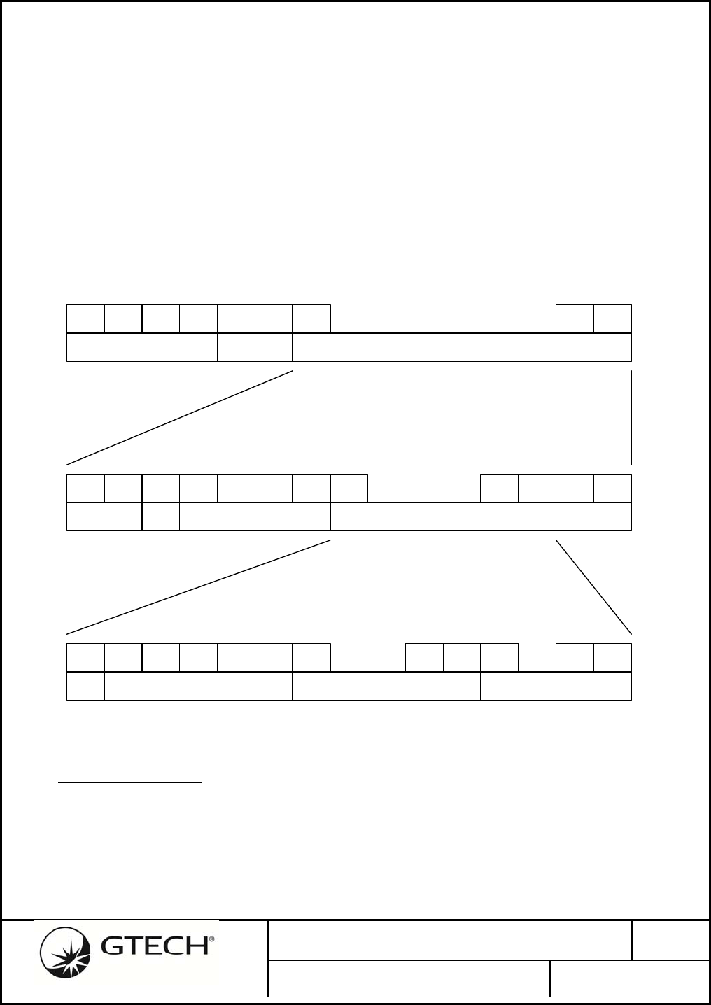
5.6 FragmentationPacketStructure
One byte in the secure 802.15.4 packet payload is allocated for the fragmentation header, leaving a
minimum of 80 user data bytes. The Length/Index field in the fragmentation header has two functions
depending on the state of the fragmentation flag bit. Host CPU serial packets requiring just one RF
packet clear the fragmentation flag and the remaining 7-bit files is the absolute byte-count of the
payload up to the maximum safe 802.15.4 encrypted packets payload size.
No. 96-1886-01E Rev.
1.1
GTECH Aircon Radio (Model GWT154)
PAGE 30 OF 72
Fragmented packets have the fragmentation flag set and are sequenced using a range of index values
above the maximum byte count of the secure 802.15.4 packet. An indexed fragment is assumed to
hold the maximum number of payload bytes. The exception being the end packet in a fragment
sequence where the fragmentation flag is set, but the Index/Length field contains a valid byte count for
the remaining bytes of the packet.
The maximum safe payload is derived from packets using extended addresses and PANs. Networks
using short addressing have the option of reallocating the unused extended address bytes to the payload
field. The fragmentation process described here uses the maximum safe payload length for its
calculations. If a larger encrypted payload length is employed, the calculations need to be adjusted
accordingly.
Figure 16 - Data Fragment Structure
Fragment
Flag (f) Length /
Index Fragment
Index Fragment
Length (n)
0 Length = 0
Radio Configuration
Packet
- -
0 1 <= Length <= 80 - n = Length
0 81 <= Length <= 111
reserved - n = Length
0 112 <= Length <=127
illegal - -
1 112 (0x70) 0 n = 80
1 113 (0x71) 1 n = 80
1 114 (0x72) 2 n = 80
1 115 (0x73) 3 n = 80
.
.
.
.
.
.
.
.
.

No. 96-1886-01E Rev.
1.1
GTECH Aircon Radio (Model GWT154)
PAGE 31 OF 72
1 125 (0x7D) 13 n = 80
1 126 (0x7E) 14 n = 80
1 127 (0x7F) 15 n = 80
1 1 <= Length <= 80 END n = Length
Table 12 - Fragmentation Codes

No. 96-1886-01E Rev.
1.1
GTECH Aircon Radio (Model GWT154)
PAGE 32 OF 72
6.0 WIRELESS INTER-COMMUNICATION
Configuration parameters for the End Device radios must be exchanged with the Coordinator radio, but
not conflict with the encapsulated GTECH485 protocol packets. A reserved protocol character in the
range between 0x0F and 0x1B could be used to indicate the start of a dedicated radio command packet.
This protocol character would need to be reserved for radio configuration packets in all future versions
of the GTECH485 protocol.
A more transparent method is to exploit the zero-length fragment shown in Table 12 - Fragmentation
Codes above. By definition, all radio configuration packets include a byte length as part of the header.
A radio configuration packet’s checksum may be calculated and verified without knowing the received
802.14.5 packet’s absolute payload length.
No. 96-1886-01E Rev.
1.1
GTECH Aircon Radio (Model GWT154)
PAGE 33 OF 72
7.0 HOST AND PERIPHERAL WIRED INTERFACES
7.1 WiredInter‐communication
7.1.1 HostProtocolEndianness
Both 802.15.4 and the CC2530’s 8051 processor core are native little-endian. 16 (2-byte), 32 (4-byte)
and above integers communicated serially between the Host and Coordinator radio will be sent Least
Significant Byte (LSB) first.
Bytes: 1 2 3 4 5 6 7
Words: 0x01 0x1234 0x0A0B0C0D
Serial: 0x01 0x34 0x12 0x0D 0x0C 0x0B 0x0A
Structure 1: Host Serial Interface Endian
Bytes are transmitted serially from left to right beginning with byte 1.
7.1.2 GTECHProtocolControlCharacters
The following table lists the special character codes used by the GTECH485 protocol to identify
message type and length. The Protocol characters in grey are reserved for exclusive use by the
GTECH485 protocol.
Type
Code Name Data Length Description
0x00 NUL Unused
0x01 SOH Unused
0x02 STX Unused
0x03 ETX Unused
0x04 EOT 0 End of Packet
0x05 ENQ variable Start of Data Packet
0x06 ACK 0 Packet Acknowledge
0x07 BEL Unused
0x08 BS Unused
0x09 HT Unused
0x0A LF Unused
0x0B VT Unused
0x0C FF Unused
0x0D CR Unused
0x0E SO Unused
0x0F SI Reserved: Legacy Exception
0x10 DLE Reserved
0x11 DC1/XON Reserved
0x12 DC2 Reserved
0x13 DC3/XOFF Reserved
0x14 DC4 Reserved
No. 96-1886-01E Rev.
1.1
GTECH Aircon Radio (Model GWT154)
PAGE 34 OF 72
0x15 NAK 0 Packet Negative Acknowledge
0x16 SYN 1 Set Peripheral Address / return
Status
0x17 ETB Reserved
0x18 CAN 0 Abort packet request
0x19 EM Reserved
0x1A SUB Reserved
0x1B ESC 1 Exception prefix
0x1C FS Unused
0x1D GS Unused
0x1E RS Unused
0x1F US Unused
Table 13 - GTECH Packet Type Codes
7.1.3 GTECHAddressPacket
The GTECH485 protocol uses query/response method to address individual Peripherals in a multi-drop
wired network. The Terminal issues a specific address command to select the active Peripheral, all
other Peripherals are to un-assert themselves from the bus. A reserved SYN (0x16) protocol character
is used to identify an address command packet.
Peripheral addresses are limited to a range between 0x21 and 0xFF. By default, if a peripheral
receives an address packet with an address other than its own, it is to un-assert itself from the bus.
The 802.15.4 radio module will need to parse the Host CPU interface serial stream for the GTECH485
protocol SYN character to properly route packets received from the Host CPU.
Bytes: 1 1
Fields: 0x16
SYN 0x21 <= a <= 0xff
Peripheral Address (a)
Structure 2: GTECH Address Packet
A peripheral addressed by an Address Packet is to reply with a response. The first byte is the repeated
address value. The second byte is a bit-mapped status byte. The radio module is required to send a
Response Packet when it is the addressed peripheral. At this time the Status will always be 0x00.
Note: Because the GTECH485 bus is a 4-wire bus, the radio does not receive another peripheral’s
Response Packet.
Bytes: 1 1
Fields: 0x21 <= a <= 0xff
Peripheral Address (a) Address Status
Structure 3: GTECH Address Response Packet
No. 96-1886-01E Rev.
1.1
GTECH Aircon Radio (Model GWT154)
PAGE 35 OF 72
Bits: 7 6 5 4 3 2 1 0
Field: Fault Reset Busy Req ? Req 3 Req 2 Req 1 Req 0
Structure 4: GTECH Protocol Address Status
Refer to [2] for bit field assignments in Address Response Status byte.
A special Un-Listen address (0x16) in the restricted range may be issued by the Host CPU to force all
peripherals off-line. It is assumed the Un-Listen address does not receive an Address Response from
any peripheral.
The radio module should interpret Un-Listen as any address other than its own and forward it to the
End Device radios. Packets receive from the Host CPU, after the Un-Listen address has been issued,
should be discarded until another valid Peripheral address packet is received from the Host CPU and
acknowledged by an End Device.
The End Device radio will be required to act as a Terminal proxy whenever it receives a SYN address
packet from the Coordinator. The End Device radio outputs the SYN packet on its local wired 485
bus, and then triggers a response acceptance period timer. Typically, a two-byte packet should be
received by the End Device radio’s 485 bus with the first byte equaling the prior SYN packet’s address
value. A successful response message is encapsulated in an RF packet and returned to the Coordinator
radio. In the event of a timeout, or invalid response message, no RF response is issued. The Terminal
Host CPU is expected to provide its own failsafe timeout.
Bytes: 1 1
Fields: 0x16
SYN 0x16
Un-Listen
Structure 5: GTECH Un-Listen Address Packet
An optional Extended Address (0x1C) is defined by the GTECH485 protocol. This feature will not be
supported by the radio firmware at this time.
Bytes: 1 1 1
Fields: 0x16
SYN 0x1C
Extend 0x21 <= a <= 0xff
Extended Address (a)
Structure 6: GTECH Address Response Packet
7.1.4 GTECHDataPacket
The GTECH485 protocol does not employ a length parameter; detection of the reserved EOT (0x04)
byte denotes the end of a data packet. The peripheral may detect the EOT to determine when it has
received a complete message from the Host CPU, but will be required to implement a secondary
failsafe timeout in the event the termination character is missed or corrupted. An idle period of more
than 3.5 characters, since receiving the last character, will be inferred by the radio module to also
indicate termination of a Host packet.
The maximum payload length specified for a single GTECH485 Data Packet is 544 characters. This
does not include header bytes, but includes any exception character insertions that have taken place.
No. 96-1886-01E Rev.
1.1
GTECH Aircon Radio (Model GWT154)
PAGE 36 OF 72
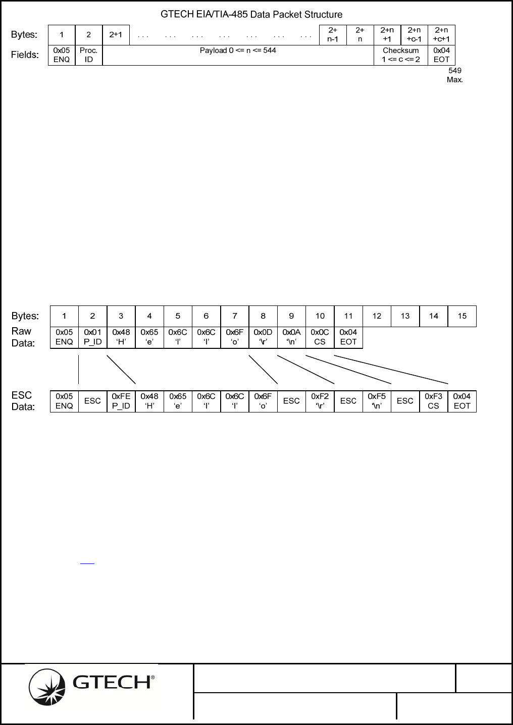
Figure 17 - GTECH Data Packet Structure
7.1.5 DataExceptionHandling
Special handling is required for binary data with values between 0x04 to 0x06 and 0x0F to 0x1B
because these ranges are reserved for GTECH485 protocol control characters. The control character
ESC (0x1B) is used as an escape prefix to signal that the following byte was in the range of the control
characters and has been modified (1’s complemented) to place it outside the reserved range. All
characters following the ESC are expected be in the range of 0x21 to 0xFF. In the event an ESC is
followed by a reserved protocol character, special exception handling is required.
The following example illustrates ESC insertion on a data packet with the string “Hello” as its payload.
Process-ID, Carriage-Return, Line-Feed and Checksum characters all fall in the reserved range; they
are 1’s complemented and prefixed with ESC before being transmitted. Other than being
complemented as necessary, the Checksum is unchanged from the value calculated on the raw data.
Figure 18 - Escape Character Insertion
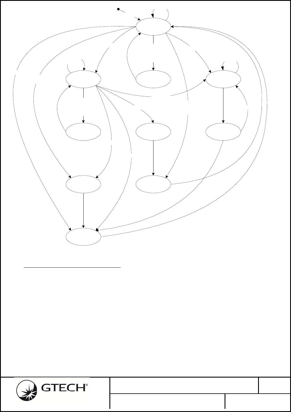
Referring to Error! Reference source not found., the UART receive process is reset to the idle state.
The protocol characters ACK, NAK, CAN and SI are encapsulated and unicast to the currently
connected radio. The protocol character SYN must be intercepted by the Coordinator radio to initiate a
new peripheral address selection sequence. The Coordinator radio will clear any current connection’s
address and broadcast the SYN address packet to all radios.
Anytime the ESC protocol character is received on the 485 bus, the exception state is entered.
Generally, the byte following ESC only needs to be inverted to restore it to its original value. It is
documented in [2], the GTECH485 Bus Packet Protocol Specification, how a peripheral receiver is to
respond in the event a protocol character does follow the ESC. ACK, NAC, CAN and SI are to be
processes as if the ESC had not occurred, though the byte immediately following is to be inverted. A
SYN address change will be processed normally, but any data received and buffered prior to that is
discarded. Start of a new data packet ENQ discards any previously buffered data and starts over. The
end of data packet EOT forwards the data packet to the connected radio, or processes locally if this
radio is the selected peripheral.
No. 96-1886-01E Rev.
1.1
GTECH Aircon Radio (Model GWT154)
PAGE 37 OF 72
Receive
Idle
Address
Reset
ESC(0x1B)
Exception
SYN(0x16)
FIFO empty |
ESC(0x1B) FIFO empty
FIFO empty &RxBuffer == 0
ENQ(0x05)
ACK(0x06) |
SI(0x0F) |
NAK(0x15) |
CAN(0x18) |
ENQ(0x05)
Process
Protocol
Reset
RxBuffer
1's Complement
Write to
RxBuffer
Process
Data Packet
In RxBuffer
EOT(0x04) |
RxBuffer != 0 &timeout
EOT(0x04)
Process
Peripheral
Address
0xE3 to 0xFF
SYN(0x16)
ACK(0x06) |
SI(0x0F) |
NAK(0x15) |
CAN(0x18) |
0x1C
Process
Protocol
0x00 to 0x03 |
0x07 to 0x0E |
0x1C to 0xFF
Figure 19 - Escape Sequencing State Machine
7.2 WiredInterfaceInfrastructure
7.2.1 RadioSet‐upandConfiguration
The Coordinator radio is controlled by the Host CPU by encapsulating configuration messages in a
GTECH485 protocol data packet. Radio configuration packets must implement the GTECH485
exception protocol so not to be misinterpreted by any other legacy GTECH peripherals that share the
same wired 485 bus as the Coordinator radio.
7.2.1.1 Persistent Configuration Parameters
Once set, certain configuration parameters must return to their configured values after a power-on-reset
or software reset event. Non-volatile memory is reserved on the CC2530’s Flash EEPROM to store
images of the configuration settings.
No. 96-1886-01E Rev.
1.1
GTECH Aircon Radio (Model GWT154)
PAGE 38 OF 72
Persistent Configuration Parameters
Command
Code Description
Mode Coordinator / End Device
PAN ID Short and Extended PAN ID
Address Short & Extended (EUI-64)
Set Channels - Default Coordinator only
Set Channels - Mask Channels End Device scans
Set RF - Tx Power Default Transmit Power
Set RF - Antenna Chip / External
Set RF - Failsafe End Device only
Peripheral Address Firewall Address filtering mask
Table 14 - Persistent Settings
7.2.1.2 Configuration Packet Structure Format
The radio configuration packet consists of a Command Code and Length, followed by variable number
of Parameter bytes. The packet is terminated with a Checksum that the sum of the Command Code,
Length and Parameter fields.
Bytes 1 1 0-255 1
Field Command Length Parameters Check
sum
Structure 7: Coordinator Command Packet
The Host CPU to Radio interface employs a query/response protocol where the Host CPU must always
poll for parameters from the Radio; the Radio never spontaneously transmits a packet over the Host
serial interface. The Radio should reply to all Host CPU data packets when it is the addressed
peripheral.
By definition, all Host CPU configuration packets requesting Parameters from the Radio are assigned
even Command Code values (the Least Significant Bit (LSB) is cleared). Host CPU configuration
packets writing Parameters to the Radio all have odd values (the LSB is set).
Host CPU write configuration packets should receive a reply packet from the Radio with the same
Command Code, zero Length and the Acknowledge bit set to one(1) if the Parameters were set as
instructed, or zero(0) if something failed.
Host CPU’s read configuration packets are sent to the Radio with zero Length. The Radio is to reply
with the same Command Code, the correct Parameter Length and the Acknowledge bit set to one(1) if
the requested parameters are in the Parameter field. If the requested parameters are not available, the
Radio should reply with the same Command Code with the Acknowledge bit set to zero(0) and zero
Length.
Command packets with failed checksums, unknown Command codes, or of incorrect Length, will be
ignored. The radio will not respond to failed command packets.

No. 96-1886-01E Rev.
1.1
GTECH Aircon Radio (Model GWT154)
PAGE 39 OF 72
The Host CPU must implement a fail-safe timeout in the event it does not receive a response from the
Radio.
Bits: 7 6 5 4 3 2 1 0
Field: Ack. Res. Code
Command Dir
Structure 8: Coordinator Command Byte
Bit 7: Acknowledge, command packets sent from the Host CPU to the Radio should
always set the Acknowledge bit to zero(0).
The Radio is to respond to all configuration writes (odd code values) with either Acknowledge set
to one(1) indicating success, or zero(0), if the Parameter(s) failed to be set as requested or the
action failed.
The Radio is to reply to all configuration reads (even code values) with either Acknowledge set to
one(1) indicating valid Parameters in the Parameter field, or zero(0) indicating the Parameter field
is invalid. Note: a zero(0) Acknowledge may be normal for a Parameter request like Join Request.
Bit 6: Reserved, should be set to zero(0).
Bits 5 to 1: Radio configuration commands, see Error! Reference source not found.
below.
Bit 0: Direction, when zero(0) the command packet is requesting Parameters from the
Radio be sent to the Host CPU. When one(1) the command packet is writing Parameters from the
Host CPU to the Radio.
Code Name Length Parameters Description
0x00 Status 18 Status Gets current radio configuration and status
parameters
0x01 Mode 1 Mode Initializes and configures the radio’s operating
modes
0x02 Get
Channels 5 Bit mask Retrieve the current 802.15.4 Channel Mask.
0x03 Set
Channels 5 Bit mask Set the 802.15.4 Channel mask and default
Channel.
0x04 Get
PAN-ID 2 ID Get Coordinator’s PAN ID
0x05 Set
PAN-ID 2 ID Set Coordinator’s PAN ID
0x06 Get Energy Scan 16 RSSI per
Channel Radio’s reply to energy scan of all Channels
of the 2.4GHz 802.15.4 band
0x07 Set Energy Scan 0 0 Start energy scan on all 802.15.4 Channels.
0x08 Get PAN Scan Variable PAN
Coordinators List of PAN Descriptors retrieved from Active
scan.

No. 96-1886-01E Rev.
1.1
GTECH Aircon Radio (Model GWT154)
PAGE 40 OF 72
Code Name Length Parameters Description
0x09 Set PAN Scan 0 0 Start Active scan for PAN Coordinators
0x0A Get
Device List Variable Address
List Gets Associated End Devices list
EUI-64 and Short Address.
0x0B Join PAN 10/26 Address
Network key Short & EUI-64 address of End Device to join
to PAN (RF packet includes network key).
0x0C Get
ACL Variable Access Control
List Get list of End Devices joined to this PAN
Coordinator radio.
0x0D Delete
ACL 10 Address Removes a single End Device from the
Access Control List
0x0F Set End Device 1/2/8 Address Select End Device radio using either
SYN(1), Short Address(2) or EUI-64(8)
0x11 Set
BAUD 2 BAUD Sets the EIA485 BAUD rate for the currently
selected End Device
0x12 Get
RF Config. 3 Tx power(dBm)
Antenna Sel. Gets the transmit power setting & antenna for
the currently selected End Device
0x13 Set
RF Config. 3 Tx power(dBm)
Antenna Sel. Sets the transmit power & antenna for the
currently selected End Device
0x14 Get Periph
Addr Mask 32 Bit-mapped
address mask Gets the current Peripheral address filtering
mask contents
0x15 Set Periph Addr
Mask 32 Bit-mapped
address mask Sets the Peripheral address filtering mask
0x16
Reserved
0x17
Reserved
0x18 Get Ping
Response 10 Addresses Reply with the address of End Device
responding to a Ping request.
0x19 Send
Ping 2/8 Address Send Ping to End Device radio using either
Short Address(2) or EUI-64(8)
0x1A Get RF
Registers Variable CC2530 RF
configuration Reply with current CC2530 radio
configuration register settings
0x1B Set RF Registers Variable CC2530 RF
configuration Sets select CC2530 radio configuration
registers with compliance test parameters
0x1C Get
LoopBack Variable PER Packet Error Test Results
0x1D Set
Loopback 1 Mode Selects diagnostic loopback test mode
0x1E Get
Version Variable ASCII string Firmware version in the format:
YYYY_MM_DD
0x1F Reset /
Break 1 Target Force all End Devices to Reset and assert a
Break condition on their 485 bus.
Table 15 - Coordinator Radio Command Codes

No. 96-1886-01E Rev.
1.1
GTECH Aircon Radio (Model GWT154)
PAGE 41 OF 72
7.2.2 RadioConfigurationPacketStructures
7.2.2.1 Status 0x00 (Radio to Host)
This configuration command causes the radio to respond with its current operating state and network
parameters.
Bytes: 1 1 1 1 2 2 8 4
Field: 0x00
Code 18
Length State Channel PAN-ID Short
Addr EUI-64 Up Time
Structure 9: Coordinator Status Packet
State: 0x00 Uninitialized.
0x01 End Device, idle.
0x02 End Device, attempting to join a PAN
0x03 End Device, associated with a PAN (not joined).
0x04 End Device, joined with PAN and active.
0x05 End Device, attempting to re-join PAN.
0x20 Coordinator, network idle.
0x21 Coordinator, network started.
0x22 Coordinator, network joining, is accepting new End Devices.
0x23 to 0x7F Reserved.
0x80 Test Mode, compliance testing state.
0x81 to 0xFF Reserved.
Channel: Current 2.4GHz 802.15.4 network channel assignment.
PAN-ID: Currently assigned network Private Area Network ID.
Short Addr: Short (16-bit) address assigned by PAN during joining.
EUI-64: Local radio’s Extended Unique Identifier (MAC address) permanently set at factory.
Up Time: Seconds elapsed since Power-On/Reset event. Rollover occurs in about 136-years.
7.2.2.2 Mode 0x01 (Host to Radio)
This configuration command defines the basic operating modes of the radio and provide low-level
network control functions.

No. 96-1886-01E Rev.
1.1
GTECH Aircon Radio (Model GWT154)
PAGE 42 OF 72
Bytes: 1 1 1
Field: 0x01
Code 1
Length Mode
Structure 10: Coordinator Initialize Packet
Mode: 0x00 Null. No operation.
0x01 to 0x0F Reserved.
0x10 Select un-configured. Neither a Coordinator nor End-Device radio.
0x11 Selects Coordinator radio mode.
0x12 Selects End-Device radio mode.
0x13 to 0x1F Reserved.
0x20 Start Network. If Coordinator mode selected, start the PAN.
0x21 Stop Network. If Coordinator mode, disable the PAN.
0x22 to 0x2F, Reserved.
0x30 Stop Joining. If Coordinator mode, stop responding to any new associate
requests. If End-Device, stop requesting to join a PAN.
0x31 Enable Joining. If Coordinator mode, respond to associate requests from
End-Device radios.
0x32 Request Joining. If End-Device, begin issuing periodic associate
requests to known PANs.
0x33 to 0x3f Reserved.
0x40 Save Non-volatile memory. Saves persistent radio configuration
parameters to Flash memory.
0x41 Erase Non-volatile memory. Restores radio configuration parameters in
Flash memory to factory default values.
0x42 to 0x7E Reserved.
0x7F Reset. If Coordinator, broadcasts reset message to radios in PAN.
7.2.2.3 Get Channel Mask (0x02)
Returns the current 802.15.4 / 2.4GHz Channel Mask bit settings.
Bytes: 1 1 4 1
Field: 0x02
Code 5
Length Channel
Mask Default
Channel
Structure 11: Channel Mask Status Packet
Channel Mask: 2.4GHz 802.15.4 Channel Mask bit fields.
No. 96-1886-01E Rev.
1.1
GTECH Aircon Radio (Model GWT154)
PAGE 43 OF 72
Bits: 31 30 29 28 27 26 25 24
Channel: - - - 28 27 26 25 24
Bits: 23 22 21 20 19 18 17 16
Channel: 23 22 21 20 19 18 17 16
Bits: 15 14 13 12 11 10 9 8
Channel: 15 14 13 12 11 - - -
Bits: 7 6 5 4 3 2 1 0
Channel: - - - - - - - -
Structure 12: Channel Mask Bit Fields
Default Channel: Coordinator’s operating channel or End Device’s default.
7.2.2.4 Set Channel Mask (0x03)
The Channel Mask is used by the MAC when performing an initial scan for existing 802.15.4 radios in
its immediate vicinity. A Channel bit set to one(1) enables that channel to be scanned. Channel bits
set to zero(0) are skipped during the scan.
When powering-up or after a reset, the End Device will always scan the channels in the channel mask
for its associated coordinator. The Coordinator, when restarted, will use the Default Channel for its
operating channel.
Bytes: 1 1 4 1
Field: 0x03
Code 5
Length Channel
Mask Default
Channel
Structure 13: Channel Mask Selection Packet
Channel Mask: 802.15.4 / 2.4GHz Channel Mask bit fields, see Error! Reference source not
found..
Default: 0x07FFF800
Default Channel: Coordinator’s start-up channel.
7.2.2.5 Get PAN-ID (0x04)
GTECH 802.15.4 radios will employ short (16-bit) Personal Area Network IDs. Get PAN-ID return
the Coordinator radio’s PAN address.
0 1 2 3
0x00 0xF8 0x7F 0x00
No. 96-1886-01E Rev.
1.1
GTECH Aircon Radio (Model GWT154)
PAGE 44 OF 72
Bytes: 1 1 2
Field: 0x04
Code 2
Length PAN-ID
Structure 14: Current Personal Area Network ID Packet
PAN-ID: 0xFFFF Broadcast PAN, used when pairing.
0xFFFE to 0x0000 Assigned PAN ID for this radio.
7.2.2.6 Set PAN-ID (0x05)
The Coordinator radio will generate a short (16-bit) PAN-ID based on its factory assigned EUI-64
address. The Host CPU may use this configuration command to overwrite the default with another
PAN-ID.
Bytes: 1 1 2
Field: 0x05
Code 2
Length PAN-ID
Structure 15: Assign PAN ID Packet
PAN-ID: 0xFFFF Reserved for Broadcast PAN, do not use.
0xFFFE to 0x0000 Host CPU assigned PAN-ID.
Default: 0x0000.
7.2.2.7 Get Energy Scan (0x06)
Returns a list of Received Signal Strength Indication (RSSI) for all 802.15.4 / 2.4GHz channels found
by the radio.
When initially commissioning an 802.15.4 network every effort should be made to identify a clear
channel to assign the new network. Energy Scan will enable the radio receiver on each channel in an
attempt to detect any interfering signal sources. In the event an interferer is detected, that channel may
be disabled for use by this Coordinator by clearing its bit in the Channel Mask.
Returns Length = 0 if radio busy scanning. Length = 1 if Energy Scan failed.
Bytes: 1 1 1 1 1 … 1 1 1
Field: 0x06
Code 18
Length CH 11
RSSI CH 12
RSSI CH 13
RSSI … CH 26
RSSI CH 27
RSSI CH 28
RSSI
Structure 16: RSSI Scan Result
Length: 0 Busy scanning.
1 Energy Scan failed.
2 to 15 Undefined.
16 to 18 Channels scanned.
No. 96-1886-01E Rev.
1.1
GTECH Aircon Radio (Model GWT154)
PAGE 45 OF 72
19 to 255 Undefined.
RSSI: 0x80(-128) Minimum RSSI, channel likely unoccupied.
0x80(-127) to 0xFF(-1) Channel’s measured RSSI.
7.2.2.8 Set Energy Scan (0x07)
Initiates the Radio’s Received Signal Strength Indication (RSSI) energy scan sequence.
Bytes: 1 1
Field: 0x07
Code 0
Length
Structure 17: Initiate RSSI Scan Packet
No parameters.
7.2.2.9 Get PAN Scan (0x08)
Returns a list of PAN-Descriptor structures for every PAN Coordinator discovered during a scan of all
channels.
Energy scan may not detect adjacent 802.15.4 networks that are configured for beacon-less operation.
PAN scan broadcasts a beacon request on all enabled channels and generates a list of PAN-Descriptors
for every PAN Coordinator that responds. During network commissioning, the Host CPU can use the
PAN-Descriptor list to identify a suitable channel for the new PAN.
The format of the PAN-Descriptor structure is a subset of the full TIMAC descriptor.
Returns Acknowledge = zero(0) (NAK) in its Command Byte and Length = 0 if radio busy scanning.
Length = 1 indicates PAN scan completed, but no PAN Coordinators detected.
Bytes: 1 1 11 11 11 … 11
Field: 0x08
Code 0 to n
Length PAN1
Desc. PAN 2
Desc. PAN 3
Desc. … PAN n
Desc.
Structure 18: Network Scan Result list
Length: 0 Busy scanning.
1 PAN scan failed to locate a coordinator.
7n Seven bytes per PAN Descriptor.
Descriptor: PAN Descriptor Structure for each network beacon response.
Bytes: 2 2 1 1 1 TBD
Field: Address PAN-ID Channel Link
Quality Security
Fail Security
Parameters
Structure 19: PAN Descriptior
Address: Short (16-bit) address of beacon Coordinator.
No. 96-1886-01E Rev.
1.1
GTECH Aircon Radio (Model GWT154)
PAGE 46 OF 72
PAN-ID: Short (16-bit) PAN-ID for the received beacon’s network.
Channel: Channel number for beacon’s network.
Link Quality: 0x00 to 0xFF, relative quality of received beacon.
Security Fail: Boolean flag indicating security processing failed.
Security Parameters:Refer to 802.15.4 MAC API swra192 V1.5, Texas Instruments
7.2.2.10 Reserved (0x09)
Initiates the Radio’s PAN-ID scan sequence.
Bytes: 1 1
Field: 0x09
Code 0
Length
Structure 20: Initiate RSSI Scan Packet
No parameters.
7.2.2.11 Get Device List (0x0A)
Returns a list of EUI-64 and Short address structures for any End Devices that sent an Associate
Request while the Coordinator radio.
When the Coordinator is enabled to join new End Device to its network, and it receives Association
Requests from one or more devices, the following information is returned to the Host CPU.
If no End Devices have attempted to Associate, the Coordinator radio will return a Length = 0 in its
response.
The Coordinator radio will clear the list of End Device Association Requests list after it has sent the
response packet back to the Host CPU.
Bytes: 1 1 10 10 10 … 10
Field: 0x0A
Code 0 to 10n
Length End
Device 1 End
Device 2 End
Device 3 … End
Device n
Structure 21: Associating Devices Address list
End Device: End Device address structure with EUI-64 and Short addresses.
Bytes: 8 2
Field: EUI-64 Short
Address
Structure 22: End Device Address Structure
EUI-64: Extended Unique Identifier (MAC Address) for End Device.
No. 96-1886-01E Rev.
1.1
GTECH Aircon Radio (Model GWT154)
PAGE 47 OF 72
Short Address: Coordinator assigned 802.15.4 Short Address.
7.2.2.12 Join PAN (0x0B)
Joins a newly associated End Device to the Coordinator’s PAN.
Based on the results of the Device List generated by the Coordinator radio during a joining session, the
Host CPU may instruct the Coordinator radio to permanently register the new device in its Access
Control List (ACL). In addition, the Coordinator radio sends a secure message to the selected End
Device with the Coordinator’s randomly generated network key that the device is to use for all future
re-associations to this PAN.
Bytes: 1 1 2 8 16
Field: 0x0B
Code 10/28
Length Short
Address EUI-64 Network
Key
Structure 23: End Device Join Response Packet
Short Address: Coordinator assigned Short Address for the End Device as obtained from
the Get Device List response packet.
EUI-64: Extended Unique Identifier (MAC Address) for the End Device as
obtained from the Get Device List response packet.
Network Key: (Optional) only sent wirelessly from the Coordinator radio to the End
Device radio when the device has been joined to the PAN.
7.2.2.13 Get ACL (0x0C)
Returns the entire Access Control List of structures from the Coordinator radio. The ACL is updated
during network commissioning and saved in non-volatile memory.
Bytes: 1 1 11 … 11
Field: 0x0C
Code 0 to 11n
Length ACL 1
Struct. … ACL n
Struct.
Structure 24: Access Control list
ACL: Access Control Structure. An unused ACL structure will be filled with all ones,
or 0xFF bytes, the erased state of the non-volatile memory.
Bytes: 1 2 8
Field: Key Index Short
Address EUI-64
Structure 25: End Device Access Control Structure
Key Index: Auxiliary Security Header Key Index value for this ACL entry.
0x00 No AES encryption key assigned.
0x01 Factory AES key (requesting to join).
0x02 Network AES key (joined).

No. 96-1886-01E Rev.
1.1
GTECH Aircon Radio (Model GWT154)
PAGE 48 OF 72
0x03 to 0xFF Unassigned key indices.
Short Address: Short address of End Device registered in this ACL entry.
EUI-64: Extended address of End Device registered in this ACL entry.
7.2.2.14 Delete ACL (0x0D)
Removes a single End Device’s Access Control List entry from the Coordinator radio’s memory. A
deleted Access Control entry has all its fields filled with 0xFF bytes.
Bytes: 1 1 2 8
Field: 0x0D
Code 10
Length Short
Address EUI-64
Structure 26: Delete ACL Entry Command Packet (Extended Address)
Short Address: Short address for the Access Control List entry to be removed.
EUI-64: Extended Unique Identifier (MAC address) for the Access Control List entry to
be removed.
7.2.2.15 Get End Device (0x0E) (unimplemented)
Returns the EUI-64 and Short address of the currently selected End Device used to tunnel GTECH485
protocol messages between the Terminal and Peripheral on the selected radio.
Bytes: 1 1 2 8
Field: 0x0E
Code 10
Length Short
Address EUI-64
Structure 27: Get End Device Address Request Packet
EUI-64: Extended Unique Identifier (MAC address) for End Device.
Short Address: Short Address for selected End Device.
7.2.2.16 Set End Device (0x0F)
Selects the End Device radio connection for tunneling GTECH485 protocol messages. The Type field
contains the GTECH485 protocol code identifying the encapsulated message. This configuration
command is also overloaded to allowing either Short or Extended addresses also to be encapsulated.
Type set to 0(zero) identifies an address overloaded message, Short or Extended address length is
determined by the Length field.
Bytes: 1 1 1 n
Field: 0x0F
Code 1+n
Length Type GTECH
Address
Structure 28: Set End Device Address Request Packet (GTECH Address)

No. 96-1886-01E Rev.
1.1
GTECH Aircon Radio (Model GWT154)
PAGE 49 OF 72
Type: 0x00 Short or EUI-64 address (as determined by Length)
0x06 GTECH485 ACK
0x15 GTECH485 NAK
0x16 GTECH485 SYN
0x18 GTECH485 CAN
GTECH485 protocol ACK, NAK and CAN messages are tunneled from End Device to Coordinator
using the Type field.
GTECH Address: 802.15.4 encapsulated GTECH485 protocol SYN Address string
broadcast from the Coordinator to all End Devices in the PAN.
Presently only single-byte GTECH SYN addresses are supported though
longer Extend address strings may be handled by the command structure
in the future. SYN Response messages from End Devices to Coordinator
are also identified by the SYN type with the GTECH Address field
containing the Address and peripheral Status response bytes.
Bytes: 1 1 1 8
Field: 0x0F
Code 9
Length 0x00
Type EUI-64
Address
Structure 29: Set End Device Address Request Packet (Extended Address)
EUI-64 Address: Extended Unique Identifier (MAC address) for End Device.
Bytes: 1 1 1 2
Field: 0x0F
Code 3
Length 0x00
Type Short
Address
Structure 30: Set End Device Address Request Packet (Short Address)
Short Address: Short Address for End Device to Select.
7.2.2.17 Get BAUD (0x10) (unimplemented)
Returns the BAUD rate setting for the Coordinator, or the most recently selected End Device radio’s
EIA485 serial bus interface. BAUD and Device fields are unused when Get BAUD configuration is
issued, the Coordinator radio response fills them in response.
Bytes: 1 1 1 1
Field: 0x10
Code 2
Length Device BAUD
Structure 31: Get Current Device BAUD
Device 0x00 Currently selected End Device radio.
0x01 Coordinator radio.
0x02 to 0xff Reserved.

No. 96-1886-01E Rev.
1.1
GTECH Aircon Radio (Model GWT154)
PAGE 50 OF 72
BAUD: 0x00 230,400
0x01 115,200
0x02 57,600
0x03 38,400
0x04 19,200
0x05 9,600
0x06 4,800
0x07 2,400
0x08 1,200
0x09 600
0x0A 300
0x0B to 0xFF Unassigned.
Default: 0x04
7.2.2.18 Set BAUD (0x11)
Sets the BAUD rate setting for the Coordinator, or most recently selected End Device radio’s EIA485
serial bus interface.
Bytes: 1 1 1 1
Field: 0x11
Code 2
Length Device BAUD
Structure 32: Set Current Device BAUD
Device: 0x00 Currently selected End Device radio.
0x01 Coordinator radio.
0x02 to 0xFF Unused / Reserved.
BAUD: 0x00 230,400
0x01 115,200
0x02 76,800
0x03 38,400
0x04 19,200
0x05 9,600
0x06 4,800
0x07 2,400
0x08 1,200
0x09 600
0x0A 300
0x0B to 0xFF Unassigned.
7.2.2.19 Get RF Configuration (0x12)
Returns the signed 8-bit Transmit power setting and Antenna selection and Lost Coordinator Failsafe
time for the Coordinator, or most recently selected End Device’s radio. The Device field must be to
for the target device; the Transmit Power, Antenna and Failsafe fields are unused when Get RF is
issued, the Coordinator fills them in response.
Bytes: 1 1 1 1 1 1
No. 96-1886-01E Rev.
1.1
GTECH Aircon Radio (Model GWT154)
PAGE 51 OF 72
Field: 0x12
Code 4
Length Device Transmit
Power Antenna
Select Failsafe
Timeout
Structure 33: Get Current Device RF Configuration
Device 0x00 Reserved.
0x01 Coordinator radio.
0x02 to 0x20 Unused / Reserved.
0x21 to 0xff Currently selected End Device radio.
Transmit Power: -128 to -1 Illegal
0 to +19 Output power in dBm
+20 to +127 Illegal
Antenna Select: 0x00 Internal
0x01 External
Failsafe Time: 0 Lost Coordinator Failsafe inhibited.
1 to 99 Failsafe timeout period in seconds.
7.2.2.20 Set RF Configuration (0x13)
Sets the signed 8-bit Transmit power setting and Antenna select for the Coordinator, or currently
selected End Device radio.
Bytes: 1 1 1 1 1 1
Field: 0x13
Code 4
Length Device Transmit
Power Antenna
Select Failsafe
Time
Structure 34: Set Current Device Transmit Power
Device: 0x00 Currently selected End Device radio.
0x01 Coordinator radio.
0x02 to 0xFF Unused / Reserved.
Transmit Power: -128 to -1 Illegal
0 to +19 Output power in dBm
+20 to +127 Illegal
Transmit
Power dBm Power CC2530
Register
19 79 mW 0xD5
18 63 mW 0xC5
17 50 mW 0xB5
16 40 mW 0xA5
15 32 mW 0x95
14 0x95
13 20 mW 0x85
12 16 mW 0x75
11 0x75
10 10 mW 0x65
9 0x65
8 6.3 mW 0x55
7 0x55
No. 96-1886-01E Rev.
1.1
GTECH Aircon Radio (Model GWT154)
PAGE 52 OF 72
6 0x55
5 3.2 mW 0x45
4 0x45
3 2.0 mW 0x35
2 0x35
1 0x35
0 1.0 mW 0x25
Table 16 - Transmit Power Settings
Antenna Select: 0x00 Internal
0x01 External
Failsafe Time: 0 Lost Coordinator Failsafe inhibited.
1 to 255 Failsafe timeout period in seconds.
7.2.2.21 Get GTECH485 Peripheral Address Mask (0x14)
Returns the current Peripheral address filtering mask.
Bytes: 1 1 32
Field: 0x14
Code 0
Length Peripheral
Address Mask
Structure 35: Get Current Peripheral Address Mask
Peripheral Address mask: See Error! Reference source not found. below.
7.2.2.22 Set GTECH485 Peripheral Address Mask (0x15)
Sets the GTECH485 Peripheral address filter mask. The Coordinator radio will forward GTECH485
messages to End Devices with their corresponding mask bit set true(1) in the Peripheral Address Mask.
Attempts to select End Devices that are blocked by the filter (bit set to 0) disconnects the Coordinator
from any previously selected End Device radios. The mask structure consists of 32 8-bit bytes for a
total of 256 GTECH Peripheral addresses that are filtered.
Bytes: 1 1 32
Field: 0x15
Code 32
Length Peripheral
Address Mask
Structure 36: Set Current Peripheral Address Mask
Address Mask: One bit per GTECH485 Peripheral address. Setting a mask bit to 1
allows that Peripheral address to be accessed wirelessly. Setting a mask
bit to 0 inhibits over-the-air communication with Peripherals of that
address.
Offset Bits: 7 6 5 4 3 2 1 0
0 Address: 0x07 0x06 0x05 0x04 0x03 0x02 0x01 0x00
1 Address: 0x0F 0x0E 0x0D 0x0C 0x0B 0x0A 0x09 0x08
2 Address: 0x17 0x16 0x15 0x14 0x13 0x12 0x11 0x10
3 Address: 0x1F 0x1E 0x1D 0x1C 0x1B 0x1A 0x19 0x18
4 Address: 0x27 0x26 0x25 0x24 0x23 0x22 0x21 0x20
No. 96-1886-01E Rev.
1.1
GTECH Aircon Radio (Model GWT154)
PAGE 53 OF 72
5 Address: 0x2F 0x2E 0x2D 0x2C 0x2B 0x2A 0x29 0x28
6 Address: 0x37 0x36 0x35 0x34 0x33 0x32 0x31 0x30
7 Address: 0x3F 0x3E 0x3D 0x3C 0x3B 0x3A 0x39 0x38
8 Address: 0x47 0x46 0x45 0x44 0x43 0x42 0x41 0x40
9 Address: 0x4F 0x4E 0x4D 0x4C 0x4B 0x4A 0x49 0x48
10 Address: 0x57 0x56 0x55 0x54 0x53 0x52 0x51 0x50
11 Address: 0x5F 0x5E 0x5D 0x5C 0x5B 0x5A 0x59 0x58
12 Address: 0x67 0x66 0x65 0x64 0x63 0x62 0x61 0x60
13 Address: 0x6F 0x6E 0x6D 0x6C 0x6B 0x6A 0x69 0x68
14 Address: 0x77 0x76 0x75 0x74 0x73 0x72 0x71 0x70
15 Address: 0x7F 0x7E 0x7D 0x7C 0x7B 0x7A 0x79 0x78
16 Address: 0x87 0x86 0x85 0x84 0x83 0x82 0x81 0x80
17 Address: 0x8F 0x8E 0x8D 0x8C 0x8B 0x8A 0x89 0x88
18 Address: 0x97 0x96 0x95 0x94 0x93 0x92 0x91 0x90
19 Address: 0x9F 0x9E 0x9D 0x9C 0x9B 0x9A 0x99 0x98
20 Address: 0xA7 0xA6 0xA5 0xA4 0xA3 0xA2 0xA1 0xA0
21 Address: 0xAF 0xAE 0xAD 0xAC 0xAB 0xAA 0xA9 0xA8
22 Address: 0xB7 0xB6 0xB5 0xB4 0xB3 0xB2 0xB1 0xB0
23 Address: 0xBF 0xBE 0xBD 0xBC 0xBB 0xBA 0xB9 0xB8
24 Address: 0xC7 0xC6 0xC5 0xC4 0xC3 0xC2 0xC1 0xC0
25 Address: 0xCF 0xCE 0xCD 0xCC 0xCB 0xCA 0xC9 0xC8
26 Address: 0xD7 0xD6 0xD5 0xD4 0xD3 0xD2 0xD1 0xD0
27 Address: 0xDF 0xDE 0xDD 0xDC 0xDB 0xDA 0xD9 0xD8
28 Address: 0xE7 0xE6 0xE5 0xE4 0xE3 0xE2 0xE1 0xE0
29 Address: 0xEF 0xEE 0xED 0xEC 0xEB 0xEA 0xE9 0xE8
30 Address: 0xF7 0xF6 0xF5 0xF4 0xF3 0xF2 0xF1 0xF0
31 Address: 0xFF 0xFE 0xFD 0xFC 0xFB 0xFA 0xF9 0xF8
Structure 37: GTECH485 Peripheral Address Filter Mask
7.2.2.23 Reserved (0x16)
7.2.2.24 Reserved (0x17)
7.2.2.25 Get Ping (0x18)
Polls the Coordinator radio for any response to a Host CPU Send Ping. Replies with Length = zero(0)
if no Ping response has been received.
Bytes: 1 1 1 1 1

No. 96-1886-01E Rev.
1.1
GTECH Aircon Radio (Model GWT154)
PAGE 54 OF 72
Field: 0x18
Code 15 - 80
Length Coordinator
RSSI Coordinator
LQI End Device
RSSI
Bytes: 1 1 2 8 0 - 65
Field: End Device
LQI Transmit
Power Short
Address EUI-64 Test
Data
Structure 38: End Device Ping Response Packet
RSSI: Coordinator RSSI is the Receive Signal Strength Indication as received
by the pinged End Device radio. The End Device RSSI is the signal
strength of the ping response packet received by the Coordinator.
LQI: Link Quality Indication, like RSSI above, is the packet link quality of the
packet when received by the End Device and Coordinator.
Transmit Power: End Device’s transmit power index.
Short Address: Pinged End Device’s 16-bit address.
EUI-64: Extended Unique Identifier (MAC address) of End Device.
Test Data: Optional test patterns from Host CPU, End Device returns test data
image unchanged.
7.2.2.26 Send Ping (0x19)
Sends a wireless test packet to the addressed or selected End Device. If and End Device radio is not
selected, or fails to respond to the ping packet, an Acknowledge will not be returned to the Host CPU.
When a Send Ping configuration command is Acknowledged, the Host CPU may then issue a Get Ping
request to the Coordinator radio to obtain the Ping metrics.
Bytes: 1 1 1 1 1
Field: 0x19
Code 15 – 80
Length Coordinator
RSSI Coordinator
LQI End Device
RSSI
Bytes: 1 1 2 8 0 - 65
Field: End Device
LQI Transmit
Power Short
Address EUI-64 Test
Data
Structure 39: End Device Ping Request Packet
RSSI: Reserved for Ping response, Host CPU should fill with zero(0).
LQI: Reserved for Ping response, Host CPU should fill with zero(0).
Transmit Power: Reserved for Ping response, Host CPU should fill with zero() .
Short Address: 802.15.4 Short Address for End Device to Ping, setting to Broadcast 0xFFFF
(255, 255) will instead address the most recently selected GTECH Peripheral’s
End Device radio.
EUI-64: Reserved for Ping response, Host CPU should fill with zeros(0.0.0.0.0.0.0.0).
Test Data: Optional test patterns.
7.2.2.27 Get CC2530 RF Registers (0x1A)
Bytes: 1 1 n

No. 96-1886-01E Rev.
1.1
GTECH Aircon Radio (Model GWT154)
PAGE 55 OF 72
Field: 0x1A
Code n
Length CC2530 RF
Registers
Structure 40: CC2530 Get CC2530 RF Registers Packet
Registers: Array of current RF registers 8-bit register values.
7.2.2.28 Set CC2530 RF Registers (0x1B)
Bytes: 1 1 n
Field: 0x1B
Code n
Length CC2530 RF
Configuration
Structure 41: CC2530 Set CC2530 RF Registers Packet
Configuration: Array of RF registers values to be used by the radio.
7.2.2.29 Get Loopback Results (0x1C)
Bytes: 1 1 1 2 2
Field: 0x1C
Code n
Length Reserved Packets
Sent Packets
Received
Structure 42: Loopback Test Result Packet
7.2.2.30 Set Loopback Mode (0x1D)
Selects a loopback mode for diagnostic and compliance test purposes.
Bytes: 1 1 1
Field: 0x1D
Code 1
Length Mode
Structure 43: Set Loopback Packet
Mode: 0x00 Loopback tests disabled.
0x01 Start/Reset Packet Error Rate (PER) test.
0x02 Enable continuous packet transmit test.
0x03 to 0xFF Unassigned.
7.2.2.31 Get Version (0x1E)
Responds with current firmware version using a null-terminated ASCII string.
Bytes: 1 1 variable
Field: 0x1E
Code variable
Length Version
string
Structure 44: Get Version
Version: ASCII byte string in the format YYYY_MM_DDr(null) where:
YYYY 4-digit year i.e. 2000.
MM 2-digit month i.e. 04 (April).
DD 2-digit day.
r revision letter (a to z).
null 0 (‘/0’).

No. 96-1886-01E Rev.
1.1
GTECH Aircon Radio (Model GWT154)
PAGE 56 OF 72
7.2.2.32 Set Break (0x1F)
Simulates a Coordinator radio’s response to a hardware Break condition on its EIA485 interface.
The Coordinator radio will broadcast a configuration message to all End Devices in its PAN forcing
them perform a hardware Reset and assert a hardware Break condition on each End Device’s EIA485
serial bus as part of its startup sequence.
Bytes: 1 1 1
Field: 0x1F
Code 1
Length Target
Structure 45: Generate Reset / Break Sequence
Target: 0x00 Resets Terminal radio (coordinator).
0x01 Broadcasts Reset command to all End Devices.
0x02 to 0xFF Reserved
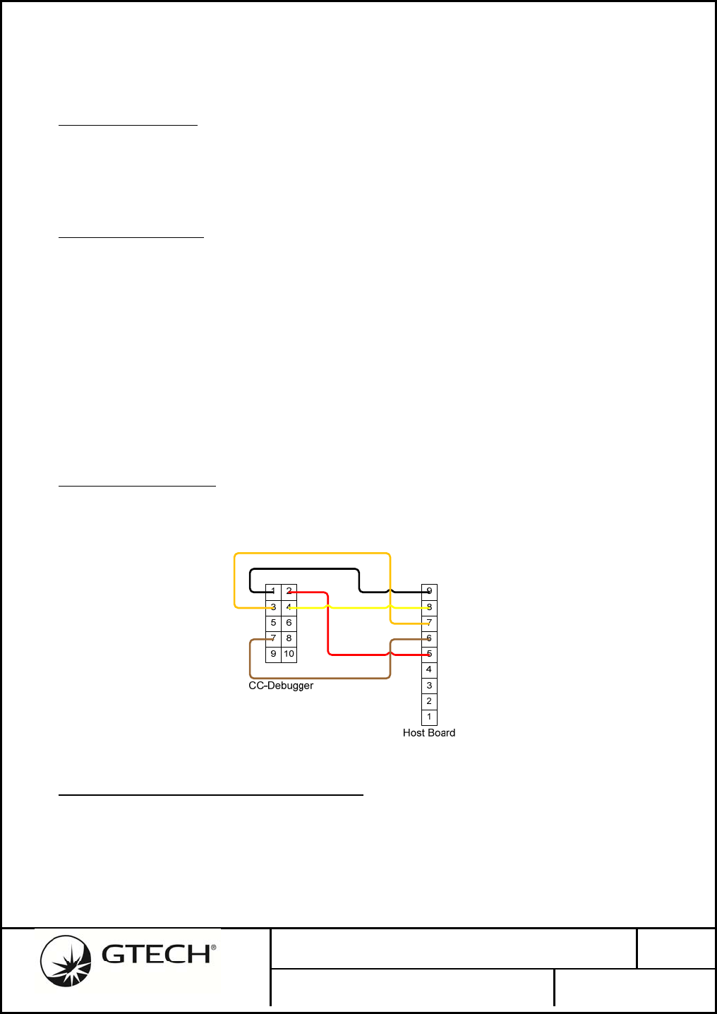
No. 96-1886-01E Rev.
1.1
GTECH Aircon Radio (Model GWT154)
PAGE 57 OF 72
8.0 USER INTERFACE
The basic GWT154 Radio Module has one user LED status indicator and one momentary contact
pushbutton switch input. The following radio modes are initiated and indicated by the following:
8.1 UninstalledRadio
An un-commissioned radio from the factory defaults as an End Device that has not been joined to a
PAN Coordinator. When initially powered the indicator LED may flash Red, then it will be
extinguished.
8.2 EndDeviceJoining
Pressing and holding the pushbutton switch on the radio for more than 3-seconds, but not more than
10-seconds will place the End Device radio into the network join mode. The radio will attempt to
Associate with any nearby PAN Coordinators and indicates this by flashing the LED at a 500ms ON
and 500ms OFF cadence.
If and when, while attempting to Associate, the radio receives a beacon from a Coordinator in response
to its beacon request, the LED will be steady ON indicating it has found a PAN Coordinator.
If, after 30-seconds, the End Device radio does not successfully negotiate joining a network, the radio
will abort the joining mode and turn the LED OFF.
8.3 RadioProgramming
The GWT154 Wireless Transceiver is programmed using Texas Instruments’ CC-Debugger in-system-
debugger/programmer for CC2530 and an adapter cable.
Figure 20 – Custom Adapter Cable
8.4 AlternateConfigurationandSetupTool
The GTECH485 Test Tool is a PC application developed for a Windows platform. This tool can be
used in manufacturing, compliance testing and by GTECH field engineers to configure and setup the
radios.
Specific information can be found in GTECH’s Field Service Training manuals. Which are available

No. 96-1886-01E Rev.
1.1
GTECH Aircon Radio (Model GWT154)
PAGE 58 OF 72
through GTECH Technical Training and Support Services, (401) 392-7961.

No. 96-1886-01E Rev.
1.1
GTECH Aircon Radio (Model GWT154)
PAGE 59 OF 72
9.0 HOST PORT CONFIGURATION SEQUENCES
9.1 CoordinatorConfiguration,NetworkStartandJoining
To configure a factory-new radio as a PAN Coordinator, start the network and enable acceptance of
new End Device radios requires the following steps. Though not necessary for configuration,
initialling requesting the radio’s status verifies communication has been successfully established and if
the radio is factory-new or has been previously configured.
Select Coordinator Radio as the current 485 Peripheral
Get Status
Perform RSSI energy scan
Once the RSSI scan has been initiated, the Terminal/Host must periodically poll the Coordinator for
the scan results. Note: unless the Terminal/Host addresses another Peripheral on its wired 485 bus, the
Coordinator’s Peripheral address only needs to be sent at the beginning of a configuration sequence.
Get RSSI results
After the Terminal/User has selected a suitable channel, the radio may be configured.
Set Mode to Coordinator
Set Channel Mask and Default Channel
Set Mode to Start Network
Set Mode to Enable Joining
Once the network has been started and is ready to accept new End Devices the Coordinator must be
periodically polled to detect End Device associations.
Get ACL
The Coordinator returns the entire contents of its Access Control List (ACL); this includes both new
association requests and previously joined devices. New requests will have their security Key Index
set to 1 (Factory Key used). The Terminal/Host may join a new End Device by responding to its
associate request.
Join PAN
The Coordinator radio will continue to accept new associated requests until the Terminal/Host disables
it. If new devices have been accepted to the PAN the Terminal/Host should also instruct the
Coordinator radio to save the updated ACL to persistent memory.
Set Stop Joining Mode
Set Mode to NV Save
Optionally, the Terminal/Host may obtain the radio’s firmware version.
No. 96-1886-01E Rev.
1.1
GTECH Aircon Radio (Model GWT154)
PAGE 60 OF 72
9.1.1 SelectPeripheralAddress,SetMode
Set Mode: Coordinator.
Message Terminal/Host Coordinator Radio
SYN-Address 16 01 01 00
Set Mode 05 00 01 01 1B EE ED 04 06
05 00 81 00 7F 04
9.1.2 SelectPeripheralAddress,GetStatus
Get Status: Coordinator Idle (0x20), Channel 17 (~0xEE), PAN ID 0xC05F, Short Address 0xC05F,
EUI-64 0.18.75.0.1.26.56.26, Up Time 0x000007E1.
Message Terminal/Host Coordinator Radio
SYN-Address 16 01 01 00
Get Status 05 00 00 00 00 04 06
05 00 80 1B ED 20 1B EE F5
C0 F5 C0 1B E5 38 1B E5 01
00 4B 1B ED 00 E1 07 00 00
21 04
9.1.3 SetPeripheralAddress,StartRSSIEnergyScan
Set energy scan:
Message Terminal/Host Coordinator Radio
SYN-Address 16 01 01 00
Set Energy
Scan
05 00 07 00 F9 04 06
05 00 87 00 79 04
9.1.4 SetPeripheralAddress,GetRSSIScanResult
The Terminal/Host polls the Coordinator Radio until it receive a non-zero length response. Channels
27 and 28 are blocked by the Channel Mask and return a 0xFF.
RSSI results: 36 (channel-11), 70, 61, 11, 0, 42, 89, 47, 0, 67, 92, 100, 75, 0, 0 (channel-26), 255, 255.
Message Terminal/Host Coordinator Radio
SYN-Address 16 01 01 00
Get Energy
Scan
05 00 1B F9 00 FA 04 06
05 00 86 00 7A 04
SYN-Address 16 01 01 00
Get Energy
Scan
05 00 1B F9 00 FA 04 06
05 00 86 00 7A 04
No. 96-1886-01E Rev.
1.1
GTECH Aircon Radio (Model GWT154)
PAGE 61 OF 72
SYN-Address 16 01 01 00
Get Energy
Scan
05 00 1B F9 00 FA 04 06
05 00 86 1B ED 24 46 3D 0B
00 2A 59 59 2F 00 43 5C 64
4B 00 00 FF FF 5F 04
9.1.5 SelectPeripheralAddress,SetChannelMaskandDefaultChannel
Set Channels: Channel Mask 0x07FFF800, Default Channel-11 (0x0B).
Message Terminal/Host Coordinator Radio
SYN-Address 16 01 01 00
Set Mode 05 00 03 1B FA 00 F8 FF
07 0B EF 04
06
05 00 83 00 7D 04
9.1.6 SetPeripheralAddress,SetStartNetworkMode
Set Mode: Start Network.
Message Terminal/Host Coordinator Radio
SYN-Address 16 01 01 00
Set Mode 05 00 01 01 20 DE 04 06
05 00 81 00 7F 04
9.1.7 SetPeripheralAddress,SetEnableJoiningMode
Set Mode: Enable Joining.
Message Terminal/Host Coordinator Radio
SYN-Address 16 01 01 00
Set Mode 05 00 01 01 31 CD 04 06
05 00 81 00 7F 04
9.1.8 SetPeripheralAddress,PollACL(nodevices)
Get ACL: returns zero-length response message
Message Terminal/Host Coordinator Radio
SYN-Address 16 01 01 00
Get ACL 05 00 0C 00 F4 04 06
05 00 8C 00 74 04
SYN-Address 16 01 01 00
Get ACL 05 00 0C 00 F4 04 06
05 00 8C 00 74 04
No. 96-1886-01E Rev.
1.1
GTECH Aircon Radio (Model GWT154)
PAGE 62 OF 72
9.1.9 PollACL(onedeviceassociated)
Get ACL: AES Key Index 1, Short Address 0x0001, EUI-64 0.18.75.0.1.26.56.37
Message Terminal/Host Coordinator Radio
SYN-Address 16 01 01 00
Get ACL 05 00 0C 00 F4 04 06
05 00 8C 0B 01 01 00 25 38 1B
E5 01 00 4B 1B ED 00 92 04
SYN-Address 16 01 01 00
Get ACL 05 00 0C 00 F4 04 06
05 00 8C 0B 01 01 00 25 38 1B
E5 01 00 4B 1B ED 00 92 04
9.1.10 SelectPeripheralAddress,JoinPAN
Using the Short Address and Extended Address (EUI) selected from the ACL, join an End Device to
the network.
Join PAN: Short Address 0x0001, EUI-64 0.18.75.0.1.26.56.37.
Message Terminal/Host Coordinator Radio
SYN-Address 16 01 01 00
Join PAN 05 00 0B 0A 01 00 25 38
1B E5 01 00 4B 1B ED 00
1B EA 04
06
05 00 8B 00 75 04
9.1.11 SelectPeripheralAddress,StopJoiningMode
Set Mode: Stop Joining.
Message Terminal/Host Coordinator Radio
SYN-Address 16 01 01 00
Set Mode 05 00 01 01 30 CE 04 06
05 00 81 00 7F 04
9.1.12 SelectPeripheralAddress,SetNVSaveMode
Set Mode: NV Save.
Message Terminal/Host Coordinator Radio
SYN-Address 16 01 01 00
Set Mode 05 00 01 01 40 BE 04 06
05 00 81 00 7F 04
9.1.13 SelectPeripheralAddress,GetRadioFirmwareVersion
Get Version: 2011_03_02b.
No. 96-1886-01E Rev.
1.1
GTECH Aircon Radio (Model GWT154)
PAGE 63 OF 72
Message Terminal Coordinator
SYN-Address 16 01 01 00
Get Version 05 00 1E 00 E2 04 06
05 00 9E 0C 32 30 31 31 5F
30 33 5F 30 32 62 00 AD 04
9.1.14 SelectPeripheralAddress,GetChannelMaskandDefaultChannel
Get Channel Mask: 0x7FFF800, Default Channel-11.
Message Terminal/Host Coordinator Radio
SYN-Address 16 01 01 00
Get
Channels
05 00 02 00 FE 04 06
05 00 82 1B FA 00 F8 FF 07
1B EE 6A 04
9.2 CoordinatorConfigurationSettingFirewallAddressMask
Before the Terminal/Host may address and communicate with an End Device Peripheral, it must write
the Coordinator’s Firewall Address Mask. The Mask may be optionally saved to persistent memory by
issuing the NV Save Mode.
Send Address Filter Mask
Get Address Filter Mask
Set NV Save Mode
9.2.1 SetPeripheralAddressFilteringMask,GetPeripheralAddressMask
Set Peripheral Address Mask: 0x21 through 0x2F enabled for wireless communication.
Get Peripheral Address Mask: Matches set mask above.
Set Mode: NV Save
Message Terminal/Host Coordinator Radio
SYN-Address 16 01 01 00
Set
Peripheral
Address Mask
05 00 1B EA 20 00 00 00 00
FE FF 00 00 00 00 00 00 00
00 00 00 00 00 00 00 00 00
00 00 00 00 00 00 00 00 00
00 CE 04
06
05 00 95 00 6B 04
Get
Peripheral
Address Mask
05 00 1B EB 00 EC 04 06

No. 96-1886-01E Rev.
1.1
GTECH Aircon Radio (Model GWT154)
PAGE 64 OF 72
05 00 94 20 00 00 00 00 FE FF
00 00 00 00 00 00 00 00 00 00
00 00 00 00 00 00 00 00 00 00
00 00 00 00 00 00 4F 04
Set Mode 05 00 01 01 40 BE 04 06
05 00 81 00 7F 04
9.3 CoordinatorConfiguration–GetEndDeviceStatistics
After a PAN has been created, and the network configuration parameters saved persistently in all
devices, the Terminal/Host may acquire wireless link signal strength and quality information from all
End Devices in the network. An End Device radio is selected by addressing the Peripheral wired to it.
Once selected, the Coordinator – End Device link is maintained until the Terminal/Host addresses a
different Peripheral.
Link quality and End Device 802.15.4 addressing may be obtained from the currently selected
Peripheral End Device using a Ping diagnostic message.
Select Peripheral address
Send Ping
Get Ping Response
9.3.1 SelectPeripheralAddress,SendPing
Send Ping: Coordinator RSSI 0, Coordinator LQI 0, End Device RSSI 0, End Device LQI 0, End
Device Transmit Power 0, End Device Short Address 0, End Device EUI-64 0.0.0.0.0.0.0.0, Test Data
0x30, 0x31 to 0x5F.
Get Ping: Coordinator RSSI 207, Coordinator LQI 89, End Device RSSI 223, End Device LQI 134,
Transmit Power 15, Short Address 0x0001, EUI-64 0.18.75.0.1.26.56.37, Test Data 0x30, 0x31 to
0x5F.
No. 96-1886-01E Rev.
1.1
GTECH Aircon Radio (Model GWT154)
PAGE 65 OF 72
Message Terminal/Host Coordinator Radio
SYN-Address 16 20 20 00
Send Ping 05 00 1B E6 41 00 00 00 00
00 FF FF 00 00 00 00 00 00
00 00 30 31 32 33 34 35 36
37 38 39 3A 3B 3C 3D 3E 3F
40 41 42 43 44 45 46 47 48
49 4A 4B 4C 4D 4E 4F 50 51
52 53 54 55 56 57 58 59 5A
5B 5C 5D 5E 5F 00 00 40 04
06
05 00 99 00 67 04
Get Ping 05 00 1B E7 00 E8 04 06
05 00 98 41 CF 59 DF 86 1B F0
01 00 25 38 1B E5 01 00 4B 1B
ED 00 30 31 32 33 34 35 36 37
38 39 3A 3B 3C 3D 3E 3F 40 41
42 43 44 45 46 47 48 49 4A 4B
4C 4D 4E 4F 50 51 52 53 54 55
56 57 58 59 5A 5B 5C 5D 5E 5F
00 00 4D 04
9.4 CoordinatorConfiguration–SettingEndDeviceParameters
The Terminal/Host may adjust the selected Peripheral/End Device parameters. The last selected
Peripheral address is retained by the Coordinator radio even after the Terminal/Host as addressed the
Coordinator using its assigned Peripheral address. When the End Device radio is selected as the
configuration message destination, the last known Peripheral address is used.
Select Peripheral address
Set Transmit Power and Select Antenna
Set Lost Coordinator Failsafe Timeout
Set BAUD
9.4.1 SelectPeripheralAddress,SetTxPower,SelectAntenna,SetFailsafe
Set RF Configuration: End Device (0x00), Tx Power 10, Antenna On-Board (0x00), lost Coordinator
Failsafe 99 (seconds).
Message Terminal/Host Coordinator Radio
SYN-Address 16 01 01 00
Set RF
Configuration
05 00 1B EC 1B FB 00 0A
00 63 7C 04
06
05 00 93 00 6D 04
No. 96-1886-01E Rev.
1.1
GTECH Aircon Radio (Model GWT154)
PAGE 66 OF 72
9.4.2 SelectPeripheralAddress,SetBAUD
Set BAUD: End Device, 230,400
Message Terminal/Host Coordinator Radio
SYN-Address 16 01 01 00
Set RF
Configuration
05 00 1B EE 02 00 00 ED
04
06
05 00 91 00 6F 04
Set BAUD: Coordinator, 38,400
Message Terminal/Host Coordinator Radio
SYN-Address 16 01 01 00
Set RF
Configuration
05 00 1B EE 02 01 03 E9
04
06
05 00 91 00 6F 04
9.5 PeripheralConfiguration,Status
Joining an End Device radio to a PAN may be performed entirely by using the radio module’s onboard
LED and Pushbutton switch. However, the Peripheral/Host may also configure the radio in a similar
manner as the Terminal/Host above, though there may be differences.
9.5.1 SelectPeripheralAddress,SetNVSaveMode
Set Mode: NV Save
Message Terminal/Host Coordinator Radio
SYN-Address 16 01 01 00
Set Mode 05 00 01 01 40 BE 04 06
05 00 81 00 7F 04

No. 96-1886-01E Rev.
1.1
GTECH Aircon Radio (Model GWT154)
PAGE 67 OF 72
10.0 AGENCY STATEMENTS
10.1 FederalCommunicationCommissionInterferenceStatement
Compliance Statement (Part 15.19)
This device complies with Part 15 of the FCC Rules.
Operation is subject to the following two conditions:
1. This device may not cause harmful interference, and
2. This device must accept any interference received, including interference that may
cause undesired operation.
Warning (Part 15.21)
Changes or modifications not expressly approved by the party responsible for compliance could void
the user’s authority to operate the equipment.
FCC Interference Statement (Part 15.105 (b))
This equipment has been tested and found to comply with the limits for a Class B digital device,
pursuant to Part 15 of the FCC Rules. These limits are designed to provide reasonable protection
against harmful interference in a residential installation. This equipment generates uses and can radiate
radio frequency energy and, if not installed and used in accordance with the instructions, may cause
harmful interference to radio communications. However, there is no guarantee that interference will
not occur in a particular installation. If this equipment does cause harmful interference to radio or
television reception, which can be determined by turning the equipment off and on, the user is
encouraged to try to correct the interference by one of the following measures:
Reorient or relocate the receiving antenna.
Increase the separation between the equipment and receiver.
Connect the equipment into an outlet on a circuit different from that to which the
receiver is connected.
Consult the dealer or an experienced radio/TV technician for help.
RF Exposure (OET Bulletin 65)
To comply with FCC/IC RF exposure requirements for mobile transmitting devices, this
transmitter should only be used or installed at locations where there is at least 20cm
separation distance between the antenna and all persons.

No. 96-1886-01E Rev.
1.1
GTECH Aircon Radio (Model GWT154)
PAGE 68 OF 72
10.2 IndustryCanadaStatements
Section 7.1.2 of RSS-GEN
Under Industry Canada regulations, this radio transmitter may only operate using an antenna of a type
and maximum (or lesser) gain approved for the transmitter by Industry Canada. To reduce potential
radio interference to other users, the antenna type and its gain should be so chosen that the equivalent
isotropically radiated power (e.i.r.p.) is not more than that necessary for successful communication.
User manuals for transmitters equipped with detachable antennas shall also contain the
following notice in a conspicuous location:
This radio transmitter Model GWT154 (IC: 1706AGWT1541T1R) has been approved by Industry
Canada to operate with the antenna types listed below with the maximum permissible gain and
required antenna impedance for each antenna type indicated. Antenna types not included in this list,
having a gain greater than the maximum gain indicated for that type, are strictly prohibited for use with
this device. This device has been designed to operate with the antenna(s) listed below, and having a
maximum gain of +2 dBi. Antennas not included in this list or having a gain greater than +2 dBi are
strictly prohibited for use with this device. The required antenna impedance is 50 ohms.
List of all Antennas Acceptable for use with the Transmitter
1. 2.4 GHz chip antenna, Johanson part number: 2450AT18A100
2. 2.4 GHz dipole antenna for reverse polarity SMA connector, LS Research part number:
001-0001.
a. Cable assembly: 105mm in length with reverse polarity SMA female bulkhead
and U.FL connector using 1.13mm diameter cable, LS Research part number:
080-0001.
Section 7.1.3 of RSS-GEN
This Device complies with Industry Canada License-exempt RSS standard(s). Operation is subject to
the following two conditions:
1. this device may not cause interference, and
2. this device must accept any interference, including interference that may cause
undesired operation of the device.
FrenchTranslation
Section 7.1.2 of RSS-GEN
Sous la réglementation d'Industrie Canada, ce transmetteur radio ne peut fonctionner en utilisant une
antenne d'un type et un maximum (ou moins) gain approuvées pour l'émetteur par Industrie Canada.
Pour réduire le risque d'interférence aux autres utilisateurs, le type d'antenne et son gain doivent être
choisis de manière que la puissance isotrope rayonnée équivalente (PIRE) ne dépasse pas ce qui est
nécessaire pour une communication réussie.
Les manuels des transmetteurs équipés d'antennes amovibles doit également contenir l'avis
suivant dans un endroit bien en vue:
Sous la réglementation d'Industrie Canada, ce transmetteur radio ne peut fonctionner en utilisant une
antenne d'un type et un maximum (ou moins) gain approuvées pour l'émetteur par Industrie Canada.

No. 96-1886-01E Rev.
1.1
GTECH Aircon Radio (Model GWT154)
PAGE 69 OF 72
Pour réduire le risque d'interférence aux autres utilisateurs, le type d'antenne et son gain doivent être
choisis de manière que la puissance isotrope rayonnée équivalente (PIRE) ne dépasse pas ce qui est
nécessaire pour une communication réussie.
Liste de toutes les antennes acceptables pour une utilisation avec l'émetteur
1. 2,4 GHz puce antenne, numéro de pièce Johanson: 2450AT18A100
2. 2,4 GHz Antenne dipôle pour connecteur SMA inversé la polarité, le nombre LS cadre
de la recherche: 001-0001.
a. Câble de montage: 105mm de longueur avec la cloison de polarité inversée
SMA femelle et connecteur U. FL aide d'un câble de diamètre 1.13mm, numéro
LS cadre de la recherche: 080-0001.
Section 7.1.3 of RSS-GEN
Cet appareil est conforme aux normes d'Industrie Canada exempte de licence RSS (s). L'opération est
soumise aux deux conditions suivantes:
1. cet appareil ne peut causer d'interférences, et
2. cet appareil doit accepter toute interférence, y compris les interférences qui peuvent
causer un mauvais fonctionnement de l'appareil.

No. 96-1886-01E Rev.
1.1
GTECH Aircon Radio (Model GWT154)
PAGE 70 OF 72
10.3 OEMResponsibilitiestocomplywithFCCandIndustryCanadaRegulations
The GWT154 Radio Module has been certified for integration into GTECH products only by OEM
integrators under the following conditions:
1. The antenna(s) must be installed such that a minimum separation distance of 20cm is
maintained between the radiator (antenna) and all persons at all times.
2. The transmitter module must not be co-located or operating in conjunction with any other
antenna or transmitter.
As long as the two conditions above are met, further transmitter testing will not be required. However,
the OEM integrator is still responsible for testing their end-product for any additional compliance
requirements required with this module installed (for example, digital device emissions, PC peripheral
requirements, etc.).
IMPORTANT NOTE: In the event that these conditions cannot be met (for
certain configurations or co-location with another transmitter), then the
FCC and Industry Canada authorizations are no longer considered valid
and the FCC ID and IC Certification Number cannot be used on the final
product. In these circumstances, the OEM integrator will be responsible
for re-evaluating the end product (including the transmitter) and obtaining
a separate FCC and Industry Canada authorization.
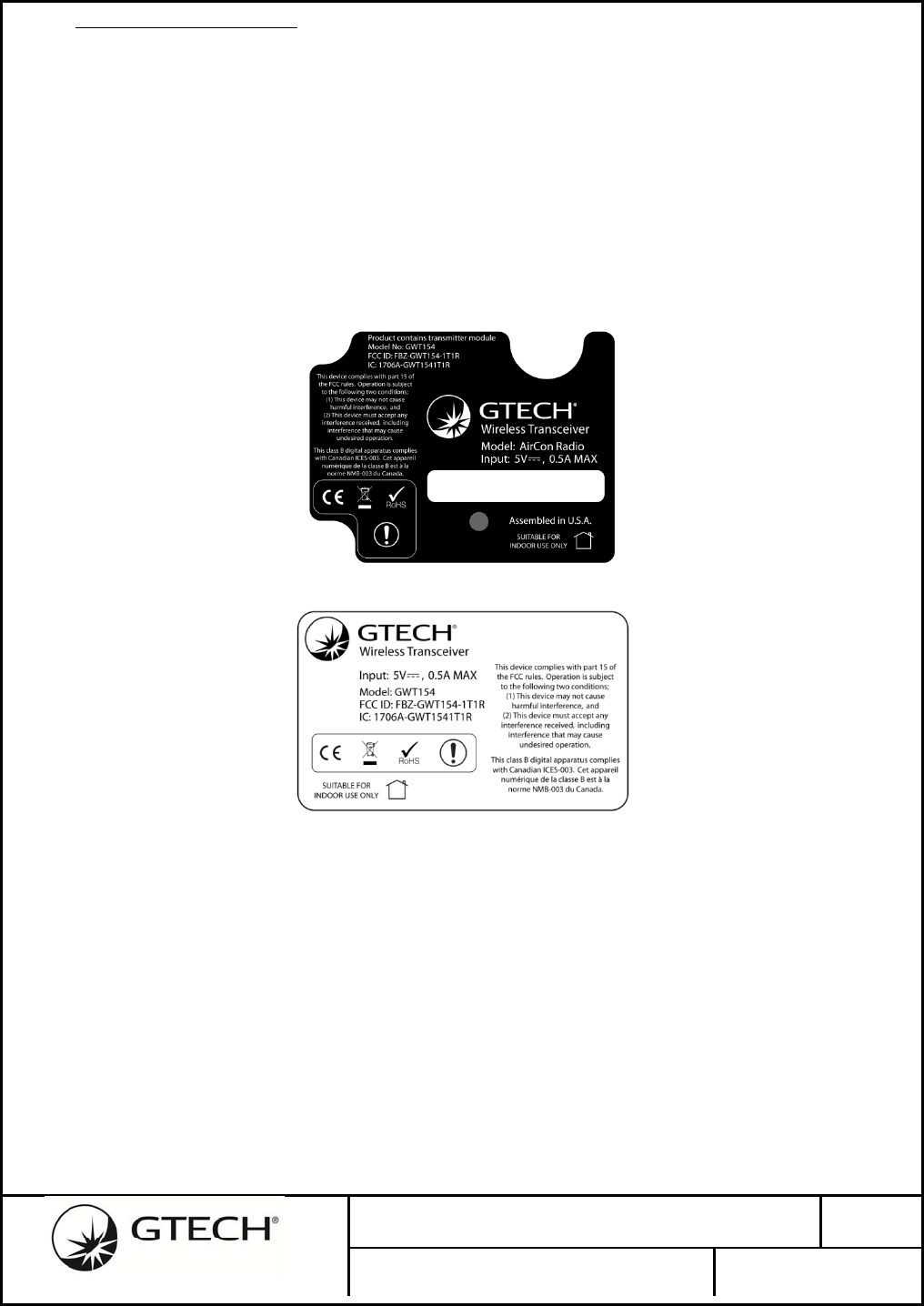
No. 96-1886-01E Rev.
1.1
GTECH Aircon Radio (Model GWT154)
PAGE 71 OF 72
10.4 EndProductLabelling
The GWT154 Radio Module is labeled with its own FCC ID and IC Certification Number. If the FCC
ID and IC Certification Number are not visible when the module is installed inside another device,
then the outside of the device into which the module is installed must also display a label referring to
the enclosed module. In that case, the final end product must be labeled in a visible area with the
following:
“Contains Transmitter Module FCC ID: FBZ-GWT154-1T1R”
“Contains Transmitter Module IC: 1706A-GWT1541T1R”
or
“Contains FCC ID: FBZ-GWT154-1T1R”
“Contains IC: 1706A-GWT1541T1R”
Figure 21 – Example of an End Product Label
Figure 22 – Example of a Model GWT154 Radio Module Label
The OEM of the GWT154 Radio Module must only use the approved antenna(s) listed above, which
have been certified with this module.
The OEM integrator has to be aware not to provide information to the end user regarding how to install
or remove this RF module or change RF related parameters in the user manual of the end product.
The user manual for the end product must include the following information in a prominent
location:
To comply with FCC and Industry Canada RF radiation exposure limits for
general population, the antenna(s) used for this transmitter must be installed
such that a minimum separation distance of 20cm is maintained between the
radiator (antenna) and all persons at all times and must not be co-located or
operating in conjunction with any other antenna or Revision History

No. 96-1886-01E Rev.
1.1
GTECH Aircon Radio (Model GWT154)
PAGE 72 OF 72
11.0 CONTACTING GTECH CORPORATION
Headquarters GTECH Center
10 Memorial Boulevard
Providence RI, 02903
USA
401-392-1000
Website http://www.gtech.com
Technical Support Ted Carr Sr. Product Compliance Specialist, 401-392-7721
Online Customer Service http://www.gtech.com/about_gtech/customer_net.asp
Sales Contact Dennis Hultzman, Director of Purchasing, 401-392-7383