GTO Access Systems MM136KP MIGHTY MULE RETAIL KEYPAD User Manual MM136
GTO Access Systems, LLC MIGHTY MULE RETAIL KEYPAD MM136
Users Manual
Crystal clear two-way communication up to 500 feet wireless.
Wireless Gate Entry Intercom
Thank you for purchasing the Mighty Mule Wireless Gate Entry Intercom.
Please read the directions carefully and completely before installing.
Instructions for Wireless and Wired Installations
Nortek Security & Control • Telephone (800) 543-4283 • Fax (850) 575-8912 • website www.mightymule.com
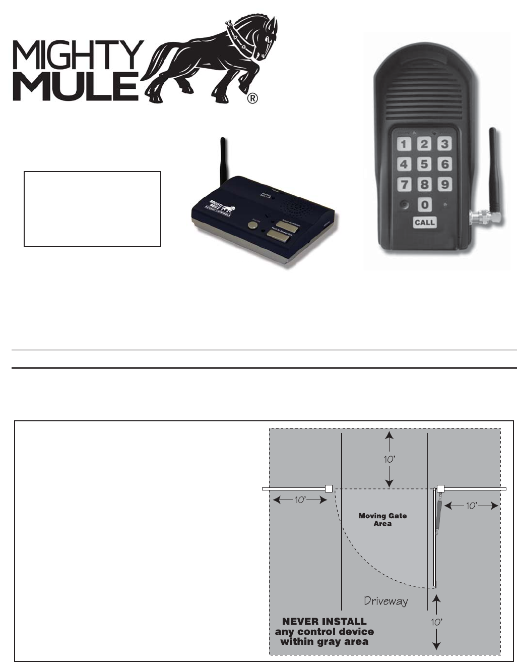
SAFETY NOTE: Never install the keypad
portion of this unit where a person can
reach through the gate to activate it, or
where a person can touch the gate while
activating the keypad. The recommended
minimum distance between the gate and
keypad is 10 ft.
©2017 Nortek Security & Controlrev - 1106-17
IMPORTANT: Allow the
intercom base unit’s battery
to charge for 12 hours before
time. See page 6 for details.
Keypad Unit
Base Unit
Base Unit

1
The INTERCOM has two separate units. The KEYPAD (outside unit) should be mounted outside the gate allowing the
driver of the vehicle approaching the property to press the CALL button from their vehicle. The BASE (inside unit), with
it’s rechargeable battery, can be plugged into any 110 Volt AC outlet for use while charging. It can also be disconnected
from the charger allowing it to go any where within range for convenience. Up to three additional BASES can be added
for convenience in different locations throughout the house.
When someone without an access code approaches the gate, they can press the CALL button on the keypad which will
ring the BASE unit inside the house. To answer the CALL, the person inside presses and holds the ANSWER button to
talk to the person at the gate, releasing the ANSWER button to listen. To allow the person calling to open the gate, the
GRANT PERMISSION button must be pressed. Then the person at the gate can press any number key on the KEYPAD
to open the gate. The “END CALL” button terminates the calls and the “ON/OFF” switch can be used to conserve power
when using unit on battery.
Up to 25 different personal entry codes may be programmed into the KEYPAD, allowing you to give different temporary
and permanent entry codes to different users. For example, you can give a delivery person their own temporary entry
code, which you can easily change after he has made the delivery. This will prevent him from being able to regain access,
while still allowing those to whom you gave permanent entry codes full access.
After entering a valid code, pressing any key on the KEYPAD while the gate is opening will stop the gate; pressing any
key while the gate is stopped will cause the gate to reverse direction. The KEYPAD will not affect the auto-close setting
of your gate opener system.
The KEYPAD number pad will light up and the unit will beep at the press of any key. The KEYPAD memory will rec-
string. This will discourage an unauthorized person from trying to use random numbers to access your property.
Your entry codes will remain stored in memory even when the batteries go dead. The KEYPAD will remember your entry
codes as long as you don’t press the RESET button.
Features of the Intercom/Keypad
IMPORTANT:
directly to the gate opener using 16 gauge (AWG) stranded, direct burial, low voltage wire (part no. RB509 not included).
See page 8 for details.
2
Wired Installation of the Keypad
NOTE: If you also plan to power the keypad with the gate opener’s battery and hard wire the com-
munication between the keypad and the gate opener, run two pairs of wires as described below. One
pair to hard-wire the keypad to the gate opener’s control board and the other pair to connect the
keypad to the gate opener’s battery.
Step 1: Turn the gate opener’s power switch OFF. Use 16 gauge (AWG) stranded, direct burial, low
voltage wire (part no. RB509) to connect the keypad to the opener control board. Run wire through
PVC pipe from the ground to keypad and from the ground to the opener control board to protect the
wire from lawn mowers or grazing animals.
Determine how the wire will enter the keypad (i.e. from the back through a hole drilled in the mount-
ing post or running the wire on the surface of the post). Remove the small rectangular knock-out on
the back of the keypad cover and pull the wire into the cover. Then mount the cover to the post using
the screws provided.
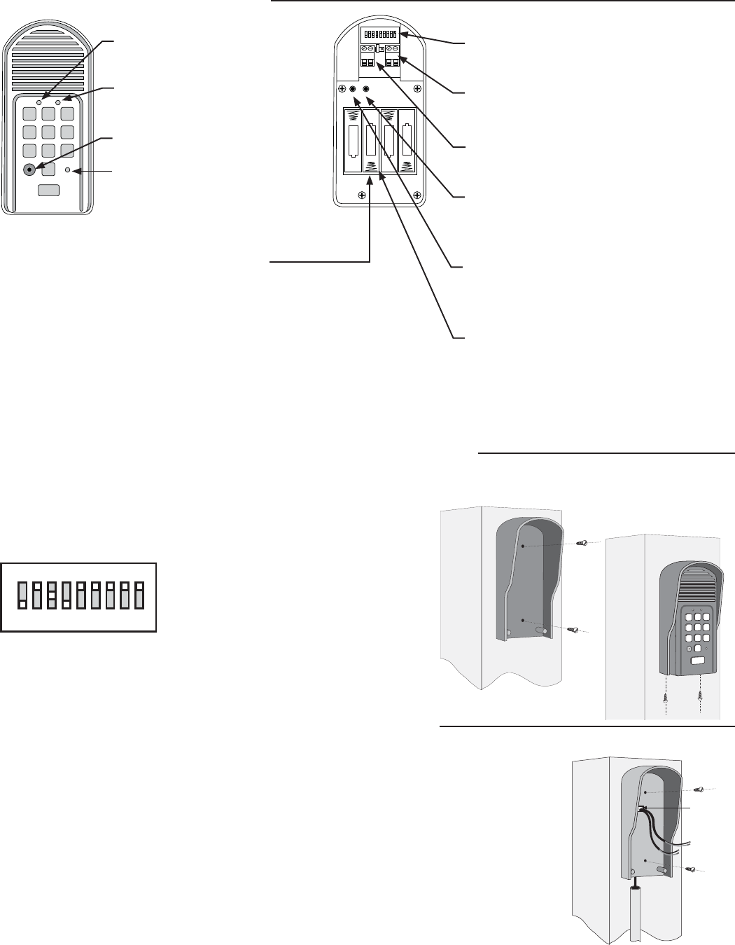
Keypad Description
Installing Batteries
keypad. If an external DC power supply such as the gate opener’s pow-
er source is used, the AA batteries will act as a back up. Low voltage
wire from the gate opener battery must be connected to the POWER IN
terminals on the keypad control board.
Step 1: Remove the two screws from the bottom of the keypad and
separate the keypad from its housing.
Step 2: Install four (4) AA batteries (not included).
1 2
ABC 3
DEF
4
GHI 5
JKL 6
MNO
7
PRS 8
TUV 9
WXY
0
CALL
STATUS
PROGRAM
CALLING GRANTED
STATUS Light:
This led will blink once when any
key is pressed and provides visual
feedback during access code
programming.
GRANTED Light:
LED turns GREEN when access
permission is granted.
Keypad - Front
Battery Holder:
Use 4 AA batteries if hard-wired power supply
is not used. If external power source is used the
4 AA batteries will provide a back-up power
source.
2%,!9
/54054
!#$#
0/7%2).
o
*%4&5
oo
o
o
3&4&5
+6.1&3
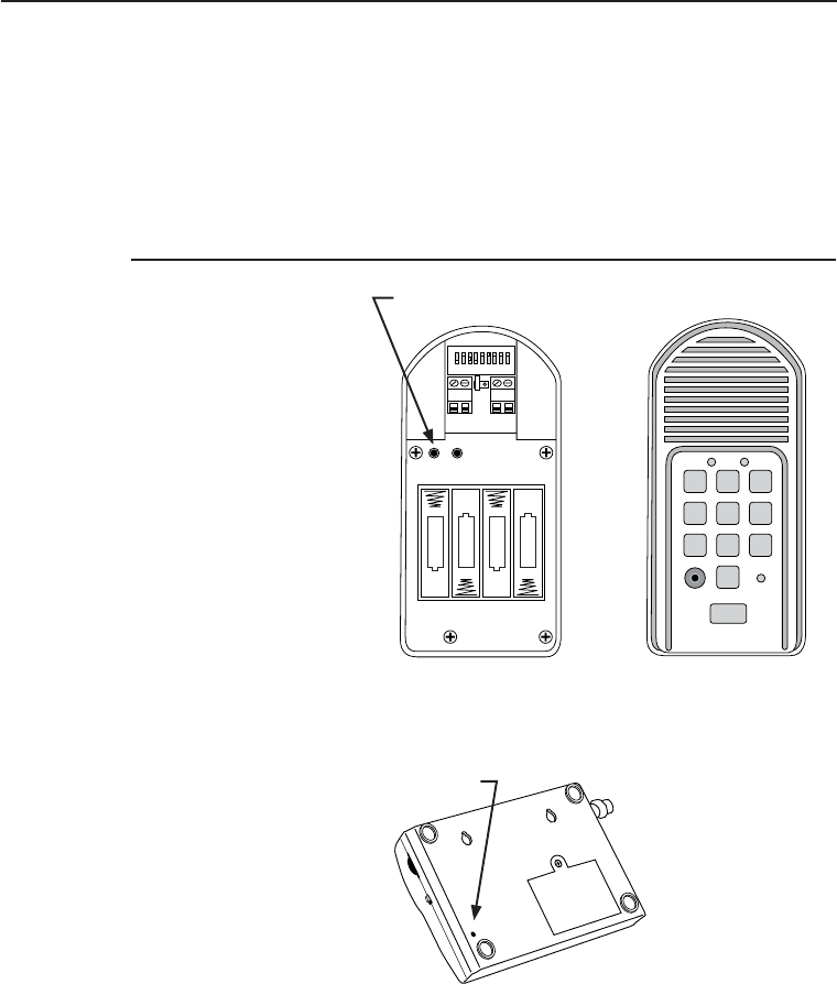
ID SET button:
This button is used only when there is another
pair of Mighty Mule wireless intercom units
nearby causing interference.
DIP Switches:
Match these switches to your remote
transmitter to program the keypad.
Relay output:
Used to connect the keypad to gate opener in
hard-wired applications.
Power Input:
Used to connect keypad to gate opener for
continuous power supply.
Keypad - Inside
Knock-out
Wireless Installation of the Keypad
NOTE: For wireless applications, the keypad must be in the line of sight of the gate opener receiver and the distance from the keypad
to the opener’s receiver should not exceed 50 ft. Always test the keypad range before permanently mounting it. A metal housing or
metal object could cause interference.
Step 1: Mount the keypad cover using the screws provided. Set the keypad
DIP switches to match your entry transmitter’s DIP switch settings.
NOTE: If you have not changed your opener’s
transmitter code from the factory setting, see
the “Setting Your Personal Transmitter Code”
section in the gate openers manual then set the
keypad DIP switches to match the new trans-
mitter DIP switch setting.
Step 2: Slide the keypad into the cover and secure with the small screws
provided.
12
ABC 3
DEF
4
GHI 5
JKL 6
MNO
7
PRS 8
TUV 9
WXY
0
CALL
STATUS
PROGRAM
CALLING GRANTED
123456789
+
0
–
PROGRAM button:
Used to program access codes.
CALLING Light:
LED is RED when calling and turns
GREEN when call is answered.
RESET button:
Pressing this button for 2 seconds will
reprogram the keypad to factory settings. All
codes are deleted. Default master code is 1234.
3
ON
ALARM ACCESSORY RCVR
SEQ1
SEQ2
LEARN
BLU
ORG
WHT
GRN
R B G
Connect #1 wire from the
RELAY OUTPUT terminals
on the keypad to WHT
terminal on the gate opener
control board.
Connect #2 wire
from the RELAY OUTPUT
terminals on the keypad to the
GRN terminal on the gate
opener control board.
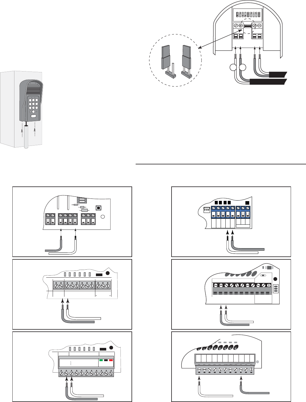
PRO-1000/2000, PRO-SL1000/SL2000 and Old Mighty Mule
Control Boards
#1
#2
RELAY
OUTPUT
AC/DC
POWER IN
123456789
+
0
–
Jumper ON
Jumper OFF
Hard-wire from Gate Opener
Power Supply from
Opener Battery
#1#2
Step 2: For hard-wired communication between the keypad and gate opener, using 16 gauge
(AWG) stranded, direct burial, low voltage wire (part no. RB509) strip the wires back 3/16”
and attach the wires to the terminal block marked RELAY OUTPUT on the keypad control
board as shown to the right. Connect the other end to the opener’s control board as shown in
Control Board Connections section below.
To wire the power supply to the keypad, attach the wires to the AC/
DC POWER IN terminal on the keypad control board as shown
to the right. Connect the other end to the opener’s battery - one
end to the POSITIVE (RED) pole and the other to the NEGA-
TIVE (BLACK) pole.
NOTE: For a hard-wired application
the jumper between the two terminals
on the keypad control board must be
connected (ON) as shown. This will
disable the 318 MHz RF transmitter.
Step 3: Slide the keypad into the cover and secure with the small screws provided.
Step 4: Turn the power to the opener OFF. Remove the opener control board cover and feed enough of the
low voltage wire from the keypad through a strain relief to reach the gate opener control board terminals.
Step 5: Attach the wires from the keypad to the opener control board terminal blocks as shown below.
Step 6: Replace the control board cover and turn the power switch ON. Test the keypad by entering 1 2 3 4.
Step 7: Program your ‘Personal Master Code’ and any additional entry codes (for a total of 25 entry codes).
See Programming the Keypad section.
Control Board Connections
12
ABC 3
DEF
4
GHI 5
JKL 6
MNO
7
PRS 8
TUV 9
WXY
0
CALL
STATUS
PROGRAM
CALLING GRANTED
NOTE: If your control board doesn’t look like any of these diagrams, please call Technical Service at 1-800-543-1236 or 850-
575-4144 for additional support.
GRN BLK RED
RECEIVER
COM COM
C
L
OS
E
CYCLE
CLOSE
SAFETY
EXIT
OPEN
SHADOW
LOOP
CLOSE
EDGE
OPEN
EDGE
J
1
1
J11 J8 J12
GTO/PRO DC Powered PRO-SW3000
and PRO-SW4000 Control Boards
Connect #1 wire from the
RELAY OUTPUT terminals on
the keypad to CYCLE terminal on
the gate opener control board.
Connect #2 wire from
the RELAY OUTPUT
terminals on the keypad
to the COM terminal on
the gate opener control
board. #1
#2
RECR
GRN
BLK
RED
EXIT
SAFETY
EDGE
CYCLE
COMMON
LINK
Mighty Mule 350 Control Board
Connect #1 wire from the
RELAY OUTPUT terminals
on the keypad to CYCLE
terminal on the gate opener
control board.
Connect #2 wire from the RELAY
OUTPUT terminals on the keypad
to the COMMMON terminal on
the gate opener control board.
#1
#2
RECEIVER
COM COM
CYCLE
CLOSE
SAFETY
EXIT/
OPEN
SHADOW
LOOP
CLOSE
EDGE
OPEN
EDGE
BLKGRN RED
Mighty Mule 500 & 502
Control Boards
Connect the #1 wire from
RELAY OUTPUT terminals on the
keypad to the CYCLE terminal on
the opener control board.
Connect the #2 wire from
the RELAY OUTPUT
terminals on the keypad to
one of the COMMON
terminals on the opener
control board. #1
#2
RECEIVER
ALM
GTO RCVR.
COM
GRN
BLK
RED
CYCLE
SAFETY
EXIT
SHADOW
OPEN
EDGE
COM
CONTROL INPUTS
CLOSE
EDGE
Connect #1 wire from
the RELAY OUTPUT terminals
on the keypad to CYCLE terminal
on the gate opener control board.
Connect #2 wire from the
RELAY OUTPUT terminals
on the keypad to the COM
terminal on the gate opener
control board. #1
#2
GEN-3 (Blue) Control Boards
COM
COM
COM
GTO Inc.
SX4000 L
CYCLE
SAFETY
OPEN EDGE
RUN 2
OPEN
CLOSE
STOP
COM
COM
COM
SHADOW
LOOP
Connect #1 wire from the
RELAY OUTPUT
terminals on the keypad to
CYCLE terminal on the
gate opener control board.
Connect #2 wire from the
RELAY OUTPUT terminals
on the keypad to the COM
terminal on the gate opener
control board.
#1
#2
GTO/PRO GP-SL100 and GP-SW100
Control Boards
4
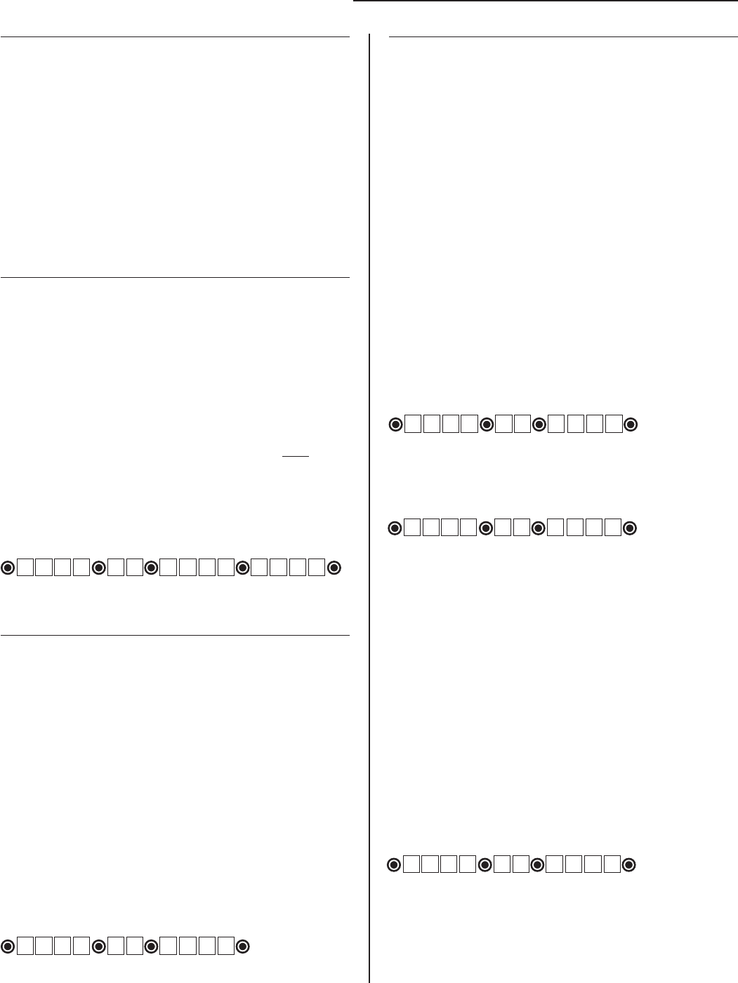
Programming Interface:
• All codes are four (4) digits in length.
• Entry code is a four (4) digit code needed to activate the gate.
• Master Code is needed to add, remove or reset entry codes.
• Master Code also functions as the entry code under normal
operation.
• Factory default Master Code is 1234.
• STATUS light should blink and beeper should beep (once)
whenever any button is pressed.
• If more than 10 seconds elapsed between key presses the unit
returns to normal (idle) operating mode.
• Keypad can only enter program mode from sleep mode
(keypad is turned OFF).
• Keypad will beep three times before going into sleep mode.
Program New Master Code:
• Press and release PROGRAM button.
• Enter the old Master Code then press and release PROGRAM
button.
• Enter 0, 6 then press and release PROGRAM button
• Enter the new Master Code then press and release PROGRAM
button.
• Enter the new Master Code then press and release PROGRAM
accepted.
NOTE: If the Master Code is not a matched pair or error occurs,
(i.e. if the entry code is NOT a 4-digit code) the STATUS light
returning to normal operation with old Master Code.
1 2 3 4 to 3 1 2 1
1 2 3 4 0 6 3 1 2 1 3 1 2 1
The round black dot is the ‘PROGRAM’ button.
Program (Add) New Entry Code:
• Press and release PROGRAM button.
• Enter the Master Code then press and release PROGRAM
button.
• Enter 0, 2 then press and release PROGRAM button.
NOTE: If memory is full (all 25 locations are already
programmed) the STATUS light
beeper will sound for 2 seconds before returning to normal
operation without saving.
• Enter the new Entry Code then press and release PROGRAM
button.
accepted.
NOTE: If the code is NOT 4-digits in length or an error
condition has occurred. The STATUS light
and the beeper will sound for 2 seconds before returning to
normal operation without saving.
code. (1234 is the Master Code)
The round black dot is the ‘PROGRAM’ button.
Program (Add) New Temporary Entry Code:
• Press and release PROGRAM button.
• Enter the Master Code then press and release PROGRAM
button.
• Enter 8, and any number between 1 thru 7 then press and
release the PROGRAM button. The number 1 thru 7 indicates
the number of days after which the code will be automatically
removed from memory
NOTE: If memory is full (all 25 locations are already
programmed) or an invalid entry is detected, then an error
condition has occurred. The STATUS light
and the beeper will sound for 2 seconds before returning to
normal operation without saving.
• Enter the new Entry Code then press and release PROGRAM
button.
accepted.
NOTE: If the code is NOT 4-digits in length or an error
condition has occurred, the STATUS light
and the beeper will sound for 2 seconds before returning to
normal operation without saving.
code that will remain valid for 2-days only. (1234 is the
Master Code)
The round black dot is the ‘PROGRAM’ button.
code that will remain valid for 7-days only. (1234 is the
Master Code)
The round black dot is the ‘PROGRAM’ button.
Programming the Keypad
Delete An Entry Code:
• Press and release PROGRAM button.
• Enter the Master Code then press and release PROGRAM
button.
• Enter 0, 3 then press and release PROGRAM button.
• Enter the Entry Code to be deleted then press and release
PROGRAM button.
deleted.
NOTE: If no matching code is found or the code is NOT 4-digit
in length, then an error condition has occurred. The STATUS
light
before returning to normal operation without saving.
memory. (1234 is the Master Code)
The round black dot is the ‘PROGRAM’ button.
1 2 3 4 0 2 3 4 5 6
1 2 3 4 8 2 3 4 5 6
1 2 3 4 0 3 3 4 5 6
1 2 3 4 8 7 3 4 5 6
5
Intercom Description
Normal Keypad operation:
• If the user enters a 4-digit code that is matched to one of the
25 stored codes, the STATUS light should blink twice and the
entered.
• No more than 20 key presses are allowed to obtain the 4-digit
entry code.
Example:
1234 is one of the codes stored in one of the memory location.
The user can enter ‘x1234’ or ‘xxxxxxxxxxxxxxxx1234’ and
the gate should be activated (x is any key). If more than 20 key
presses is entered without matching one of the codes, then the
accepted for the next 40 seconds. The user must not enter any
code for at least 40 seconds before the unit returns to normal
operation. Otherwise it remains in this ‘lock-down’ mode. Once
the user enters a matched code, any subsequent key press
within the next 40 seconds will re-activate the keypad.
Delete ALL Entry Codes:
• Press and release PROGRAM button.
• Enter the Master Code then press and release PROGRAM
button.
• Enter 0, 7 then press and release PROGRAM button.
deleted.
memory. (1234 is the Master Code)
The round black dot is the ‘PROGRAM’ button.
1 2 3 4 0 7
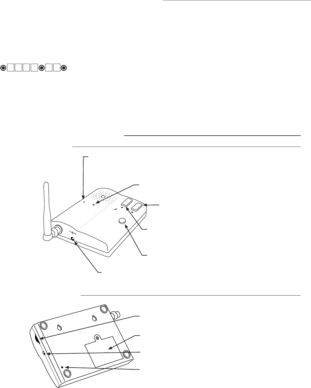
GRANT ACCESS Button:
The GRANT PERMISSION button must be pressed then
the person at the keypad can press any key to open the gate.
Intercom - Face
PUSH TO ANSWER/TALK Button:
Used to answer CALL from keypad.
HOLD to talk - RELEASE to listen.
POWER
Keypad
Batt Low
Grant Permission
Push To Answer/Talk
End Call
DV 9V
POWER Light:
LED is GREEN when charging on AC power source and RED during battery
power mode. Blinking RED indicates low battery on Base unit.
KEYPAD BATTERY INDICATOR Light:
LED turns ON when keypad battery is low.
9 Vdc Transformer Plug:
Transformer plugs here to charge the base unit battery.
ID SET
VOLUME
POWER
OFF ON
Intercom - Bottom
ON/OFF Switch:
Turn OFF to conserver power when battery operated.
VOLUME Control:
Controls volume level of speaker.
ID SET button:
This button is used only when there is another pair of
wireless intercom units nearby causing interference.
END CALL Button:
Allows user to terminate the call.
BATTERY ACCESS Cover:
Rechargable 3.6 Volt Ni-MH battery included.
6
Intercom Base Unit Installation
Find a convenient location near an approved outlet to
mount or place the intercom. Plug the transformer into
the AC outlet and connect it to the intercom’s power
jack marked DC 9V.
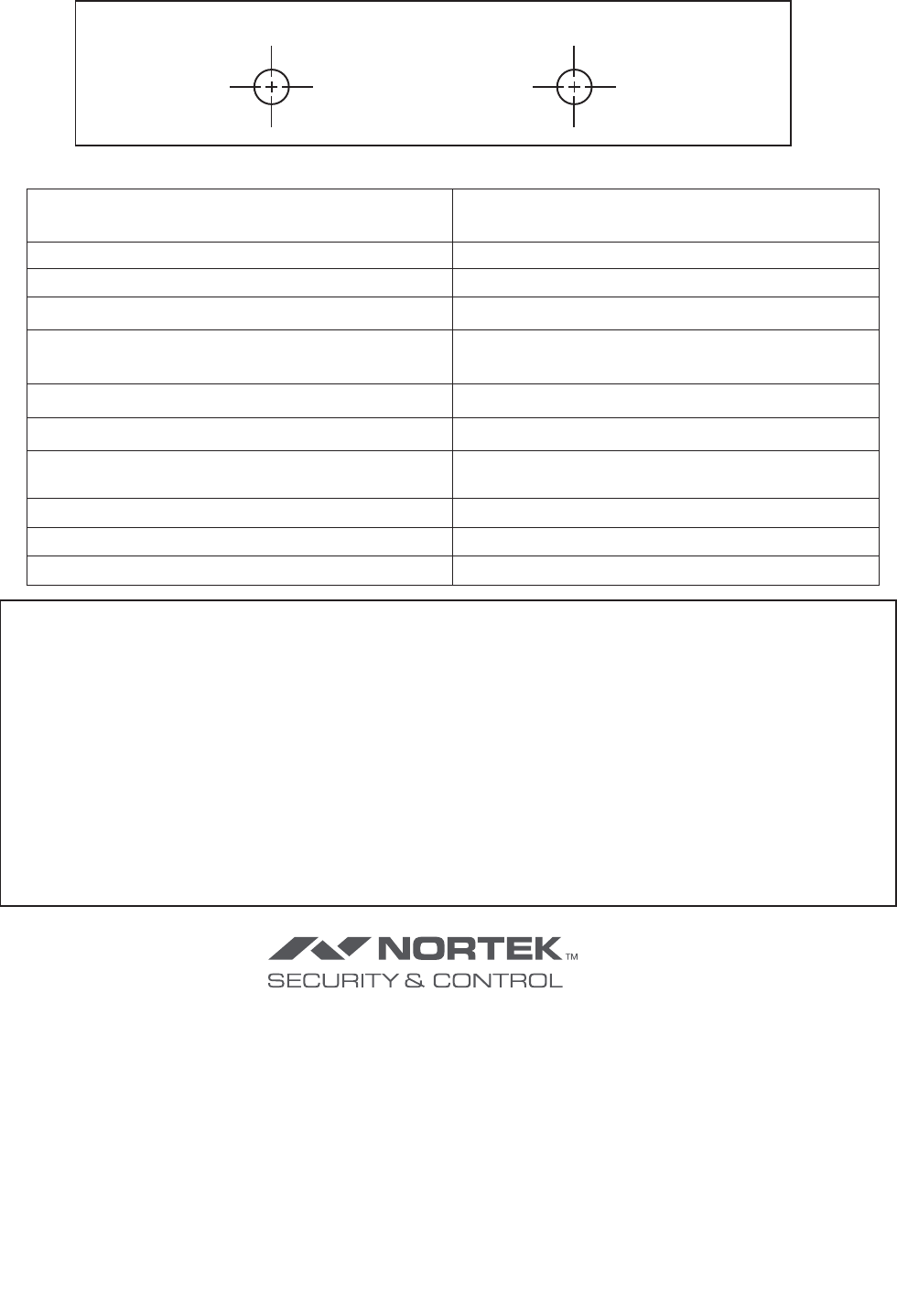
If you are mounting the intercom on the wall, use the
template on the last page of this manual to place screws.
The intercom can be disconnected from the transformer
and used as a battery powered unit. It can be moved to
any convenient location, i.e. bedroom, patio, or garden
area.
IMPORTANT: When the Intercom unit is ON it is in
the receive mode. When plugged into the transformer
it is constantly charging the battery. The battery will
last approximately four (4) hours when unplugged from
the transformer. You can turn the unit OFF to conserve
battery power but it will not receive a signal when OFF.
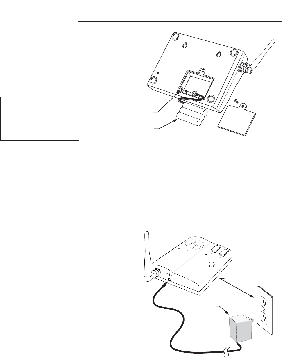
Remove the battery access cover using a small
phillips head screwdriver. Plug the rechargeable
Ni-MH battery into the receptacle inside the
battery compartment. See diagram to the right.
When this is done, replace the battery access
cover.
Connecting the Battery
Connecting the Transformer
ID SET
Battery Plug
Battery
POWER
Keypad
Batt Low
Grant Permission
Push To Answer/Talk
End Call
DV 9V
Transformer
Approved 110 Vac outlet
IMPORTANT: Once connected, allow the intercom
base unit’s battery to charge for 12 hours before us-
IMPORTANT: Allow the
intercom base unit’s battery
to charge for 12 hours before
time. See page 7 for details.
7
Adding Additional Base Units
Batteries must be installed and the units turned ON.
1. Press and release the “ID SET” button on the Keypad.
2. Press the number on the Keypad that corresponds to
the Intercom you are adding or changing. You will hear
the number of beeps corresponding to the number you
pressed.
For Example: If you are adding a third base unit to the
system PRESS #3. The keypad will beep THREE times.
3. Press the “ID SET” button on the base unit until it beeps
then release. You will hear beeps from the base unit and
beeps from the keypad, which means the ID Codes are
set.
with at least 10 feet between them to prevent interference.
2%,!9
/54054
!#$#
0/7%2).
o
*%4&5
oo
o
o
3&4&5
+6.1&3
ID SET button
ID SET
VOLUME
POWER
OFF ON
Keypad - Inside
Intercom - Bottom
1 2
ABC 3
DEF
4
GHI 5
JKL 6
MNO
7
PRS 8
TUV 9
WXY
0
CALL
STATUS
PROGRAM
CALLING GRANTED
Keypad - Front
ID SET button
Intercom ID Codes
The Base and Keypad that came in this kit are programmed at the factory to communicate with each
other, and do not need the ID Codes programmed. This Base is the MASTER or #1 unit.
If you have purchased additional Base units to
enhance your system, each additional unit’s ID
Code must be programmed into the Keypad so
they can communicate. Follow the steps below to
set the ID codes.
8
Test the System
IMPORTANT: The Base unit and the Keypad can not be within 30 feet of each other when operating. If units are
closer than 30 feet the signal will be inconsistent as well as emit speaker feed back. Also, multiple Base units must be
no closer than 10 feet from each other to prevent interference.
Have someone press the CALL button on the keypad at the gate. When the base unit inside the house rings, press
the ANSWER button and talk to the person at the gate to check the connection and range. Then press the GRANT
PERMISSION button and have the person at the gate press any key on the keypad to activate the gate.
Trouble Shooting
Make sure all connections are secure and correct.
Other electronic devices in the same area may interfere with the factory ID code. If the system does not communicate
at all, reset the intercom/keypad ID code as follows.
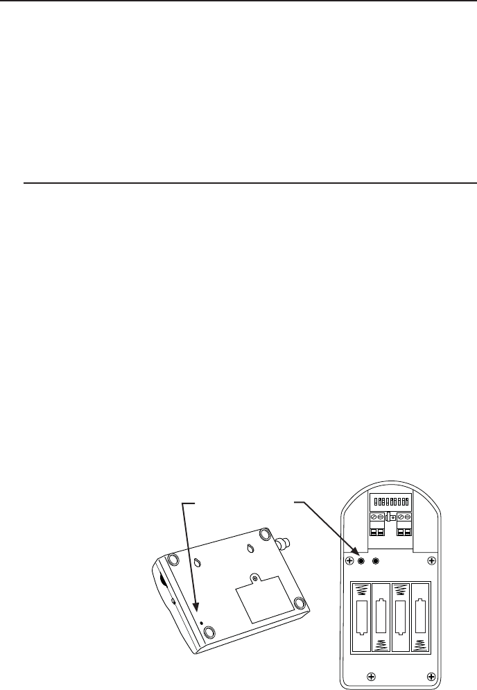
1. Open the keypad and locate the “ID SET” button above the batteries.
2. Locate the “ID SET” button on the bottom of the intercom base unit.
3. Make sure the “antenna-to-antenna” distance between the keypad and the base unit is at least 30 feet.
4. Reset the MASTER Intercom base unit’s ID Code.
IMPORTANT: Base units must be no closer than 10 feet from each other to prevent interference.
Batteries must be installed and the units turned ON.
A. Press the “ID SET” button on the Keypad until you
hear a beep, then release. This erases all stored ID
Codes.
B. Press the “ID SET” button on the MASTER Inter-
com for approximately 2 seconds then release. You
will hear ONE beep from the Intercom and TWO
from the Keypad, which means the ID Codes are
reset.
C. Test the system by pressing the CALL button on the
Keypad to see if the Intercom receives the signal.
NOTE: If the system is now working you will need to
reset any additional Intercom you have installed. See
“Adding Additional Intercoms”.
2%,!9
/54054
!#$#
0/7%2).
o
*%4&5
oo
o
o
3&4&5
+6.1&3
ID SET buttons
ID SET
VOLUME
POWER
OFF ON
Keypad - Inside
Intercom - Bottom
If all connections are correct and the ID SET change didn’t solve the communication problem, please call our
Technical Service Department at 1-800-543-1236 Monday - Friday 8:00 am to 7:00 p.m. (ET).
9
Limited One Year Warranty
Nortek Security & Control (NSC) gate opener accessories are warranted by the manufacturer against defects in workmanship for a period of one (1) year from the date of
purchase, provided recommended installation procedures have been followed.
In the case of product failure due to defective material or manufacturer workmanship within the one (1) year warranty period, the accessory will be repaired or replaced (at
the manufacturer’s option) at no charge to the customer, if returned freight prepaid to Nortek Security & Control. IMPORTANT: Call 850/575-4144 or fax 850/575-8950
for a Return Goods Authorization (RGA) number before returning goods to factory. Products received at the factory without an RGA will not be accepted. Replacement
or repaired parts are covered by this warranty for the remainder of the one (1) year warranty period. NSC will pay the shipping charges for return to the owner of items
repaired.
The manufacturer will not be responsible for any charges or damages incurred in the removal of the defective parts for repair, or for the re-installation of those parts after
repair. This warranty shall be considered void if damage to the product(s) was due to improper installation or use, connection to an improper power source, tampering, or
After the one (1) year warranty period, NSC or one of its authorized service centers will make any necessary repairs for a nominal fee. Call NSC at 850/575-4144 for more
-
Monday thru Friday 8:00 am to 7:00 p.m. (ET) at 1-800-543-1236.
Nortek Security & Control • Telephone (800) 543-4283 • Fax (850) 575-8912 • website www.mightymule.com
Hole Template for Mounting the Base Unit
The contents of all material available on this installation manual are copyrighted by Nortek Security & Control (“NSC”), unless otherwise indicated. All rights are reserved by NSC, and content
may not be reproduced, downloaded, disseminated, published, or transferred in any form or by any means, except with the prior, written permission of NSC. Any reprinting of NSC publica-
tions is by permission only. Copyright infringement is a violation of federal law.
GTO®, GTO/PRO®, Mighty Mule® are registered trademarks of Nortek Security & Control. GTO Access Systems™ is a trademark of Nortek Security & Control and are the exclusive prop-
erty of Nortek Security & Control (“NSC”). All rights are reserved by NSC, and these marks may not be used, in any for without the prior, written permission of NSC.
318MHz from keypad to gate opener
900MHz from keypad to base station
Memory - Keypad Stores up to 25 four digit entry codes
Power Consumption – Keypad 60 ma when relay is closed
Power Supply – Keypad 8-24v dc/ac or four AA batteries
Power Supply – Base Station 9 vdc 300ma transformer; 3.6V Ni-MH 800ma
rechargeable battery pack
Range from keypad to base station 500’ wireless
Range from keypad to gate opener 50’ wireless 100’ wired using 16 awg wire
Relay Output – Keypad Momentary, dry, normally open contact closes for 2
seconds upon activation
Relay Output Rating – Keypad 12 or 24vdc 100ma
Wiring – Base & Keypad Antennas RG6 or RG59 Coaxial Cable
Wiring – Keypad Power & Relay Output 16 awg stranded low voltage direct burial wire
USA & Canada (800) 421-1587 & (800) 392-0123
(760) 438-7000 - Toll Free FAX (800) 468-1340
www.nortekcontrol.com
Cet équipement doit être installé et utiliséavec une distance minimale de cm entre leradiateur
ISEDC RSS
warning
7KLVGHYLFHFRP SOLHVZLWK,6('&OLFHQFHH[HPSW566VWDQGDUGV2SHUDWLRQ LV
VXEMHFWWRWKHIROORZLQJWZRFRQGLWLRQVWKLVGHYLFHP D\QRW FDXVHLQWHUIHUHQFH
DQGWKLVGHYLFHPXVWDFFHSWDQ\LQWH UIHUHQFHLQFOXGLQJLQWHUIHUHQFHWKDWPD\
FDXVHXQGHVLUHGRSHUDWLRQRIWKHGHYLFH
Le présent appareil est conforme aux CNR d'ISEDC applicables aux appareils radio
exempts de licence.
L'exploitation est autorisée aux deux conditions suivantes:
(1) l'appareil ne doit pas produire de brouillage, et
(2) l'utilisateur de l'appareil doit accepter tout brouillage radioélectrique subi, même
si le brouillage est susceptible d'en compromettre le fonctionnement.
ISEDC Radiation Exposure Statement:
7KLVHTXLS PHQWFRP SOLHVZLWK,6('&5)UDGLDWLRQH[SRVXUHOLPLWVVHWIRUWKIRUDQ
XQFRQWUROOHGHQYLURQP HQW7KLVWUDQVPLWWHUPXVWQRWEHFRORFDWHGRU RSHUDWLQJLQ
FRQMXQFWLRQZLWKDQ\RWKHUDQWHQQDRUWUDQVPLWWHU
Rapport d'exposition de la radiation d' ISEDC :
&HWpTXLSHPHQWHVWFR QIRUPHDX[OLP LWHVGH[SRVLWLRQGDWLRQGHUDGLGHO,6('&UI
GpWHUPLQpHVSRXUXQHQYLURQQHP HQWQRQFRQW U{Op&HWpP HWWHXUQHGRLWSDVrWUH
&RSODFpRXIRQFWLRQQDQWGDQVODFRQMRQFWLRQDYHFDXFXQHDXWUHDQWHQQHRXpPHWWHXU
radiator& your body.
& votre corps.
AnyChangesor modificationsnotexpresslyapprovedbythepartyresponsibleforcompliance
couldvoidtheuser’sauthoritytooperatetheequipment.
Thisdevicecomplieswithpart15oftheFCCRules.Operationissubjecttothefollowingtwo
conditions:(1)Thisdevicemaynotcauseharmfulinterference,and(2)thisdevicemustaccept
any
interference
received,
including
interference
that
may
cause
undesired
operation.
Note:ThisequipmenthasbeentestedandfoundtocomplywiththelimitsforaClassBdigital
device,pursuanttopart15oftheFCCRules.Theselimitsaredesignedtoprovidereasonable
protectionagainstharmfulinterferenceinaresidentialinstallation.Thisequipmentgenerates
usesandcanradiateradiofrequencyenergyand,ifnotinstalledandusedinaccordancewiththe
instructions,maycauseharmfulinterferencetoradiocommunications.However,thereisno
guaranteethatinterferencewillnotoccurinaparticularinstallation.Ifthisequipmentdoes
causeharmfulinterferencetoradioortelevisionreception,whichcanbedeterminedbyturning
theequipmentoffandon,theuserisencouragedtotrytocorrecttheinterferencebyoneor
moreofthefollowingmeasures:
‐‐Reorientorrelocatethereceivingantenna.
‐‐Increasetheseparationbetweentheequipmentandreceiver.
‐‐Connecttheequipmentintoanoutletonacircuitdifferentfromthattowhichthereceiveris
connected.
‐‐Consultthedealeroranexperiencedradio/TVtechnicianforhelp.
20
FCC RF Radiation Exposure Statement
This equipment complies with FCC radiation exposure limits set forth for an uncontrolled
environment. End users must follow the specific operating instructions for satisfying RF
exposure compliance. This transmitter must not be co-located or operating in conjunction
with any other antenna or transmitter. This equipments
between the
20cm
should be installed and operated with
minimum distance radiator& your body.
between the
20cm
This equipments should be
installed and operated with minimum distance