GUARDIAN ACRX01-CC Garage Door Opener User Manual
GUARDIAN SHANGHAI CORP. Garage Door Opener Users Manual
GUARDIAN >
Users Manual

Owner’s Manual
●Please read and understand this manual and safety instructions carefully before installation.
●The Opener WILL NOT CLOSE until the Photo Eye Safety System is properly installed and aligned.
●REGULARLY CHECK and TEST the Opener according to the safety label to ENSURE SAFE OPERATION.
●Retain this manual for future reference.
GDO Manual Revised: 03-17 GDOMU10A-7
WARNING:
To reduce the risk of injury to persons - Use this operator only with Residential Sectional Garage doors.
Serial # __ __ __ __ __ __ __ Date Installed __ __ /__ __ /__ __ __ __
Located on the bar code label on top of your opener.
The illustrations used in this instruction manual may differ from the actual product you have purchased.
1
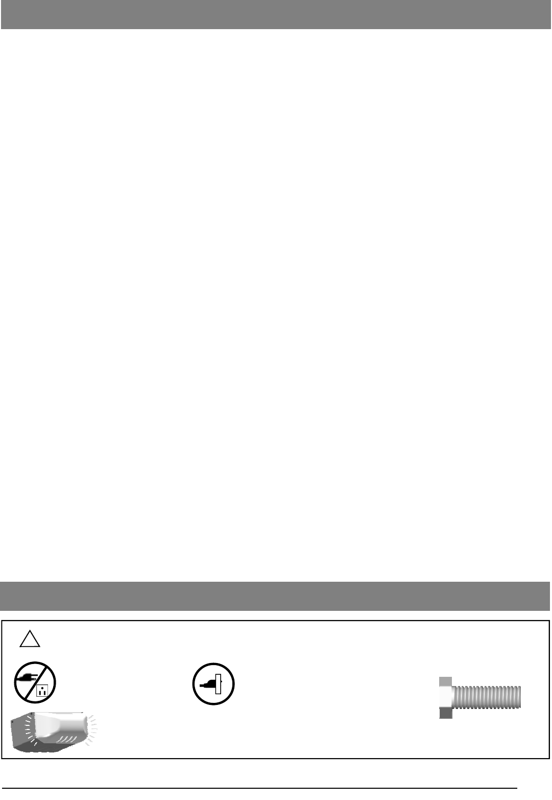
Courtesy light turns on/flashes with audible ‘click’.
(If light bulb is not installed, ‘click’ represents the light)
DO NOT connect power Please connect power
Symbols and Icons
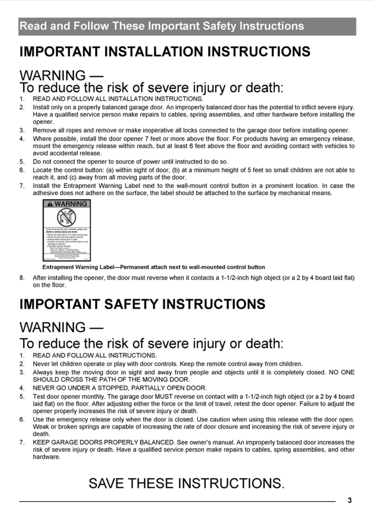
! WARNING
Installation hardware
Introduction
Symbols and Icons 1
Inventory 2
Read and Follow These Important Safety Instructions 3
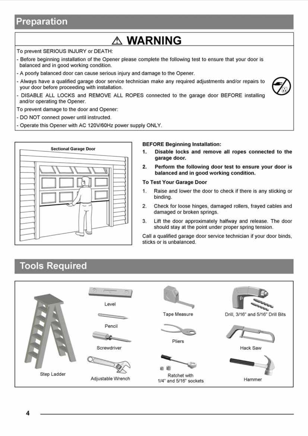
Preparation / Door Balance Test 4
Tools Required 4
Assembly
T-rail Assembly and Tensioning 5
Mounting Header Bracket 6
Installation
Attaching the Opener Assembly to Header Bracket 7
Mounting Door Bracket 7
Mounting Opener to Ceiling 8
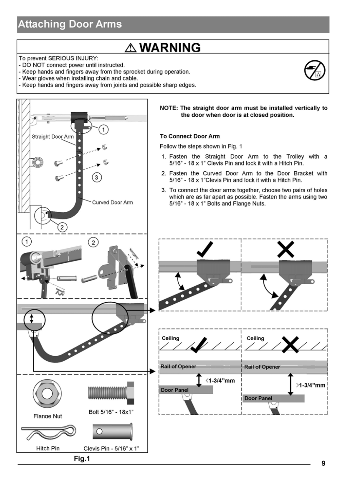
Attaching Door Arms 9
Installing Light and Emergency Release Handle 10
Wiring
Wiring Instructions 11
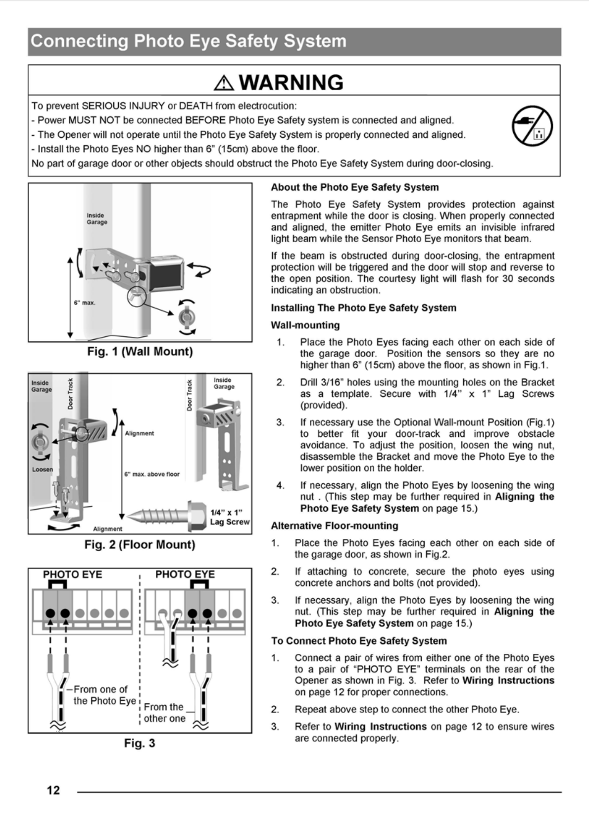
Connecting Photo Eye Safety System 12
Connecting Push Button 13
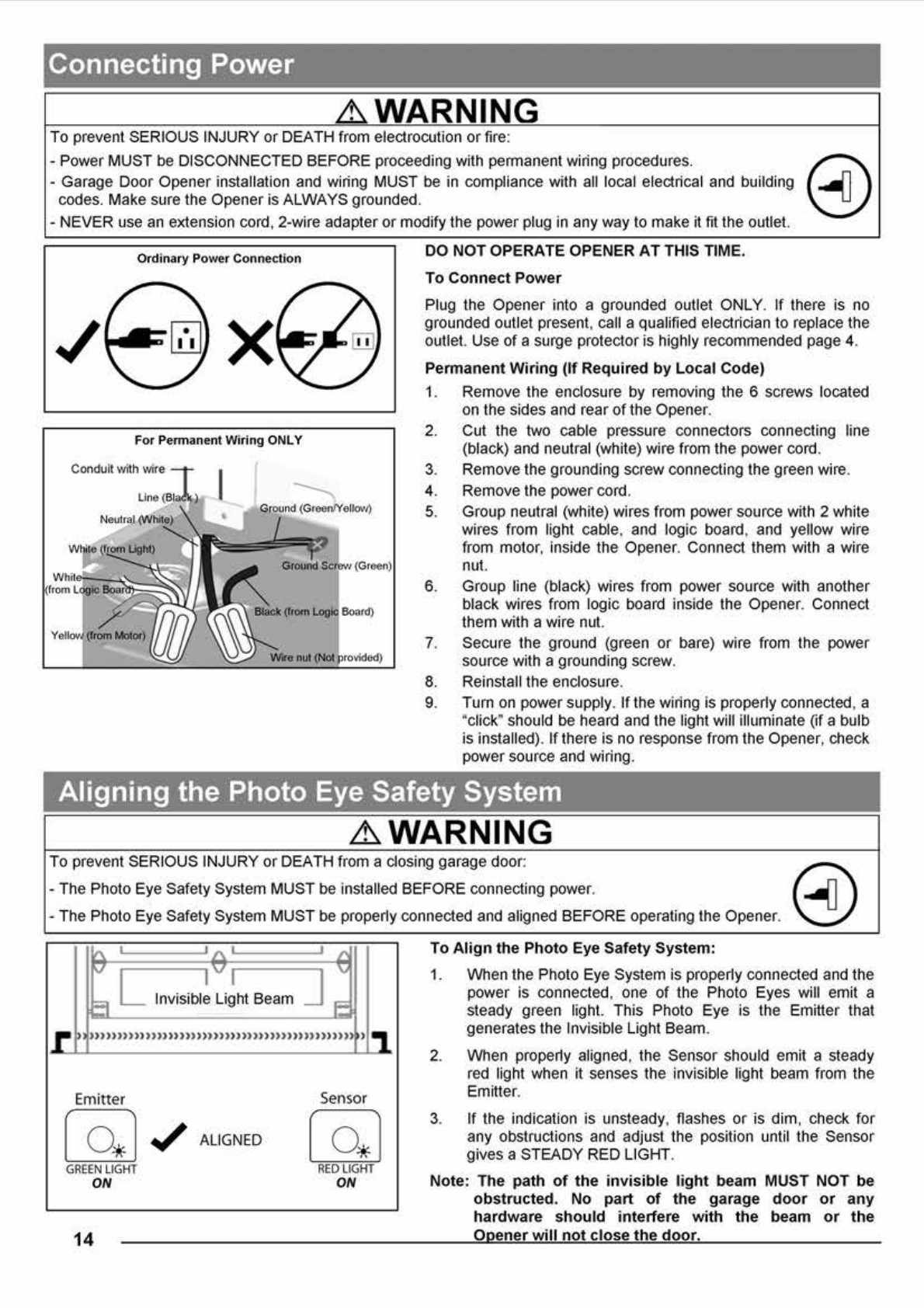
Connecting Power 14
Adjustment
Aligning the Photo Eye Safety System 14
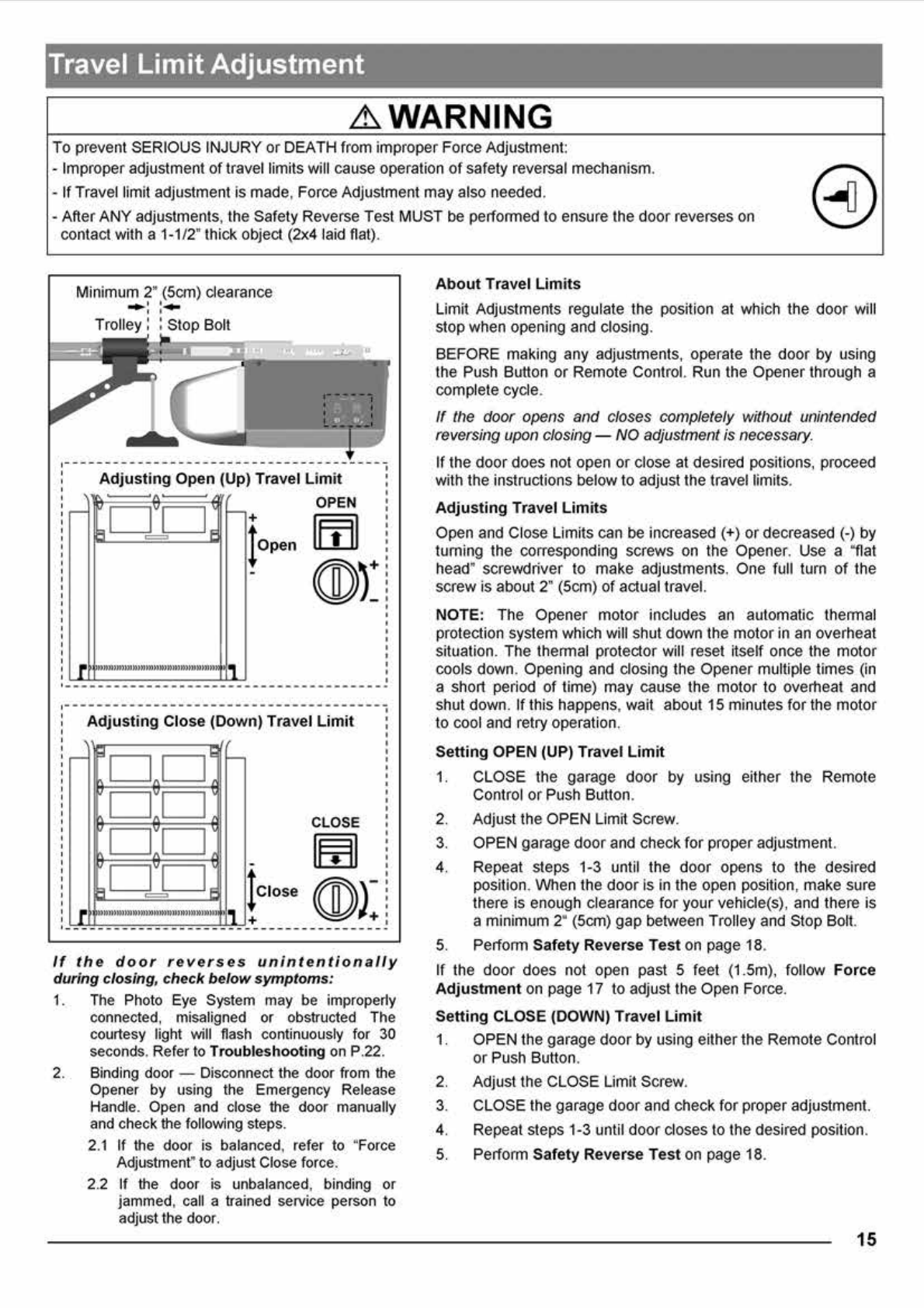
Travel Limit Adjustment 15
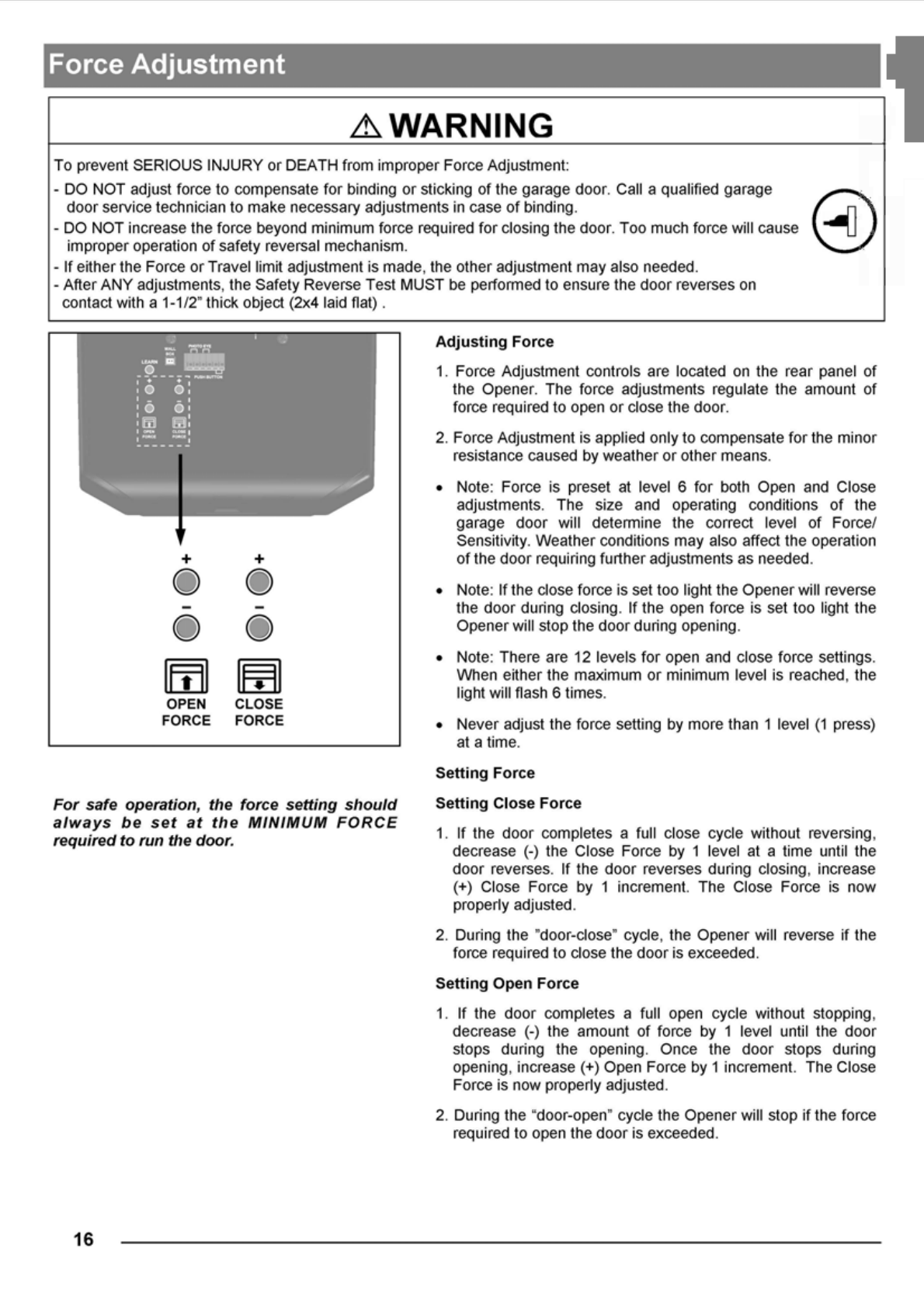
Force Adjustment 16
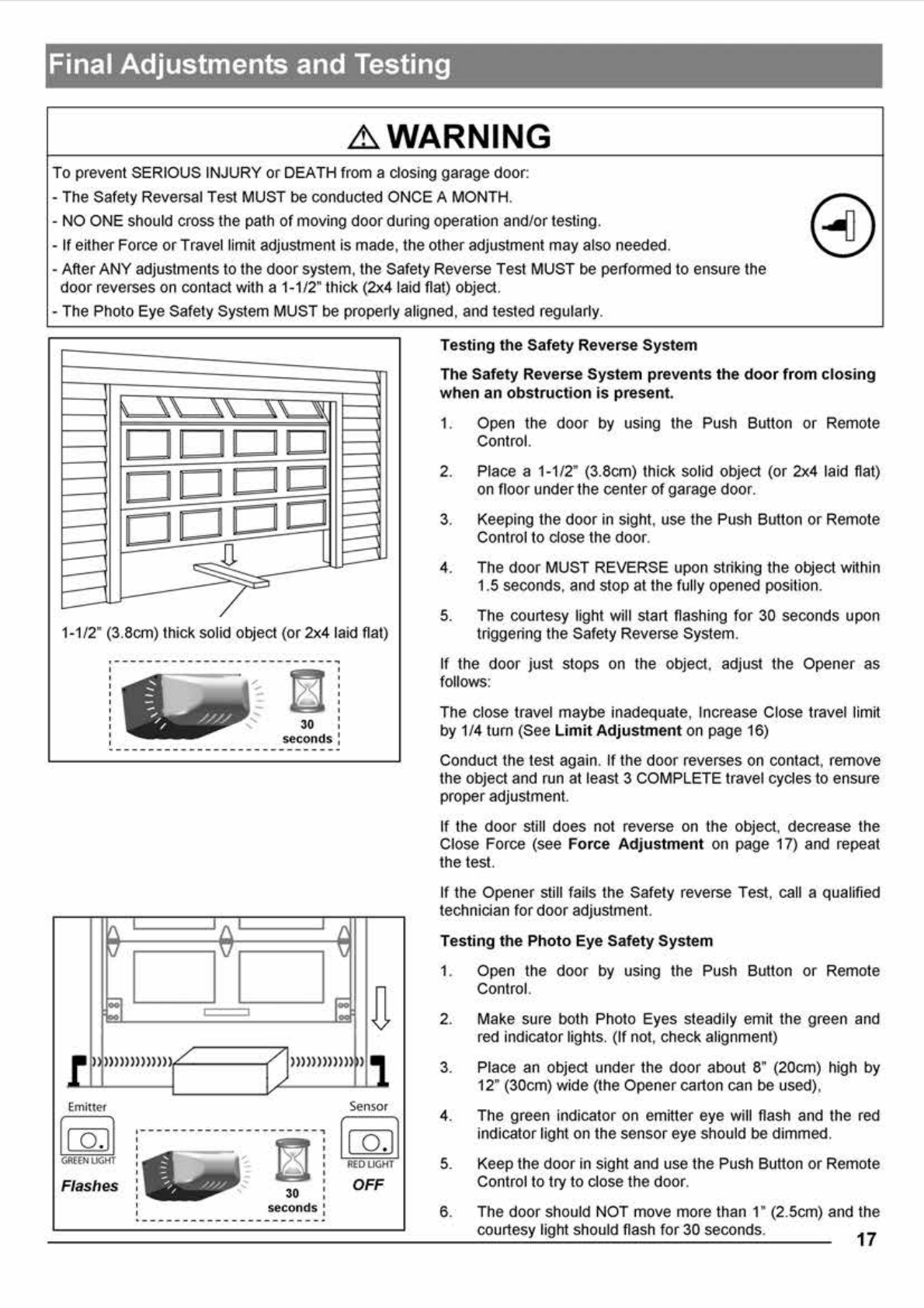
Final Adjustment and Testing 17
Operation
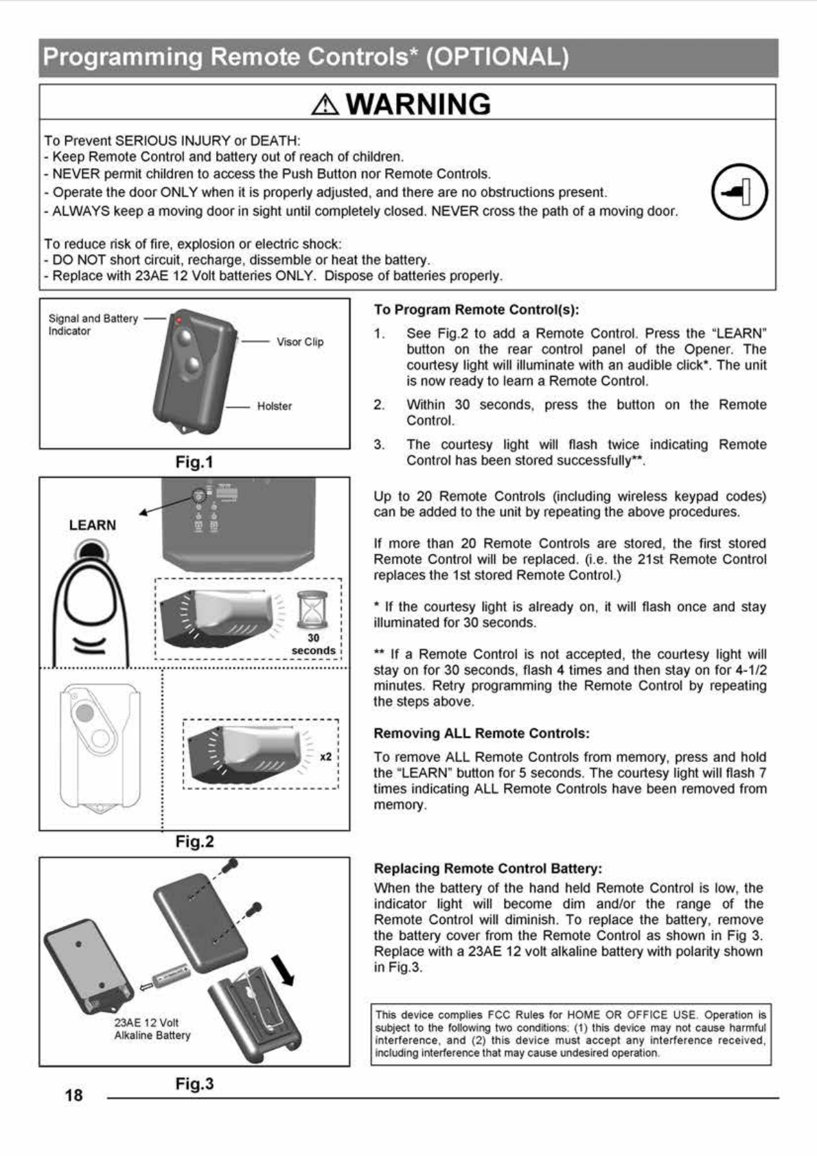
Programming Remote Controls* (OPTIONAL) 18
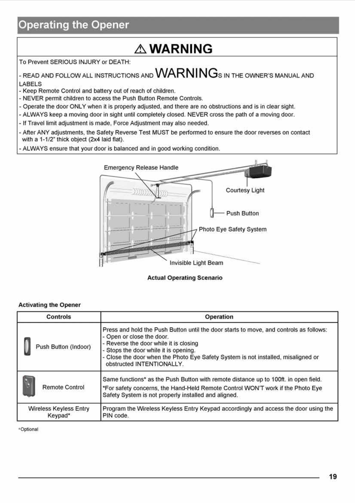
Operating the Opener 19-20
Maintenance 21
Troubleshooting 21
Repair Parts and Service
Installation and Accessory Parts 22
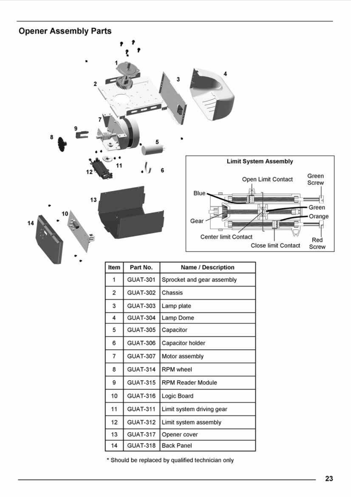
Opener Assembly parts 23
Warranty 24
Table of Contents
READ WARNINGS CAREFULLY to prevent SERIOUS INJURY or
DEATH caused by electrocution or mechanical hazard.
2
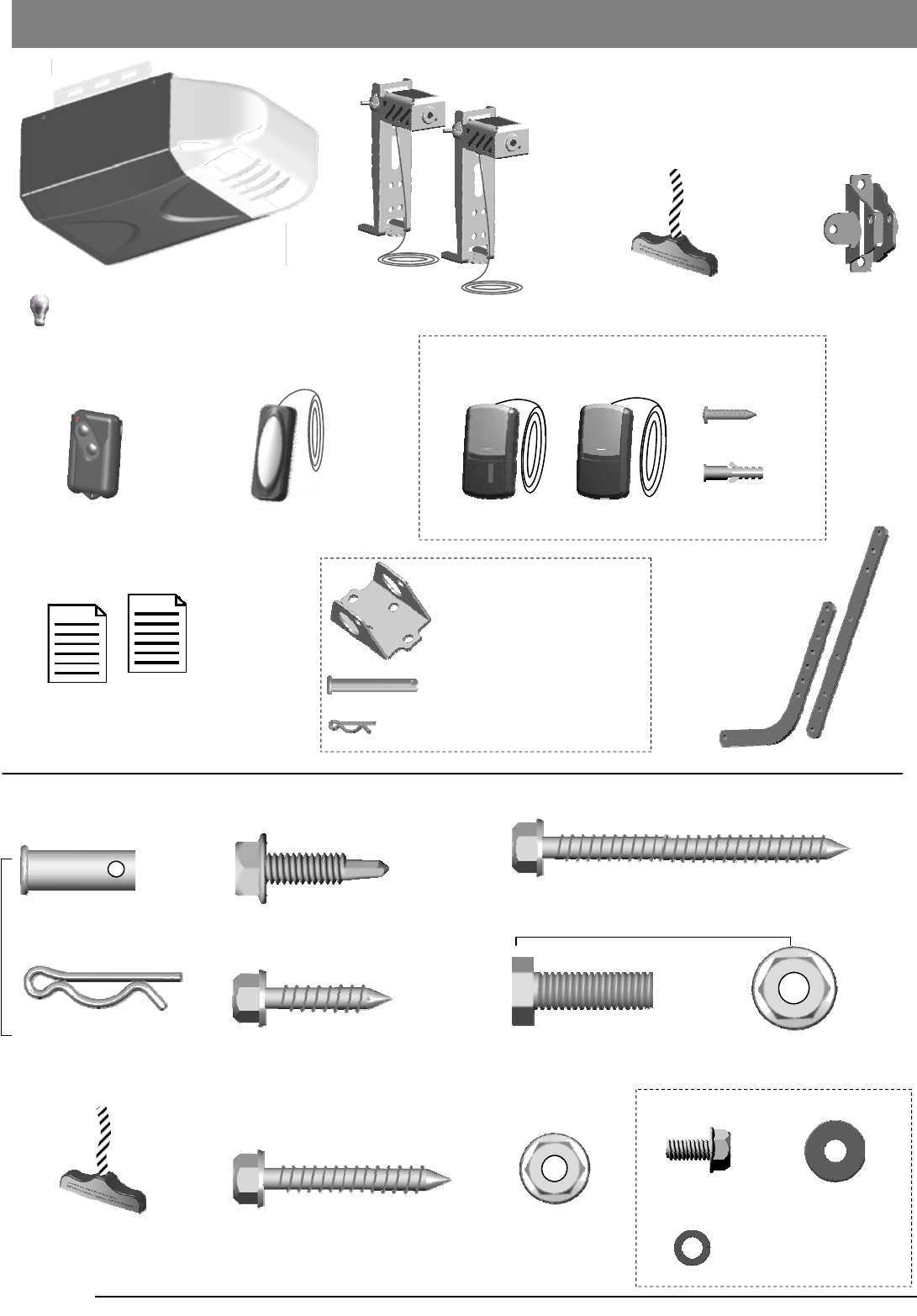
Emergency Release Handle
+ Rope
Literature + Safety Labels
Photo Eye Safety System Door Bracket
Door Arms
Inventory
Remote Control Push Button
Header Bracket
Clevis Pin Long x1
5/16’’ x 2-1/4’’
Hitch Pin — Locking Clevis Pins x1
x 2
Hitch Pin
— Locking Clevis Pins
x 2
Lag Screw 5/16” x 1-5/8”
— Door Bracket / Mounting Opener
Bolt 5/16” -18 x 1” 5/16” Flange Nut
x 6 x 6
x 4
x 2
Clevis Pin — Door arms
5/16” x 1”
INSTALLATION HARDWARE, LOCATED IN HARDWARE BAG (SHOWN IN ACTUAL SIZE 1:1)
Lag Screw 5/16” x 2 1/2”
— Header Bracket / Mounting Opener
x 2
x 4
Emergency Release Handle
+ Rope
Flange Nut
1/4” -20
Lag Screw 1/4” x 1”
— Door Bracket
x 2
Lag Screw 1/4” x 1”
— Photo Eye System
Opener Unit + Lamp Dome
( Light bulb are not included )
Hexagonal Screw
#10 - 24 x 1/2”
Spring Washer #10
Washer #10
x 1 x 1
x 1
x 1
— Door arms / Mounting Opener
T-rail Assembly
Drywall Anchor
x 2
x 2
Screw #6 x 1”
Door Control included in some models
3-FDCC 1-FDCC
Standard Door Control
5
Fig.2
1
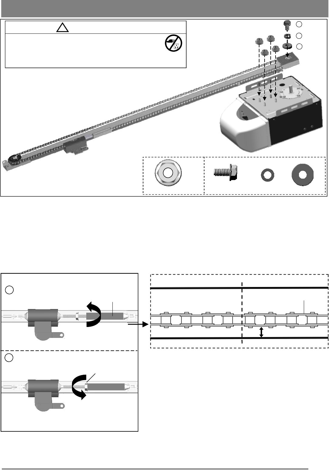
Tighten until...
2
Tighten nut
Flange Nut
Chain to Cable Connector
To Tighten the Chain:
Follow steps shown in Fig.2 to tighten the chain:
1. Turn the Chain-to-Cable Connector on the Trolley Shaft
until the chain is about 1/4” (6mm) above the base of the
rail. Compare with the illustration below.
2. Tighten the Flange Nut on Trolley Shaft against the Chain-to
-Cable Connector.
Notice
During operation, it is normal for the chain to appear loose when
the door is closed. If the chain returns to the position as shown
below when the door is opened, the chain is adjusted properly.
DO NOT re-tighten the chain.
When performing maintenance, always PULL the Emergency
Release to DISCONNECT the door from Opener before adjusting
the chain.
1/4” (6mm)
Base of Rail
Mid-point of rail assembly
Chain
Top of Rail
Actual Size
T-rail Assembly and Tensioning
Fig.1
! CAUTION
- DO NOT connect power until instructed.
- To prevent INJURY, keep hands and fingers away
from joints and possible sharp edges.
- Wear gloves when installing chain and cable.
2
3
4
1/4” Flange Nut x 4 Screw
Spring Washer Washer
To Assemble the Rail
Align the pre-assembled T-rail on the top of opener in the direction as shown in Fig.1.
Secure the T-rail to the opener firmly using 1/4” flange nut x 4.
Final Step to T-Rail Installation
Fasten the Screw(2) to the motor shaft with spring washer(3) and washer(4) in between.
Note: The chain or belt rail assembly comes pre-tensioned from the factory. If installing with the optional belt rail,
follow the same adjustment steps.
#10 - 24 x 1/2”
13
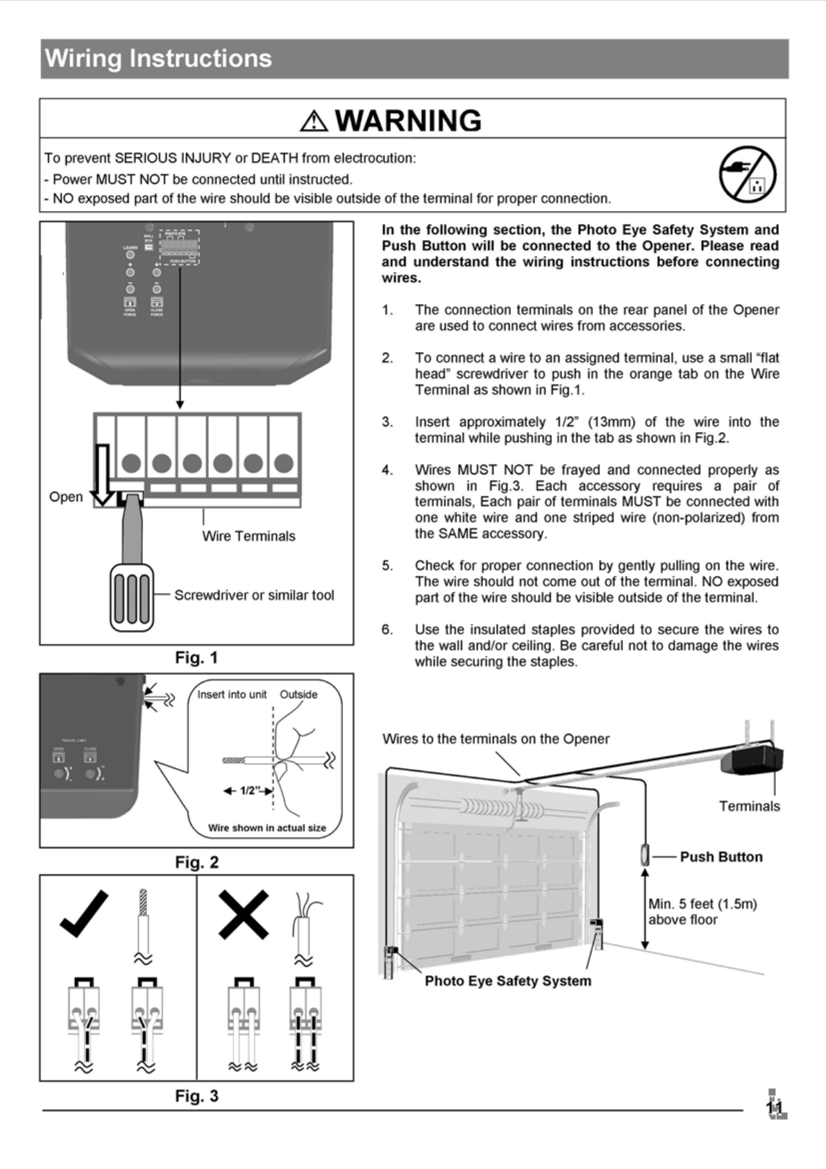
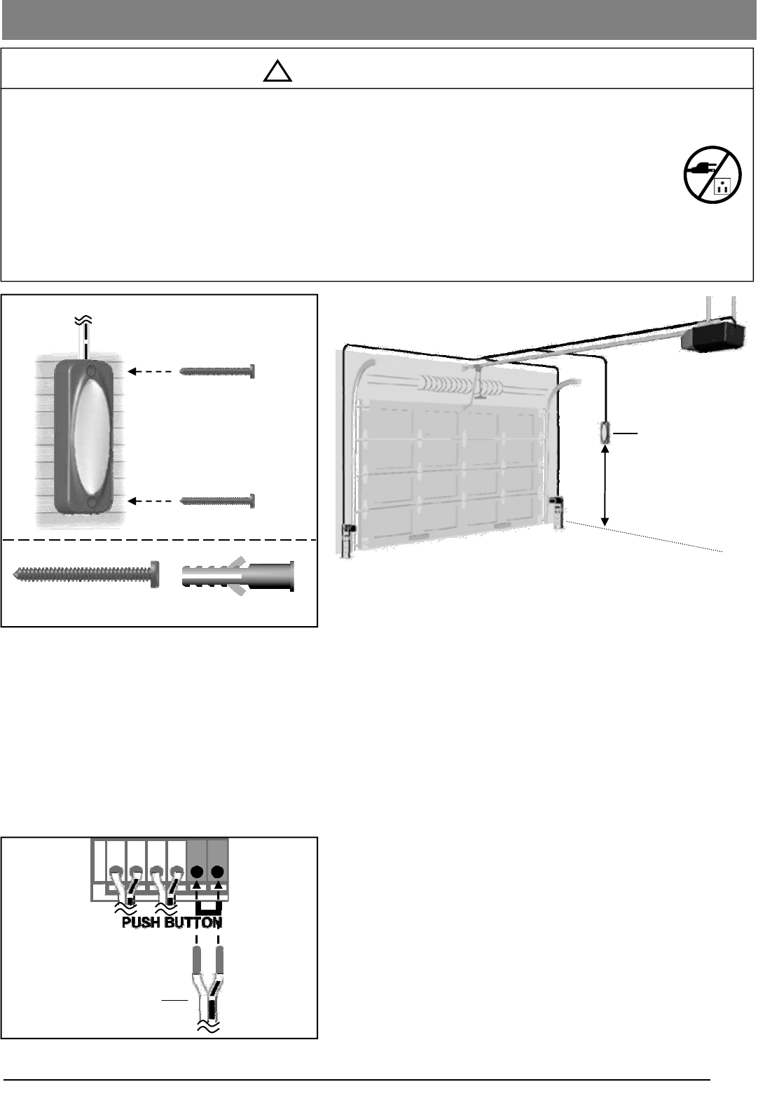
To Connect the Push Button to the Opener
Connect the pair of wires from the Push Button to the pair of
“PUSH BUTTON” terminals on the rear of the Opener. Refer to
Wiring Instructions on page 12 to ensure wires are properly
connected.
The Push Button is a wired, illuminated door control placed
inside your garage.
To install the Push Button:
1. Inside your garage, install Push Button within sight of the
door at a minimum height of 5 feet (1.5m) off the ground.
Ensure it is installed out of the reach of children and free
from the moving parts of the door and hardware.
2. Securely fasten it to a solid surface with # 6x1-3/8” screws
provided. If attaching to drywall or other hollow surface,
drill 3/16” holes and use the provided Drywall Anchors.
To prevent SERIOUS INJURY or DEATH from electrocution:
- Power MUST NOT be connected until instructed.
To prevent SERIOUS INJURY or DEATH from using the Push Button and a closing door:
- Install the Push Button within sight of the door at a minimum height of 5 feet (1.5m) above the floor.
Make sure it is out of the reach of children and moving parts of door and hardware.
- NEVER permit children to access the Push Button or Remote Controls.
- Operate the door ONLY when it is adjusted properly with no obstructions present and is in clear sight.
- ALWAYS keep a moving door in sight until it’s completely closed.
- NEVER cross the path of a moving door.
Push Button
Min. 5 feet (1.5m)
above floor
From Push Button
Connecting Push Button
! WARNING
Drywall Anchor
Screw #6 x1-3/8”
20
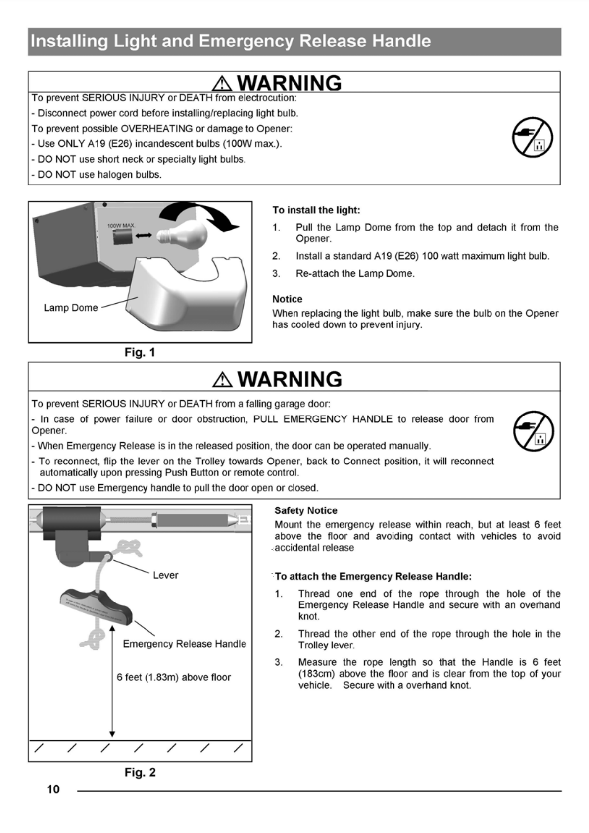
In case of a power failure or door obstruction, PULL
EMERGENCY Handle to release door from Opener.
To Disconnect Trolley for Manual Operation
With the door closed, pull down the emergency release Handle
to the DISCONNECT position. The door can be raised / lowered
manually.
To Re-connect Trolley
Pull the Handle toward the Opener so that the lever will flip up
to the CONNECT position. The Trolley will reconnect itself when
the Opener is activated or when the door is manually opened/
closed
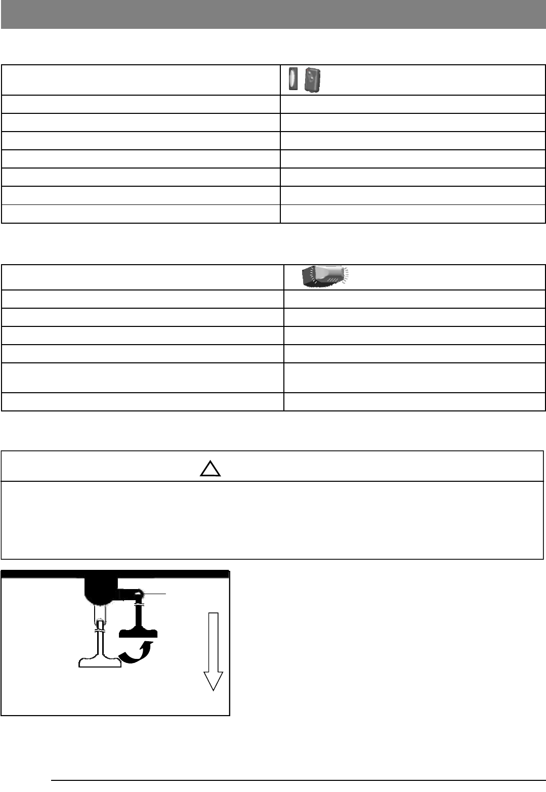
Operation / Condition Courtesy Light Response
Opener is initially plugged-in / Power restored Flashes 5 times
Upon Opener activation Turns on for 4-1/2 minutes and turns off automatically
“LEARN” button is pressed Turns on for 30 seconds
Remote Control / Keyless Entry PIN code accepted Flashes 5 times
The Photo Eye System is obstructed during door-closing or
door is obstructed during opening Flashes for 30 seconds (Re-align and clear obstruction)
Opener motor overheat (Thermal Protection) Flashes 5 times (Wait about 15 minutes to cool down)
Courtesy Light Responses
Manual Operation
Door status Activation using Push Button / Remote Con-
trol
Door at fully open / close position Door will move to fully close / open position
Door is closing Door will reverse
Door is opening Door will stop
Door is stopped as intended in partially open position Close
Door is obstructed while closing Door will reverse while flashing courtesy light
Door is obstructed while opening Door will stop
Door is fully opened and Photo Eye System is obstructed Door will not close
Door Status vs. Activation
Operating the Opener
! WARNING
To Prevent SERIOUS INJURY or DEATH:
- Use Emergency Release to disconnect Trolley ONLY when the door is CLOSED to prevent unexpected rapid falling in
case of a unbalanced / poor-conditioned door.
- Use Emergency Release ONLY when doorway is clear of persons and obstructions.
- DO NOT use Emergency Release to pull the door open or closed.
Lever
CONNECT
DISCONNECT
Pull to Disconnect
Flip to reconnect
21
Troubleshooting
Problem Possible Cause / Solution
Opener does not close and light flashes The Photo Eye may be obstructed, not properly aligned or installed,
check connection and alignment referring to pages 12 & 14.
Opener does not respond to Remote Control - Refer page 18 to reprogram Remote Control.
- Check Remote Control battery
Opener stops before reaching full open / close
position
Either the Travel Limit or Force is not properly adjusted, check
adjustment referring to pages 15-16. Conduct Safety Reverse Test
after ANY adjustment.
The door reverses unintentionally
- Make sure the Photo Eye Safety System is aligned and clear of
obstructions.
- Refer to page 4 to check the door balance
- Refer to page 16-18 to re-adjust the force
The door reverses upon touching the floor and
the courtesy light flashes
Refer to page 15 to decrease Close Limit by 1/4 turn until door stops
as intended at the fully closed position. Conduct Safety Reverse Test
after ANY adjustment.
The courtesy light flashes 5 times and the
Opener does not start Opener motor overheat, please wait about 15 minutes and retry.
The Opener does not close the door and the
green LED on the Photo Eyes flashes The Photo Eye Safety System is misaligned or obstructed, refer to
page14 for proper alignment.
The Opener is working properly but the courtesy
light does not turn on Replace light bulb (A19 incandescent Max.100W).
The courtesy light does not turn off Defective Logic Board.
Schedule Maintenance
Once a month Door balance test, refer to page 4.
Safety reverse test, refer to page 17.
Twice a year Check chain tension ( refer to page 5 for adjustment if necessary).
Once a year
- Limit and Force adjustment may be necessary due to weather conditions.
Refer to pages 15-16 for adjustment. Conduct Safety Reverse Test after ANY
adjustments.
- Lubricate door rollers, bearings and hinges. The Opener is permanently
lubricated, DO NOT lubricate or grease the Opener, rail or door tracks.
Maintenance
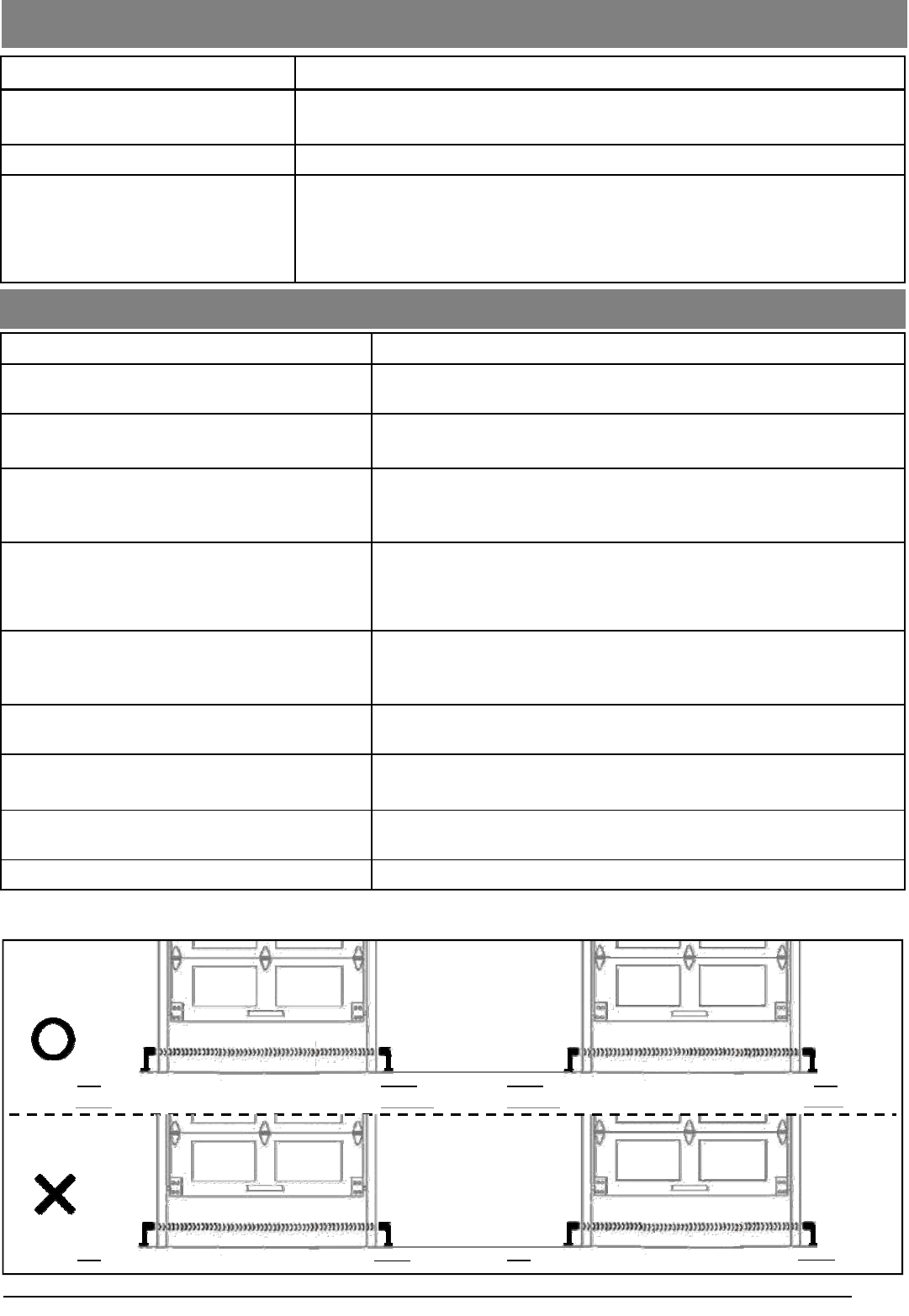
Red LED Green LED
Green LED
Green LED Red LED Green LED
Red LED
Red LED Green LED Red LED
Note: If installing operators on two doors in the same garage, to ensure proper operation, Photo Eyes should
be aligned as below:
Green LED Red LED
22
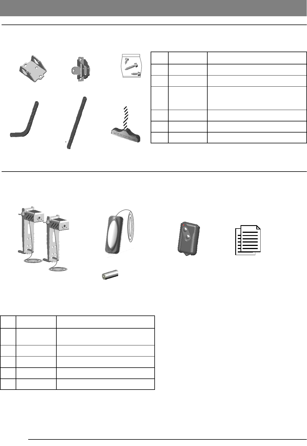
Installation Parts
23
4 5 6
1
Repair Parts
Item Part No. Name / Description
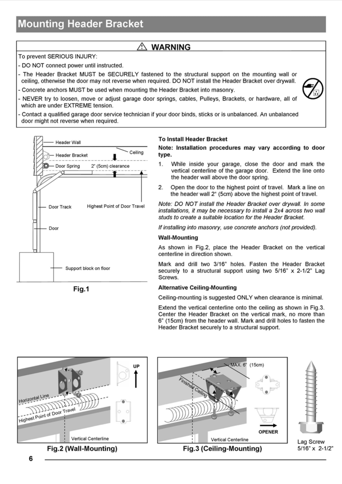
1GUAT-027 Header Bracket
2GUAT-022 Door Bracket
3GUAT-023 Hardware Bag
(Installation hardware shown on P.3)
4GUAT-024 Curved Door Arm
5GUAT-025 Straight Door Arm
6GUAT-026 Emergency Release Handle & Rope
Accessories
Item Part No. Name / Description
1GUAT-201 Photo Eye Safety System
(Emitter + Sensor with Brackets)
2GUAT-202 Push button
3GUAT-203 12V alkaline battery
4R2BCC Remote Control
5GUAT-205 Owner’s manual
1
2
3
5
4

Manufacturer hereby warrants:
1. Garage Door Operators to be free from defects in material and workmanship for a period of five (5) years for motors and
one (1) year for Electronics and Mechanics from date of purchase, if installed by an authorized reseller, otherwise if in-
stalled by the purchaser one (1) year will apply.
2. Garage Door Operators (Commercial and Industrial Application) to be free from defects in material and workmanship for
a period of three (3) months from date of purchase.
3. Where the garage door operator has been returned to the manufacturer for Warranty repairs, all costs incurred in the
return will be paid for by the purchaser. If in the opinion of the manufacturer the product is faulty, all defective parts will
be replaced at no charge to the purchaser.
4. Proof of purchase must be given to the manufacturer at time of Warranty claim.
5. The manufacturer reserves the right to modify any existing or future products without incurring any obligation to incor-
porate such modification to products already manufactured or to which this Warranty may relate.
6. Warranty only applies if this product has been installed to the Manufacturers recommendation
7. This Warranty does not apply to any defect, loss or damage arising or caused directly or indirectly by or as a result of :
(i) Any defect (including detects in component parts or accessories) arising from or attributable to the failure to carry
out normal preventive maintenance or adjustment itself.
(ii) To any additional damage or deterioration arising from attributable to the operation of the Operator after it is
known to be defective.
8. Exclusions to Warranty Period:
(i) Repair or Warranty Work - three (3) month
9. Not included in Warranty:
(i) Batteries.
(ii) Fuses.
(iii) Light bulbs.
(iv) Sensitivity adjustment.
(v) Handheld Remote Controls and receiver range.
10. Note : All Warranties will be void subject to:
(i) Water damage and condensation.
(ii) Power supply black out or surge.
(iii) Act of God.
(iv) Modification or adjustment by unauthorized persons.
(v) Any interference from radio (including citizen band radios or and other electronic device)
(vi) Preventative maintenance and regular servicing not undertaken.
(vii) Account not paid in full by the purchaser.
11. Subject only to the provisions of the Trade practices Act and any legislation of the State or Territory wherein the oper-
ators of the Manufacturer have been sold or installed (which may confer certain rights on consumers of goods and
those rights by such legislation may be rendered incapable of exclusion) this Warranty supersedes and excludes all
representations, warranties and conditions whether expressed or implied by law and the Manufacturer shall have no
liability or otherwise than herein provided for any loss and damage (including consequential loss and damage, loss of
use or profits) by reasons of delay, defective or faulty materials or workmanship, negligence or any act, matter or thing
done permitted or omitted to be done by the Manufacturer.
WARRANTY
THIS WARRANTY FORM SHOULD BE COMPLETED AT TIME OF INSTALLATION
This Warranty Form should be retained by the purchaser at all times and produced with the purchase docket by the Pur-
chaser as proof of the purchase date.
PURCHASER’S NAME:
PURCHASER’S ADDRESS:
INSTALLED BY:
INSTALLER’S ADDRESS:
INSTALLER’S SIGNATURE:
SERIAL NUMBER OF THE OPERATOR:
GUARDIAN SERVICE
Your operator has been installed by a professional installation specialist. If service information is required please contact
the installing company or your local Guardian dealer. Look for your Guardian dealer online, in the yellow pages or call our
service number for a dealer near you.
Service number : 1-424-272-6998
Please have the following information when you call:
·Model number of the operator
·Serial number of the operator--located on the bar code label on top of the opener, above the adjustment buttons
WARRANTY
GARAGE DOOR OPERATORS

FCC Warning:
Any Changes or modifications not expressly approved by the party responsible for compliance could void the user’s
authority to operate the equipment.
Note: This equipment has been tested and found to comply with the limits for a Class B digital device, pursuant to part
15 of the FCC Rules. These limits are designed to provide reasonable protection against harmful interference in a
residential installation. This equipment generates, uses and can radiate radio frequency energy and, if not installed
and used in accordance with the instructions, may cause harmful interference to radio communications. However,
there is no guarantee that interference will not occur in a particular installation. If this equipment does cause harmful
interference to radio or television reception, which can be determined by turning the equipment off and on, the user is
encouraged to try to correct the interference by one or more of the following measures:
—Reorient or relocate the receiving antenna.
—Increase the separation between the equipment and receiver.
—Connect the equipment into an outlet on a circuit different from that to which the receiver is connected.
—Consult the dealer or an experienced radio/TV technician for help.