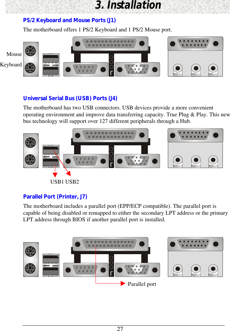
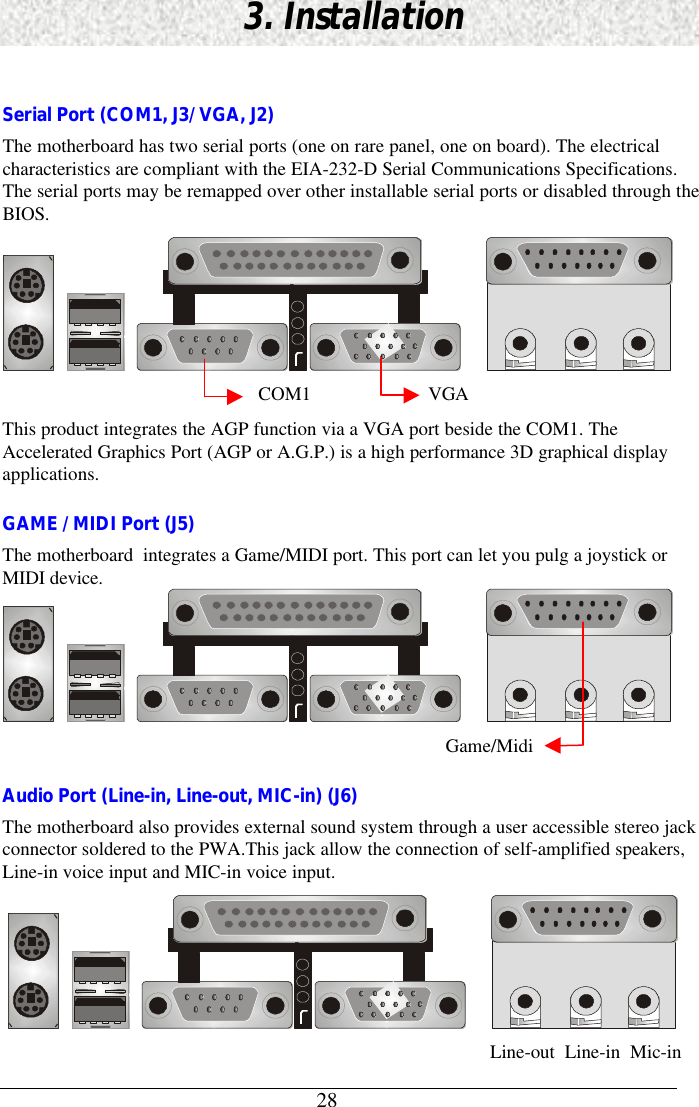
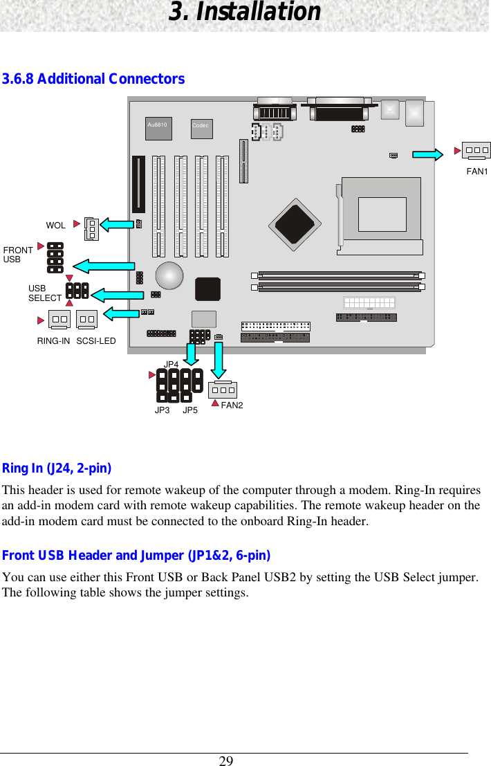
GVC EPIQ-742 EPIQ Computer User Manual IN810P6
GVC International U.S.A., Inc. EPIQ Computer IN810P6
UserManual.wiki
>
GVC
>
EPIQ 742 User Manual
MANUAL
Navigation menu
Upload a User Manual
Namespaces
Wiki Guide
HTML
PDF
Info
Views
User Manual
Discussion / Help
Navigation


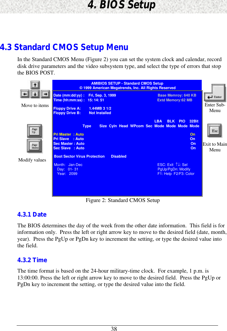

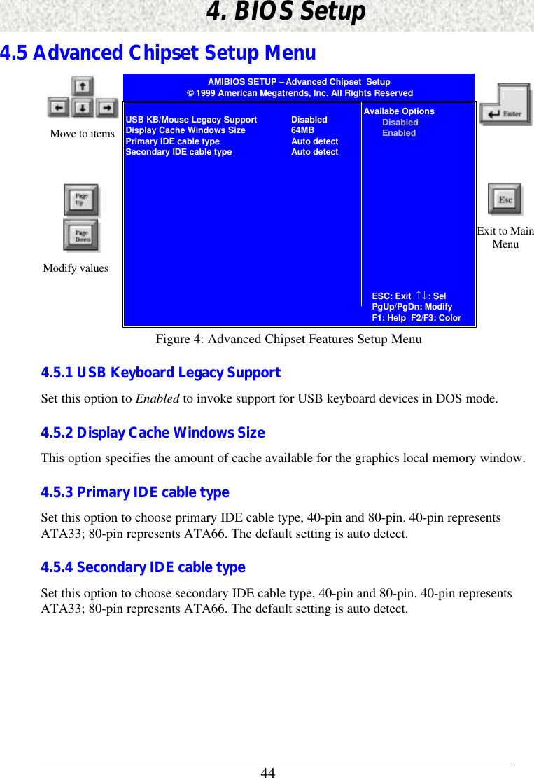
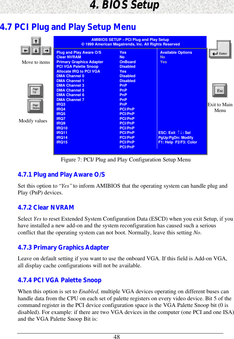
![454. BIOS Setup4.6 Power Management Setup MenuAMIBIOS SETUP – Power Management Setup© 1999 American Megatrends, Inc. All Rights ReservedMove to items Enter Sub-MenuModify valuesPower Management/APMVideo Power Down ModeHard Disk Power Down ModeSuspend Time OutKeyboard & PS/2 Mouse AccessFDC/LPT/COM Ports AccessMidi Port AccessPrimary Master IDE AccessPrimary Slave IDE AccessSecondary Master IDE AccessSecondary Slave IDE AccessPIRQ[A] IRQ ActivePIRQ[B] IRQ ActivePIRQ[C] IRQ ActivePIRQ[D] IRQ ActivePower Button ModeRestore on AC/Power LossResume On Ring HeaderResume On LAN HeaderPCI Slot PME Function SupportResume On RTC AlarmRTC Alarm DateRTC Alarm HourRTC Alarm MinuteRTC Alarm SecondEnabledSuspendSuspendDisabledMonitorIgnoreIgnoreMonitorIgnoreIgnoreIgnoreIgnoreIgnoreIgnoreIgnoreInstant OffPower OffDisabledDisabledDisabledDisabled15123030Available OptionsNOYesSC: Exit ↑↓: SelPgUp/PgDn: ModifyF1: Help F2/F3: ColorExit to MainMenuFigure 6: Power Management Setup Menu4.6.1 Power Management/APMSet this option to Enabled to invoke the chipset power management and APM (AdvancedPower Management) features.4.6.2 Video Power Down ModeThis option specifies the power state that the video subsystem enters when AMIBIOS placesit in a power saving state after the specified period of display inactivity has expired.4.6.3 Hard Disk Power Down ModeThis option specifies the power conserving state that the hard disk drive enters after thespecified period of hard drive inactivity has expired.4.6.4 Suspend Time OutThis option specifies the length of a period of system inactivity while in Standby state. Whenthis length of time expires, the computer enters Suspend power state.](https://usermanual.wiki/GVC/EPIQ-742/User-Guide-124214-Page-45.png)
![464. BIOS Setup4.6.5 AccessWhile choosing Monitor, an event occurring on each device listed below for monitoring:Ø Keyboard and PS/2 AccessØ DFC/LPT/COM Ports AccessØ MIDI Ports AccessØ Primary/Secondary Master IDE AccessØ Primary/Secondary Slave IDE AccessØ PIRQ[A]-[D] IRQ Active4.6.6 Power Button ModeThis option specifies how the power button mounted externally on the computer chassis isused. The settings are:Setting DescriptionOn/Off Pushing the power button turns the computer on or off.Suspend Pushing the Power button places the computer in Suspendmode or Full On power mode.4.6.7 Restore on AC/Power LossThis option is used to reboot system after power has been interrupted. Power Off leaves thesystem off and Last State reboots the system.4.6.8 Resume On Ring HeaderThis option allows either settings of “Enabled” or “Disabled” for powering up the computerwhen the modem receives a call while the computer is soft-off mode.Note: The computer can not receive or transmit data until the computer and applications arefully running, thus connection can not be made on the first try. Turning an external modemoff and then back on while the computer is off causes an initialization string that will alsocause the system to power on.4.6.9 Resume On LAN HeaderWake-On-Lane allows your computer to be booted from another computer via a network bysending a wake-up frame or signal.](https://usermanual.wiki/GVC/EPIQ-742/User-Guide-124214-Page-46.png)