GVC F1156IVR10 Data Fax Modem User Manual R181078000CONTENT
GVC Corporation Data Fax Modem R181078000CONTENT
GVC >
USERS MANUAL

High Performance
V.90/K56flex/V.34+/V.42bis
56000BPS
Plug & Play Internal
Data/Fax/Modem
User's Manual
Contents
Section One - Introduction ........................... 1
Section Two - Installation Guide .................. 1
Section Three - AT Command Set ............... 5
Section Four - S Registers........................10
Appendix A Specifications ........................ 10
Appendix B Installations ..........................11
F-1156IV/R10

The information contained in this manual has been
validated at the time of this manual's production.
The manufacturer reserves the right to make any
changes and improvements in the product de-
scribed in this manual at any time and without
notice. Consequently the manufacturer assumes
no liability for damages incurred directly or indi-
rectly from errors, omissions or discrepancies be-
tween the product and the manual.
All registered trademarks are the property of their
respective owners.
Copyright © 1997 All rights reserved. No reproduction
of this document in any form is permitted without prior
written authorization from the Manufacturer.

1
1.Turn off power to Windows 98 PC, remove PC cover,
insert card to an available PCI slot,close cover,turn on
power.
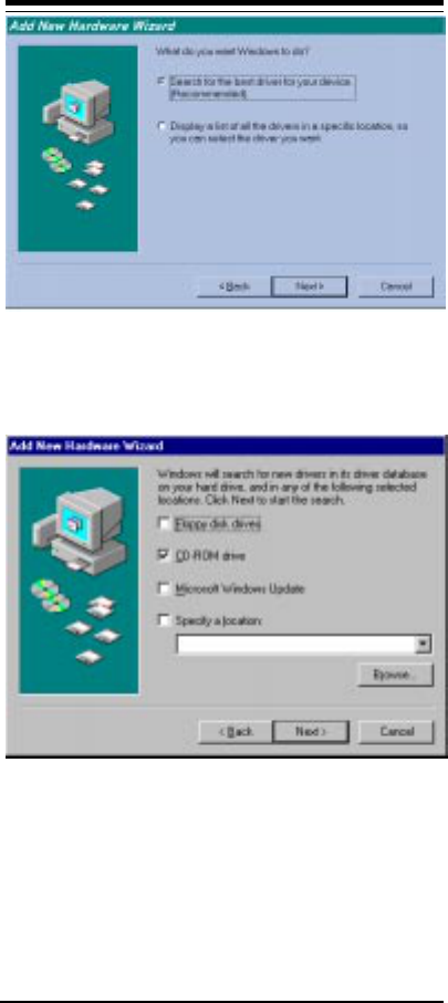
2.When Windows 98 loads,it will detect the new hard-
ware and ask for a driver. the following window should
appear.
3.Click Next and you should see:
Section One - Introduction
This 56 kbps* Plug and Play FAX/Data Modem
connects your computer to all popular high speed mo-
dems available today. Its incorporates "V.90/K56Flex"
(56Kbps)
technology to provide increased download
speeds using regular telephone lines. The modem incor-
porates Plug and Play for ease of installation.
This manual describes the AT commands and S-
registers so that your system can be customized for a
particular operating environment.
*Note: K56flex is capable of downloading at 56kbps.
However, current FCC regulations limit its speeds to
53Kbps.
Section Two - Installation Guide
2
4.Select "Search for the best driver for your device"
Option. Click Next and you should see:
5.Insert the CD-ROM that comes with your Modem into the
CD-ROM drive. Make sure the CD-ROM drive check box
is checked. Leave all other check boxes blank. Click Next
and you should see:

3
6.Click Next and you should see the following.
7.Wait until Windows 98 finishes copying all the required
files.

4
8.When you see the above window, Windows 98 has
already finished copying all the files. Click Finish and you
should see the following window.
9.Your Modem is now installed in Windows 98.

5
Section Three - AT Command Set
3.1 Commands
Commands are accepted by the modem while it is
in Command Mode. Your modem is automatically in Com-
mand Mode until you dial a number and establish a
connection. Commands may be sent to your modem from
a PC running communication software or any other
terminal devices.
Your modem is capable of data communication at
rates of: 300, 1200, 2400, 4800, 9600, 14400, 19200,
28800, 38400, 57600, and 115200 bps. Make sure your
COM port baud rate in your communications software is
set to one of the above speeds.
3.2 Command Structure
All commands sent to the modem must begin with
AT and end with ENTER. All commands may be typed
in either upper or lower case, but not mixed. To make the
command line more readable, spaces may be inserted
between commands. If you omit a parameter from a
command that requires one, it is just like specifying a
parameter of 0. Example:
ATH [ENTER]
This command causes your modem to hang up.
3.3 Basic AT Commands
In the following listings, all default settings are
printed in bold text.
Command Function
AManually answer incoming call.
A/ Repeat last command executed. Do not
precede A/ with AT or follow with
ENTER.
D_ 0 - 9, A-D, # and *
L last number redial
P pulse dialing
T touch-tone dialing
W wait for second dial tone
, pause
@ wait for five seconds of silence

6
! flash
; return to Command Mode after dialing
E_ E0 Commands are not echoed
E1 Commands are echoed
+++ Escape Characters Switch from Data
Mode to Command Mode
H_ H0 Force modem on-hook (hang up)
H1 Force modem off-hook (make busy)
I_ I0 Reports product code
I1 Reports Pre-Computed checksum
I2 Internal memory test
I3 Firmware ID
I4 Reports data pump model and internal
code revision
L_ L0 Low speaker volume
L1 Low speaker volume
L2 Medium speaker volume
L3 High speaker volume
M_ M0 Internal speaker off
M1 Internal speaker on until carrier
detected
M2 Internal speaker always on
M3 Internal speaker on until carrier detected
and off while dialing
O_ O0 Return to Data Mode
O1 Return to Data Mode and initiate an
equalizer retrain
PSet Pulse dial as default
Q_ Q0 Modem sends responses
Q1 Modem does not send responses
Sr? Read and display value in register r.
Sr=n Set register r to value n (n = 0-255).
T Set Tone Dial as default
V_ V0 Numeric responses
V1 Word responses
X_ X0 Hayes Smartmodem 300 compatible
responses/blind dialing.
X1 Same as X0 plus all CONNECT responses/
blind dialing
X2 Same as X1 plus dial tone detection
X3 Same as X1 plus busy detection/blind
dialing

7
X4 All responses and dial tone and
busy signal detection
Z_ Z0 Reset and retrieve active profile 0
3.4 Extended AT Commands
&C_ &C0 Force Carrier Detect Signal High (ON)
&C1 Turn on CD when remote carrier is
present
&D_ &D0 Modem ignores the DTR signal
&D1 Modem returns to Command Mode after
DTR toggle
&D2 Modem hangs up, returns to the
Command Mode after DTR toggle
&F_ &F Recall factory default configuration
&G_ &G0 Guard tone disabled
&G1 Guard tone disabled
&G2 1800 Hz guard tone
&P_ &P1 Select 33 ratio M/B at 10pps
&P3 Same as &P1 setting but at 20 pulses per
second
&V &V0 Displays Active and Stored Profiles
&W_ &W0 Stores the active profile as Profile 0
%E_ %E0 Disable auto-retrain
%E1 Enable auto-retrain
+MS? Displays the current Select Modulation
settings
+MS=? Displays a list of supported Select
Modulation options
+MS=a,b,c,d,e,f Select modulation. a,b,c,d,e,f
default=V.90,1,75,33600,
75,56000.Parameter¡§a¡¨specifies the
modulation protocol desired where:
B103=Bell103,B212=Bell212,
V21=V.21,V22=V.22,V22B=V.22bis,
V23C=V.23,V32=V.32,V32B=V.32bis,
V34=V.34,K56FLEX=K56FLEX,V.90=V.90.
Parameter¡§b¡¨specifies automode
operations where=automode disabled,
1=automomod enabled.Parameter
¡§c¡¨specifies the minimum connected
speed of the transmit direction.
Parameter¡§d¡¨specifies the maximum
connected speed of the transmit

8
direction. Parameter¡§e¡¨specifies the
minimum connected direction.Parameter
¡§f¡¨specifies the maximum connected
direction.
3.5 MNP/V.42/V.42bis Commands
+ES? Displays the current Error Control
and Sychronous Mode Selection
settings.
+ES=? Displays a list of supported Error
control and Sychronous Mode
Selection options.
+ES=a,b,c Error Control and Sychronous Mode
Selection where: a=1-4, b=0,2-4, c=1
,2,4,5,6. a,b,c default=3,0,2.
Parameter "a" specifies the initial
requested mode of operation where
1=Normal Mode, 2=V.42 without
Detection Phase, 3=V.42 with
Detection Phase, 4=MNP.Parameter
"b" specifies the acceptable fallback
mode of operation where:0=LAPM,
MNP, or Normal Mode error control
optional, 2=LAPM or MNP error
control required, 3=LAPM error
control required, 4=MNP error control
required. Parameter "c" specifies the
acceptable fallback mode of operation
where:1=Normal Mode, 2=LAPM,
MNP,or Normal Mode error control
optional, 4=LAPM or MNP error
control required, 5=LAPM error control
required, 6=MNP error control
required.
+ER? Displays the current Error control
reporting settings.
+ER=? Displays a list of supported Error
control reporting options.
+ER=n n=0 Error control reporting disabled.
n=1 Error control reporting enabled.
(Default.)
+DS? Displays the current Data
Compreesion settings.

9
+DS=? Displays a list of supported Data
compression options.
+DS=a,b,c,d Data Compressin. a,b,c,d default
=3,0,2048,32.Paramerer¡§a¡¨specifies
the desired dierction(s) of operation
of operation of the data comperession
function where:0=no compression,
3=both. Parameter ¡§b¡¨ specifies
whether or not the modem should
continue to operate if the desired
result is not obtained where:0= Do
not disconnect if V.42bis not
negotiated by the remote modem as
specifies in a.Parameter¡§c¡¨the
maximum number of dictionary entries
(2048 entries) which should be
negotiated.Parameter¡§d¡¨
specifies the maximum string length
(32bytes) to be negotated. (V.42bis
P2)
+DR? Displays the current Data
Compression Reporting setting.
+DR=? Displays a list of supported Data
Compression reporting options.
+DR=n n=0 Data Compression reporting disabled.
n=1 Data Compression reporting enabled.
%E_ %E0 Disable Line Quality Monitor, Auto-
Retrain,and Auto-Rate Renegotiation.
%E1 Enable Line Quality Monitor,Auto-
retrain,and Auto-Rate Renegotiation.
%L Line signal Level
%Q Line Signal Quality
3.6 Fax Class 1 Commands
+FAE=n Data/Fax Auto Answer
+FCLASS=n Service Class
+FRH=n Receive data with HDLC framing
+FRM=n Receive data
+FRS=n Receive silence
+FTH=n Transmit data with HDLC framing
+FTM=n Transmit data

10
+FTS=n Stop transmission and wait
Section Four - S Registers
Your modem has 13 registers, designated S0 through
S29. Table 3-1 shows the registers, their functions, and
their default values. Some registers can have their values
changed by commands. If you use a command to change
a register value, the command remains in effect until you
turn off or reset your modem. Your modem then reverts
to the operating characteristics specified in its non-
volatile memory. Refer to Section 3 for information on how
to use the AT commands to manipulate the S registers.
Table 4-1 S - Registers
Register Function Range/units Default
S0 Auto-answer Ring 0-255 /rings 0
S1 Ring Counter 0-255 /rings 0
S2 Escape Character 0-255 /ASCII 43
S3 Line Terminaion Character 0-127 /ASCII 13
S4 Response Formattimg 0-127 /ASCII 10
Character
S5 Command Line Editing 0-32 /ASCII 8
Character
S6 Wait Time for Dial Tone 2-255 /seconds 2
S7 Wait Time for Carrier 1-255 /seconds 50
S8 Pause Time for Dial Delay 0-255 /seconds 2
Modifier
S10 Carrier Loss Diseconnect 1-255 /0.1 second 14
Time
S11 DTMF Tone Duration 50-255 /0.001seconds 95
S12 Escape Prompt Delay 0-255 /0.02 second 50
S29 Flash Dial Modifier Time 0-255 /10millisconds 70
Appendix A - Specifications
Communication Std: V.90,K56flex (56k model) for
highest Internet connection
rates, 33.6kbps,31.2kbps,V.34,
V.32bis,V.22bis,V.22A/
B,V.23,and V.21;Bell 212A and
103
Data Compression: V.42bis/MNP5
FAX Group: Group 3 send and receive and
T.30 protocol.
FaX Correction: EIA/TIA 578 Class 1, Class 1.0
(T.31) fax

11
Error Correction: V.42/MNP2,3,4
Other Function: Plug and Play ,ACPI Power
management compliantly .
Host Interface: Plug and Play PCI bus interface.
Transmit Level: -11dBm
Receiver Sensitivity: -32dBm(V.34);-36dBm(all other
protocols)
DTE Speeds: 300-115200bps
Operating Temperature: -0 - + 55 degrees C
Storage Temperature: -50 - + 70 degrees C
Appendix B - Specifications
Installation Restart the computer after plugging in the
modem. When Windows detects the mo-
dem, the message "This wizard will
compiet the installation of:PCI Serial Con-
troller" is displayed.
Click "next" other location",then enter then
path to the drivers, then click "OK".
Windows disp;ays "Windows found the
folloewing updated driver for this
device:Rockwell PCI Modem Enumera-
tor".
Click "Finish" and Windows displays
"Please insert the disk labeled WIN95
Installion Disk, and then click OK."
Click "OK" and enter the path of the drivers
again. Insataiition should then complete
automaticcally.
Uninstalling Click on the "Add/Remove Programs"icon
under START>SETTINGS>CONTROL
PANEL.
Select "Rockwell HCF 56k Modem" under
the INSTALL/UNIINSTALL tab and click the
"ADD/REMOVE" button.When completed
successfully, the INF files, VXDs, and
registry entries caused by the modem
installation are deleted fromthe hard disk.
The system should be rebooted at this
point if a modem is to be reinstalled.

12
Forderal Communications Commission (FCC)
Statement
This Equipment has been tested and found to comply with
the limits for a Class B digital device,pursuant to Part 15
of the FCC rules. These limits are designed to provide
reasonable protection against harmful interference in a
residential installation. This equipment generates, uses
and can radiate radio frequency energy and, if not
installed and used in accordance with the instructions,may
cause harmful interference to radio communications.
However, there is no guarantee that interference will not
occur in a particular installation. If this equipment does
cause harmful interference to radio or television recep-
tion, which can be determined by turning the equipment
off and on, the user is encouraged to try to correct the
interference by one or more of the following measures:
- Reorient or relocare the receiving antenna.
- Increase the separation between the equipment and
receiver.
- Connect the equipment into an outlet on a different from
that to which the receiver is connected.
- Consult the dealer or an experienced radio/TV techni-
cian for help.
This device complies with Part 15 of the FCC Rules.
Operation is subject to the following two conditions: (1)
this device may not cause harmful interference, and (2)
this device must accept any interference received, in-
cluding interference that may cause undesired operation.