Gaggia Accademia Service Manual User
2015-12-30
User Manual: Gaggia Accademia Service Manual
Open the PDF directly: View PDF ![]() .
.
Page Count: 63
All parts of this document are the property of Saeco International Group.
All rights reserved. This document and all the information herein is provided without liability deriving
from any errors or omissions. Furthermore, no part may be reproduced, used or collected, except where
VSHFL¿FDXWKRULVDWLRQKDVEHHQSURYLGHGLQZULWLQJRUWKURXJKDFRQWUDFWXDODJUHHPHQW
Rev. 00 / March 2010
Service Manual
Revision 00 March 2010

Page
1. Introduction
1.1 Documentation required 1
1.2 Tools and equipment required 1
1.3 Material 1
1.4 Safety warnings 1
1.5 Accademia Range 2
1.6.1 External machine parts 3
1.6.2 Internal machine parts 4
7HFKQLFDOVSHFL¿FDWLRQV
7HFKQLFDOVSHFL¿FDWLRQV
2.2 Machine parameters and performance 2
3. User instructions
3.1 Customer and programming menu 1
3.2 Machine indications 2
3.3 Operation, cleaning and maintenance 3
4. Operating logic
4.1. Water circuit 1
4.2 Frother valve assembly 2
4.2.1 General carafe assembly 2
4.3 Multi-way valve 4
4.4 Coffee cycle 5
4.5 Single microswitch 6
4.6 Temperature sensor (adjustment) 6
4.7 Coffee grinder 7
4.8 Detection of coffee bean absence,
dose adjustment, blocked coffee grinder 7
4.9 Auto-learning dose (SAS) 8
4.10 SBS 9
4.11 Water level detection in the tank 10
4.12 Water level detection in the drip
tray 10
4.13 Descaling request 11
$QWLVFDOH¿OWHU
Contents
GAGGIA Rev. 00 / March 2010 ACCADEMIA

Contents
Page
5. Troubleshooting
5.1. Test mode 1
5.2 Diagnosis mode 6
5.3 Error messages 12
6. Standard inspections
6.1 Repair schedule 1
6.2 Service schedule 1
6.3 Final inspection 2
7. Disassembly
7.1 Outer elements 1
7.2 Coffee grinder 2
7.3 Grinder blades 3
7.4 Coffee grinder adjustment 4
7.5 Steam pump 5
7.6 Coffee pump 5
7.7 Flow meter 5
7.8 Power board 6
7.9 Steam boiler 6
7.10 Coffee boiler 6
7.11 Gearmotor 7
7.12 Frother valve assembly 8
7.13 Dispenser assembly 8
7.14 Steam pipe assembly 9
7HÀRQSLSHVXSSRUWDQGFDUDIH¿WWLQJDVVHPEO\
7.16 Carafe board general assembly 10
7.17 CPU board, display and front panel 10
7.18 Oetiker clamps 12
8. Notes
9. Water circuit diagram
10. Electrical diagram
GAGGIA Rev. 00 / March 2010 ACCADEMIA

GAGGIA Rev. 00 / March 2010 ACCADEMIA
CHAPTER 1
INTRODUCTION
ACCADEMIA 01 INTRODUCTION
GAGGIA Rev. 00 / March 2010 Page / 04
1.1 Documentation required
The following documentation is required for repairs:
,QVWUXFWLRQERRNOHWRIWKHVSHFL¿FPRGHO
7HFKQLFDOGRFXPHQWDWLRQRIWKHVSHFL¿FPRGHOGLDJUDPVH[SORGHGGUDZLQJV
1.2 Tools and equipment required
Besides standard equipment, the following tools are required:
Qty. Description Notes
1 Screwdriver Torx T 8 - T 10 - T 20
1 Pliers for Oetiker clamps
1 AC - DC - Vdc tester
1 Digital thermometer Scale limit > 150°C
1 SSC (Saeco Service Center) Programmer
(for programming and diagnosis mode)
1.3 Material
Description Notes
Thermal paste Heat resistance > 200°C
Descaler Gaggia descaler
Degreaser Personal choice
Silicone grease Safe to use with food
1.4 Safety warnings
It is recommended to consult the technical manual of the machine before implementing any
operation.
Comply with all applicable standards relating to the repair of household appliances.
Always disconnect the power plug from the mains before beginning repairs on the machine.
6LPSO\WXUQLQJRIIWKHPDLQVZLWFKLVQRWVXI¿FLHQWO\VDIHWRSUHYHQWHOHFWULFDOGLVFKDUJHV.
This household appliance is rated as insulation class I.
On completion of the repairs, insulation and dielectric rigidity tests must be performed.
01
ACCADEMIA 01 INTRODUCTION
GAGGIA Rev. 00 / March 2010 Page / 04
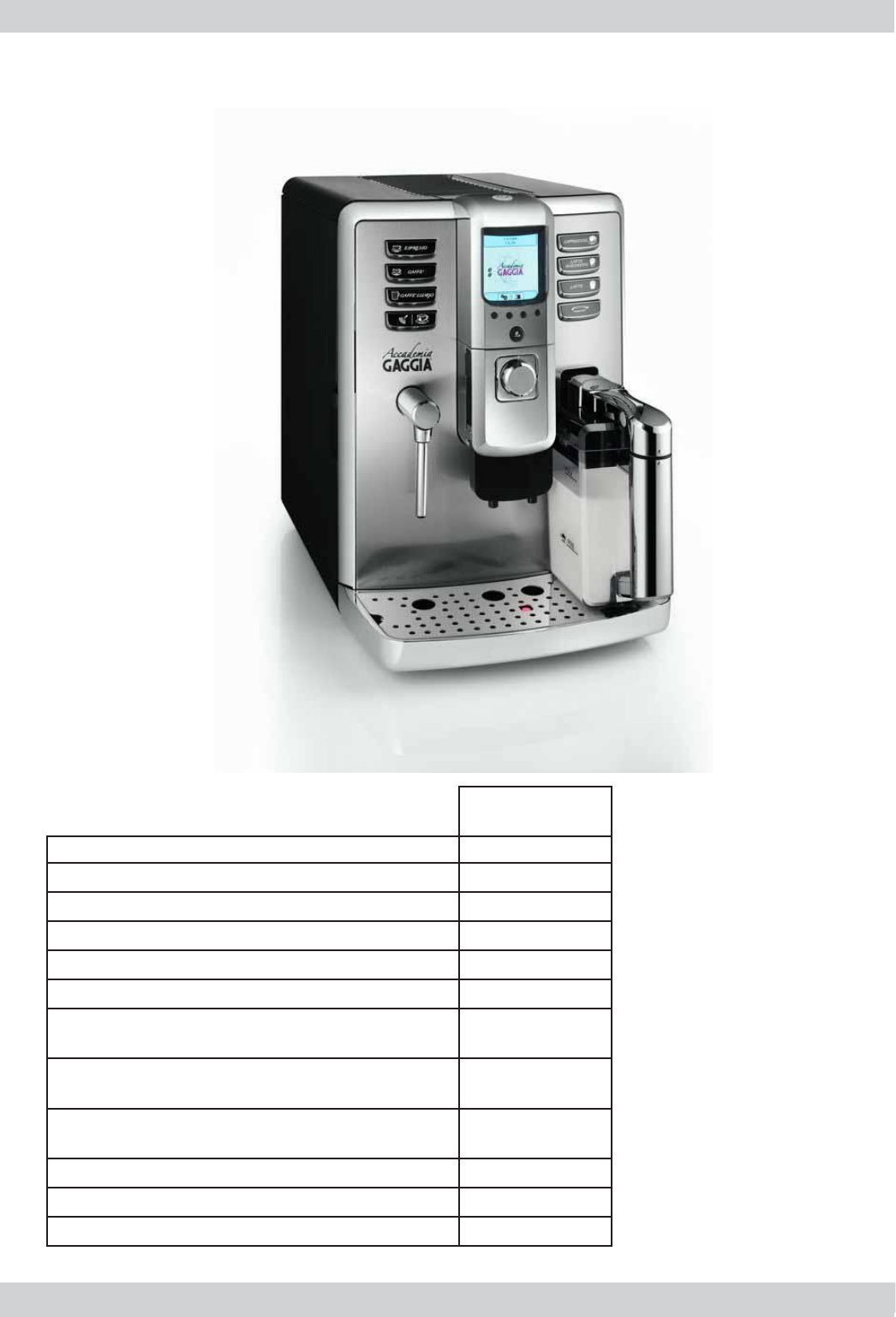
1.5. Accademia Range
Accademia
Display interface X
With painted stainless steel parts X
Milk carafe X
Clean (automatic milk circuit washing) X
Automatic dosing (SAS) X
Cup heater X
Quantity of dispensed coffee saved in
memory X
Quantity of dispensed milk saved in
memory X
Automatic shutdown
(after 60' inactivity) X
SBS X
Compartment for ground coffee X
Automatic descaling cycle X
02
ACCADEMIA 01 INTRODUCTION
GAGGIA Rev. 00 / March 2010 Page / 04
03
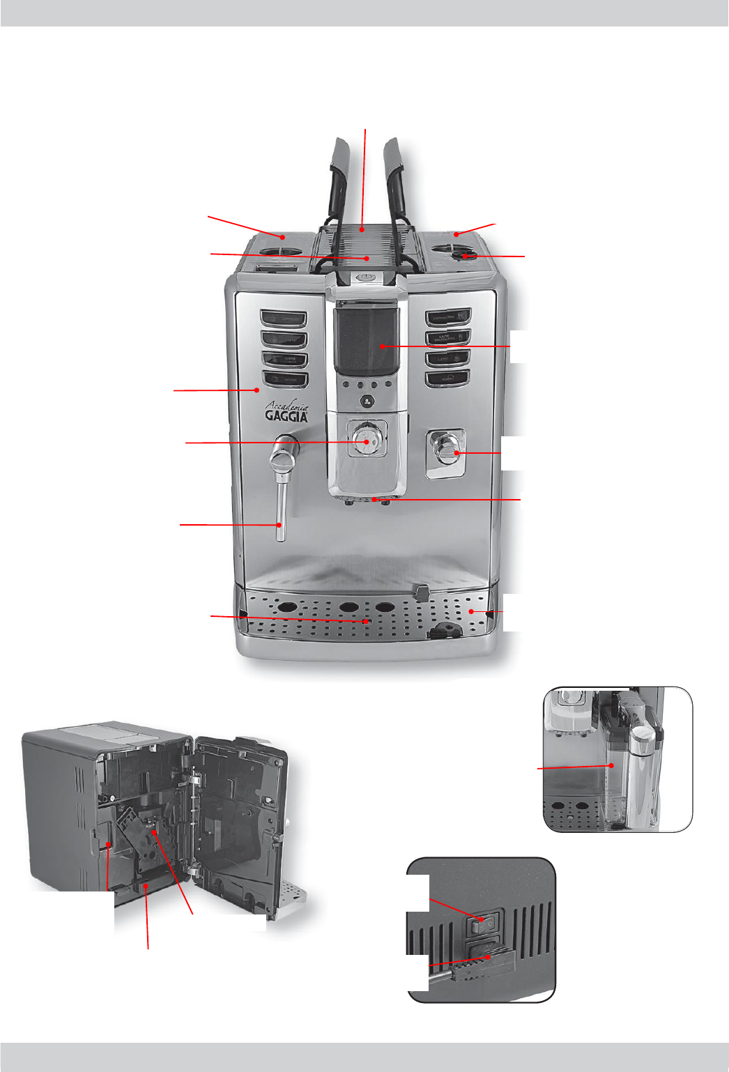
Cup heater plate
Coffee bean
container with lid
Grinding level
adjustment
Control
panel
Milk container
connector
Dispenser
Drip tray+grille
Water tank
Compartment for
pre-ground coffee
Service
hatch
SBS
Hot water/steam
dispensing pipe
Full tray
ÀRDW
Milk container
Main switch
Power cable
connector
Brewing unit
Drip tray
Dreg drawer
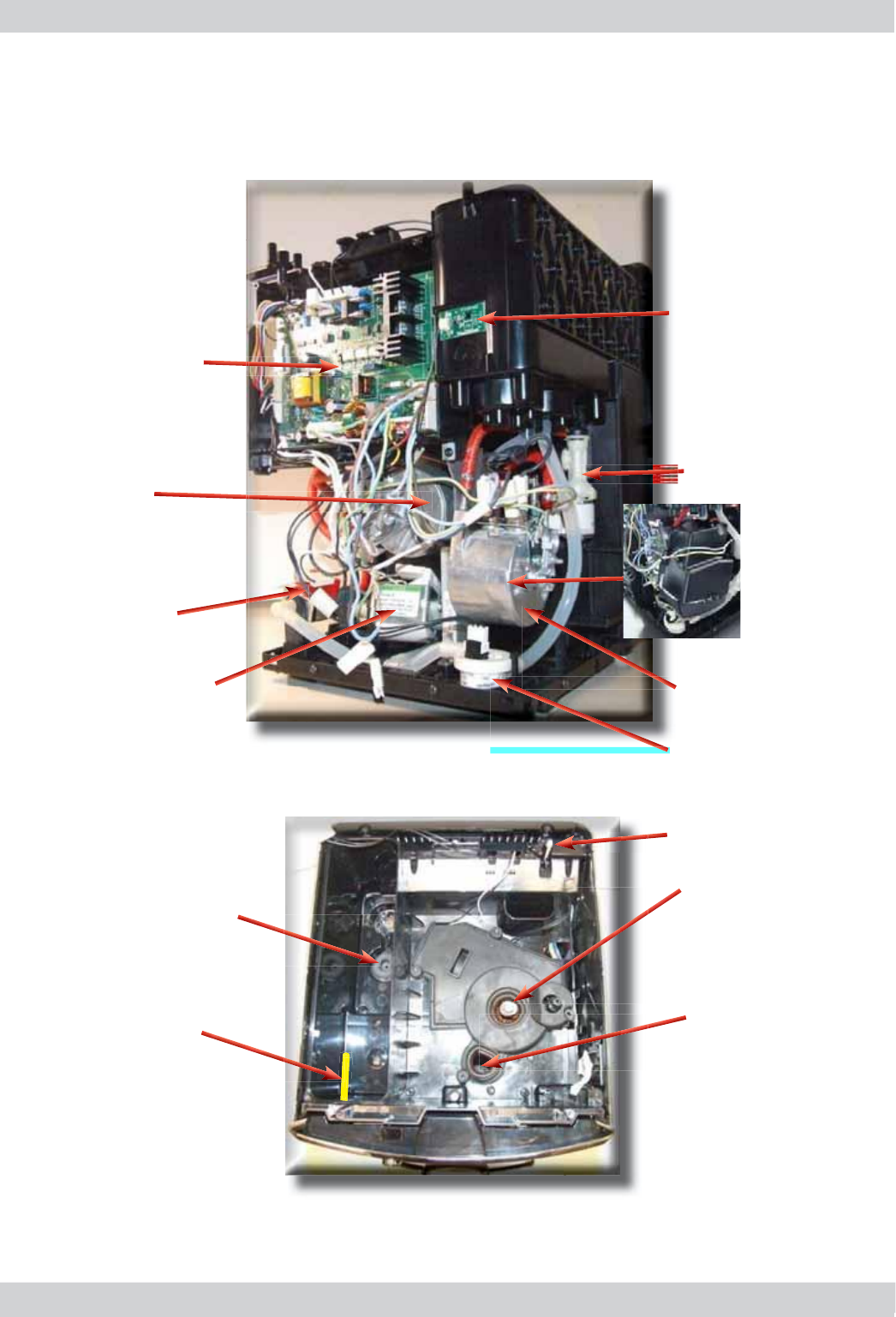
1.6.1 External machine parts
ACCADEMIA 01 INTRODUCTION
GAGGIA Rev. 00 / March 2010 Page / 04
1
.
6
.
2
Interna
l
mac
h
ine
p
art
s
04
Water level
capacitive sensor
Multi-way valve
Coffee boiler
Coffee boiler
cover
Steam boiler
Power Board
Flow meter
Water pump
Steam pump
Coffee grinder
Ground coffee
conveyor
Coffee cover
presence sensor
Water tank connection
Water tank presence/
absence plate

GAGGIA Rev. 00 / March 2010 ACCADEMIA
CHAPTER 2
TECHNICAL SPECIFICATIONS
ACCADEMIA 02 TECHNICAL SPECIFICATIONS
GAGGIA Rev. 00 / March 2010 Page / 03
7HFKQLFDOVSHFL¿FDWLRQV
Power supply and output: 240 V~ 50 Hz 1400 W - 230 V~ 50/60 Hz 1400 W -
120 V~ 60 Hz 1500 W - 100 V~ 50/60 Hz 1300 W
Temperature monitoring: Variable resistor sensors (NTC)
transmits the value to the control board
Safety system: 2 manual reset or one-shot thermostats (175°C)
Coffee heat exchanger output:
Stainless steel
(230/120 V~) 1300 W – (100 V~) 1100 W
to dispense coffee, hot water and steam
Steam heat exchanger output:
Stainless steel As above
Gearmotor: 2 rotation directions; 24VC power supply
Coffee pump Ulka Type EP5/S GW approx. 13-15 bar with reciprocating
piston and 120°C cutout 48 W, 230V, 50 Hz, 120V, 60Hz 100V,
50/60 Hz
Steam pump Ulka MF with reciprocating piston 230V, 50 Hz, 120V, 60Hz 100V
50/60 Hz
Overpressure valve:
(multi-way valve)
Opening at approx. 17-23 bar
:DWHU¿OWHU In tank
Coffee grinder: 'LUHFWFXUUHQWPRWRUZLWKÀDWFHUDPLFJULQGHUEODGHV
Automatic dosage Dose adjustment controlled by the electronic system
Consumption: During the heating phase - approx. 5.6 A
Consumption in Stand-by < 1 W
Dimensions: W x H x D in mm: 290x375x444
Weight: 16 kg
Water tank capacity: 1.7 l.
Coffee container capacity 250 g coffee beans
Dreg drawer capacity 15
Heat exchanger capacity: Approx. 10 cc
:DWHUFLUFXLW¿OOLQJWLPH $SSUR[VHFPD[RQ¿UVW¿OOLQJF\FOH
Heating time: Approx. 45 sec.
Dispensing temperature: Approx. 84°± 4°
Grinding time: Approx. 8-10 sec.
01
ACCADEMIA 02 TECHNICAL SPECIFICATIONS
GAGGIA Rev. 00 / March 2010 Page / 03
2.2. Machine parameters and performance
PRODUCT
QUANTITY
Min
quantity
(Puls.)
Max
quantity
(Puls.)
Max
quantity
(Puls.)
Set
by the user
Set by
the Production/Service
Dept
Expresso 50 130 - 170 *600 Yes No
Expresso
lungo 70 200 - 230 *600 Yes No
Pre-ground Yes
Hot water Continues for 400 pulses
Steam
nozzle Continues until the water is used up (capacitive sensor)
* Depends on the language selected by the user
RINSE Initial rinse Final rinse
When performed When the machine is switched on
and the temperature of the
ERLOHUUHDFKHV&
When the machine is switched
off electronically, manually or
automatically after 60', if at least
one coffee has been dispensed
before being switched off
No. of Pulses 130 100
Stop option Yes, by pressing any key Yes, by pressing any key
Can be disabled by the user Yes No
Can be disabled by
the Production/Service Dept No No
No. of pulses adjustable by
the user No No
No. of pulses adjustable by
the Production/Service Dept No No
Pulse range
(Min - Max) No No
02
Descaling frequency
Hardness Water hardness :LWKRXWDQWLVFDOH¿OWHU :LWKDQWLVFDOH¿OWHU
1Soft (up to 7°dH) 240 litres (480,000 pulses) 480 litres (960,000 pulses)
2Medium (7° - 14°dH) 120 litres (240,000 pulses) 240 litres (480,000 pulses)
3Hard (15° - 21°dH) 60 litres (120,000 pulses) 120 litres (240,000 pulses)
4Very hard
(over 21°dH) 30 litres (60,000 pulses) 60 litres (120,000 pulses)
The default water hardness level is 3. Each litre of water corresponds to approximately 2,000 pulses
ACCADEMIA 02 TECHNICAL SPECIFICATIONS
GAGGIA Rev. 00 / March 2010 Page / 03
WATER TANK Description
:DWHUUHVHUYHSXOVHVZLWKZDWHU¿OWHU 200
:DWHUUHVHUYHSXOVHVZLWKQRZDWHU¿OWHU 200
:DWHUUHVHUYHPRGL¿DEOHE\WKH3URGXFWLRQ6HUYLFH
Dept
No
"Fill tank" alarm Yes
"No tray" alarm No
Water mains No
DREG DRAWER Description and values
Time-out for dreg drawer 5 sec.
Warning to empty dreg drawer Yes, after 12 lots of dregs
Empty dreg drawer block alarm
(double expresso as the last dispensed product)
15 lots of dregs
(16 lots of dregs)
Reset dreg counter
Only if the Warning or the empty dreg drawer
alarm is triggered and the dreg drawer is
removed for at least 5 seconds.
STAND-BY Description and values
Input time (min - max) 15 minutes - 180 minutes
Input time (default) 60 minutes
Input time set by user Yes
Input time set by
the Production/Service Dept
Yes
Boiler temperature during Stand-by Boiler OFF
Cup heater during stand-by Cup heater OFF
Timer and Stand-by Yes **
** The machine switches on at the TimerOn (Timer) value and switches off when the
"Stand-by input time" (Delay - Time) has elapsed
03

GAGGIA Rev. 00 / March 2010 ACCADEMIA
CHAPTER 3
USER INSTRUCTIONS
ACCADEMIA 03 USER INSTRUCTIONS
GAGGIA Rev. 01 / Jan. 2010 Page / 03
3
.1.
C
ustomer and pro
g
rammin
g
menu
1
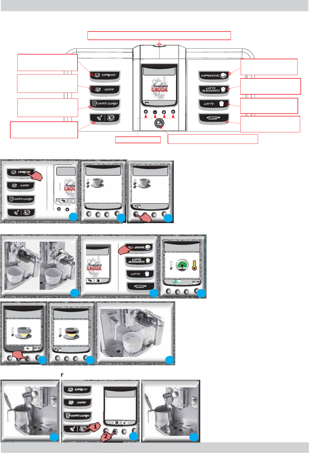
)Press the button pertaining to the desired
p
roduct once for 1
p
roduct and twice for 2
p
ro
d
ucts. To save t
h
e
l
en
g
t
h
,
k
eep t
h
e
b
utton
p
ressed
f
or 3 sec
.
1
)
P
l
ace a container
b
eneat
h
t
h
e
h
ot
w
ater/steam dispensin
g
pipe
2
)
Press button
(
1
)
Press
b
utton
(
2
)
to
d
ispense t
h
e set type
3
)
Remove t
h
e container at t
h
e en
d
.
R
epeat the process to dispense another dose
1
)Place a container and turn the
c
arafe handle clockwis
e
2)
Press t
h
e
b
utton t
h
at corres
p
on
d
s
with the desired bevera
ge
4)
T
h
e mac
h
ine can
d
is
p
ense an a
dd
itiona
l
amount
of milk if the hi
g
hli
g
hted button is presse
d
6)Upon completion, bring the cara
f
e handle bac
k
to t
h
e i
dl
e position, t
h
en t
h
e rinse cyc
l
e
b
egins.
5)The machine dispenses the co
ff
e
e
3)
Mac
h
ine preparation
b
egins
2)Preparation begins by grinding the co
ff
e
e
Ex
p
resso
C
appuccino
/
Latte macc
h
iato
/
Mi
lk
Dispensin
g
h
ot wate
r
3
)The co
ff
ee dispensing phase can be interrupted
a
t any time
b
y pressing
"
STOP
".
01
Button to perform
a cleaning cycle
Button to dispense
a cappuccino
Button to dispense
a latte macchiato
Button to dispense
hot milk
Button to dispense
an expresso
%XWWRQWRVHOHFWÀDYRXU
Button to dispense
hot water and steam
Button to dispense
an expresso lungo
Button to dispense
a coffee
Function keys
Key used to set the machine in stand-by
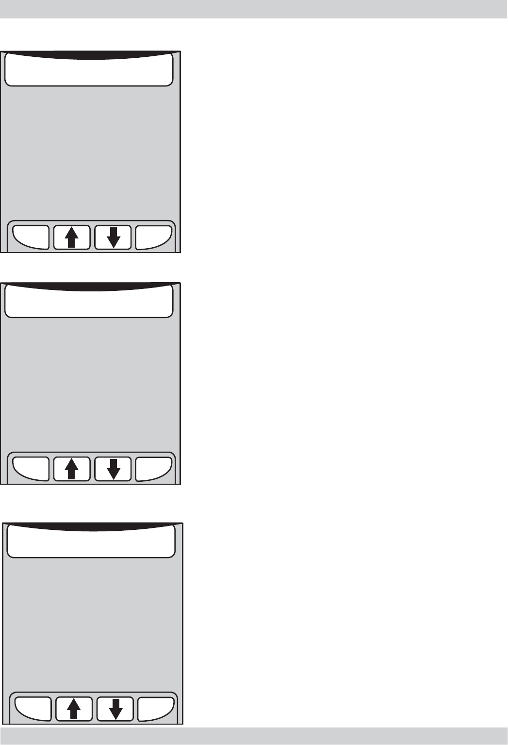
6
CAPPUCCINO
5
ESPRESSO
3
CAPPUCCINO
ECO MODE ATTIVO
3
ESPRESSO
2
15/01/10
10:38
2
15/01/10
10:38
1
1
CAPPUCCINO
4
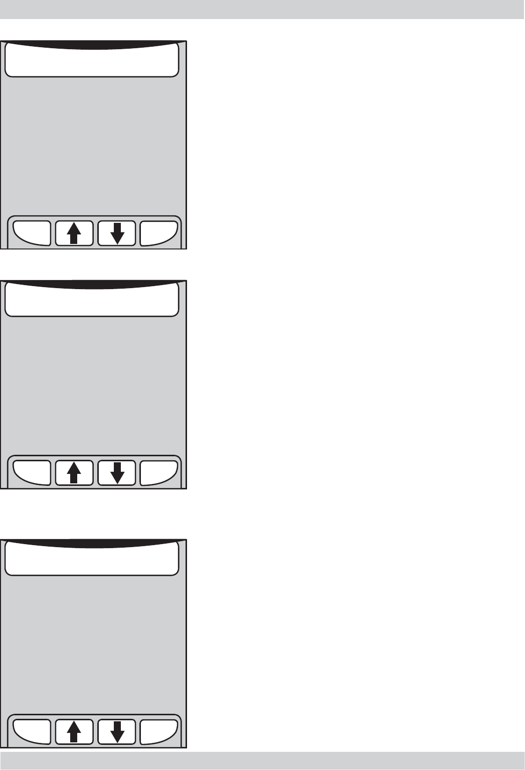
13
3
SELEZIONARE
ACQUA CALDA O VAPORE
15/01/10
10:38
2
SELEZIONARE
ACQUA CALDA O VAPORE
15/01/10
10:38
1
22
ACCADEMIA 03 USER INSTRUCTIONS
GAGGIA Rev. 01 / Jan. 2010 Page / 03
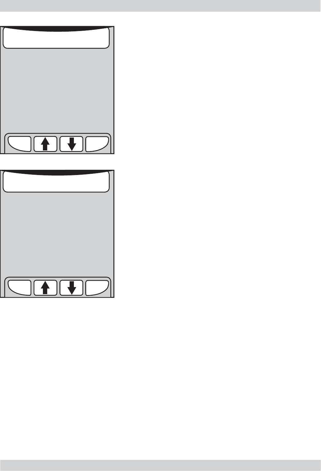
Dispensing stea
m
02
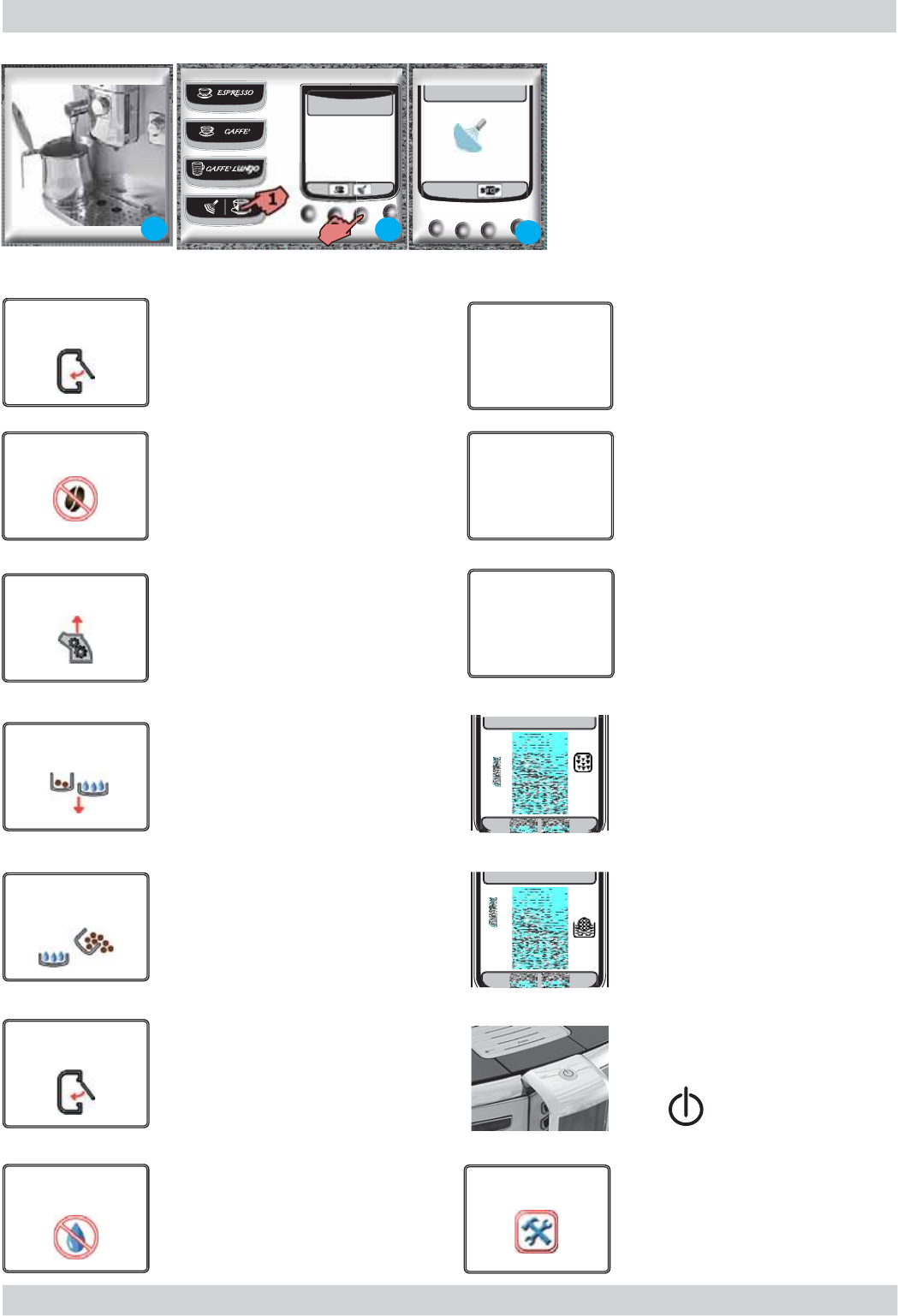
1)
P
l
ace a container
b
eneat
h
t
h
e
h
ot water
/
steam
d
ispensin
g
pip
e
2
)
Press
b
utton
(
1
)
Press button (2)
t
o start
d
ispensin
g
3)
Remove the container at the end.
R
epeat t
h
e process to
d
ispense anot
h
er
d
os
e
1
VAPORE
SELEZIONARE
ACQUA CALDA O VAPORE
15/01/10
10:38
1
223
3
.
2.
Machine si
g
nal
s
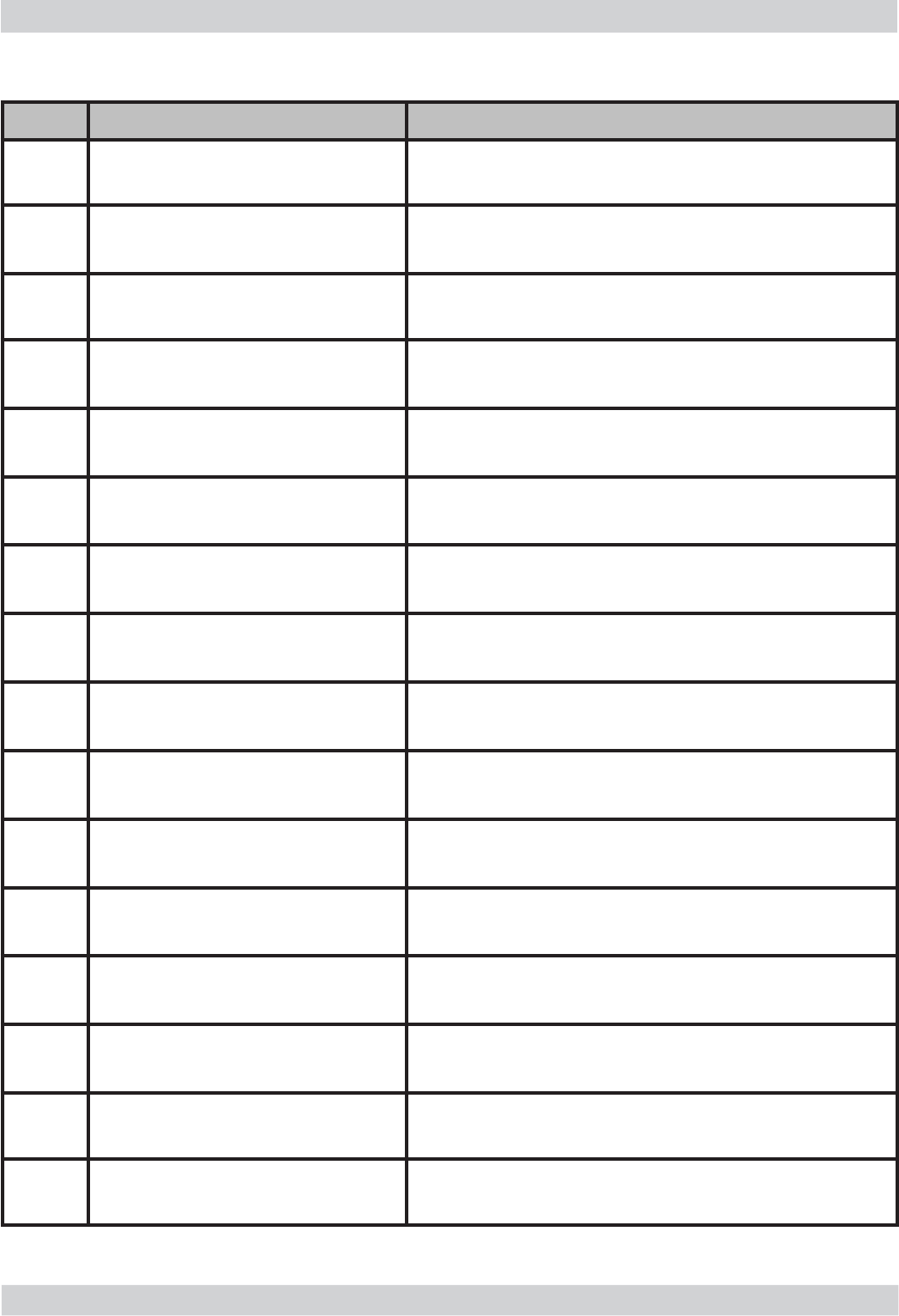
C
lose the coffee bean container lid
f
or any beverage to be dispense
d
A bevera
g
e containin
g
milk has
been selected. Press the "ESC" ke
y
to cance
l
t
h
e se
l
ection
.
The carafe rinse function has been
s
elected. Press the "ESC" ke
y
to
cance
l
t
h
e se
l
ection
.
A
n operation t
h
at requires a
dispensing cycle o
f
the milk
container
h
as
b
een se
l
ecte
d
.
Press t
h
e
"
ESC
"
k
ey to cance
l
t
h
e
s
electi
o
n.
T
h
e mac
h
ine requires a
d
esca
l
in
g
cycle. Damages caused due to
t
h
e
d
esca
l
ing cyc
l
e not
b
eing
imp
l
emente
d
non are not covere
d
by
the warrant
y
.
The machine requires the "Intenza"
ZDW
HU
¿
OW
HU
WR
E
HUH
S
ODFHG ZLWK
D
QHZ
RQH
5H
SO
DF
H
W
KH
¿
OW
H
U
Flashing red LED.
Mac
h
ine in stan
d
-
by
.
Pr
ess
An error
h
as occurre
d
. Ta
k
e note
of the code (E xx). Switch off the
m
a
chine
a
n
d
switch it
ba
ck
o
n
af
ter
30 seconds. If the
p
roblem
p
ersists,
c
o
nt
a
ct t
h
e
a
ssist
a
nce centre
.
Fill the c
off
ee c
o
nt
a
iner with c
off
ee
b
eans
Insert the coffee unit into its
h
ousing
Insert t
h
e
d
re
g
d
rawer an
d
t
h
e
d
rip
t
ra
y
Em
p
t
y
t
h
e
d
ri
p
tra
y
t
h
at is
b
eneat
h
the coffee unit and the dre
g
drawer
.
Onl
y
i
f
the machine re
q
uires it
an
d
it is switc
h
e
d
on.
T
he front door must be closed for
the machine to be functiona
l
5HPRY
H
W
K
H WDQ
N
D
Q
G
¿OO
LW
ZL
WK
f
resh drinkin
g
wate
r
CHIUDERE
SPORTELLO CHICCHI
AGGIUNGERE CAFFE’
INSERIRE GRUPPO
INSERIRE
CONTENITORE FONDI
SVUOTARE VASCA
RACCOGLIGOCCE
E CONTENITORE FONDI
CHIUDERE LO SPORTELLO
FRONTALE
RIEMPIRE IL
SERBATOIO ACQUA
POSIZIONARE L’EROGATORE
DELLA CARAFFA IN POSIZIONE
EROGAZIONE
POSIZIONARE L'EROGATORE
DELLA CARAFFA IN POSIZIONE
RISCIACQUO
POSIZIONARE LA
CARAFFA DEL LATTE
NELL’ALLOGGIAMENTO
10:38
10:38
RIAVVIARE PER RISOLVERE
IL PROBLEMA
E XX
ACCADEMIA 03 USER INSTRUCTIONS
GAGGIA Rev. 01 / Jan. 2010 Page / 03
3.3. Operation, cleaning and maintenance
CLEANING AND TECHNICAL ASSISTANCE
A Empty the dreg drawer If signalled
B Empty the drip tray $VQHFHVVDU\ÀRDW
C Clean the water tank Weekly
D Clean the coffee bean container As necessary
E Clean the casing As necessary
F
Clean the coffee unit (YHU\WLPHWKHFRIIHHEHDQFRQWDLQHULV¿OOHGRU
once a week
Lubricate the coffee unit After 500 dispensing cycles
Clean the unit housing Weekly
H Descaling cycle If signalled
Operating the machine
1 Fill the water tank
2 Fill the coffee bean container
3 Switch on the appliance
4Press to switch on the
machine
5Select the desired language Save
6 Heating 7KHKHDWLQJSKDVHEHJLQVZDLWIRULWWR¿QLVK
7 Rinse Carries out a rinse cycle of the internal circuits
8 Machine ready The machine is ready to dispense beverages
03
Descaling frequency
Hardness Water hardness :LWKRXWDQWLVFDOH¿OWHU :LWKDQWLVFDOH¿OWHU
1Soft (up to 7°dH) 240 litres (480,000 pulses) 480 litres (960,000 pulses)
2Medium (7° - 14°dH) 120 litres (240,000 pulses) 240 litres (480,000 pulses)
3Hard (15° - 21°dH) 60 litres (120,000 pulses) 120 litres (240,000 pulses)
4Very hard
(over 21°dH) 30 litres (60,000 pulses) 60 litres (120,000 pulses)
The default water hardness level is 3. Each litre of water corresponds to approximately 2,000 pulses

GAGGIA Rev. 00 / March 2010 ACCADEMIA
CHAPTER 4
OPERATING
LOGIC
ACCADEMIA 04 OPERATING LOGIC
GAGGIA Rev. 00 / March 2010 Page / 11
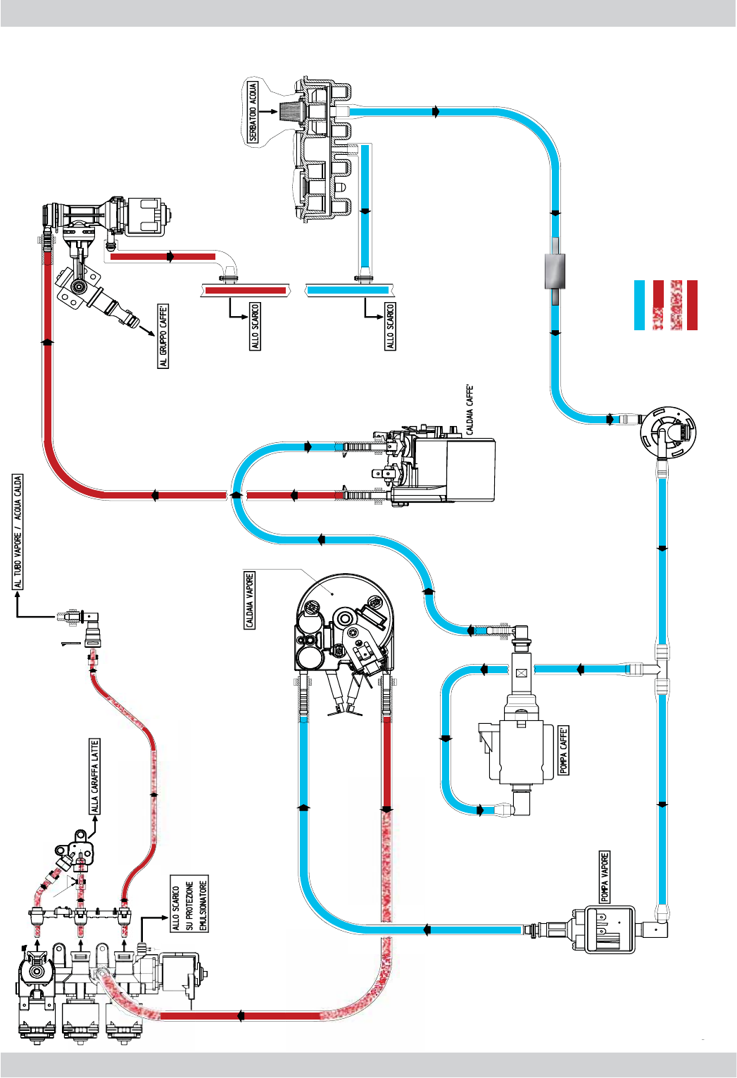
4.
1
. Water c
i
rcu
it
-COLD WATER
- HOT WATER/STEAM
- STEAM
- HOT WATER
01
ACCADEMIA 04 OPERATING LOGIC
GAGGIA Rev. 00 / March 2010 Page / 11
4
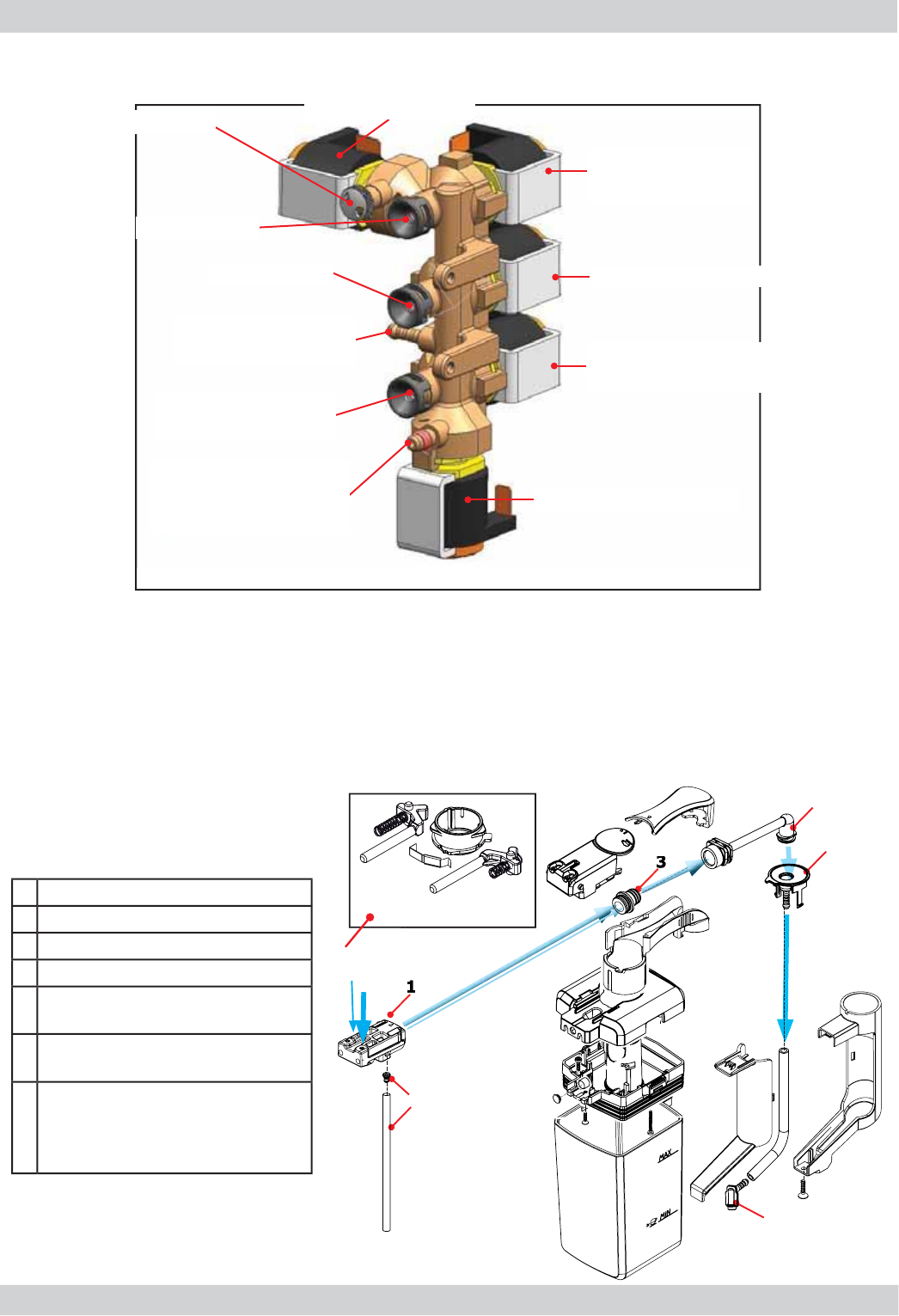
.2.
F
rother valve assembly
02
4.
2
.
1
General carafe assembl
y
6SHFL¿FDWLRQVDQGUHTXLUHPHQWV
Maximum operating pressure 3 bar
Maximum pressure in the water/steam circuit does not exceed 4.5 bar 0/+1
Hot water temperature 90°
Steam temperature 125°
DC3
DC1
DC2
DC4
DC5
Air inlet
Steam outlet
Steam outlet
Hot water/steam
inlet
Hot water/steam
outlet
Drain protection
of the
frother valve
Air solenoid valve
Steam solenoid valve
Clean solenoid valve
(steam)
Hot water/steam
solenoid valve
Drain solenoid valve
1 Cappuccino-maker body
20LONVXFWLRQSLSHDQG¿WWLQJ
3 Venturi pipe
4 Milk dispenser pipe
58SSHU¿WWLQJRIWKHFDUDIHGUDLQSLSH
carafe
6/RZHU¿WWLQJRIWKHFDUDIHGUDLQ
pipe
7 Levers, springs and cam for the
signalling of carafe presence/
absence and the position of the
dispenser
7
4
1
2
3
5
6
ACCADEMIA 04 OPERATING LOGIC
GAGGIA Rev. 00 / March 2010 Page / 11
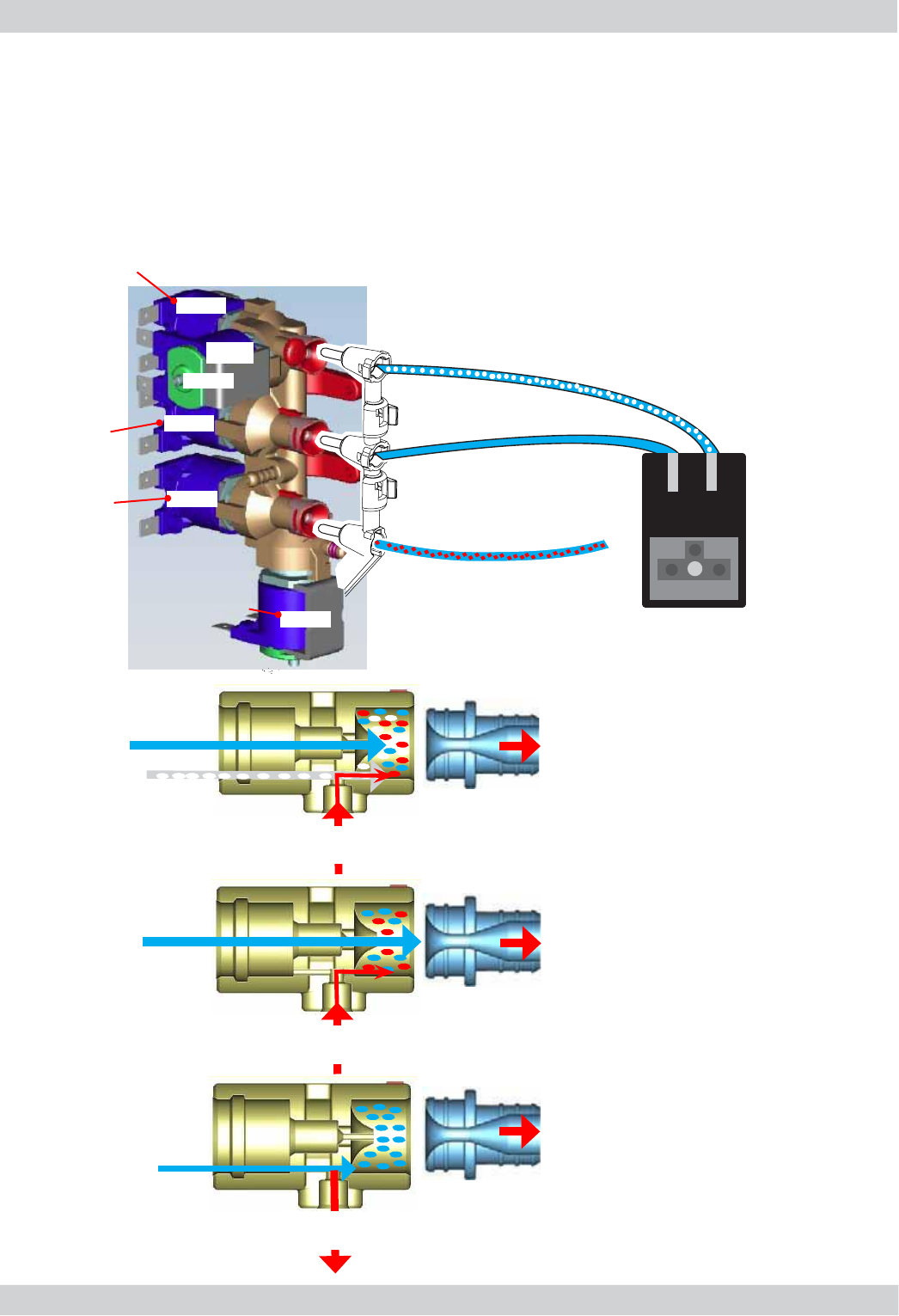
03
STEAM
VENTURI
PIPE
CLEAN / RINSE
MILK IN
CARAFE
AIR
STEAM
VENTURI
PIPE
FROTHED HOT MILK
(CAPPUCCINO)
MILK FROM
CARAFE
STEAM
VENTURI
PIPE
HOT MILK
MILK FROM
CARAFE
Functional mode for the production of milk products and cleaning the circuit
When the solenoid valves open and let air or hot water/steam through, the following situations
occur:
DC3+DC2 STEAM + AIR = Frothing and heating of frothed milk
DC2 STEAM FROM CENTRAL HOLE = Heating of non-frothed milk
DC4 STEAM FROM LOWER HOLE = Cleaning of milk circuits
AIR or STEAM
STEAM
HOT WATER - STEAM
to the steam pipe
DC3
DC4
DC2
DC5
DC1
SAFETY VALVE
Clean
(steam)
Air
Milk products
(steam)
hot water
steam
CARAFE ATTACHMENT
DC1 = safety valve
DC2 = steam valve
DC3 = air valve
DC4 = clean valve (steam)
DC5 = hot water/steam valve
ACCADEMIA 04 OPERATING LOGIC
GAGGIA Rev. 00 / March 2010 Page / 11
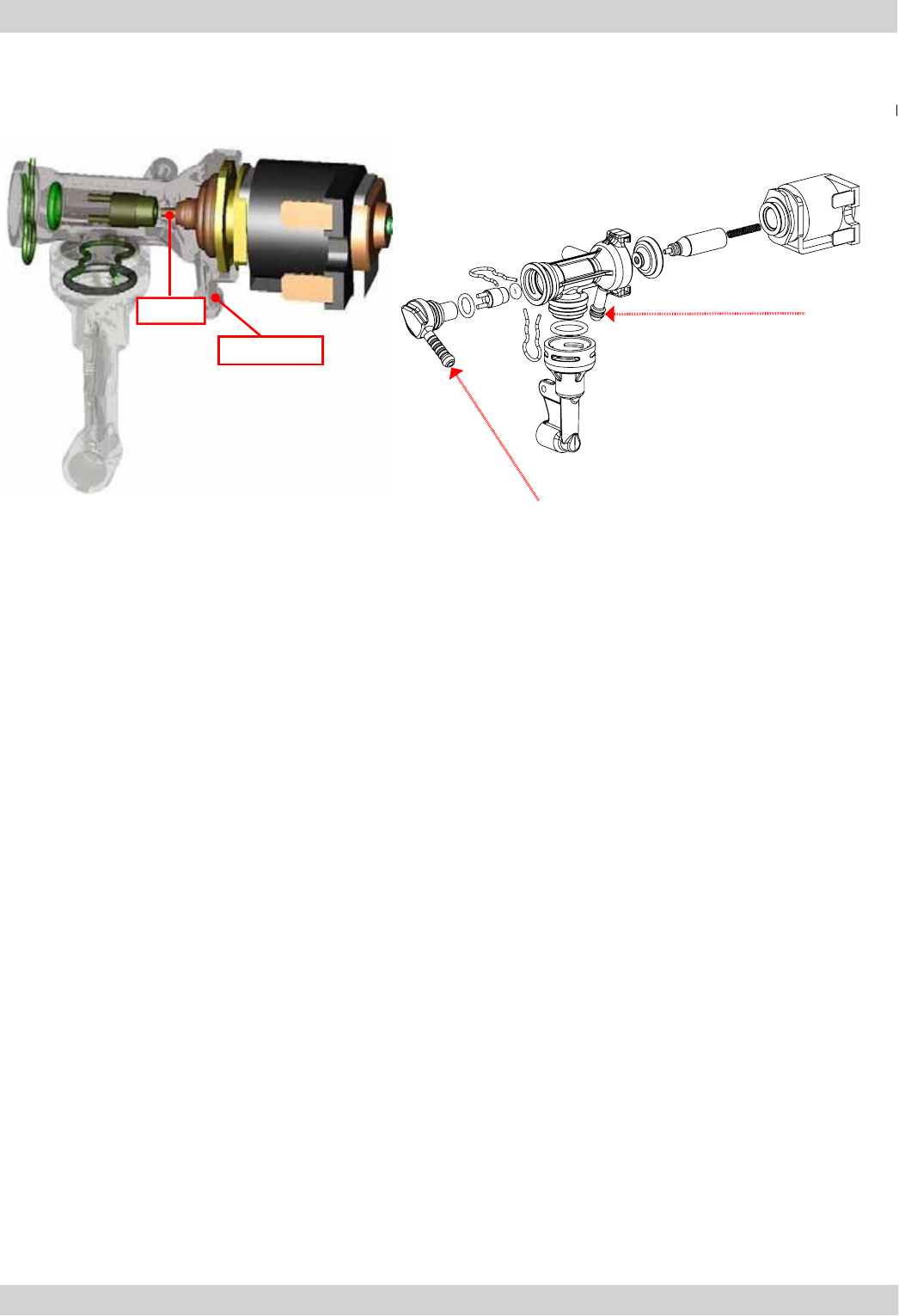
4.3. Multi-way valve
Water inlet from
boiler
Drain to the drip tray
Functions:
Safety valve: opens towards the drain if the pressure exceeds 16-19 bar
Filling the circuitWKHVROHQRLGYDOYHRSHQVGUDLQSRVLWLRQWKHSXPSLVFRQWUROOHGDQGDXWRPDWLFDOO\UH¿OOVWKH
circuit by expelling the air in the pipe
Draining the unitEHIRUHWKHXQLWGHVFHQGVLWRSHQVEULHÀ\UHOHDVLQJWKHSUHVVXUHFUHDWHGWRSUHYHQWWKHXQLWIURP
spraying and making the pad drier
Coffee productZKHQDFRIIHHEHYHUDJHLVVHOHFWHGWKHSXPSLVFKDUJHGEULHÀ\GXULQJWKHJULQGLQJSURFHVVDQGWKH
valve assumes the drain position for hot water to pass through the pipes.
04
Needle
Drain
ACCADEMIA 04 OPERATING LOGIC
GAGGIA Rev. 00 / March 2010 Page / 11
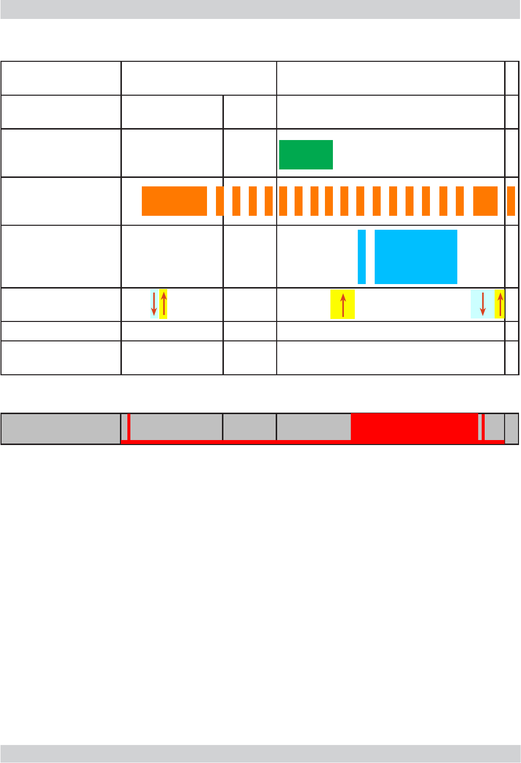
Notes: * Only with Pre-brewing
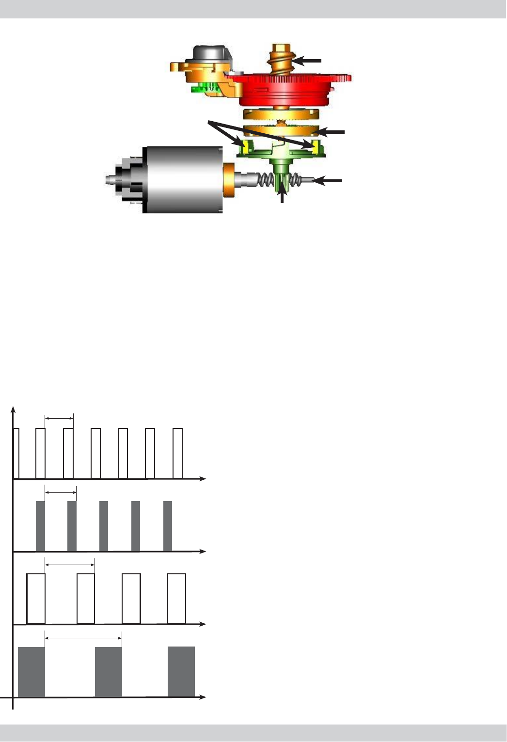
4.4. Coffee cycle
Switching on
When the machine is switched on, the gearmotor repositions itself as follows:
- It stresses microswitch 1 (see the following chapter)
- The gearmotor changes the rotation direction and moves upwards again by approx. 1-2 mm
- The boiler begins to heat the water for approx. 45 sec. at full power in order to
reach the optimal temperature. The temperature will then remain constant.
Coffee cycle
The coffee grinder starts the grinding process (controlled by pulses generated by a sensor)1.
The gearmotor (coffee unit) moves to the dispensing position2.
Preliminary dispensing phase (short pump activity, short pause)3.
The product is dispensed (the pump operation time depends on the amount of product 4.
dispensed)
The gearmotor moves to the idle position (the dregs are expelled automatically)5.
Main Switch
ON
START STOP
Time
Coffee grinder
Heating
Pump
Gearmotor
Brewing unit
Status Heating Ready Coffee cycle
Pulses
(Dosage)
Pump action
ÀRZPHWHUSXOVHV
depending on
the quantity of the
product set
approx.45 sec.
*
05
Single microswitch gearmotor
OFF ON
MicroSwitch
Status
ACCADEMIA 04 OPERATING LOGIC
GAGGIA Rev. 00 / March 2010 Page / 11
An NTC is used as a temperature sensor and in the event of overheating, it reduces the
resistors consumption.
The electronic system detects the actual boiler temperature from the drop in voltage and
adjusts it accordingly.
Resistor values and corresponding temperatures: see table
4.6. Temperature sensor (adjustment)
Temp. (° C) 5QRPN Ʃ5
20 61.465 8.6
50 17.599 5.9
75 7.214 4.1
80 6.121 3.7
85 5.213 3.4
90 4.459 3.1
100 3.3 2.5
125 1.653 3.9
150 0.893 5.1
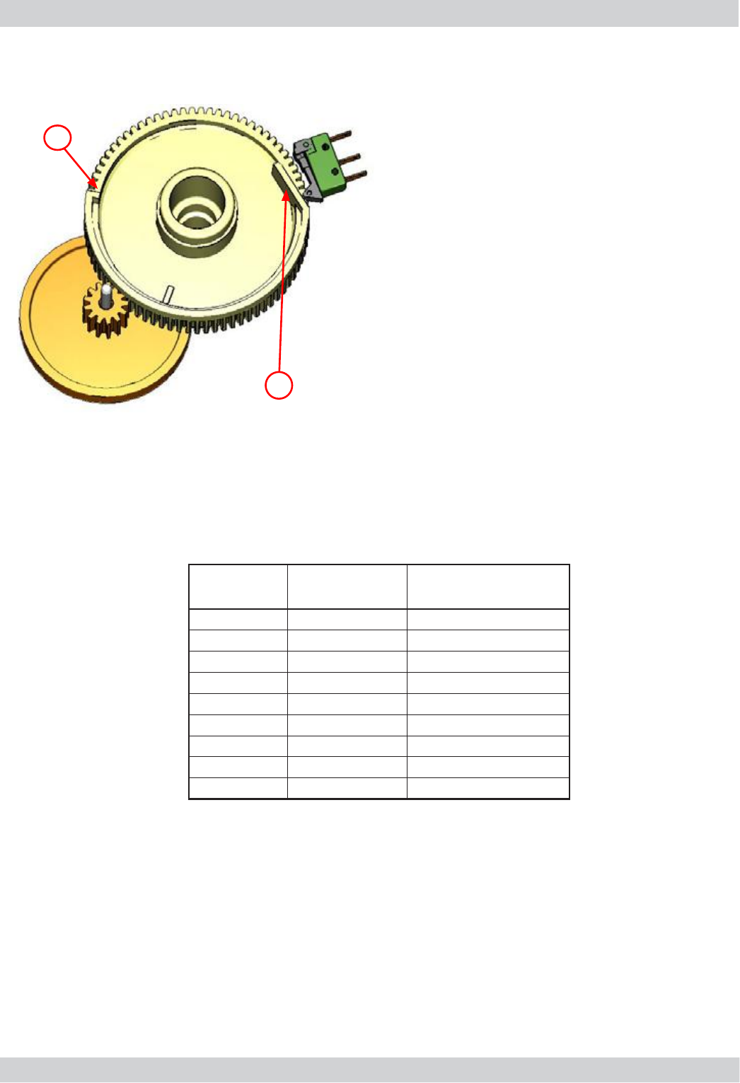
4.5. Single microswitch
The gearmotor is activated by a direct current
motor that acts on the smaller double toothed
wheel via a worm screw. The unit is mounted
on the axle of the large toothed wheel and
when a coffee is requested, it moves from the
idle position to the dispensing position to then
return to the idle position.
- Idle position: 1
- Dispensing position: 2
2
1
06
ACCADEMIA 04 OPERATING LOGIC
GAGGIA Rev. 00 / March 2010 Page / 11
4.7. Coffee grinder
2
3
4
5
6
1
4.8. Detection of coffee bean absence, dose adjustment,
blocked coffee grinder
t1
V
t2
t3
t4
t
Without beans n=100%
With beans n=100%
Without beans n=50%
With beans n=50%
The coffee grinder is activated by a direct current motor (1) via helicoidal wheel transmission and
a worm screw (2).
The worm screw (2) activates a plastic toothed wheel (3), which turns the lower grinder blade (4)
and the increment pin (5).
There are two magnets (6) in the toothed wheel and with every rotation they transmit two pulses
to a Hall sensor, which in turn transmits them to the electronic system.
No coffee
W
hen no coffee beans are present, this is detected by the Hall
sensor due to variations in the pulse frequency (with or without
coffee).
If there are no coffee beans (operation while empty), the number
of rotations and therefore the number of pulses, will be greater
t1 = no coffee signal
If there are coffee beans, the number of rotations will be
lower due to the force created during the grinding process
t2 = no signal
t3 and t4 = this reading is taken
at the end of each grinding process
Dose quantity adjustment
The dose quantity is adjusted in accordance with the pulses
detected
(number of rotations proportional to the weak, medium and
VWURQJÀDYRXUVHOHFWLRQ
Blocked grinder blades
If the coffee grinder is blocked for any reason, pulses will no
longer be transmitted to the electronic system and the grinder
stops
07
ACCADEMIA 04 OPERATING LOGIC
GAGGIA Rev. 00 / March 2010 Page / 11
4.9 Auto-learning dose (SAS)
08
The aim of this function is to automatically adjust the average dose of ground coffee (AUTO-
LEARNING); this occurs by means of an algorithm based on three pieces of information detected
by the machine board:
1. Number of coffee grinder pulses during the grinding cycle
2. Max average value of the power consumed by the gearmotor during the coffee brewing cycle
3. Flavour selected by the user
The algorithm compares the maximum average value of the power consumed by the gearmotor
ZLWKWKHYDOXHVKRZQLQWKHWDEOHGHSHQGLQJRQWKHVHOHFWHGÀDYRXULQRUGHUWRFDOFXODWHWKHQHZ
grinding pulse value for the next coffee product.
If the consumption value is less than the minimum current value, the grinding pulses will be in-
creased by 2.
If the consumption value is greater than the maximum current value, the grinding pulses will be
decreased by 4.
If the consumption value falls within the "excessive stress" range, the product is dispensed and
the grinding pulses will be decreased by 10.
If the consumption value falls within the "expel" range, the pad will be expelled and the grinding
pulses decreased by 10.
,IWKHSUHJURXQGÀDYRXULVVHOHFWHGE\WKHXVHUQRPRGL¿FDWLRQLVPDGH
This guarantees that regardless of the coffee type used, the grinding adjustment
and any wear on the grinder blades always remains constant.
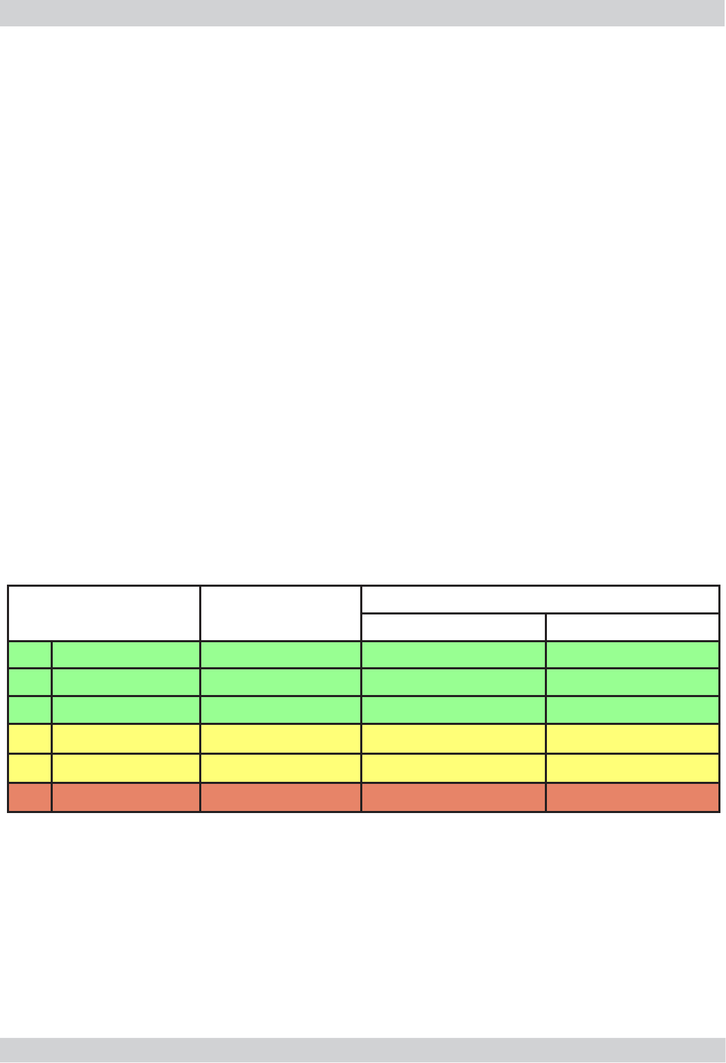
Important:
)RUSHUIHFWRSHUDWLRQWKHDGMXVWPHQWLVFDUULHGRXWLQWKHDUHDRIWKH¿HOGVKLJKOLJKWHGLQ
green (A, B and C). When the type or brand of coffee is changed, there may be variations
in the size of the beans and their stickiness or roasting level. This leads to variations in
SRZHUFRQVXPSWLRQP$UHVXOWLQJLQH[FHVVLYHRULQVXI¿FLHQWGRVHVXQWLOWKHDGMXVWPHQW
compensates this change).
Caution: In case of an excessive dose, ground coffee can fall into the dreg drawer.
This is not a fault, but can occur when the machine is switched on or following a
service.
Setting / Status Power consumption
in mA
The pulse is corrected in the next grinding process
Exceeded in excess Exceeded in default
A0LOGÀDYRXU 200 - 300 mA - 4 +2
B Medium Flavour 301 - 450 mA - 4 +2
C Strong Flavour 451 - 600 mA - 4 +2
D Stress 601 - 800 mA - 4
E Excessive stress 801 - 1,000 mA - 10
F Pad expulsion > 1000 mA - 10
ACCADEMIA 04 OPERATING LOGIC
GAGGIA Rev. 00 / March 2010 Page / 11
09
SBS Principle - Saeco Brewing System
$GMXVWLQJWKHÀRZVSHHGZKLFKLQÀXHQFHVWKH
contact time between the coffee and water,
alters the extraction and therefore the taste
intensity and strength of the coffee.
6ORZHUÀRZ6WURQJHUH[WUDFWLRQ
)DVWHUÀRZ/LJKWHUH[WUDFWLRQ
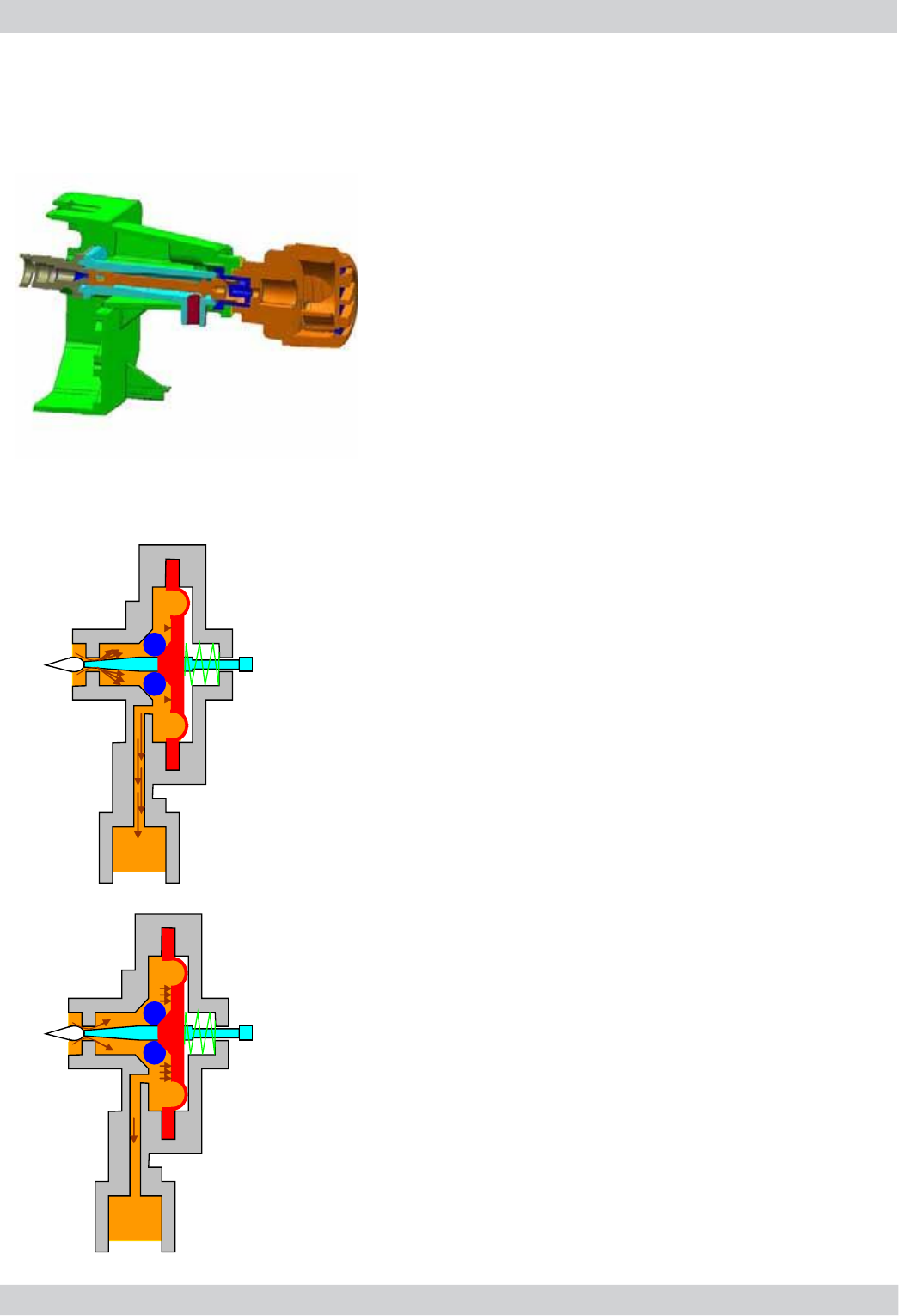
SBS dispensing valve
Turning the SBS adjustment knob will trigger
the brewing process in the coffee unit, where
WKHÀRZVSHHGLVDGMXVWHGYLDDFUHDPYDOYH
Cream valve adjustment
*UHDWHUÀRZOLJKWH[WUDFWLRQ
,IWKH6%6YDOYHLVRSHQWKHFRIIHHÀRZV
easily because the pressure is lower and
the membrane remains almost in its base
position with the help of the spring.
The adjustment needle does not close the
RSHQLQJDQGWKHÀRZGRHVQRWGHFUHDVH
Cream valve adjustment
6ORZÀRZVWURQJH[WUDFWLRQ
The coffee is dispensed slowly with the SBS
valve closed due to the pressure created,
which acts on the membrane and presses it
to the side against the spring force.
Lastly, the valve needle closes the opening,
WKHUHE\UHGXFLQJWKHÀRZ
4.10. SBS
ACCADEMIA 04 OPERATING LOGIC
GAGGIA Rev. 00 / March 2010 Page / 11
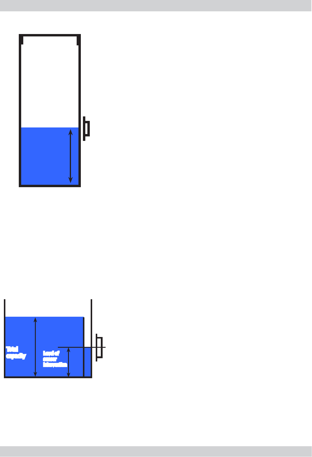
Empty residual water tank signal
Function:
The residual water level is monitored by a capacitive
sensor. The sensor is located approximately half way up
the upper edge of the residual drip tray. To make the best
of the tray capacity, the sensor is positioned near a dam
GHYLFH,QWKLVZD\WKHUHVLGXDOZDWHUWUD\¿OOVXSWRWKH
XSSHUHGJHDQGRYHUÀRZVLQVLGHDQGZKHQLWUHDFKHVWKH
sensor, it triggers the "empty residual water tank" signal.
Residual water tank
Level of
sensor
intervention
Total
capacity
Sensor
4.12. Drip tray water level detection
4.11 Water level detection in the tank
Water absence signal (water reserve)
Function:
The water level is monitored by a capacitive sensor, located one
third up the water tank wall.
If the electronic system detects that the water is below the relative
level by means of the sensor, a water reserve of 200 pulses of the
ÀRZPHWHUUHPDLQVDYDLODEOHIRUWKHGLVSHQVLQJSURFHVV
The product dispensing process is then completed.
If a dispensing process ends after the sensor has intervened (in the
reserve), the "water absence" signal continues to be displayed as
from the next dispensing process
200 puls.
Sensor
Water tank
10
ACCADEMIA 04 OPERATING LOGIC
GAGGIA Rev. 00 / March 2010 Page / 11
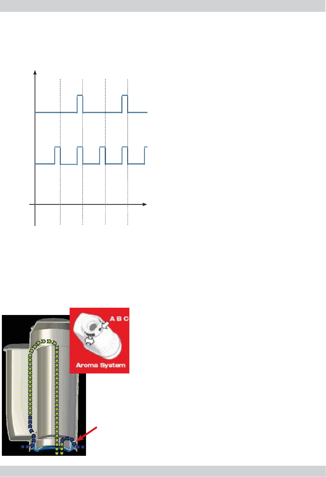
'HVFDOLQ
J
VL
J
QDOZLWKDQWLVFDOH
¿
OWHU
(
only in appliances equipped with a display
)
The water hardness is set on the basis o
f
the
re
g
ional water hardness analysis
(
1, 2, 3, 4).
Filter disabled
:
I
f
the
f
unction is
d
isabled, the electronic system
F
RXQ
WV
W
K
H
À
R
Z
P
H
W
HU
S
XOVHV
U
HFRUGLQ
J
one pulse
f
or every revolution.
Filter enabled
:
I
f
the
f
unction is
e
nabled
,
the electronic system
F
RXQ
WV
W
K
H
À
R
Z
P
H
W
HU
S
XOVHV
U
HFRUGLQ
J
one pulse
f
or every two revolutions
.
&KDQ
J
HDQWLVFDOH
¿
OWHUVL
J
QDO
7KH
H
OHFWURQLF
V
\V
W
HP
X
V
HV
WKH
À
RZ PH
W
HU
S
XOVHV
WR
N
HHS
W
UDFN
RI
W
KH
D
PRXQ
W
RI
Z
D
W
HU
W
KDW
À
RZV
D
QG
RQ
F
H
W
K
H
G
H
¿
QH
G
OLWUHV
D
U
H
H
[FHHGHG
EDVH
G
RQ
W
KH
Z
D
W
HU
K
DUGQHVV
V
HWWLQ
J
W
KH 5HSODFH
¿
OWHU
si
g
nal is tri
gg
ered
.
$
QWLVFDOH
¿
OWH
U
F
unct
io
n
:
Reduced limescale deposits that take lon
g
er to
f
orm
.
I
mprove
d
water qua
l
ity
.
Better taste
d
ue to i
d
ea
l
water
h
ar
d
ness
.
'
HVFDOLQ
J
GXUDWLRQH
I¿
FLHQF\
- 10°
dH
6
0
l
itres
2 mont
h
s
T
o obtain a linear characteristic o
f
its e
ff
ectiveness
,
throu
g
hout the duration o
f
the descalin
g
process, the
w
ater is split accordin
g
to the de
g
ree o
f
hardness in a
t
h
ree-p
h
ase
b
y-pass
(
A, B an
d
C
)
.
See sma
ll
picture.
B
ypass
$QWLVFDOH
¿
OWHU
4.1
3.
Desca
l
ing request
3
60
°
1
re
v
Number of pulses
u
f
F
i
l
te
r
enabled
F
i
l
ter
disabled
Flow meter
p
ulses
11

GAGGIA Rev. 00 / March 2010 ACCADEMIA
CHAPTER 5
TROUBLESHOOTING
ACCADEMIA 05 TROUBLESHOOTING
GAGGIA Rev. 00 / March 2010 Page / 12
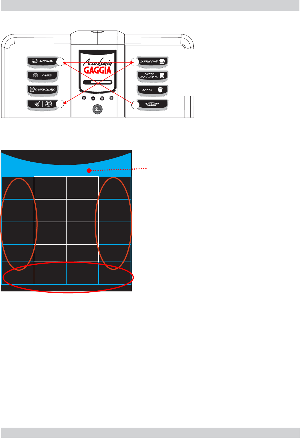
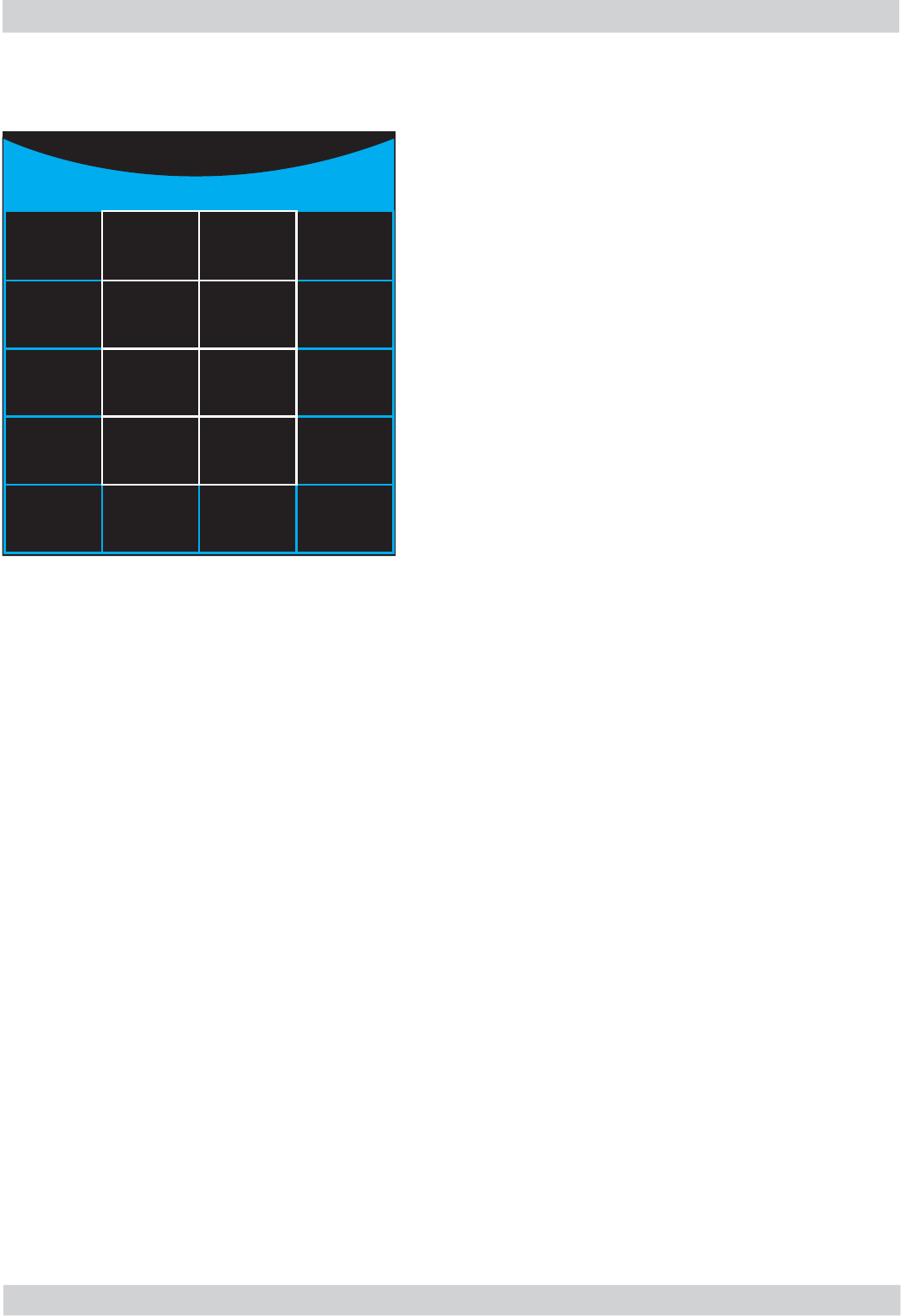
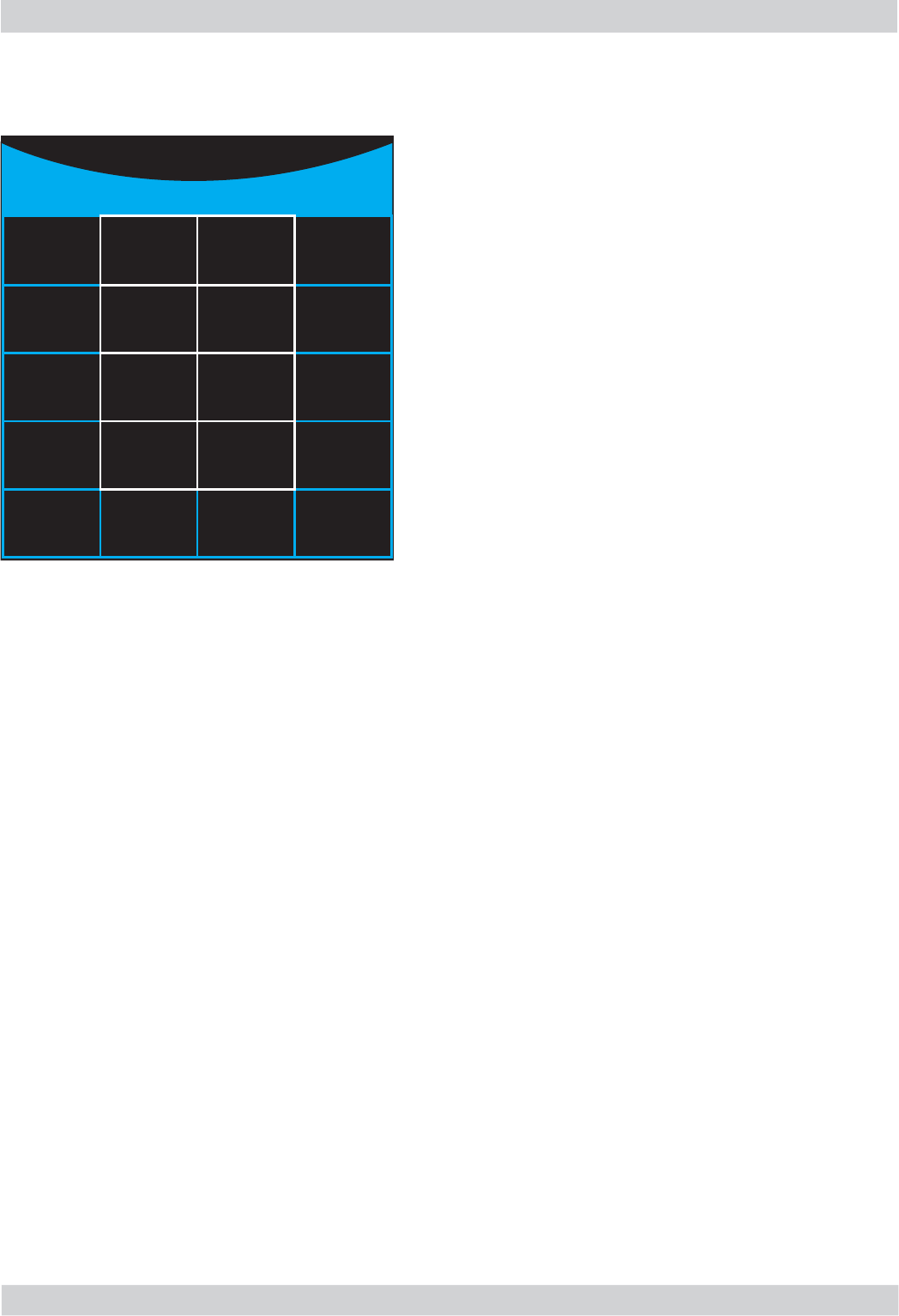
5.1. Test mode
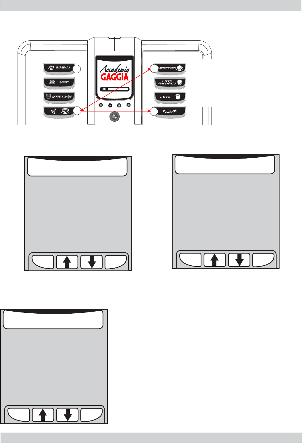
Entering Test Mode presents a screen divided into sections as shown in the diagram below
01
1
23
4
At the top of every page of the Test Mode there is the
reference number and the title
Sections 1 to 8
These can be enabled via the product buttons, as shown in
the picture.
Every page of the Test Mode contains a description of the
function implemented when the relative product button is
pressed. When the function associated with the sector is
enabled, the sector is displayed on a white background; if
disabled, the background is black.
THE TEST MODE is split on to 5 pages
- page 1 Software Version
- page 2 Brewing Unit
- page 3 Hydraulic Circuit
- page 4 Grinder Unit
- page 5 Boiler and Steam Out
Sections 9 to 12
Indicate the function implemented when the 4 navigation buttons beneath the display are pressed.
- MENU 1 button: ESC function to exit the Test Mode
- MENU 2 button: previous page function
- MENU 3 button: next page function
- MENU 4 button: not enabled
Sections 13 to 20
Indicate the status of the system variables (sensor status or values of variables used in the software)
1)EXPRESSO
button 13 14
5)
CAPPUCCINO
button
2)COFFEE
button 1 5 1 6
6) LATTE
MACCHIATO
button
3)EXPRESSO
LUNGO button 17 18 7) MILK
button
4)HOT WATER
STEAM button 19 20 8) CLEAN
button
9) MENU 1
button
10) MENU 2
button
11) MENU 3
button
12) MENU 4
button
1 Page title
To enter Test Mode:
- Switch on the machine
- Wait for the initial progress bar
- Press the four function keys in the
sequence indicated (1, 2, 3, 4)
ACCADEMIA 05 TROUBLESHOOTING
GAGGIA Rev. 00 / March 2010 Page / 12
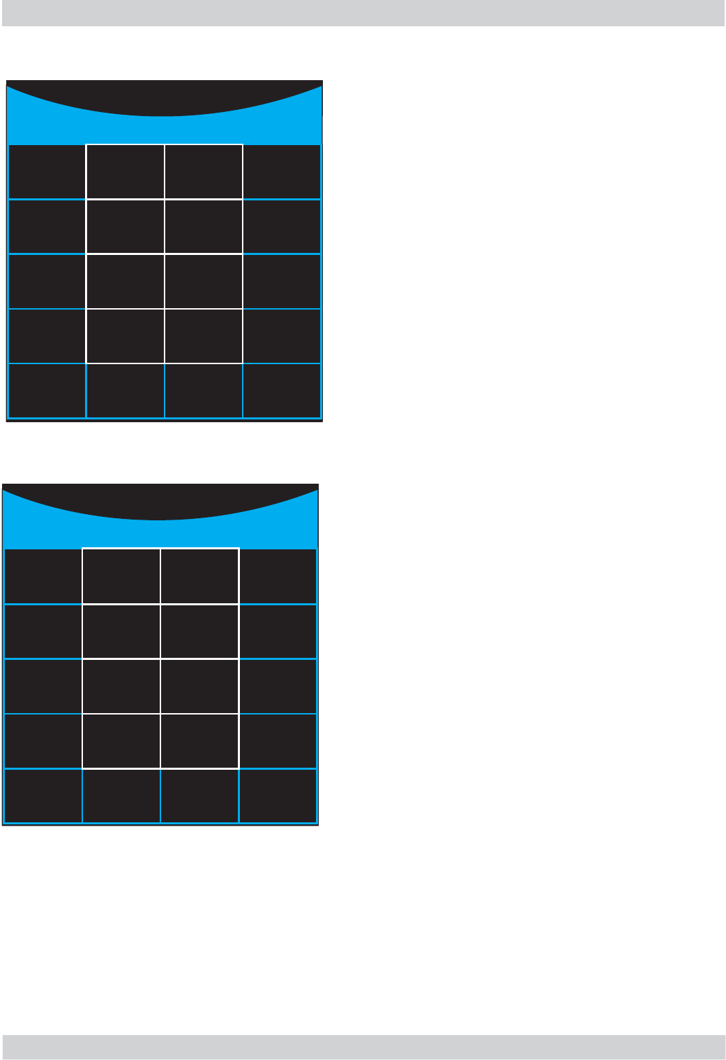
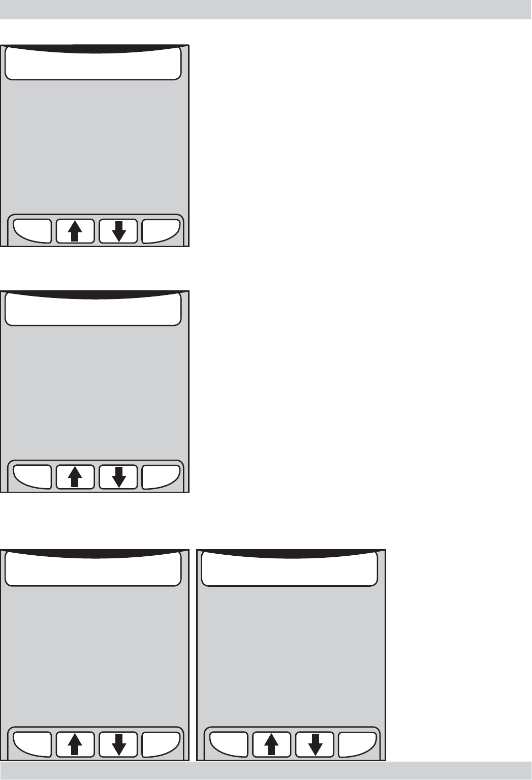
Software Version
This page provides information regarding the status of the software loaded on to the machine
Brewing Unit
This page lets the user control the inner area of the front door
02
SWISS SW CPU:
xx.yy.zz **
DFPART
64
SW KEYB:
xx.yy.zz * OLD
HW
ERPART
8***
SWITCH
OFF ***
ESC PAGE
5
PAGE
2
1 Software Version
*
BU CURRENT:
(mA) 0
DREG
COUNTER
13
*
BU
GO WORD
BU
HOME
WORK
*
MAX
DREG
+
BU
STOP
BU
PRESENT
BU_DREG
DRAWER
MAX
DREG
-
BU
GO HOME
BU
DOOR **
ESC PAGE
1
PAGE
3
2 Brewing Unit
SW CPU: indicates the software version of the CPU
SW KEYB: indicates the software version of the keyboards
SWISS: indicates whether the "SWISS" function is enabled or
not. It is used to control the default value of the ECO-MODE
function
SWITCH OFF: indicates whether the machine goes into Stand-
by once it is powered via the electromechanical switch (I/O). If
so, "SWITCH OFF" is highlighted
OLD HW: manages the type of Hardware (control boards). It
must be disabled for this type of machine (black background)
DFPART and ERPART: provide only information regarding save
settings. Their respective values must be 64 and 8.
CONTROLS
BU GO WORK: if pressed, the unit switches to the
WORK position
BU GO STOP: if pressed, the unit is stopped instantly if it is in
motion
BU GO HOME: if pressed, the unit switches to the
HOME position
MAX DREG+: increases the coffee dreg counter
INDICATORS
BU CURRENT: indicates the current consumed by the unit when in motion MAX 300mA.
BU HOME WORK: is enabled (white) when the unit reaches a position between WORK and HOME
DREG COUNTER: indicates the coffee dreg counter value
BU PRESENT: if enabled, it indicates that the unit is connected
BU DREG DRAWER: if enabled, it indicates that the coffee dreg container is connected
BU DOOR: if enabled, it indicates that the front door is closed
ACCADEMIA 05 TROUBLESHOOTING
GAGGIA Rev. 00 / March 2010 Page / 12
03
INDICATORS
FLOW_METERLQGLFDWHVWKHZDWHUÀRZUDWHLQWKHÀRZPHWHUH[SUHVVHGLQSXOVHVSHUVHFRQG
When coffee pump 1 is switched on (and EV_AC_COFFEE is on), the value must not be less than 10 p/s.
When the hot water/steam pump 2 is switched on (and EV_DC_DISCHARGE is on), the value must not be less than 5
p/s.
POWER FREQ.: indicates the frequency of the power supply voltage
DRIP DRAY: indicates the status of the tray level sensor. If enabled, it indicates that the level has been reached
WATER TANK: indicates the status of the water tank level sensor. If enabled, it indicates that the level has been
reached
CARAFFE CLEAN: if enabled, it indicates that the milk carafe is in the CLEAN position
CARAFFE MILK: if enabled, it indicates that the milk carafe is in the MILK dispensing position
CARAFFE PRESENT: if enabled, it indicates that the milk carafe is connected
PUMP 1
COFFEE
FLOW
METER
(p/s) 0
POWER
FREQ.
(Hz) 50
EV DC2
STEAM
PUMP 2
WATER &
STEAM
DRIP
DRAY
WATER
TANK
EV DC3
AIR
EV AC
COFFEE
CARAFFE
CLEAN
CARAFFE
MILK
EV DC4
CLEAN
EV DC1
DISCHAR.
CARAFFE
PRESENT
DRIP
DRAY
EV DC5
HOTWATER
ESC PAGE
2
PAGE
4
3 Hydraulic Circuit
Hydraulic Circuit
This page pertains to the water circuit management
CONTROLS
PUMP1 COFFEE: if pressed, the coffee boiler pump is activated
and if pressed again, it is disabled
PUMP2 WATER&STEAM: if pressed, the steam/hot water boiler
pump is activated and if pressed again, it is disabled
EV_AC COFFEE: if pressed, the 230 V solenoid valve is activated
EV_DC1 DISCHARGE: activates the 24 V solenoid valve for the
draining process
EV_DC2 STEAM: activates the 24 V solenoid valve to dispense
the steam
EV_DC3 AIR: activates the 24 V solenoid valve to froth the milk
EV_DC4 CLEAN: activates the 24 V solenoid valve to clean the
milk circuit
EV_DC5 HOTWATER: activates the 24 V solenoid valve to
dispense hot water
ACCADEMIA 05 TROUBLESHOOTING
GAGGIA Rev. 00 / March 2010 Page / 12
CONTROLS
GRINDER GO: if pressed, the coffee grinder is activated. To
stop it, press the button again. If it is not stopped, it will grind
for 200 pulses and the corresponding countdown appears in the
window.
CUP HEATER: if pressed, the cup heater is activated. It is
switched off by pressing the button again.
BEAN LESS TEST: if pressed, the coffee presence/absence test
is performed. When the coffee grinder is activated, a number
of pulses equal to the number set for the "MEDIUM DOSE" is
performed. At the end of the grinding cycle, the values of the
"BEAN FACTOR" and "BEAN LESS" sections are updated and if
the absence of coffee is detected, the "BEAN LESS ALARM" sec-
tion is enabled
MEDIUM DOSE +: if pressed, the average dose value
displayed in "MEDIUM DOSE" is increased
MEDIUM DOSE -: if pressed, the average dose value displayed
in "MEDIUM DOSE" is decreased.
04
*
GRINDER
PULSE
0
MEDIUM
DOSE
100
*
GRINDER
GO
BEAN
FACTOR
20
BEAN
LESS
28
MEDIUM
DOSE
+
CUP
HEATER
BEAN
DOOR
BEAN
LESS
ALARM
MEDIUM
DOSE
-
BEAN
LESS
TEST
NET
STABLE *
ESC PAGE
3
PAGE
5
4 Grinder Unit
Grinder Unit
This page pertains to the coffee grinder and cup heater management.
INDICATORS
GRINDER_PULSE: indicates the real-time grinding pulse countdown during the grinding process
MEDIUM_DOSE: indicates the pulses pertaining to the average dose
BEEN FACTOR: indicates the result of the last grinding cycle, calculated using the automatic dose adjustment
algorithm. The default value is 17 and is dynamically updated with the grinding cycles.
BEEN LESS: indicates the threshold set by the dynamic threshold algorithm for the absence of coffee to be detected
BEEN DOOR: indicates the status of the bean container door sensor (if enabled, it indicates that the door is closed)
BEEN LESS ALARM: indicates the result of the coffee presence/absence test (if enabled, it indicates the absence of
coffee)
NET STABLE: indicates whether the mains maintained a stable frequency during the last grinding process, in order to
ensure the coffee absence algorithm is functions correctly. If the section is enabled, the frequency is stable.

ACCADEMIA 05 TROUBLESHOOTING
GAGGIA Rev. 00 / March 2010 Page / 12
Boilers & SteamOutUnit
This page pertains to the management of the boilers and the "STEAM OUT" cycle (emptying of the coffee and hot
water/steam boiler circuits)
Controls
BOILER1 (°C): if pressed, the coffee boiler is activated.
The boiler is disabled by pressing the button once again or
automatically after 5 seconds. The temperature is shown in the
BOILER1(C) window.
BOILER2 (°C): if pressed, the steam/hot water boiler is
activated. The boiler is disabled by pressing the button once again
or automatically after 5 seconds. The temperature is shown in the
BOILER2(C) window.
START STEAM-OUT: if pressed, the steam-out procedure is
activated and the text linked to the button is highlighted. The
cycle ends when the two boilers (boiler1 and boiler2) reach 100
°C and at least 5 seconds have elapsed.
INDICATORS
BOILER1 (°C): indicates the temperature of coffee boiler 1
BOILER2 (°C): indicates the temperature of hot water/steam boiler 2
TIME-OUT(sec): indicates the remaining time for the steam-out cycle to end
05
BOILER1 BOILER1
XX.X (C)
BOILER2
XX.X (C)
START
STEAM
OUT
BOILER2 END
TIMER
0
**
****
****
ESC PAGE
4
PAGE
1
5 Boilers & SteamOut
ACCADEMIA 05 TROUBLESHOOTING
GAGGIA Rev. 00 / March 2010 Page / 12
5.2. Diagnosis mode
PRODUCT COUNTERS
The number of dispensing cycles performed by the machine
is displayed for each product.
The counters cannot be reset.
The value may be different from that shown in the user
menu as the latter can be reset.
Press ESC to return to the main menu.
06
12
34
To enter Diagnosis Mode:
- Switch on the machine
- Wait for the initial progress bar
- Press the four function keys in the
sequence indicated (1, 2, 3, 4)
EXPRESSO 4
COFFEE 1
CAFFE LUNGO 1
CAPPUCCINO 7
LATTE MACCHIATO 3
HOT MILK 5
HOT WATER 5
4.1
PRODUCT COUNTERS
OK
ESC
Entering the Diagnosis Mode presents the main eight menu options.
CUP TEMPERATURE
4a
SERVICE SETTINGS
78
OK
ESC
PRODUCT COUNTERS
ERROR COUNTERS
WATER COUNTERS
BREWING UNIT RINSING
MAX GRINDER DOSE
MAX GROUND
HOTWOTER FLOWRATE
4
SERVICE SETTINGS
ON
170
13
120
OK
ESC
ACCADEMIA 05 TROUBLESHOOTING
GAGGIA Rev. 00 / March 2010 Page / 12
ERROR COUNTERS
ERROR LOG
ERROR VECTOR
ERROR LOG: displays the total number of errors that have occurred in
the system.
If no errors are present, input "0" in the submenu is disabled.
ERROR VECTOR: select this to display the type of error that has
occurred in the system.
ERROR RESET: select this to reset all the errors that have occurred in
the system.
ERROR INDEX: displays the numerical position of the error.
ERROR CODE: represents the numeric code pertaining to the type of
error that has occurred.
See paragraph 5.3. Error messages.
ERROR TEXT: a brief description of the error that has occurred.
See paragraph 5.3. Error messages.
ERROR TIME: the time at which the error occurred.
ERROR DATE: the date when the error occurred.
A maximum of 20 errors may be saved and displayed (when
the 21st error occurs, the system saves it by deleting the
¿UVWHUURUUHDG
Displays the number of
times that a given error
has occurred, from when
WKHPDFKLQHZDV¿UVW
switched on or when the
counters were last reset
(ERROR RESET function).
07
ERROR LOG 1
ERROR VECTOR
ERROR RESET
4.2
ERROR COUNTERS
OK
ESC
GRINDER BLOCKED
0
BREWING UNIT BLOCKED WORK
0
BREWING UNIT BLOCKED HOME
0
WATER CIRCUIT INTERRUPTED
0
DC VALVE SHORT CIRCUIT
0
COFFEE TEMP. SENSOR SHORT CIRCUIT
0
COFFEE TEMP. SENSOR OPEN CIRCUIT
0
4.2.2
ERROR VECTOR
OK
ESC
STEAM TEMP. SENSOR OPEN CIRCUIT
0
STEAM TEMP. SENSOR SHORT CIRCUIT
0
BOILER COFFEE ERROR
0
BOILER STEAM ERROR
0
BREWING UNIT SHORT CIRCUIT
0
REAL TIME CLOCK ERROR
0
ZERO CROSSING ERROR
0
4.2.2
ERROR VECTOR
OK
ESC
ERROR INDEX 1 / 1
ERROR CODE: 3
ERROR TEXT:
BREWING UNIT BLOCKED WORK
ERROR TIME: 10:42
ERROR DATE:(dd/mm/yy) 30/03/10
4.2.1
ERROR LOG
OK
ESC
ACCADEMIA 05 TROUBLESHOOTING
GAGGIA Rev. 00 / March 2010 Page / 12
WATER SINCE LAST CYCLE: displays the amount of litres of water
since the last descaling process
WATER SINCE SECOND LAST CYCLE: displays the amount of litres of
water since the second last descaling process
WATER SINCE THIRD LAST CYCLE: displays the amount of litres of
water since the third last descaling process
NUMBER OF CYCLE: the number of descaling cycles performed
ERROR RESET
WATER COUNTERS
DESCALING CYCLE
Provides information regarding maintenance of the water
circuit
Select and press "OK" to enter the submenu pertaining to
the descaling cycle.
ERROR RESET: press OK to reset all the error counters displayed
previously.
08
WATER SINCE LAST CYCLE (L)
0
WATER SINCE SECOND LAST CYCLE (L)
0
WATER SINCE THIRD LAST CYCLE (L)
NUMBER OF CYCLE
0
4.3.1
DESCALING CYCLE
OK
ESC
DESCALING CYCLE
BREWING UNIT CLEANING
WATER FILTER
WATER SINCE PRODUCTION (L)
0
4.3
WATER COUNTERS
OK
ESC
ERROR LOG 0
ERROR VECTORS
ERROR RESET
4.2
ERROR COUNTERS
OK
ESC

ACCADEMIA 05 TROUBLESHOOTING
GAGGIA Rev. 00 / March 2010 Page / 12
WATER SINCE LAST CYCLE: represents the water consumption in
OLWUHVVLQFHWKHODVWWLPHWKHZDWHU¿OWHUZDVHQDEOHG
DIWHUHDFKZDWHU¿OWHUDFWLYDWLRQWKHYDOXHLVUHVHWWR
NUMBER OF RESETUHSUHVHQWVWKHQXPEHURIZDWHU¿OWHUDFWLYDWLRQ
cycles performed.
WATER SINCE PRODUCTION: indicates the number of litres of water
XVHGVLQFHWKHPDFKLQHZDV¿UVWVZLWFKHGRQ
09
WATER SINCE LAST CYCLE: represents the water consumption in
litres since the last unit cleaning cycle.
(after each unit cleaning cycle, the value is reset to "0").
NUMBER OF CYCLE: represents the number of unit cleaning cycles
performed
WATER SINCE LAST CYCLE (L)
2
NUMBER OF CYCLE
0
4.3.2
BREWING UNIT CLEANING
OK
ESC
WATER SINCE LAST RESET
0
NUMBER OF RESET
0
4.3.3
WATER FILTER
OK
ESC
BREWING UNIT CLEANING
WATER FILTER
WATER FILTER
DESCALING CYCLE
BREWING UNIT CLEANING
WATER FILTER
WATER SINCE PRODUCTION (L)
0
4.3
WATER COUNTERS
OK
ESC
ACCADEMIA 05 TROUBLESHOOTING
GAGGIA Rev. 00 / March 2010 Page / 12
10
Indicates the initial rinse activation status when switched on or when
exiting the stand-by mode.
If this is ON, the rinse cycle is enabled; if it is OFF, the rinse cycle is
disabled.
The default setting is ON.
Indicates the maximum value of pulses of the coffee grinder for the
automatic dose adjustment algorithm.
Press "OK" to edit the setting.
The range can vary from 100 to 170, with intervals of 5.
The default value is 170.
Indicates the maximum number of coffee dregs in the dreg container.
Press "OK" to edit the setting.
The default value is 13.
BREWING UNIT RINSING
MAX GRINDER DOSE
MAX GROUND
OFF
ON
4.4
BREWING UNIT RINSING
OK
ESC
170
4.5
MAX GRINDER DOSE
OK
ESC
13
4.6
MAX GROUND
OK
ESC
ACCADEMIA 05 TROUBLESHOOTING
GAGGIA Rev. 00 / March 2010 Page / 12
11
Indicates the capacity (in litres/hour) of the hot water / steam circuit
pump.
Press "OK" to edit the setting.
The default value is 120.
Indicates the reference temperature in °C of the poured coffee. Press
"OK" to edit the setting.
Increasing or decreasing it will change the temperature of the coffee.
The default value is 78.
HOTWATER FLOWRATE
CUP TEMPERATURE
120
4.7
HOTWATER FLOWRATE
OK
ESC
78
4.a1
CUP TEMPERATURE
OK
ESC
ACCADEMIA 05 TROUBLESHOOTING
GAGGIA Rev. 00 / March 2010 Page / 12
12
5.3. Error messages
code brief description description
01 blocked coffee grinder the coffee grinder is blocked (jammed grinder
blades or sensor is not reading properly)
03 brewing unit blocked in ‘work’ descending time-out exceeded
04 brewing unit blocked in ‘home’ ascending time-out exceeded
05 blocked water circuit ZDWHUGRHVQRWÀRZLQWKHÀRZPHWHU
06 frother unit solenoid valve short circuit in a solenoid valve of the frother unit
10 coffee boiler short circuit coffee boiler temperature sensor short circuit
11 coffee boiler in open circuit coffee boiler temperature sensor in open circuit
12 steam boiler short circuit steam boiler temperature sensor short circuit
13 steam boiler in open circuit steam boiler temperature sensor in open circuit
14 various temperature errors
(in the coffee boiler) coffee boiler temperatures out of control
15 various temperature errors
(in the steam boiler) steam boiler temperatures out of control
16 coffee unit short circuit brewing unit microswitch short circuit
17 not used
18 clock error memory fault or impossible to set
19 no zero crossing no zero crossing on board, could also be caused by
the power board
20 not used

GAGGIA Rev. 00 / March 2010 ACCADEMIA
CHAPTER 6
STANDARD INSPECTIONS
ACCADEMIA 06 STANDARD INSPECTIONS
GAGGIA Rev. 00 / March 2010 Page / 02
Action
1Visual inspection (damage during transport)
2Machine data check (plate)
3Functional check / problem analysis
4Opening the machine
5Visual inspection
6Functional tests
7Repairing the faults encountered
8&KHFNLQJDQ\PRGL¿FDWLRQVYLHZLQIRQHZVZHWF
9Service activities in accordance with the operating schedule
10 Internal cleaning
11 Functional test with the machine open
12 Assembly
13 Final inspection test
14 Draining the circuit (in winter)
15 External cleaning
16 Lubricating the brewing unit with suitable grease
17 Insulation test HG 701 (dielectric)
18 Documentation
SReplacement PCleaning
ES Visual inspection TR Noise test
DDescaling cycle RGrinding level
CF Functional check
Component Action Support/tool
:DWHU¿OWHU P/S/CF
Water tank lip seal S/CF
Boiler pin O-ring S/CF
Brewing unit ES/P/CF Degreaser / Grease
3LSHV¿WWLQJVDQG2HWLNHUFODPSV ES/CF
Coffee circuit pump ES/TR/CF
Hot water/steam circuit pump ES/TR/CF
Gearmotor ES/TR/CF
Coffee grinder P/R/CF Vacuum cleaner / brush
Water circuit D/CF Saeco descaler
Frothing valve assembly ES/S/CF
Multi-way valve (solenoid pilot) ES/S/CF
6.2. Service schedule
6.1. Repair schedule
01
ACCADEMIA 06 STANDARD INSPECTIONS
GAGGIA Rev. 00 / March 2010 Page / 02
Test Procedure Support/
tool Standard Tolerance
Expresso 2-3 Expressos for
adjustment purposes
Measuring
beaker Same amount 15%
Coffee 2-3 Coffees for
adjustment purposes
Measuring
beaker Same amount 15%
Noise Standard
Amount of
cream
Blow into the cup until
the cream separates
The cream should
come together
again completely
Cream colour Hazel brown
Temperature Reading taken while
dispensing Thermometer Û& Û&
Grinding level Check the grain size of
the ground coffee
Hot water Dispense water
Steam Dispense steam
Dreg drawer
absence
signal
Remove the dreg drawer Dreg drawer
absence signal
Coffee bean
absence
signal
Start brewing a coffee
with the coffee bean
container empty
Coffee bean
absence signal
6.3. Final inspection
02

GAGGIA Rev. 00 / March 2010 ACCADEMIA
CHAPTER 7
DISASSEMBLY
ACCADEMIA 07 DISASSEMBLY
GAGGIA Rev. 00 / March 2010 Page / 12
7
.
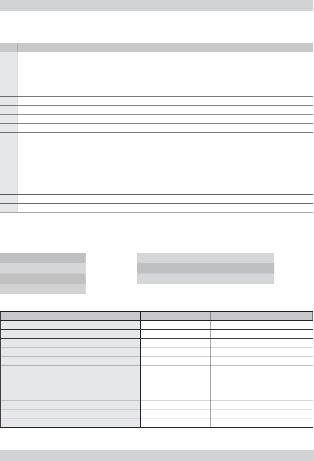
1
. Outer elements
R
emove the water tank, the co
ff
ee container cover, the water dri
p
tra
y
, the co
ff
ee
d
ispenser and the carafe
.
Loosen the screws shown and press inside the slot
$
ZL
WK
D
À
DWKHDG VFUHZGULYH
U
R
em
o
ve the c
o
nnecti
o
n
a
s sh
o
wn
(
connection to the cu
p
heater board
)
123
1) Loosen the screws as shown
2 - 3) Move the cover outwards and press
downwards to release the anchoring teeth
4) Repeat the procedure for all covers
01
A
A
4
ACCADEMIA 07 DISASSEMBLY
GAGGIA Rev. 00 / March 2010 Page / 12
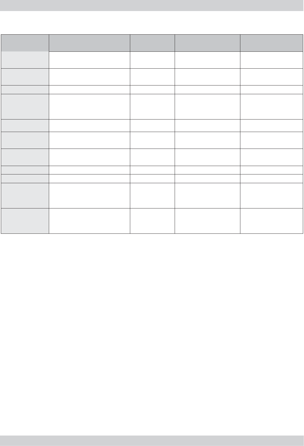
7
.2. Co
ff
ee
g
rinde
r
Loosen the screws as shown and remove the
sound insulating cover of the coffee grinder
Lift the coffee grinder
Remove the connections shown
When reassembling the coffee grinder, make sure
the spring is repositioned correctly (see picture)
LoLo
oo
LL
ee
WW
hh
02
ACCADEMIA 07 DISASSEMBLY
GAGGIA Rev. 00 / March 2010 Page / 12
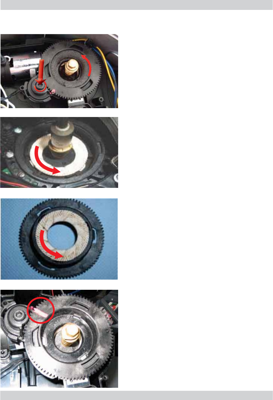
03
Press
d
own on t
h
e grin
d
er a
d
juster an
d
turn t
h
e
u
pper grin
d
er
bl
a
d
e support anti-c
l
oc
k
wise unti
l
it
st
ops.
Turn the grinder blades anticlockwise
f
rom the
suppor
t
.
T
urn the
g
rinder blades clockwise
f
rom the
V
XSSRU
W
7
KH ED\RQH
W
¿
WWLQ
J
VFD
Q
E
H DFFHVVHG
f
rom the rear.
T
h
e two notc
h
es must over
l
ap in or
d
er to a
d
just t
h
e
b
ase
.
7
.3. Grinder blades
ACCADEMIA 07 DISASSEMBLY
GAGGIA Rev. 00 / March 2010 Page / 12
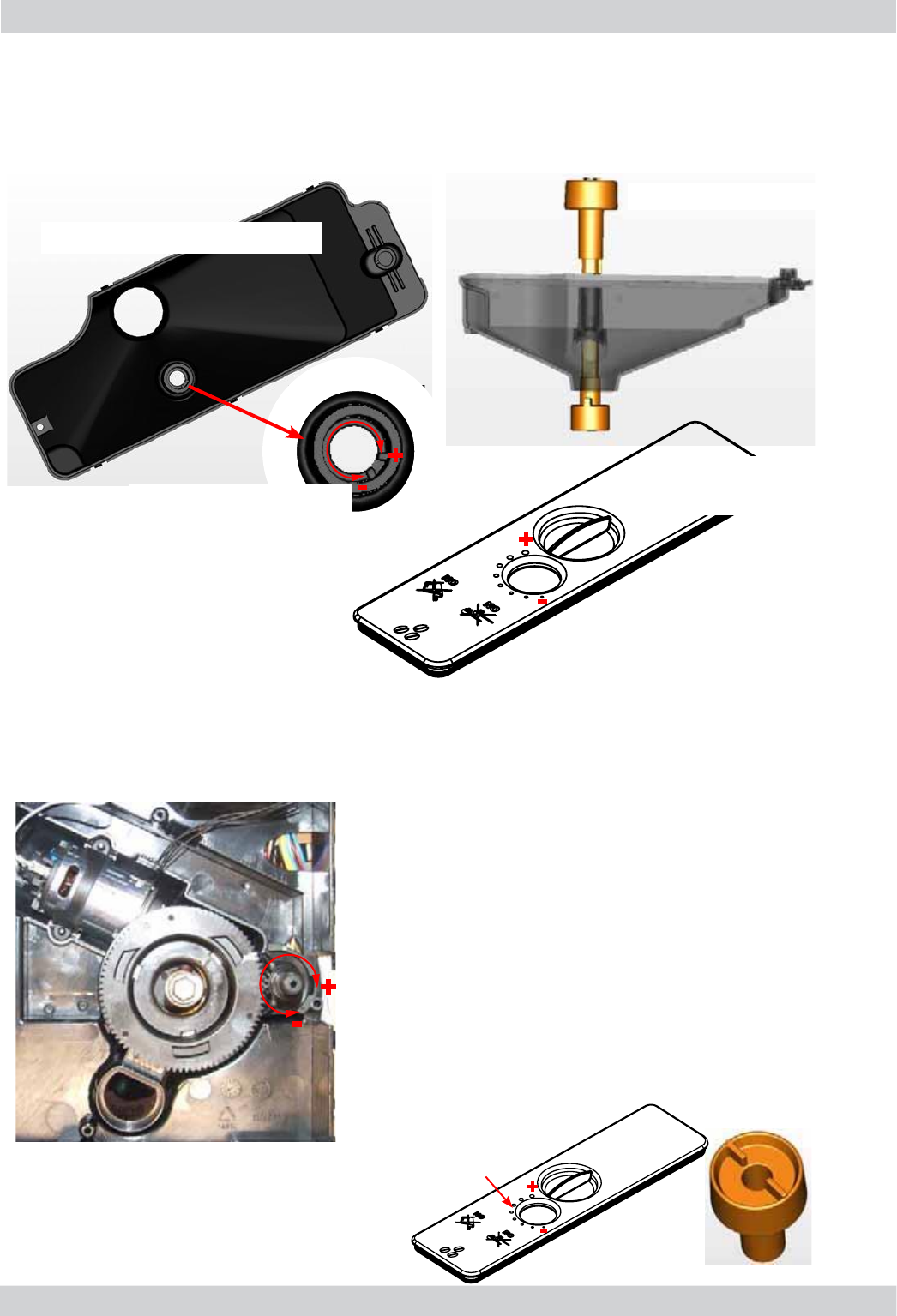
04
7.4. Coffee grinder adjustment
The grinding machine can be adjusted by the user (only with the grinding machine
on) by pressing and turning the knob inside the coffee bean container one notch at
a time
Adjustment implemented by the assistance centres
To further adjust the grinding machine, the
technician can operate directly on the machine by
pressing and turning the highlighted ring nut (C)
(clockwise + to increase the grain size and anti-
clockwise - to decrease it)
If coffee residue is found between the two
grinder blades, it is recommended to adjust this
by tightening a max of two notches at a time.
Lastly, bring the arrow (A) on the adjustment
knob back to the centre of the adjustment dots
on the cover (B).
Coffee bean container
Adjustment knob
A
+
-
C
+
-
B
+
-
Adjustment range
with the knob +
-
Coffee bean
container cover
ACCADEMIA 07 DISASSEMBLY
GAGGIA Rev. 00 / March 2010 Page / 12
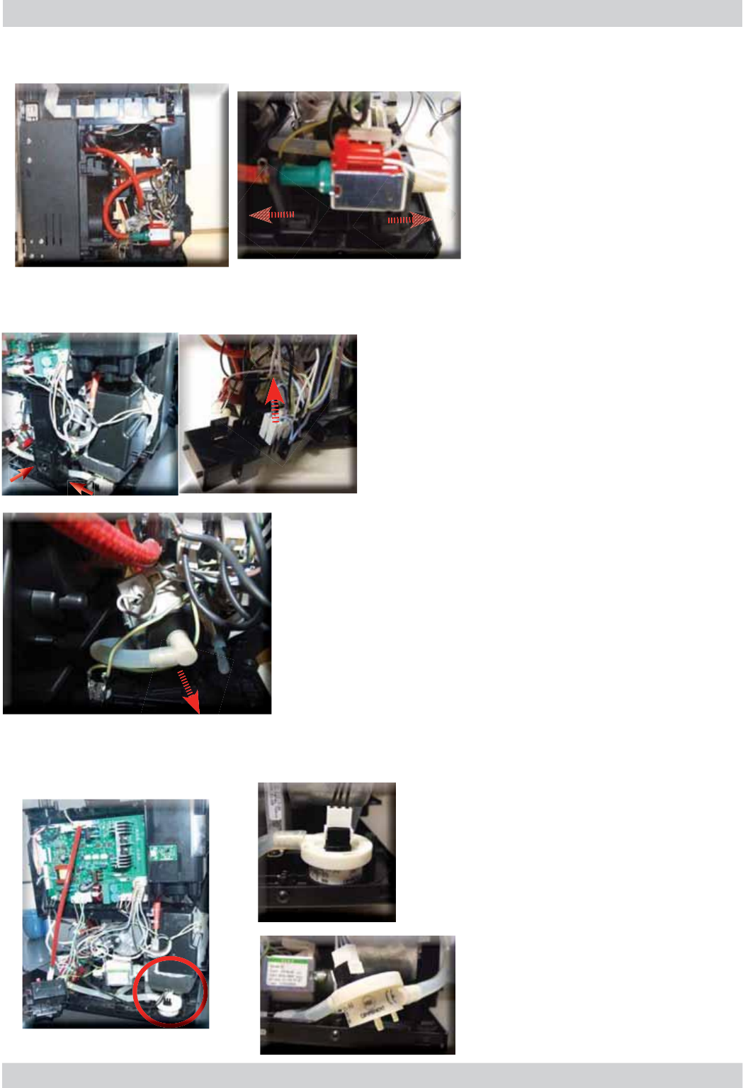
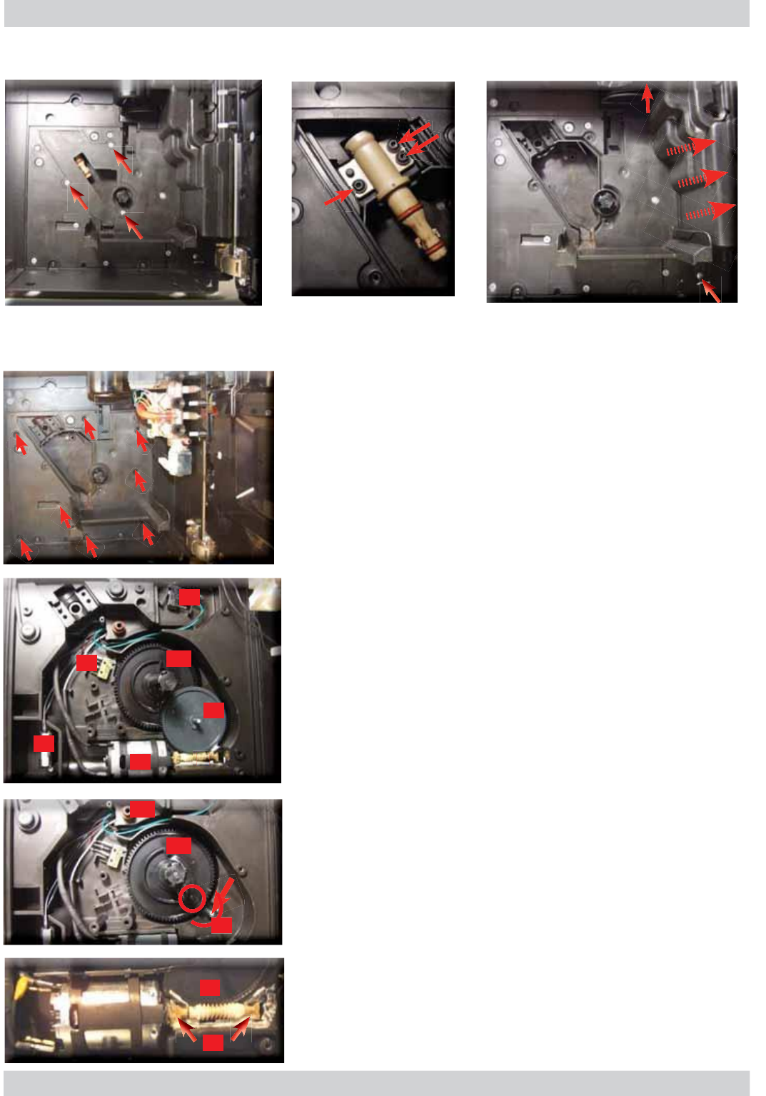
7
.5. Steam pump
7
.
6
. Coffee
p
um
p
7.7.
F
l
ow meter
1) Loosen the screws as shown
2) Remove the connections from the component
support. This process facilitates removing several
components (coffee pump, boiler, etc.)
Remove the two pump supports (highlighted) anchored to
the component support and disconnect the electrical and
water connections
/LIWWKHÀRZPHWHUIURPWKH
component support and remove the
electrical and water connections
Remove the two pump supports
(highlighted) anchored to the
structure and disconnect the
electrical and water connections
2
05
1
ACCADEMIA 07 DISASSEMBLY
GAGGIA Rev. 00 / March 2010 Page / 12
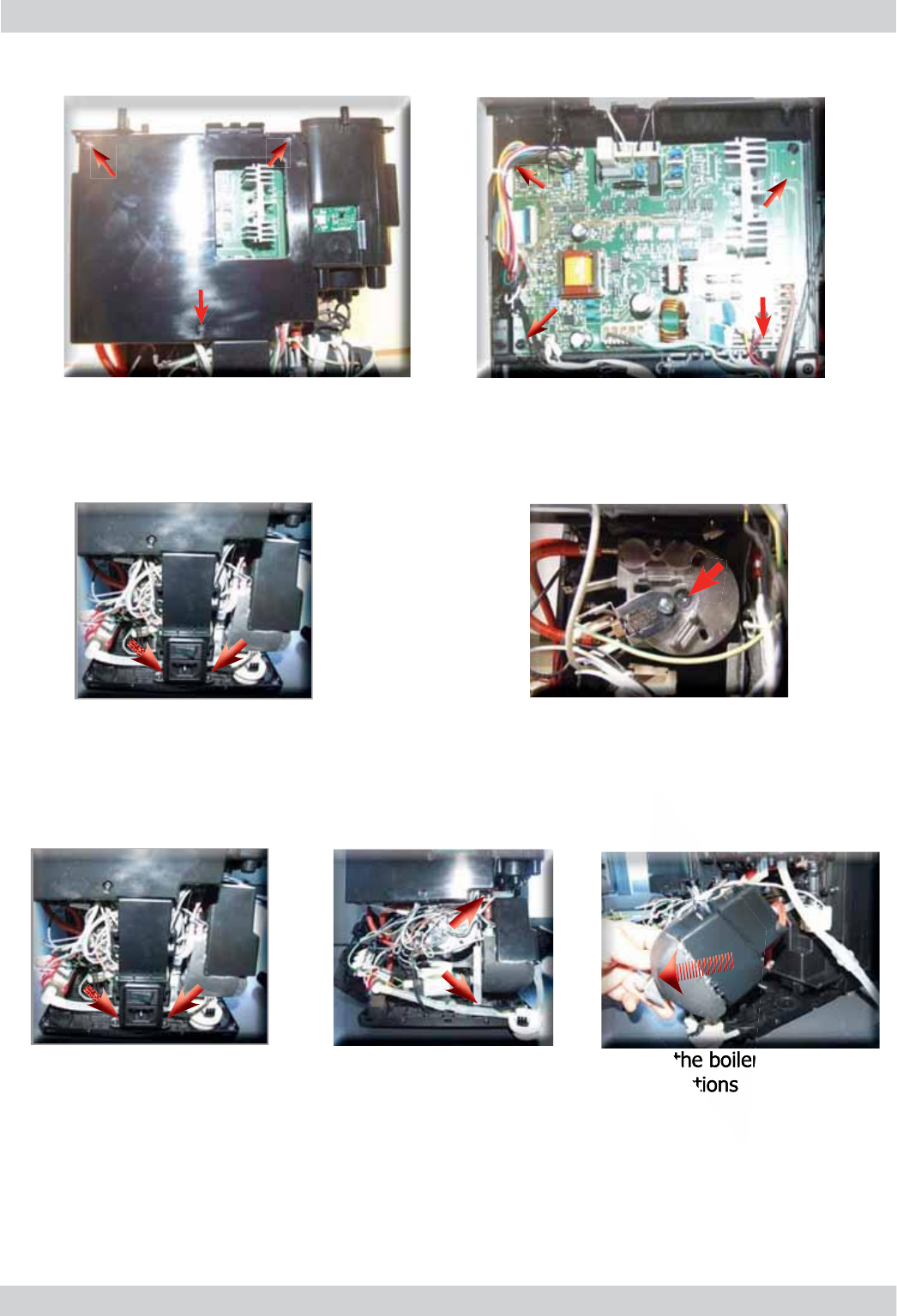
7
.
8
.P
o
wer B
o
ar
d
7
.
9
. Steam b
o
ile
r
7.1
0
. Coffee boiler
2)Loosen the screws as shown and
remove all the electrical connections
1)Loosen the screws as shown and
remove the board cover
Loosen the screw as shown and remove
the electrical and water connections
Remove the screws as shown
and the component support
Remove the screws as shown
and the component support
Loosen the screws as shown, remove the boiler assembly sup-
port and the electrical and water connections
06
ACCADEMIA 07 DISASSEMBLY
GAGGIA Rev. 00 / March 2010 Page / 12
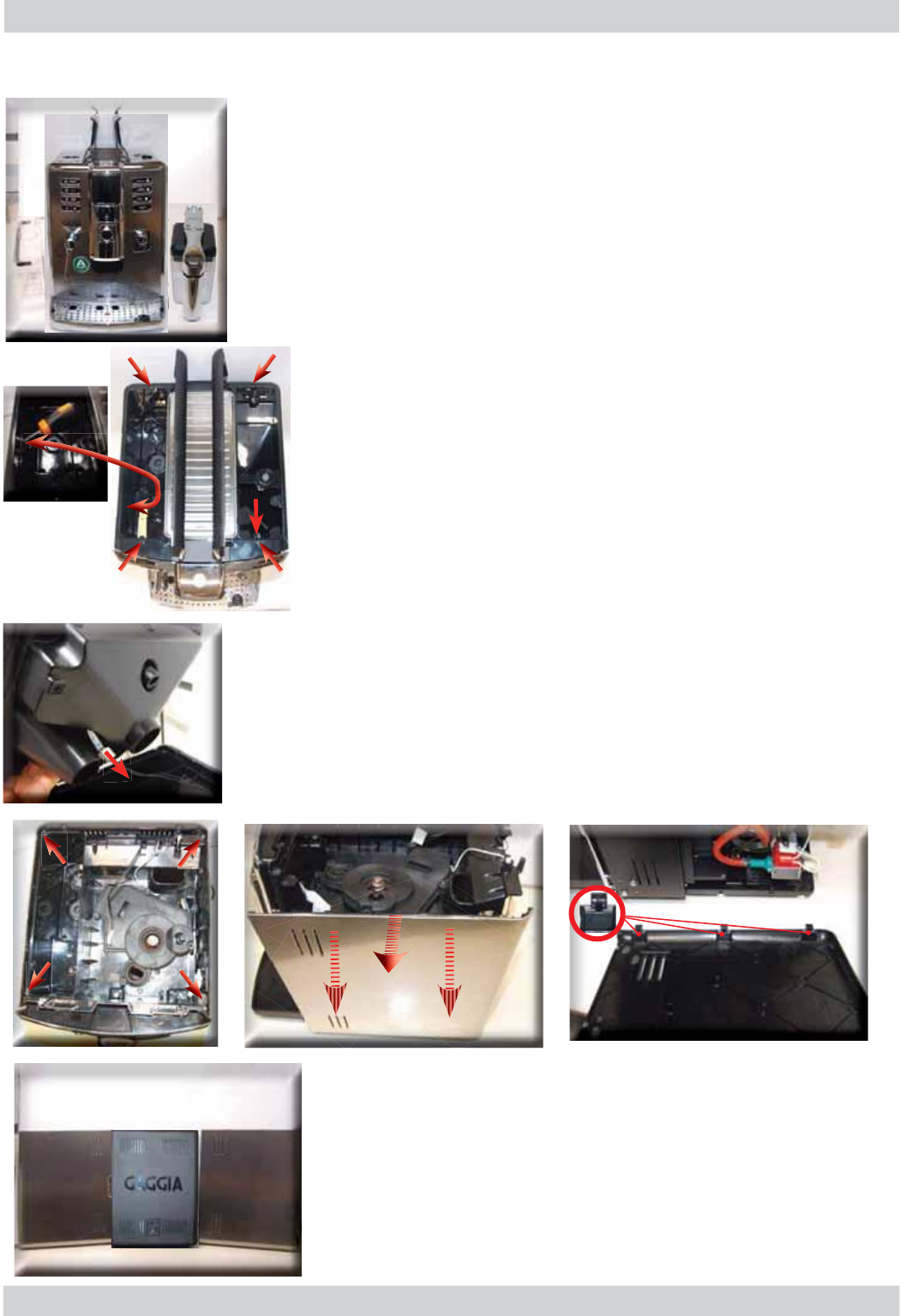
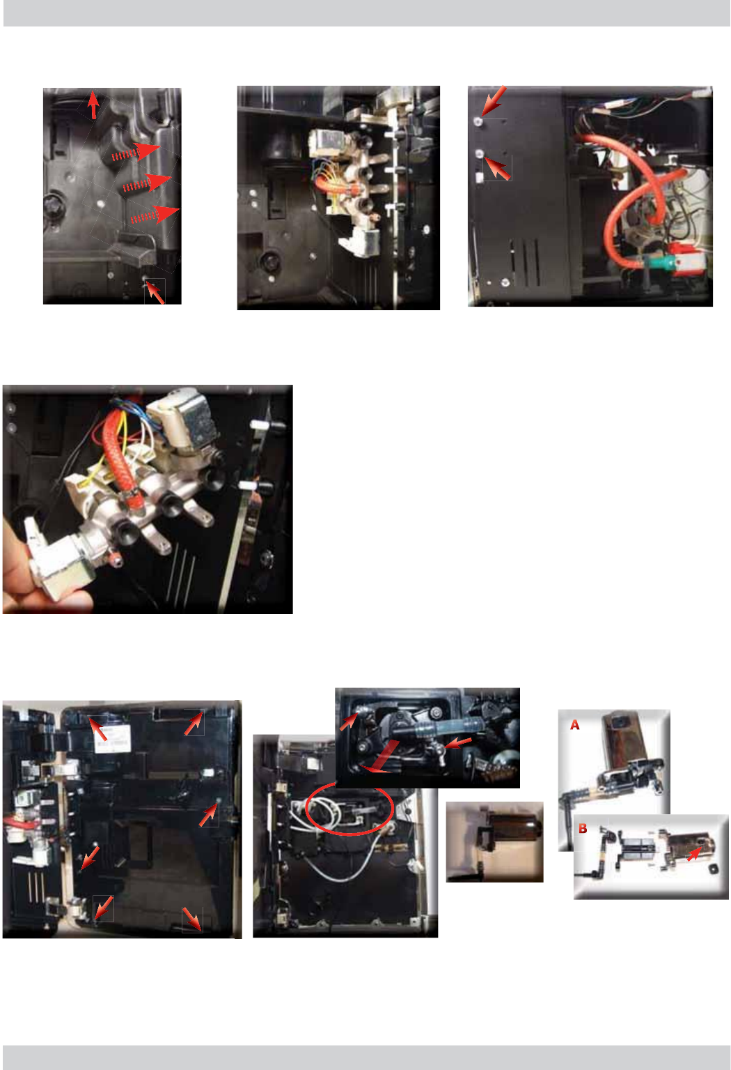
7
.
11
Gearm
o
t
or
Loosen the screws as
shown and remove the
boiler pin
Loosen the screws as shown and
remove the gearmotor cover
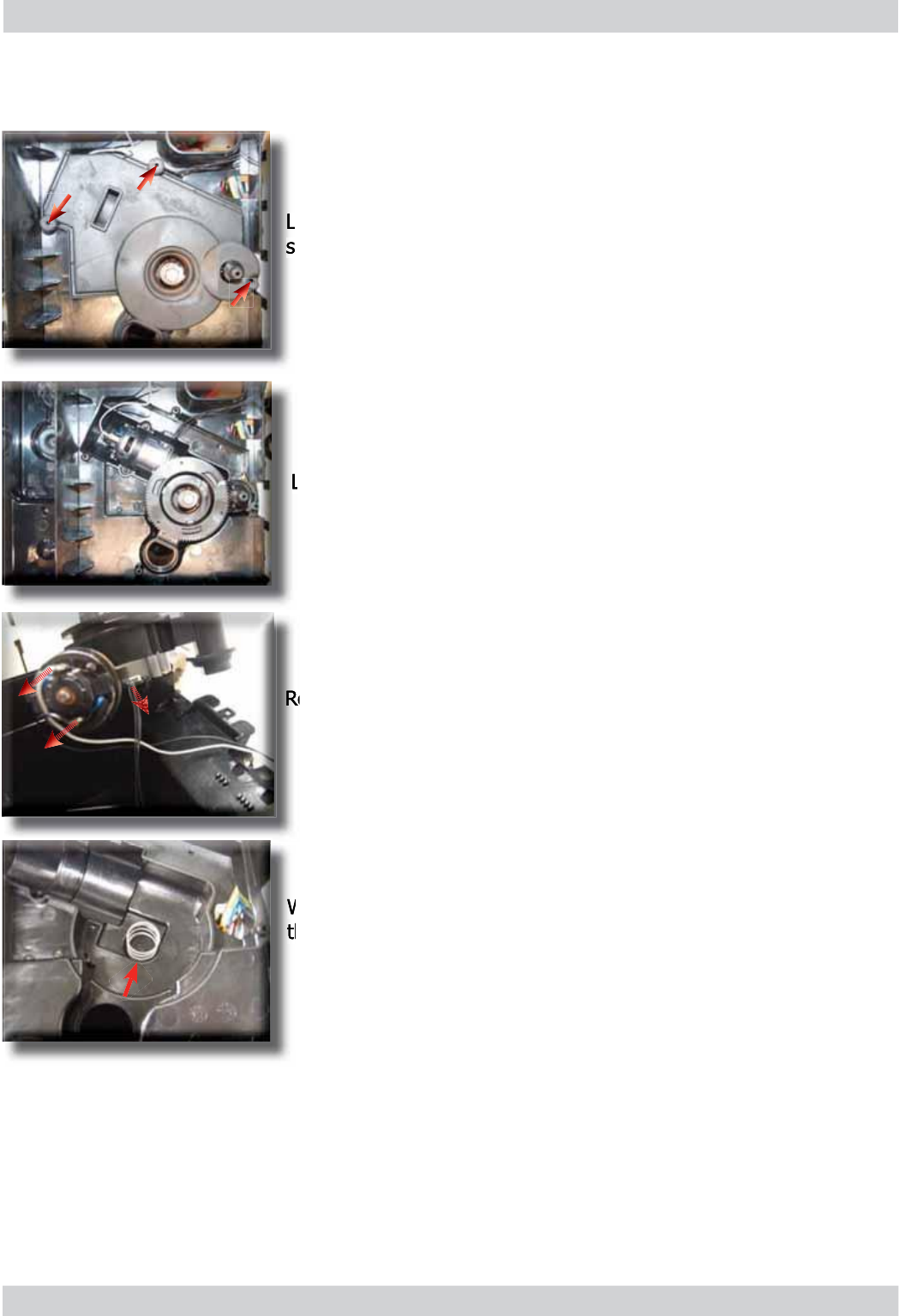
- (G) Drain multi-way valve.
Reconnect t
h
e gear
(
B
)
, ma
k
ing sure t
h
at t
h
e arrow is
a
l
igne
d
wit
h
t
h
e opening t
h
at contains t
h
e pin
(
P
)
.
When re-mounting the motor and the transmission shaft,
ma
k
e sure t
h
e gui
d
es
(
L
)
are inserte
d
in t
h
e correct
h
ousing
.
G
rease the shaft thoroughly and evenly.
The following are located inside the compartment protected
b
y t
h
e casing
:
-
T
h
e e
l
ectric motor
(
A
)
wit
h
gears
(
B
)
an
d
(
C
)
for transmission and timing of the dispensing unit.
-
T
h
e
d
reg
d
rawer presence sensor
(
D
).
-
T
h
e
d
ispensing unit presence microswitc
h
(
E
).
-
The microswitch
(
F
)
that detects the idle
p
hase of the
dispensing unit as well as that of the dispensing process
.
-
Remove t
h
e gear
(
C
)
t
h
at engages wit
h
t
h
e motor
t
r
a
nsmissi
o
n sh
a
ft m
o
t
o
r tr
a
nsmissi
o
n
.
-
Remove t
h
e
l
arge gear
(
B
).
-
Remove the motor
(
A
)
com
p
lete with the transmission shaft.
Loosen the screws as shown and
remove the boiler pin
Loosen the screws as shown and
remove the frothing valve protection
H
L
A
E
B
C
A
D
F
B
G
P
07
ACCADEMIA 07 DISASSEMBLY
GAGGIA Rev. 00 / March 2010 Page / 12
7
.12
.
Frother valve assembly
7
.1
3.
Dis
p
enser assembl
y
Loosen the screws as shown
and remove the frothing valve
protection
Loosen the screws as shown, making sure that the frothing valve does
not fall and damage the connections
Disconnect the electrical and water connections
Loosen the screws as shown to remove
the inner cover of the front panel
Loosen the screws as shown
and remove the coffee dispenser
assembly
Remove the dispenser (picture B)
making sure to reposition the
highlighted spring correctly
08
ACCADEMIA 07 DISASSEMBLY
GAGGIA Rev. 00 / March 2010 Page / 12
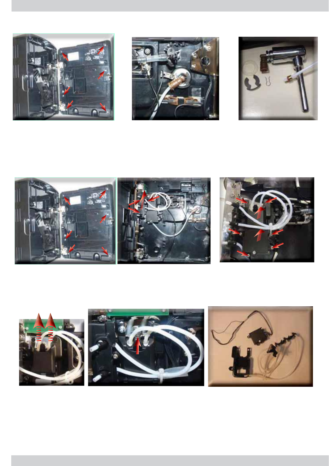
7
.1
4
Steam
p
i
p
e assembl
y
7H
À
RQSLSHVXSSRUWDQGFDUD
I
H
¿
WWLQJDVVHPEO\
Loosen the screws as shown to remove
the inner cover of the front panel
Remove the fork spring and the steam pipe washer and disconnect the
SLSHIURPWKH7HÀRQE\UHPRYLQJWKHIRUN
09
Loosen the screws as shown to remove
the inner cover of the front panel
Loosen the screws as shown
DQGWKH7HÀRQSLSHVXSSRUW
cover from the carafe
5HPRYHWKH7HÀRQSLSH
support assembly
When re-mounting it, make sure to reposition the spring correctly
Loosen the screws shown and
remove the front panel insert
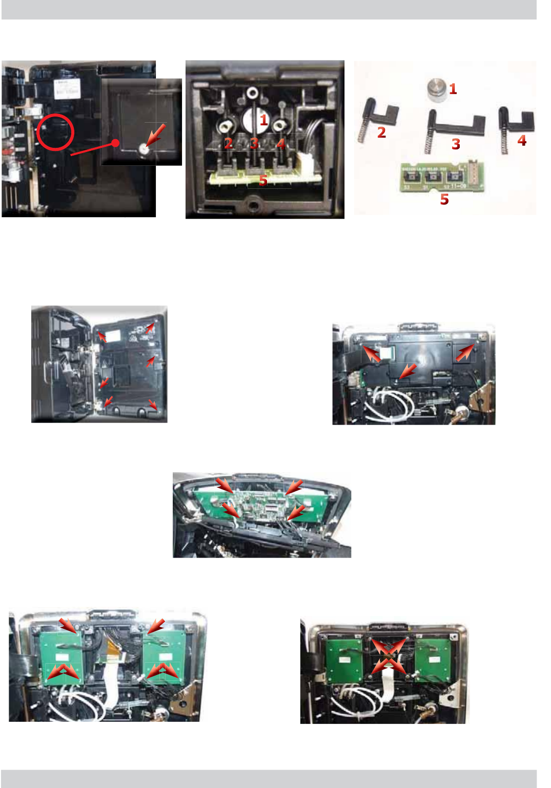
ACCADEMIA 07 DISASSEMBLY
GAGGIA Rev. 00 / March 2010 Page / 12
Loosen the screws as shown to
remove the inner cover of the
front panel
10
7
.1
6
Carafe board
g
eneral assembly
Loosen the screw as shown 1) Magnet to improve carafe adherence to the door
2,3,4) Carafe presence and position sensors
5) Carafe board
7
.1
7
CPU board, dis
p
la
y
and
f
ront
p
ane
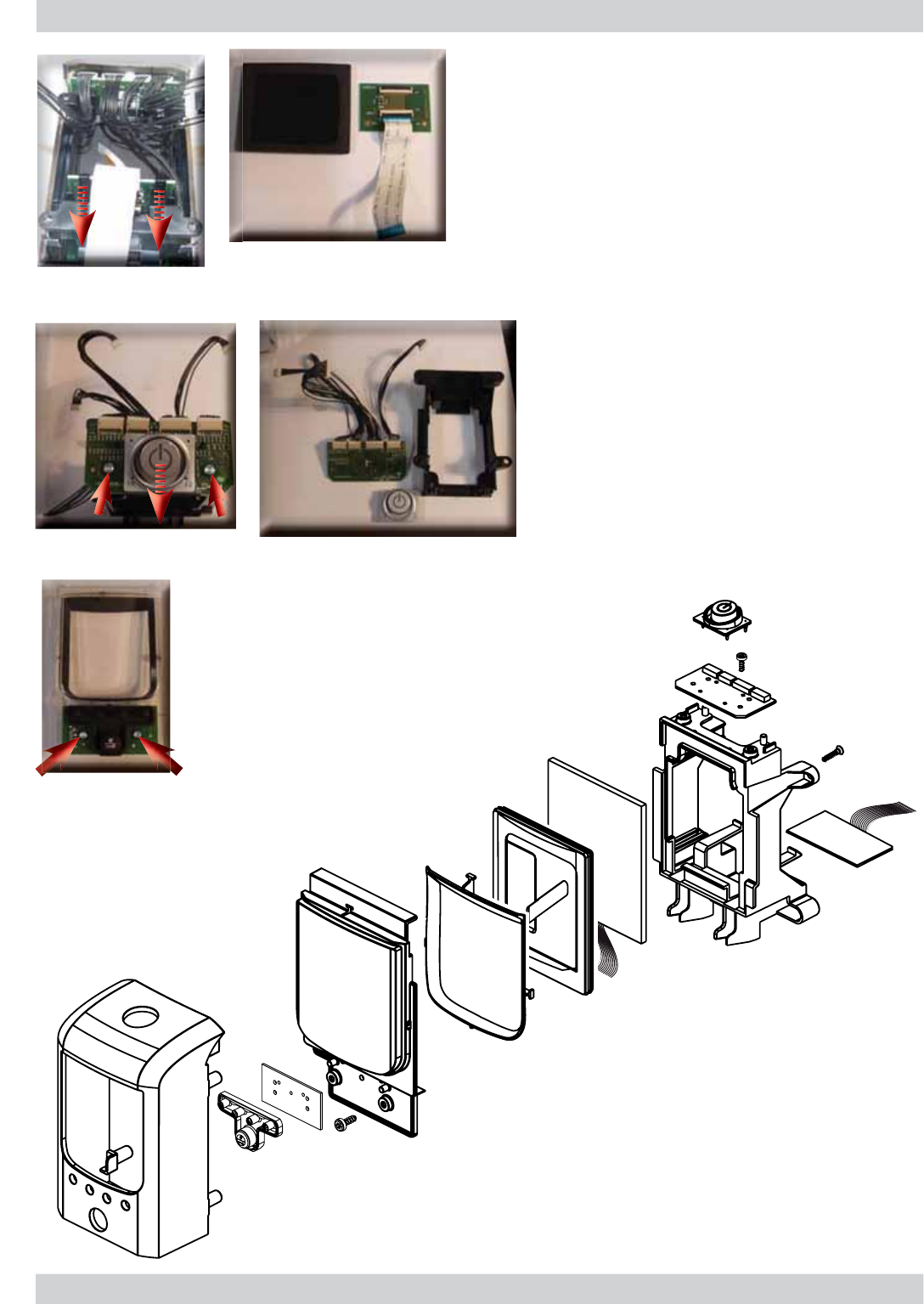
l
Remove the connections, loosen the
screws as shown and remove the CPU
board
Remove the connections, loosen the
screws as shown and remove the board
KBD keyboard
Remove the connections, loosen the
screws as shown and remove the front
panel
Loosen the screws as shown
and remove the CPU board
ACCADEMIA 07 DISASSEMBLY
GAGGIA Rev. 00 / March 2010 Page / 12
11
Remove the Display board by unhooking it from
the support
Loosen the screws as shown to remove the
KBD STAND-BY board
Loosen the screws as shown to
remove the KBD MENU board
Exploded view of the front panel
assembly
ACCADEMIA 07 DISASSEMBLY
GAGGIA Rev. 00 / March 2010 Page / 12
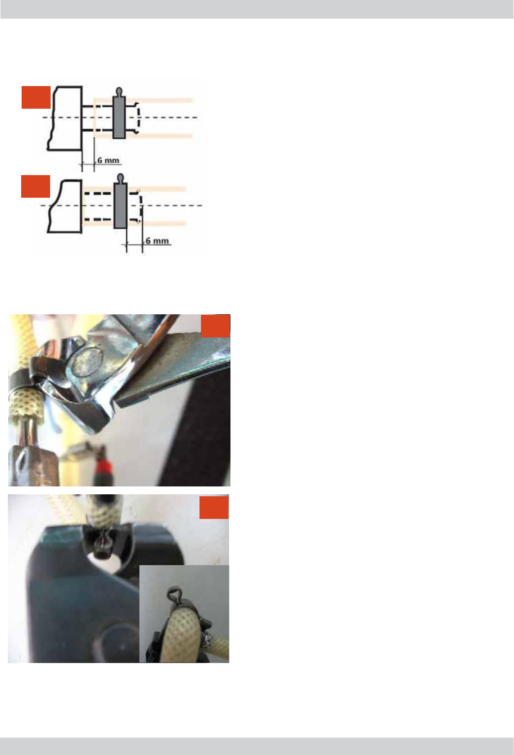
12
1) Boiler connection
2) Other connections
Replacing the pipes
1) Use a suitable pair of pliers to
remove the clamp (as shown in the
picture)
2) Tighten the clamp as shown in the
pictures
7.18. Un/installing Oetiker clamps
1
1
2
2

GAGGIA Rev. 00 / March 2010 ACCADEMIA
CHAPTER 8
NOTES

ACCADEMIA 08 NOTES
GAGGIA Rev. 00 / March 2010 Page / 01
01

GAGGIA Rev. 00 / March 2010 ACCADEMIA
CHAPTER 9
WATER CIRCUIT DIAGRAM
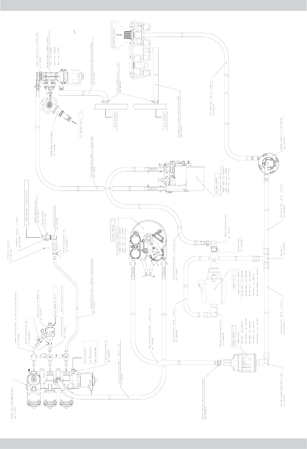
ACCADEMIA 09 WATER CIRCUIT DIAGRAM
GAGGIA Rev. 00 / March 2010 Page / 01
01

GAGGIA Rev. 00 / March 2010 ACCADEMIA
CHAPTER 10
ELECTRICAL DIAGRAM
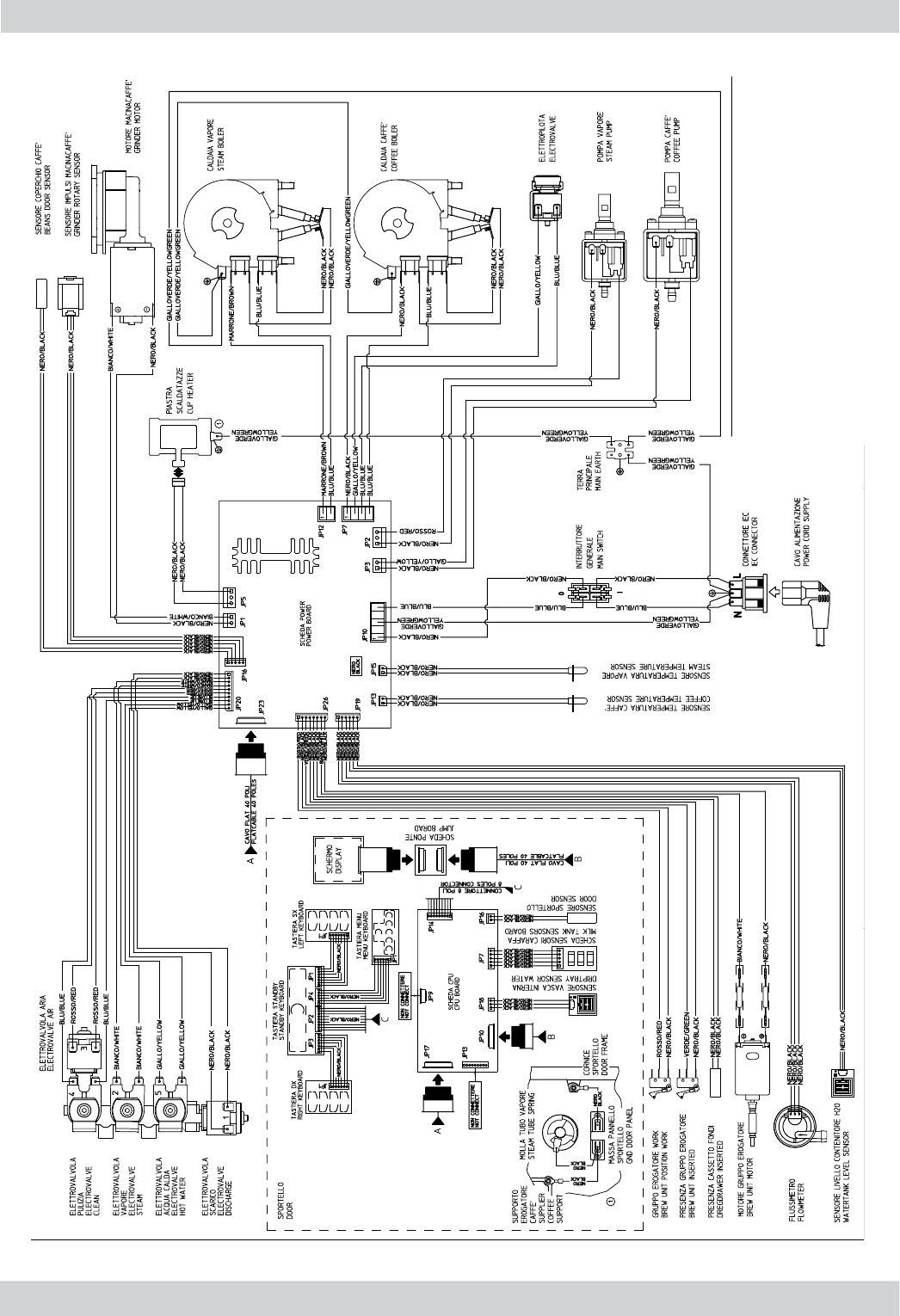
ACCADEMIA 10 ELECTRICAL DIAGRAM
GAGGIA Rev. 00 / March 2010 Page / 01
01
