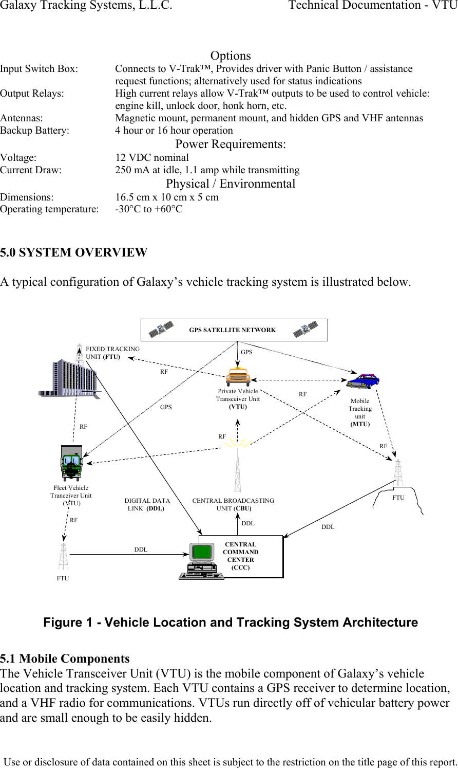
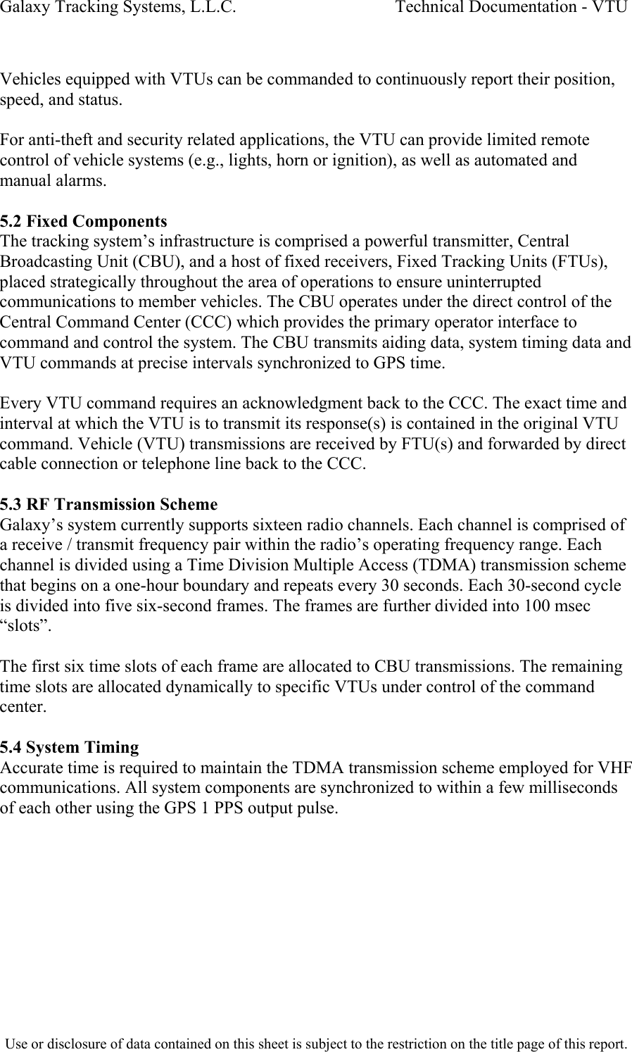
Galaxy Tracking Systems VTRAKH150 VEHICLE TRACKING UNIT User Manual Vehicle Location and Tracking System

Galaxy Tracking Systems L.L.C. VEHICLE TRACKING UNIT Vehicle Location and Tracking System

USERS MANUAL

        Vehicle Location and Tracking System (VLaTS)  Vehicle Transceiver Unit (VTU) User’s Guide  7 Sept 1999       Prepared By:  Galaxy Scientific Corp. 600 Louis Drive Suite 202 Warminster, PA  18974 (215) 672-8005 FAX (215) 672-8708
Table of Contents     1 INTRODUCTION .................................................................................................................................. 6 2 SCOPE ................................................................................................................................................. 6 3 APPLICABLE DOCUMENTS ..............................................................................................................6 4 SPECIFICATIONS ...............................................................................................................................6 5 SYSTEM OVERVIEW ..........................................................................................................................7 5.1 MOBILE COMPONENTS........................................................................................................................ 7 5.2 FIXED COMPONENTS .......................................................................................................................... 8 5.3 RF TRANSMISSION SCHEME ............................................................................................................... 8 5.4 SYSTEM TIMING.................................................................................................................................. 8 6 VTU COMPONENTS............................................................................................................................ 9 6.1 VTU SYSTEM ENCLOSURE ................................................................................................................. 9 6.1.1 GPS Receiver.......................................................................................................................... 9 6.1.2 Radio .......................................................................................................................................9 6.1.3 System Controller.................................................................................................................... 9 6.2 ANTENNAS AND CABLES ................................................................................................................... 10 6.3 OPTIONAL COMPONENTS ..................................................................................................................10 6.3.1  Switch Box (Alarms and Indicators) ...................................................................................... 10 6.3.2 Relay Box (Vehicle Controls) ................................................................................................ 10 7  VTU CONNECTORS AND CONNECTIONS ..................................................................................... 11 7.1 INPUTS.............................................................................................................................................13 7.2 OUTPUTS .........................................................................................................................................14 8 VTU OPERATIONS............................................................................................................................14 8.1 VTU STARTUP .................................................................................................................................14 8.2 VTU OPERATING MODES .................................................................................................................15 8.2.1  OUT OF SERVICE Operating Mode ..................................................................................... 15 8.2.2 IN SERVICE Operating Mode ............................................................................................... 15
Table of Figures    Figure 1 - Vehicle Location and Tracking System Architecture ....................................... 7 Figure 2 - Vehicle Transceiver Unit (VTU)....................................................................... 9 Figure 3 VTU INPUT PIN DEFINITIONS - 10 pin BROWN Molex Connector ............... 11 Figure 4 VTU POWER CONNECTOR PIN DEFINITIONS - 4 pin WHITE Molex Connector .............................................................................................................. 12 Figure 5 VTU OUTPUT PIN DEFINITIONS - 8 pin BROWN Molex Connector ............. 13
Galaxy Tracking Systems, L.L.C.                                    Technical Documentation - VTU  1.0 INTRODUCTION  This document is intended to provide a description of the operation and interfaces of the Vehicle Transceiver Unit (VTU.  2.0 SCOPE  This document describes  the operation and use of the Vehicle Transceiver Unit (VTU).   3.0 APPLICABLE DOCUMENTS Vehicle Location and Tracking System (VLaTS) Vehicle Tracking Unit (VTU) Installation Guide Revision 1 24 February 1999  Vehicle Location and Tracking System (VLaTS) Mobile Tracking Unit (MTU) User’s Guide 7 Sept 1999  4.0 Specifications VHF Receiver: Frequency:     Multiple frequency operation within band Frequency Band:    150 - 174 MHz band typical Modulation Format:   GMSK Deviation:     +/-1.5 kHz Transmission Rate:   9,600 Baud, 7-bit even parity, 1 stop bit (12.5 kHz BW) Sensitivity:     -114 dBm VHF Transmitter: Frequency:     Multiple frequency operation within band Frequency Band:    150 - 174 MHz band typical Internal Stability:   +/- 1.5 ppm Modulation Format:   GMSK Deviation:     +/- 1.5 kHz Transmission Rate:   9,600 Baud, 7-bit even parity, 1 stop bit (12.5 kHz BW) Transmit Power:    2.0 Watts (at 13.5 VDC) Harmonic Suppression:   >50 dBc GPS Receiver: Update rate:     1 Hz Position Accuracy:   2m 2D RMS with Differential GPS (included) 100 m 2D RMS when Differential not available Velocity Accuracy:   0.1 m/sec Time Accuracy:     130 ns w/ SA on Acquisition Time:   Hot Start: < 3 seconds Warm Start:     < 20 seconds Cold Start:     < 2 minutes Number of Channels:   12 (All-in-View) Inputs / Outputs Inputs:       4 Discrete Switch Inputs Outputs:     4 Discrete Outputs, 15 mA  Use or disclosure of data contained on this sheet is subject to the restriction on the title page of this report.
Galaxy Tracking Systems, L.L.C.                                    Technical Documentation - VTU   Options Input Switch Box:   Connects to V-Trak™, Provides driver with Panic Button / assistance request functions; alternatively used for status indications Output Relays:     High current relays allow V-Trak™ outputs to be used to control vehicle: engine kill, unlock door, honk horn, etc. Antennas:     Magnetic mount, permanent mount, and hidden GPS and VHF antennas Backup Battery:     4 hour or 16 hour operation Power Requirements: Voltage:     12 VDC nominal Current Draw:     250 mA at idle, 1.1 amp while transmitting Physical / Environmental Dimensions:     16.5 cm x 10 cm x 5 cm Operating temperature:   -30°C to +60°C      5.0 SYSTEM OVERVIEW  A typical configuration of Galaxy’s vehicle tracking system is illustrated below.   CENTRALCOMMANDCENTER(CCC)CENTRALCOMMANDCENTER(CCC)CENTRAL BROADCASTING               UNIT (CBU)GPS SATELLITE NETWORKFIXED TRACKING UNIT (FTU)FTUFTU    DIGITAL DATA       LINK  (DDL)DDL DDLDDLPrivate VehicleTransceiver Unit(VTU)MobileTrackingunit(MTU)RFRFRFRFRFFleet VehicleTranceiver Unit (VTU)GPSGPSRF Figure 1 - Vehicle Location and Tracking System Architecture  5.1 Mobile Components The Vehicle Transceiver Unit (VTU) is the mobile component of Galaxy’s vehicle location and tracking system. Each VTU contains a GPS receiver to determine location, and a VHF radio for communications. VTUs run directly off of vehicular battery power and are small enough to be easily hidden.  Use or disclosure of data contained on this sheet is subject to the restriction on the title page of this report.
Galaxy Tracking Systems, L.L.C.                                    Technical Documentation - VTU   Vehicles equipped with VTUs can be commanded to continuously report their position, speed, and status.  For anti-theft and security related applications, the VTU can provide limited remote control of vehicle systems (e.g., lights, horn or ignition), as well as automated and manual alarms.  5.2 Fixed Components The tracking system’s infrastructure is comprised a powerful transmitter, Central Broadcasting Unit (CBU), and a host of fixed receivers, Fixed Tracking Units (FTUs), placed strategically throughout the area of operations to ensure uninterrupted communications to member vehicles. The CBU operates under the direct control of the Central Command Center (CCC) which provides the primary operator interface to command and control the system. The CBU transmits aiding data, system timing data and VTU commands at precise intervals synchronized to GPS time.  Every VTU command requires an acknowledgment back to the CCC. The exact time and interval at which the VTU is to transmit its response(s) is contained in the original VTU command. Vehicle (VTU) transmissions are received by FTU(s) and forwarded by direct cable connection or telephone line back to the CCC.   5.3 RF Transmission Scheme Galaxy’s system currently supports sixteen radio channels. Each channel is comprised of a receive / transmit frequency pair within the radio’s operating frequency range. Each channel is divided using a Time Division Multiple Access (TDMA) transmission scheme that begins on a one-hour boundary and repeats every 30 seconds. Each 30-second cycle is divided into five six-second frames. The frames are further divided into 100 msec “slots”.  The first six time slots of each frame are allocated to CBU transmissions. The remaining time slots are allocated dynamically to specific VTUs under control of the command center.  5.4 System Timing Accurate time is required to maintain the TDMA transmission scheme employed for VHF communications. All system components are synchronized to within a few milliseconds of each other using the GPS 1 PPS output pulse.  Use or disclosure of data contained on this sheet is subject to the restriction on the title page of this report.
Galaxy Tracking Systems, L.L.C.                                    Technical Documentation - VTU   VTU Components    GPS S ubsys tem (GPS Receiver) Digital B ase ba nd  Subsyst em  (Micro Controller)  p,v,t  ID, stat us  Communications  Subsyst em  (Radio Modem) Packets ,  Timing data /  control  Feat ur es  3 Freq  b etwee n  (450-470 Mhz) 9600 ba ud GMSK mod ulati on Forward Error Correction (Hamming code, Data  Interleaving)  2 watt  tr ansm it  power  20 K  ran ge GPS VLaTS Vehicle Tracking Unit (VTU) p,v,t,  ID,st atus Com mands,  Timing Stat us I nclu des:  H ardware st atus  GPS Tracki ng s tat us  Discretes status  Config urati on,  Initialization, GPS Correcti ons  Vehicl e  Movement, SOS,  Assistanc e,  Car Alarm Unaut horiz ed Mov ement  Arm ed,  SOS,  Assistanc e  Discretes  Indic ators  UHF   Figure 2 - Vehicle Transceiver Unit (VTU)  6.1 VTU System Enclosure  6.1.1 GPS Receiver Every VTU contains a GPS receiver and is equipped with a GPS antenna and an antenna cable. The receiver is differentially aided through the RF link to provide vehicle position accuracy to within a few meters and synchronized system time accurate to within .5 ms. The position information is transmitted to the command center at a precise predetermined moment based on system time.  The GPS receiver will report a position at 0 degrees latitude and 0 degrees longitude unless it can find and track GPS satellites. This takes less than a minute under normal circumstances.  6.1.2 Radio The VTU radio is capable of operation on 16 distinct frequencies over the frequency range of 150 to 174 MHz at 2 watts. Frequencies are preset at the factory and selected for operation from the command center via the RF link.  6.1.3 System Controller The system controller is the heart of the VTU. It integrates the radio and GPS, contains the system logic the overall operation of the VTU. It is comprised of a single board  Use or disclosure of data contained on this sheet is subject to the restriction on the title page of this report.
Galaxy Tracking Systems, L.L.C.                                    Technical Documentation - VTU  embedded controller equipped with a Motorola M68HC11E1 microcontroller, 32 Kilobytes of flash ROM, 32 Kilobytes of SRAM and various support components to enable the circuitry to perform the desired tasks.  In addition, the baseband board is equipped with a MX-COM 909A single chip GMSK data pump modem for the purpose of providing the communications subsystem with modulation and Forward Error Correction (FEC) for data transmission and reception.  6.2 Antennas and Cables A GPS Antenna, a UHF antenna, associated cables and power cabling are included with each VTU. GPS antennas are available as permanently mounted units, temporary magnetic mount units or as covert units. Similar options are available for UHF antennas. Refer to the VTU Installation Guide details.  6.3 Optional Components  6.3.1 Switch Box (Alarms and Indicators) As an option, a small switch box can be acquired for installation in VTU equipped vehicles. The box houses the three momentary contact switches for issuing alarms and arming the unauthorized movement sensor and four LED indicators. Three of the indicators display alarm status, the fourth monitors VTU power and transmit activity.  The switch box is small enough that it can be mounted unobtrusively in the passenger compartment in such a way that the operator can monitor status, but it will go unnoticed by other occupants (or a thief).  6.3.2 Relay Box (Vehicle Controls)  The VTU provide four outputs suitable for controlling relays. With the relays installed in various automotive systems, lights, horn, ignition, etc. the VTU can be controlled or disabled by suitably equipped chase vehicles. Refer to the Mobile Tracking Unit (MTU) User’s Guide.  This type of installation is very model or even vehicle specific and is ordinarily left to qualified mechanics or motor pool personnel.  Use or disclosure of data contained on this sheet is subject to the restriction on the title page of this report.
Galaxy Tracking Systems, L.L.C.                                    Technical Documentation - VTU   7.0 VTU Connectors and Connections  Figure 3 VTU INPUT PIN DEFINITIONS - 10 pin BROWN Molex Connector  Pin Function 10  DO NOT CONNECT, UNIT MAY BE DAMAGED BY ANY CONNECTION TO THIS PIN 9 Ground 8  DO NOT CONNECT, UNIT MAY BE DAMAGED BY ANY CONNECTION TO THIS PIN 7  DO NOT CONNECT, UNIT MAY BE DAMAGED BY ANY CONNECTION TO THIS PIN 6  DO NOT CONNECT, UNIT MAY BE DAMAGED BY ANY CONNECTION TO THIS PIN 5 NO CONNECTION 4  Input, Alarm Discrete--connect to ground (pin 9) to activate 3  Input, Unauthorized Movement Discrete--connect to ground (pin 9) to activate 2  Input, Roadside Assistance request Discrete--connect to ground (pin 9) to activate 1  Input, SOS Input Discrete--connect to ground (pin 9) to activate  Use or disclosure of data contained on this sheet is subject to the restriction on the title page of this report.
Galaxy Tracking Systems, L.L.C.                                    Technical Documentation - VTU   Figure 4 VTU POWER CONNECTOR PIN DEFINITIONS - 4 pin WHITE Molex Connector  Pin Function 1 Chassis Ground 2            VCC +12V 3 No Connection 4  Ignition Sense-- +12V if engine on/ 0 V if off  Use or disclosure of data contained on this sheet is subject to the restriction on the title page of this report.
Galaxy Tracking Systems, L.L.C.                                    Technical Documentation - VTU   Figure 5 VTU OUTPUT PIN DEFINITIONS - 8 pin BROWN Molex Connector   Pin Function 1  Power / Transmit LED (Connect anode of LED to this pin, cathode to pin 9 of the 10 pin Molex or other ground point) Illuminates when unit is powered, blinks off during transmit. 2  Unauthorized Movement Indicator LED (Connect cathode of LED to this pin, anode through 500 ohm resistor to 12V) 3  Roadside Assistance request Indicator LED (Connect cathode of LED to this pin, anode through 500 ohm resistor to 12V) 4  SOS Indicator LED (Connect cathode of LED to this pin, anode through 500 ohm resistor to 12V) 5  Engine Disable Relay control—Inactive: 0V.  Active: 5V to shut off engine.  WARNING, This output can only provide 20 ma of current.  Drawing more than 20 ma at this pin will destroy the device.  There MUST be a current amplification device at this output to drive the relay. 6  Signal Light Relay control—Inactive: 0V.  Active:  oscillates to 0 to 5V to flash signal lights. WARNING, This output can only provide 20 ma of current.  Drawing more than 20 ma at this pin will destroy the device.  There MUST be a current amplification device at this output to drive the relay. 7  Horn Relay control—Inactive: 0V.  Active:  oscillates 0 to 5V to honk horn. WARNING, This output can only provide 20 ma of current.  Drawing more than 20 ma at this pin will destroy the device.  There MUST be a current amplification device at this output to drive the relay. 8  Headlights Relay control—Inactive: 0V.  Active:  oscillates 0 to 5V to flash headlights. WARNING, This output can only provide 20 ma of current.  Drawing more than 20 ma at this pin will destroy the device.  There MUST be a current amplification device at this output to drive the relay.  The VTU is equipped with a total of four inputs (J2) and eight outputs (J1).  7.1 Inputs Three of the inputs (pins 1-3 on J2) interface to the Switch Box option. The functions currently served by these connections are SOS, request for roadside assistance and arming of the unauthorized movement sensor. A momentary contact switch is provided on the Switch Box for each of the three inputs. When pressed, two of the switches issue silent alarms (SOS, Assistance) and the third toggles the unauthorized movement sensor  Use or disclosure of data contained on this sheet is subject to the restriction on the title page of this report.
Galaxy Tracking Systems, L.L.C.                                    Technical Documentation - VTU  between the armed and disarmed states. The remaining input is used to sense activation of the vehicle alarm system (if present).  7.2 Outputs Each of the three Switch Box switches have an associated status LED output (pins 5-7 on J1). When one of the silent alarm switches is pressed, the corresponding LED will flash at a 1 Hz rate to indicate an alarm has been sent to the command center. When the alarm is acknowledged, the LED lights continuously. The LED can only be extinguished (and the alarm cleared) from the command center. The third LED is lit when the unauthorized movement sensor is armed.  The fourth output (pin 8) drives an LED that indicates VTU power and blinks off whenever the VTU transmits.  The remaining four outputs (pins 4, 5, 6 and 7) can drive small loads (<20mA) and must be interfaced to real world circuits through high current drivers (MOSFETS) or relays.  These outputs are dedicated to the control of external devices such as vehicle accessories, horns, etc.   8.0 VTU Operations  8.1 VTU Startup The VTU initializes first time power is applied after installation. Most importantly, the GPS receiver must find and track satellites, compute its position and synchronize to GPS time. A clear view of the sky and the GPS satellite constellation is required to do this. If the vehicle is parked in a garage or is shaded from the sky, it should be moved to a location with an unobstructed view of the sky. The vehicle SHOULD REMAIN STATIONARY until the GPS receiver has had time to initialize (30 minutes or less).  It is absolutely imperative that GPS initialize properly. All VTU and CBU communications are synchronized to GPS time. An unsynchronized VTU may transmit within some other VTU’s time slot (in which case both VTUs seem to disappear) or may not transmit at all.  To verify that the VTU is ready for use, a series of commands are issued form the command center. A number of ONE-SHOT commands are transmitted first. A ONE SHOT requests a single response from the VTU no matter what its operating mode. Any response from the VTU verifies the communication link and that VTU time keeping via GPS has been established.  Next the VTU is commanded to IN SERVICE mode. Proper initialization of the VTU is indicated when the correct time, GPS tracking status and position are returned to the command center in the IN SERVICE response. If the status is not correct, additional ONE-SHOT commands are transmitted to the VTU until the responses (IN SERVICE messages) indicate that initialization is complete. At this point the VTU is ready for use.  Use or disclosure of data contained on this sheet is subject to the restriction on the title page of this report.
Galaxy Tracking Systems, L.L.C.                                    Technical Documentation - VTU   Once the VTU has been initialized the first time, it will be able to reinitialize within a minute unless it has been disconnected from vehicle battery power for a long period of time (greater than a week).  8.2 VTU Operating Modes The VTU operates in one of two modes, IN SERVICE or OUT OF SERVICE. In either mode, the VTU receives commands over the UHF radio link from the command center. The VTU confirms each command by responding with either an IN SERVICE or OUT OF SERVICE message.  Commanded settings and status are maintained through power outages.  8.2.1 OUT OF SERVICE Operating Mode The VTU is factory configured to begin life in the OUT OF SERVICE operating mode. OUT OF SERVICE is a standby mode that is also used to verify unit communications. While in this mode, the VTU will transmit an OUT OF SERVICE response to all commands except the IN SERVICE command.  When OUT OF SERVICE, all in-vehicle alarms are disabled, (see SELF-ACTIVATION).  8.2.1.1 OUT OF SERVICE Operating Mode Commands The commands available with OUT OF SERVICE follow.  IN SERVICE Command Upon receipt of an IN SERVICE command, the VTU will change operating mode to IN SERVICE and transmit an IN SERVICE message to report the change in mode. The VTU is set operational by this command and can begin to report position, time, status and on-board alarms.  8.2.2 IN SERVICE Operating Mode When commanded IN SERVICE, the VTU will respond with a single IN SERVICE message at the exact time indicated in the command packet. While IN SERVICE, the VTU transmits an IN SERVICE message in response to all commands. The VTU will also transmit an IN SERVICE message in response to alarms activated by the vehicle operator (e.g., SOS) or events (e.g., unauthorized movement).  8.2.2.1IN SERVICE Operating Mode Commands The commands available with IN SERVICE follow.  OUT OF SERVICE The VTU will change operating mode to OUT OF SERVICE and transmit an OUT OF SERVICE message to report the change in mode. On-board alarms are disabled. All subsequent commands (except IN SERVICE) are answered with an OUT OF SERVICE message.  Use or disclosure of data contained on this sheet is subject to the restriction on the title page of this report.
Galaxy Tracking Systems, L.L.C.                                    Technical Documentation - VTU   ONE SHOT The one-shot command is a request for a single position / status report. The VTU responds with a single IN SERVICE message containing current status, position, speed and time.  ACTIVATE TRACKING The ACTIVATE TRACKING command causes the VTU to begin regular position reporting. The rate and the exact moment at which the VTU reports and the frequency on which the report is transmitted are all contained in the command. Tracking mode is used to monitor vehicle movements and status in real-time and to vector pursuit vehicles to intercept points.  DEACTIVATE TRACKING Position reporting ceases when DEACTIVATE TRACKING is commanded. The VTU responds with one last IN SERVICE message to indicate the change in tracking status. Commanding the VTU OUT OF SERVICE also stops tracking reports, however, in this case, the VTU responds with a single OUT OF SERVICE message to report its change in operating mode.  POLL REQUEST  The POLL REQUEST equivalent to issuing a ONE SHOT to every member a group (fleet) of vehicles. Upon receipt of a POLL REQUEST each VTU will compare the transmitted poll information to poll classes defined internally. If there is a match, the VTU will transmit an IN SERVICE message at the frequency and in the time slot specified in the matching poll class. Poll classes are factory configured to allow low priority status reporting for large groups of related vehicles.  Poll responses are low priority. If the VTU is responding to a command or a self-activation the poll request is ignored. A scheduled poll response is automatically canceled if the VTU receives a command packet or self-activates.  Polls do not extend beyond the end of the 30-second cycle in which the poll was requested. If the VTU schedules a poll response, it will ignore any new poll packets until the scheduled poll response completes.   SELF ACTIVATION (SOS) A vehicle (VTU) does not report its position on a regular basis until it is commanded to ACTIVATE by the command center. In emergency situations, however, the VTU can request to begin regular position reporting in order to be tracked by “SELF ACTIVATING”.  The conditions that can result in SELF-ACTIVATIONS are SOS, request for roadside assistance, unauthorized movement and vehicle alarm. SOS and the roadside assistance requests are initiated when the operator depresses a switch (if equipped with the switch box option). If the operator has armed the VTU motion sensor (included in the switch box  Use or disclosure of data contained on this sheet is subject to the restriction on the title page of this report.
Galaxy Tracking Systems, L.L.C.                                    Technical Documentation - VTU   Use or disclosure of data contained on this sheet is subject to the restriction on the title page of this report.  option), movement of the vehicle beyond a few hundred feet or at speeds in excess of 20 KPH will trigger a SELF-ACTIVATION.  If the vehicle has an alarm system with an appropriate output signal, it can be connected to the VTU. Triggering the vehicle alarm will then also generate a SELF-ACTIVATION.  SELF ACTIVATION ACKNOWLEDGEMENT Once a SELF-ACTIVATION has occurred, the corresponding status LED on the switch box will blink until the SELF-ACTIVATION has been acknowledged by the command center, at which point the LED will glow steadily.   RESET ALARMS The SELF-ACTIVATION condition can only be cleared from the command center after the situation causing it has been addressed. Clearing the SELF-ACTIVATION extinguishes the LED. The reset command clears all Self Activations currently in process in the VTU, including those that have not been acknowledged.

Navigation menu