Galcon Bakarimricultural Cooperative Society G2W3GA TWO WAY RADIO SYSTEM (G2W) CONCENTRATOR User Manual
Galcon Bakarim Agricultural Cooperative Society Ltd TWO WAY RADIO SYSTEM (G2W) CONCENTRATOR
User Manual
G2W – Gal 2 Way
Installation and Operation Instructions
Version 1.0
July 2012

G2W – Gal 2 Way – Installation and Operation Guide
About this Manual
This manual contains important information about the system components, installation process, and
operation protocols of the Gal2Way system. Make sure to carefully read all of the information contained
in this manual and keep this manual in a safe place for future reference as necessary.
Contact Us
Galcon
Kfar Blum 12150, Israel
Tel: 972-4-6900222
Fax: 972-4-6902727
E-mail: info@galconc.com
Visit us at: galconc.com

Table of Contents
1 Introduction .......................................................................................................................... 7
Technical Overview ................................................................................................................... 7
2 System Components ............................................................................................................. 9
Field Units ................................................................................................................................ 9
Galcon RTU Field Unit Features ......................................................................................... 9
G2W4 and G2W8 Field Unit Features ............................................................................... 10
Field Units Power Supply ................................................................................................ 11
Field Units Connection ................................................................................................... 11
Repeater (Relay) ..................................................................................................................... 11
Repeater Connections .................................................................................................... 11
Concentrator .......................................................................................................................... 11
Concentrator Connections .............................................................................................. 12
Concentrator Main Features ............................................................................................ 12
Radio INT Adaptor Card (AC0117) ............................................................................................. 12
Radio INT Adaptor Card Main Features ............................................................................. 13
3 Registering System Components ......................................................................................... 15
Concentrator Programming Buttons ........................................................................................... 15
Registering Field Units ............................................................................................................. 15
Registering Repeaters .............................................................................................................. 16
Viewing the List of Registered Field Units and Repeaters .............................................................. 17
4 Installing the G2W System ................................................................................................. 19
Pre-Installation Planning .......................................................................................................... 19
Installing the Concentrator ....................................................................................................... 19
Connecting the Concentrator to an External Power Supply ............................................................ 20
Connecting the Concentrator to the Controller via RS-232 Connections .......................................... 21
Installing Field Units ................................................................................................................ 21
Installing Repeaters ................................................................................................................ 22
5 Performing Communications Diagnostics Tests ................................................................... 25
Performing the Communications Diagnostics Test for all Field Units and Repeaters Simultaneously from
the Concentrator ........................................................................................................... 25
Performing the Communications Diagnostics Test for One Field Unit or Repeater from the Concentrator
................................................................................................................................... 26
Performing the Communications Diagnostics Test from One Field Unit or Repeater .......................... 27
Performing the Communications Diagnostics Test from One G2W4 or G2W8 Field Unit ..................... 27
Viewing Communications Strength from the Controller ................................................................. 28
Enabling Communications Strength Display in the Controller ............................................... 28
6 Configuring Field Units and Repeaters ................................................................................ 31
Modifying the Default Field Unit Configuration Settings in the Concentrator .................................... 31
Modifying the Configuration Settings for Individual Field Units from the Concentrator ...................... 32
Deleting Field Units or Repeaters from the Concentrator Registry .................................................. 32

G2W – Gal 2 Way – Installation and Operation Guide
4
7 Operating Gal2Way 4 and Gal2Way 8 Field Units ................................................................ 35
Viewing the Communication Status and Serial Number ................................................................ 35
Viewing the Galileo ID Number ................................................................................................. 35
Viewing the Battery Status ....................................................................................................... 35
Testing Output Ports ................................................................................................................ 36
Verifying the Connection to Discrete Input Devices ...................................................................... 36
Viewing the Analog Input Device Signal Levels ............................................................................ 36
8 Converting the Galileo Controller to the G2W System ......................................................... 37
Installing Radio INT Adaptor Cards ............................................................................................ 37
Defining the Number of Units in the System ............................................................................... 37
Assigning Adaptor Card Slots for Field Units in the System ........................................................... 38
A Safety Instructions for Installing Antennas ........................................................................ 41

G2W – Gal 2 Way – Installation and Operation Guide
5
List of Figures
Figure 1: Galcon 8489 RTU Features ................................................................................................. 10
Figure 2: G2W 4 / G2W 8 Features ................................................................................................... 10
Figure 3: Concentrator Main Features ............................................................................................... 12
Figure 4: Radio INT Card Components .............................................................................................. 13
Figure 5: Concentrator Buttons ........................................................................................................ 15
Figure 6: Installing the Concentrator ................................................................................................ 20
Figure 7: Galcel-to-Adaptor Connection ............................................................................................. 21
Figure 8: Double-Wire Cable Connections to Communication Adaptor ................................................... 21
Figure 9: Affixing the Unit to a Wall .................................................................................................. 22
Figure 10: Affixing the Unit to a Pole ................................................................................................ 22
Figure 11: Analog Inputs Setup Window ............................................................................................ 28
Figure 12: Maximum Active Elements Definition Window ..................................................................... 38
Figure 13: RTU Definition Window .................................................................................................... 39
1 Introduction
The Gal2Way system, also known as the G2W system, is a radio system which is used to control and
monitor field units which are far away from the Galileo controller, utilizing latch outputs, as well as
analog and discrete inputs.
The Gal2Way system is another great addition to the Galcon Ag line of products.
Technical Overview
The G2W system consists of the following components:
Galileo Controller
Concentrator.
Repeaters.
Field units. The G2W system supports the following types of field units:
Galcon RTU.
G2W4.
G2W8.
Communication between these components is performed by two-way radio communication through
antennas which are connected to each component via RF cables.
G2W operates at MHz frequency, which is a free frequency (ISM).
For more detailed information, refer to System Components on page 9.

2 System Components
The G2W system consist a number of main components:
Field units Installed in the field next to the valves, the field unit transmits the states of the various
inputs to the controller and gets commands from the controller through the concentrator.
Repeaters Used as intermediate stations between the units and the concentrator in cases of where
direct communication is not possible, such as when the field unit is more than 2 km from the
concentrator, or when communication is blocked by obstacles.
Concentrator
to all the field units via radio communication, and returns the various inputs of the field units to the
controller.
Galileo controller Controls the irrigation system according to its programming and the field
conditions.
Field Units
The G2W system supports the following types of field unit:
Galcon RTU.
G2W 4.
G2W 8.
Field units are intended for outdoor use, operating at an ambient temperature range of -10o C to +50o C,
and at a maximum relative humidity up to 100%. The Ingress Protection of the field units is IP54.
Galcon RTU Field Unit Features
The Galcon RTU field units have the flowing input and output ports:
4 x 3 wire DC latch output ports.
8 x Discrete input ports.
3 x Analog 4 -20 mA / 0 -10 V input ports.
The analog input ports can operate at a voltage range of 0-10 V, or a current range of 4-20 mA. To define
the operation setting for each input port, move the jumper (Item IX in Figure 1) according to the jumper
diagram on the circuit board.
G2W – Gal 2 Way – Installation and Operation Guide
10
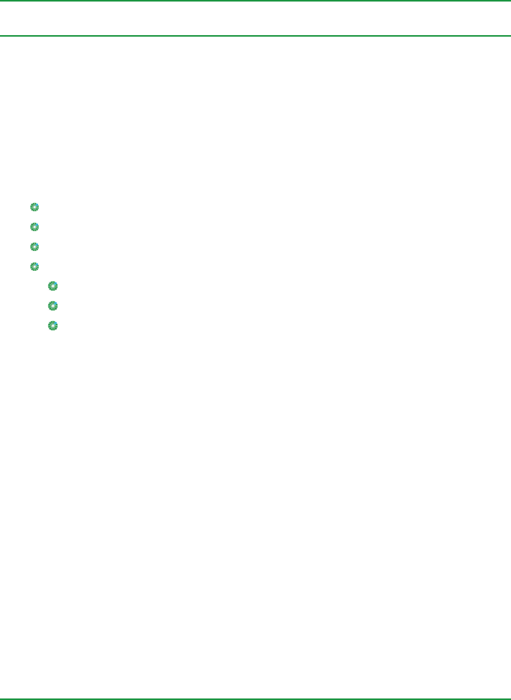
I. Battery compartment.
II. Analog input ports (4-20 mA / 0-10 V).
III. 6 X Discrete input ports.
IV. 3 X Wire 18 V DC Latch output ports.
V. Galcon RTU card as IO card.
VI. Radio INT adaptor card.
VII. Green/Red LED.
VIII. Registration button.
IX. Jumper and circuit diagram.
Figure 1: Galcon 8489 RTU Features
G2W4 and G2W8 Field Unit Features
The G2W 4 and G2W 8 Field Units have the flowing input and output ports:
4/8 x 18 V wire DC Latch output ports.
6 x Discrete input ports.
3 x Analog 4 - 20 mA / 0 - 10 V input ports.
The analog input ports can operate at a voltage range of 0-10 V or a current range of 4-20 mA. To define
the operation setting for each input port, move the jumper (Item IX in Figure 2) according to the jumper
diagram (Item VII in Figure 2) on the circuit board.
I. Battery compartment.
II. 3 x Analog inputs 4-20 ma/0-10 V.
III. 6 x Discrete inputs.
IV. Green/Red LED.
V. 4/8 x 18 V DC Latch outputs (depending
on unit type).
VI. Reset button.
VII. Diagram.
VIII. Registration button.
IX. Jumpers.
Figure 2: G2W 4 / G2W 8 Features
G2W – Gal 2 Way – Installation and Operation Guide
11
Field Units Power Supply
The field units are powered by four 1.5V D-size alkaline batteries, which are inserted into the battery
compartment. The field units can alternatively be powered by an external solar panel and charged
batteries or an internal battery. Contact Galcon to request these alternative components.
Note: Galcon RTU field units do not supply power to the connected sensors. When
connecting sensors to the analog inputs or when transmitting data to the digital inputs you
must supply an external source of power for them.
Field Units Connection
The field units can be connected to two antenna types in various combinations in order to achieve
variant communication transmission strengths. Connect each field unit to its antenna(s) with RF cables.
Do not bend the cables below a radius of 30 cm. Always keep a 60 cm distance between any two
antennas.
The various combinations below are listed according to increasing communication transmission strength:
Single 916-CW-HW antenna.
Two 916-CW-HW antennas.
916-CW-HW antenna & FG9023 antenna.
Two FG9023 antennas.
Repeater (Relay)
The repeater unit is used when the communication between a field unit and the concentrator is weak, or
when the field units are installed in locations where obstacles interfere with radio communication
between the field units and the concentrator.
The repeater is designed for installation in the field without the need for an external power source. For
this purpose, it includes both a solar panel and charged batteries.
Repeater Connections
Connect the repeater unit to two FG9023 antennas with RF cables. Do not bend the cables below a
radius of 30 cm. Always keep 60 cm distances between antennas.
Concentrator
The concentrator acts as the system manager. The concentrator transmits, via radio communication, the
commands to all the field units, and returns the various inputs of the field units to the
controller. The concentrator is connected to RF antennas and cables. The concentrator is equipped with
a backup battery which lasts for at least 24 hours.
G2W – Gal 2 Way – Installation and Operation Guide
12
The concentrator can be installed in one of two ways:
Installed close to the controller, at a distance of not more than 10 meters, using direct
communication (RS-232).
Installed at a distance of not more than 30 meters, using an RS-485 adaptor.
The concentrator is intended for outdoor use, operating at an ambient temperature range of -10o C to
+50o C, and at a maximum relative humidity up to 100%. The Ingress Protection of concentrator is IP54.
Concentrator Connections
Connect the concentrator to two FG9023 antennas with RF cables. Do not bend the cables below a radius
of 30 cm. Always keep 60 cm distances between antennas.
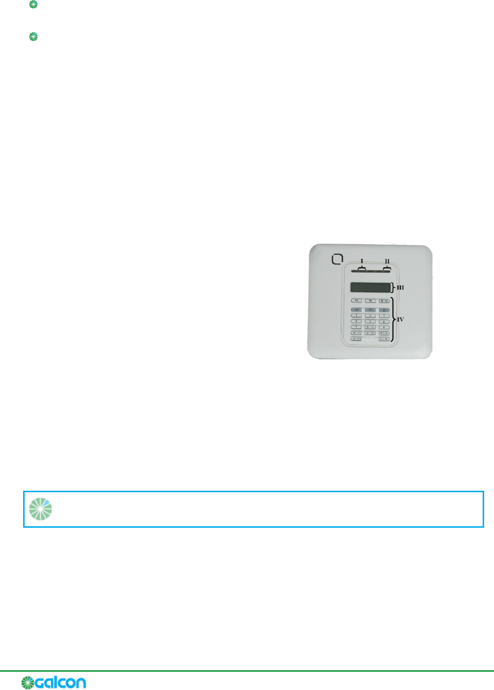
Concentrator Main Features
Figure 3: Concentrator Main Features
I. Green Led – Indicates a connection to a power
supply.
II. Orange Led – Indicates a malfunction, or that
the backup battery is in use.
III. Display screen.
IV. Programming buttons. (Refer to Concentrator
Programming Buttons on page 15 for detailed
information.)
Radio INT Adaptor Card (AC0117)
The I/O adaptor card (AC0117), known as the Radio INT card, enables the controller to perform
communication between the controller and the concentrator.
Note: The card does not supply power to the concentrator.
G2W – Gal 2 Way – Installation and Operation Guide
13
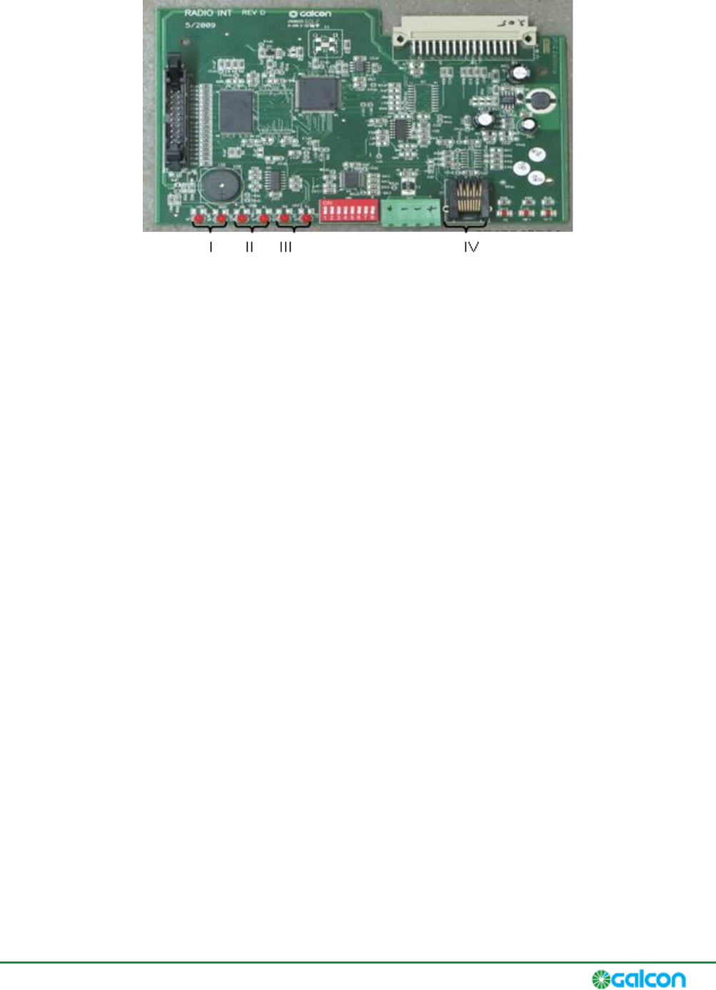
Radio INT Adaptor Card Main Features
Figure 4: Radio INT Card Components
I. LED indicators for normal card operation.
II. LED indicators for communication with the CPU.
III. LED indicators for communication with the concentrator.
IV. Communication indicator connector to the concentrator.
3 Registering System Components
All the field units and repeaters in the system need to be registered in the concentrator. This registration
process is performed on the concentrator; there is no need for any registration process on the controller.
Connecting or disconnecting the controller will not affect the registration process.
Notes:
It is recommended to position all the field units and repeaters near the concentrator
while performing registration. This maximizes the communication strength between the
units and facilitates successful registration.
Upon performing registration, each field unit and repeater unit downloads its default
configuration settings from the default values defined in the concentrator. You may
want to modify these default settings in the concentrator before performing
registration. For more information, refer to Configuring Field Units and Repeaters on
page 31.
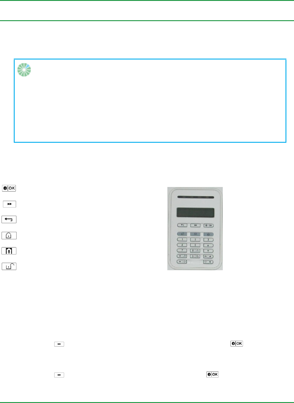
Concentrator Programming Buttons
Confirmation.
Figure 5: Concentrator Buttons
Browse forward in menus.
Browse backward in menus.
Go back to main menu, or Exit.
Go back to previous menu.
Off.
Registering Field Units
1. On the concentrator, perform the following:
a. Press until is displayed on the screen, and press to select it.
b. Enter technician code 9999. The concentrator emits four beeps and requests confirmation. Do
not change the technician code.
c. Press until DEVICES is displayed on the screen, and press to select it.
G2W – Gal 2 Way – Installation and Operation Guide
16
d. Press until is displayed on the screen, and press to select it. The
message ENROLL NOW or ENTER ID XX-XXXX flashes on the screen.
2. On the field unit you are registering, hold down the registration button (see Figure 1 or Figure 2)
until the red LED turns on. Release the registration button. The station number and the Galileo
number flash on the screen (for example: SO1: Galcon RTU, GALILEO NUM: 05).
3. On the concentrator, press to confirm registration. The concentrator emits four beeps and the
enrollment message stops flashing.
4. To register additional units, perform the following on the concentrator:
a. Press . The message is displayed on the screen.
b. Press . The message ENROLL NOW or ENTER ID XX-XXXX flashes on the screen.
c. Repeat steps 1 through 3 to register an additional field unit.
Repeat these sub-steps until you have registered all the field units.
5. After you have registered all the field units, press to end the registration process and exit to the
main menu.
6. Press to confirm the registration. The message DEV UPDATING is displayed on the screen.
The concentrator emits four beeps and returns to the main display screen.
7. Perform a communications diagnostics test on the registered field units. Refer to Performing
Communications Diagnostics Tests on page 25.
Registering Repeaters
1. On the concentrator, perform the following:
a. Press until is displayed on the screen, and press to select it.
b. Enter technician code 9999. The concentrator emits four beeps and requests confirmation. Do
not change the technician code.
c. Press until DEVICES is displayed on the screen, and press to select it.
d. Press until is displayed on the screen, and press to select it. The
message - flashes on the screen.
2. On the repeater unit you are registering, hold down the registration button (see Figure 1 or Figure 2)
until the red LED turns on. Release the registration button. The station number and the Galileo
number flash on the SO1: Gal2Way 2 GALILEO NUM: 09
3. On the concentrator, press to confirm registration. The concentrator emits four beeps and the
enrollment message stops flashing.
4. To register additional units, perform the following on the concentrator:
a. Press . The message is displayed on the screen.
b. Press . The message - flashes on the screen.
G2W – Gal 2 Way – Installation and Operation Guide
17
c. Repeat steps 1 through 3 to register an additional repeater unit.
Repeat these sub-steps until you have registered all the repeater units.
5. After you have registered all the repeater units, press to end the registration process and exit to
the main menu.
6. Press to confirm the registration. The message is displayed on the screen.
The concentrator emits four beeps and returns to the main display screen.
7. Perform a communications diagnostics test on the registered repeaters. Refer to Performing
Communications Diagnostics Tests on page 25.
Viewing the List of Registered Field Units and Repeaters
You can optionally view the list of field units and repeaters which are registered to the concentrator.
To view the list of registered field units and repeaters:
1. Press until is displayed on the screen, and press to select it.
2. Enter technician code 9999. The concentrator emits four beeps and requests confirmation. Do not
change the technician code.
3. Press until DEVICES is displayed on the screen, and press to select it. The MODIFY
DEVICES option is displayed.
4. Press .
5. Press to browse through the list of field unit and repeater types. When the type you want to
view is displayed, press to select it.
6. Press to browse through the list of registered field units or repeaters of the type you selected.
Optionally, press for a displayed field unit or repeater to view detailed configuration
information about it, including the station number and Galileo controller ID number.
7. Press to exit to the main menu, and press to confirm. The message is
displayed on the screen. The concentrator emits four beeps and returns to the main display screen.
4 Installing the G2W System
Pre-Installation Planning
Before installing the components of the Gal2Way system, make sure to examine the installation
environment to determine the best locations for installation.
You must make sure to install components above obstructions which may interfere with the RF
transmissions between components. All components must be installed such that there is line-of-sight
between all component antennas.
Verify that there is a direct line-of-sight between the location of the unit and the location
of the .
Make sure that the distance between the field unit and the concentrator does not exceed 2 km.
Field unit antennas are to be installed on poles which are not less than 2 m high. Verify that there are
no obstructions which are more than 2 m high between the field unit and the concentrator.
If there is a significant obstruction between a field unit and the concentrator and no better location
can be found, you may be able to install a repeater (relay) to serve as an intermediary.
For the repeater, you should find a location which has line-of-sight, without significant obstructions,
and is within 2 km of both the concentrator and the field unit.
Notes:
In order to achieve the maximum results with the fewest repeaters, place the repeaters
in locations which support the maximum number of units. The system can support up to
four repeaters.
The system does not support chains of repeaters.
Installing the Concentrator
The appropriate location for installing the concentrator is determined according to the communication
type used:
When direct communication (RS-232) is used, the installation should be next to the controller, at a
distance of up to 10 m.
When using an RS-485 adaptor, the installation can be further away, at a distance of up to 30 m.
The concentrator should be positioned so that the communications and voltage cable will reach the
controller.
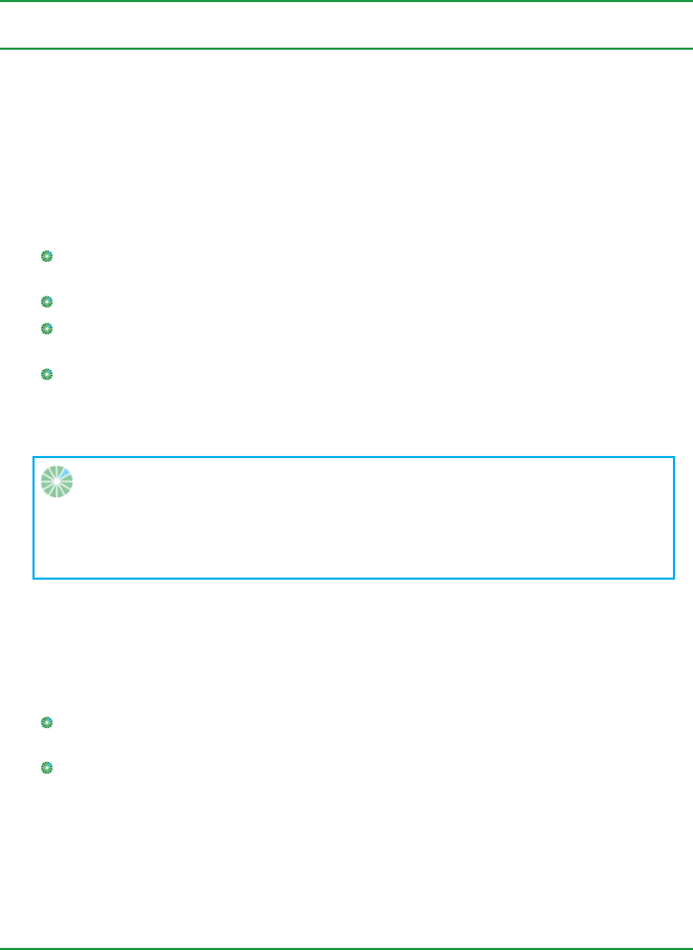
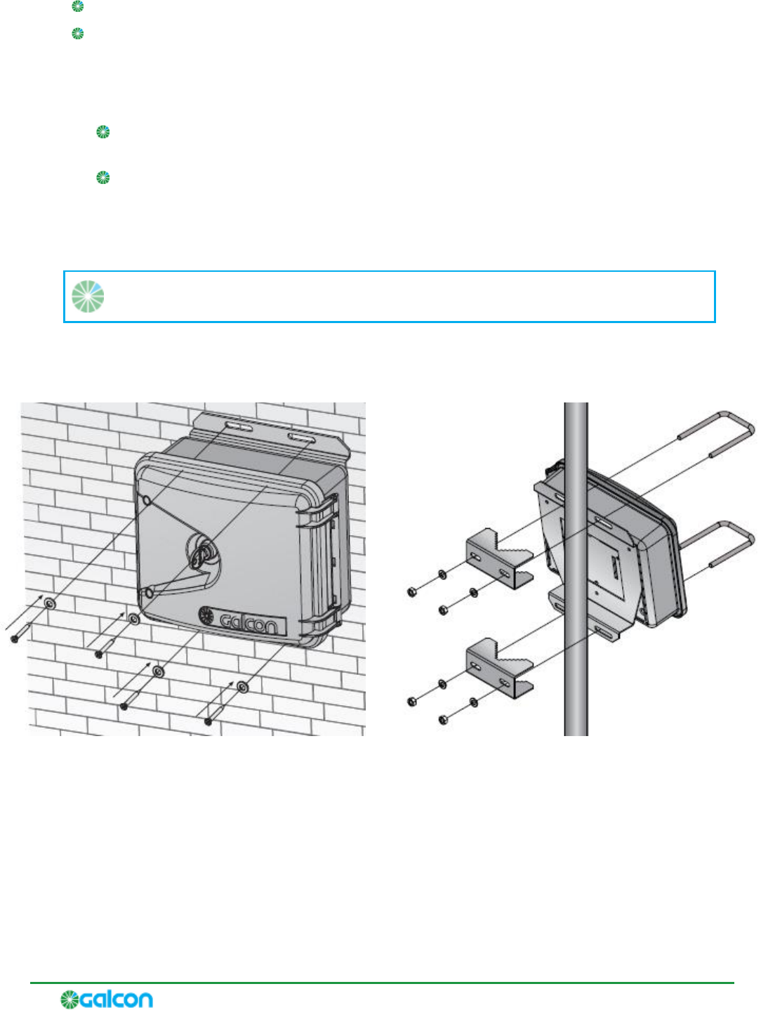
Affix the concentrator to the wall by inserting screws through the holes in the aluminum plate at the
back of the box.
G2W – Gal 2 Way – Installation and Operation Guide
20
Figure 6: Installing the Concentrator
Connecting the Concentrator to an External Power Supply
The process of connecting the concentrator to a power source depends on whether you are installing a
DC or an AC unit:
DC-operated Concentrator Connect a power supply of 12V DC to the correspondingly labeled
connector.
AC-operated Concentrator Connect the supplied power supply unit.
Note:
power supply of 9V 700mA AC
- The concentrator includes an internal backup battery which lasts for at least 24
hours.
Note:
The concentrator should be located within shelter for direct, initial
Protection from effects of the weather
G2W – Gal 2 Way – Installation and Operation Guide
21
Connecting the Concentrator to the Controller via RS-232 Connections
To connect the concentrator to the controller:
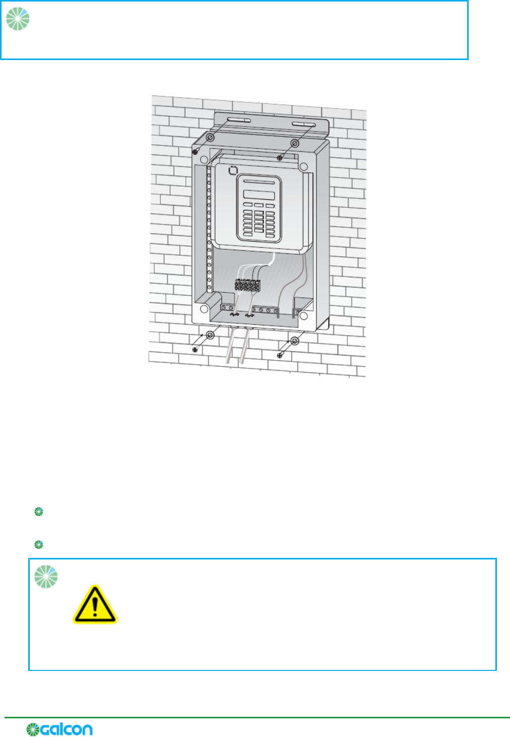
1. Connect one end of the eight-wire communication cable to the Radio INT adaptor card, located in
the controller. Connect other end to the Galcon Galcel (AI0617) connector.
2. Connect the Galcel connector to the communication adaptor.
Figure 7: Galcel-to-Adaptor Connection
The communication adaptor is used to convert outgoing RS-232 signals from the Radio INT adaptor
card into RS-485 signals; this enables the transmission of the signals to the concentrator even at a
distance from the controller (up to 30 m).
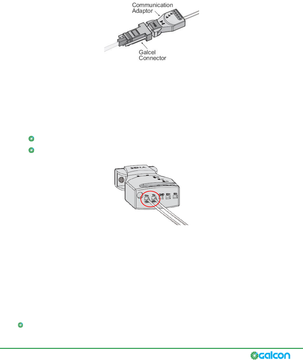
3. Connect the double-wire communication cable from the concentrator to the communication
adaptor:
Connect the brown wire to input TX+ in the communication adaptor.
Connect the blue wire to input TX- in the communication adaptor.
Figure 8: Double-Wire Cable Connections to Communication Adaptor
Installing Field Units
After planning appropriate locations for field units and registering them, you can install the field units.
Field units are designed to fully withstand sun and rainy weather, so no shelter is required when
installing field units.
It is recommended that you install field units according to the following parameters:
Position the unit at a height which enables easy access to the unit when necessary.
G2W – Gal 2 Way – Installation and Operation Guide
22
Position the unit so that its cable inputs are positioned downward.
Position the antenna at least 2 meters above the ground.
To install a field unit:
1. Install the field unit in one of the following ways:
Affix the unit to any vertical surface by means of screws, inserted through the holes in the
aluminum plate at the back of the unit box (Figure 9).
Affix the unit to a metal pipe of 1 ¼" or 1 ½" diameter using the supplied hanging accessories. As
an example, the unit can be affixed to the lower part of the pole to which the antennas are
attached (Figure 10).
2. Connect the antenna cable to the cable connector at the bottom of the unit.
Note: Do not bend the cables below a radius of 30 cm.
3. Gently gather and affix any extra cable length to the wall or pole on which you installed the field
unit.
Figure 9: Affixing the Unit to a Wall
Figure 10: Affixing the Unit to a Pole
Installing Repeaters
solar panel must be positioned southward in the northern
hemisphere, and northward in the southern hemisphere.

G2W – Gal 2 Way – Installation and Operation Guide
23
To install the repeater:
1. Install the repeater in one of the following ways:
Affix to any vertical surface by inserting screws through the holes in the aluminum plate at the
back of the unit box.
Affix on a metal pipe of 1 ¼" or 1 ½" diameter using the supplied hanging accessories. As an
example, the unit can be affixed to the lower part of the pole to which the antennas are
attached.
2. Connect the antenna cable to the cable connector at the bottom of the repeater.
Note: Do not bend the cables below a radius of 30 cm.
3. Gently gather and affix any extra cable length to the wall or pole on which you installed the repeater.
5 Performing Communications Diagnostics Tests
The communications diagnostics test is used to test the communication strength between the
concentrator and each registered field unit or repeater. You can perform this test for all units
simultaneously (from the concentrator), or for one unit at a time (either from the concentrator or from
each unit itself).
Performing the Communications Diagnostics Test for all Field Units and
Repeaters Simultaneously from the Concentrator
To perform the communications diagnostics test for all field units simultaneously from the
concentrator:
1. Press until is displayed on the screen, and press to select it.
2. Enter technician code 9999. The concentrator emits four beeps and requests confirmation. Do not
change the technician code.
3. Press until DIAGNOSTICS is displayed on the screen, and press to select it. The
WL DEVICES option is displayed on the screen.
4. Press . The TEST ALL DEVICES option is displayed on the screen.
5. Press .
The communication diagnostics test between the concentrator and all registered field units is
performed. When the test is finished, the screen displays
6. Press .
7. Press to browse among the units. The test results are displayed beside the ID number of each
unit in the list. The test results include the following sets of data:
Communications strength during the last 24 hours.
Current communications strength.
The possible values of communication strength are as follows:
STRONG
GOOD
POOR
NOT TST
8. Press to exit to the main menu, and press to confirm. The message is
displayed on the screen. The concentrator emits four beeps and returns to the main display screen.
G2W – Gal 2 Way – Installation and Operation Guide
26
Performing the Communications Diagnostics Test for One Field Unit or
Repeater from the Concentrator
To perform the communications diagnostics test for one field unit from the concentrator:
1. Press until is displayed on the screen, and press to select it.
2. Enter technician code 9999. The concentrator emits four beeps and requests confirmation. Do not
change the technician code.
3. Press until TEST ONE DEVICE is displayed on the screen, and press to select it.
4. Press to browse through the list of field unit and repeater types. When the type you want to
view is displayed, press to select it.
5. Press to browse through the list of registered field units or repeaters of the type you selected
until the field unit you want to test is displayed on the screen.
6. Press . The diagnostics test is performed for that field unit.
While the test is performed, the message TESTING is displayed on the screen, as well as the station
number (for example, TESTING S01 001). When the test is finished, the screen displays the test
results, including each of the following sets of data:
Communications strength during the last 24 hours.
Current communications strength.
The possible values of communication strength are as follows:
STRONG
GOOD
POOR
NOT TST
7. Press to exit to the main menu, and press to confirm. The message is
displayed on the screen. The concentrator emits four beeps and returns to the main display screen.
G2W – Gal 2 Way – Installation and Operation Guide
27
Performing the Communications Diagnostics Test from One Field Unit or
Repeater
Note: Performing communications diagnostic tests from a field unit or repeater
requires that you open the field unit and access the registration button on its circuit
board. Refer to System Components on page 9.
G2W4 and G2W8 field units support an alternative method which can be performed
Performing the Communications
Diagnostics Test from One G2W4 or G2W8 Field Unit on page 27.
To perform the communications diagnostics test from one field unit:
Press the registration button on the field unit or repeater. The LED blinks three times while the
test is performed, and then the LED blinks three more times to display the test results:
Three red blinks means LOW communication strength, or no communication strength at all.
Three orange blinks means MEDIUM communication strength.
Three green blinks means STRONG communication strength.
Performing the Communications Diagnostics Test from One G2W4 or
G2W8 Field Unit
G2W4 and G2W8 field units enable you to perform the diagnostics test usin
without needing to open the field unit and access the circuit board.
To perform the communications diagnostics test from one G2W4 or G2W8 field unit:
1. Press until the icon and the message rSSI are displayed on the screen.
2. Press . The icon flashes and the unit performs the communications diagnostics test.
Note: If the unit cannot perform the test, the icon continues to flash until the screen
shuts down. You can press any button to reactivate the screen.
When the test is complete, the screen displays the results:
0 No communications strength at all.
1 LOW communications strength.
5 MEDIUM communications strength.
10 STRONG communications strength.
G2W – Gal 2 Way – Installation and Operation Guide
28
Viewing Communications Strength from the Controller
When enabled, the controller displays the communication strength between the concentrator and field
The communication strength value displayed by the controller ranges between 0 and 255, with 255 being
the strongest value. The minimum required communication strength is 170.
If no repeaters are in use in the system, the value displayed indicates the communication strength
between the unit and the concentrator.
When a repeater is in use in the system, the value displayed indicates the communication strength
between the field unit and the repeater.
This feature is not enabled by default.
Enabling Communications Strength Display in the Controller
In order to view the communications strength value, you must first define the fourth analog input for
each field unit. This input transmits the communications strength value to the controller.
To enable communications strength display in the controller:
1. Launch the Galileo Client software.
2. Click Setup > Connections>Inputs> Analog sensors. A window appears.
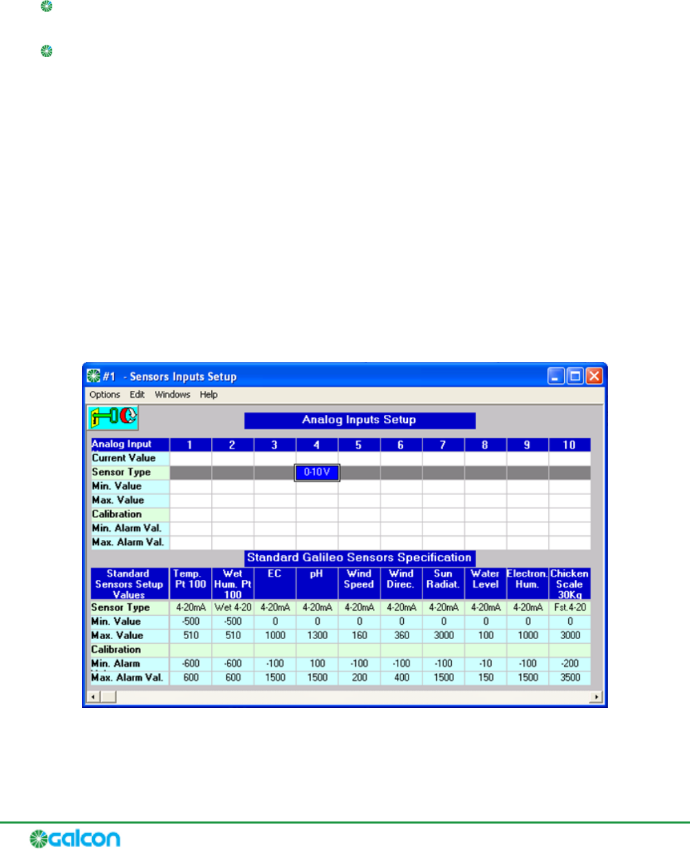
3. At the lower part of the window, click Sensor Definition. The Analog Inputs Setup window appears.
Figure 11: Analog Inputs Setup Window
4. Click the key symbol.

G2W – Gal 2 Way – Installation and Operation Guide
29
5. For the fourth input of each field unit, define the following input settings:
In the Sensor Type row, enter 0-10 V.
In the Min. Value row, enter 0.
In the Max. Value row, enter 255.
6 Configuring Field Units and Repeaters
All field units and repeater units have various configurable parameters. When registering a unit with the
concentrator, the unit receives its default setting definitions from those defined for the concentrator.
You can redefine the concentrator settings before registration to automatically upload the modified
settings to the units upon registration. In addition, after registration, you can modify the settings for any
unit individually.
The configuration options for the concentrator, all field units, and all repeaters are as follows:
Sampling Period Frequency with which the Radio INT adaptor card samples the field unit.
Default value: 1 second.
Reporting Period Frequency with which a field unit sends status reports to the concentrator.
Default value: 1 minute.
Charge Time Maximum waiting time to charge the capacitor before operating the valve.
Default value: 30 seconds.
Output setting Not relevant. Default value: ALL OFF.
Digital Input 0 -7 For each input, you can define the number of pulses, with which a field unit sends
status reports to the concentrator. Default value: 1 pulse.
Modifying the Default Field Unit Configuration Settings in the
Concentrator
To change the default field unit configuration settings in the concentrator:
1. Press until is displayed on the screen, and press to select it.
2. Enter technician code 9999. The concentrator emits four beeps and requests confirmation. Do not
change the technician code.
3. Press until DEVICES is displayed on the screen, and press to select it.
4. Press until DEFINE DEFAULTS is displayed on the screen, and press to select it.
5. Press to browse through the list of configuration parameters. When the parameter you want to
modify is displayed, press .
6. Press to browse through the various settings options for the selected parameter and click
when the desired value is displayed. The concentrator emits four beeps and displays the message
SAVING while saving the modified parameter setting.
After saving the modifications, the screen returns to the selected parameter.
7. Optionally, browse to other configuration parameters and modify them as desired.
G2W – Gal 2 Way – Installation and Operation Guide
32
8. Press to exit to the main menu, and press to confirm. The message is
displayed on the screen. The concentrator emits four beeps and returns to the main display screen.
Modifying the Configuration Settings for Individual Field Units from the
Concentrator
To modify the configuration settings for individual field units from the concentrator:
1. Press until is displayed on the screen, and press to select it.
2. Enter technician code 9999. The concentrator emits four beeps and requests confirmation. Do not
change the technician code.
3. Press until DEVICES is displayed on the screen, and press to select it. The MODIFY
DEVICES option is displayed.
4. Press .
5. Press to browse through the list of field unit and repeater types. When the type you want to
view is displayed, press to select it.
6. Press to browse through the list of registered field units or repeaters of the type you selected
until the field unit you want to modify is displayed on the screen.
7. Press .
and the DEV SETTINGS option.
8. Press .
9. Press to browse through the list of configuration parameters. When the parameter you want to
modify is displayed, press .
10. Press to cycle through the various settings options for the selected parameter and click
when the desired value is displayed. The concentrator emits four beeps and displays the message
SAVING while saving the modified parameter setting.
After saving the modifications, the screen returns to the selected parameter.
11. Optionally, browse to other configuration parameters and modify them as desired.
12. Press to exit to the main menu, and press to confirm. The message is
displayed on the screen. The concentrator emits four beeps and returns to the main display screen.
Deleting Field Units or Repeaters from the Concentrator Registry
To delete field units or repeaters from the concentrator registry:
1. Press until is displayed on the screen, and press to select it.
G2W – Gal 2 Way – Installation and Operation Guide
33
2. Enter technician code 9999. The concentrator emits four beeps and requests confirmation. Do not
change the technician code.
3. Press until DEVICES is displayed on the screen, and press to select it.
4. Press until DELETE DEVICES is displayed on the screen, and press to select it.
5. Press to browse through the list of field unit and repeater types. When the type you want to
view is displayed, press to select it.
6. Press to browse through the list of registered field units or repeaters of the type you selected
until the field unit you want to modify is displayed on the screen.
7. Press . The message <OFF> to delete is displayed.
8. Press to confirm the deletion. The concentrator emits four beeps and the unit is removed from
the list. The display returns to the list of field unit and repeater types.
9. Optionally, repeat steps 6 through 8 to delete additional field units or repeaters.
Note: After deleting the last field unit or repeater in the registry, the message NO EXISTING
DEV is displayed, indicating that there are no devices in the registry to delete.
10. Press to exit to the main menu, and press to confirm. The message is
displayed on the screen. The concentrator emits four beeps and returns to the main display screen.
7 Operating Gal2Way 4 and Gal2Way 8 Field Units
In addition to the Galcon RTU field unit type, the G2W system supports the following second-generation
field unit types: Gal2Way 4 and Gal2Way 8. These field units have four or eight output connectors
respectively.
You can perform various tasks directly from the Gal2Way 4 and Gal2Way 8 units.
Note: The Gal2Way 4 and Gal2Way 8 field units are designed so that their screens are
turned off by default, as an energy saving feature. Before performing any of the following
procedures, first press any button on the field unit to activate the screen and view the main
display.
When connecting the Gal2Way 4 and Gal2Way 8 Field Units to a power supply, the units signal to all
their output ports to close. Similarly, when resetting Gal2Way 4 and Gal2Way 8 Field Units, the units
signal to all their output ports to close while turning back on.
Viewing the Communication Status and Serial Number
To view the communication strength of a G2W4 or G2W8 field unit, perform the procedure Performing
the Communications Diagnostics Test from One G2W4 or G2W8 Field Unit on page 27.
Viewing the Galileo ID Number
To view the Galileo ID number of the field unit:
1. Press until the icon and the message rSSI are displayed on the screen.
2. Press . Sn is displayed on the screen.
3. Press . The Galileo ID number of the field unit is displayed.
Viewing the Battery Status
Press repeatedly until the icon is displayed on the screen. After a few seconds the screen
displays the voltage of the connected battery.

G2W – Gal 2 Way – Installation and Operation Guide
36
Testing Output Ports
In order to test the ports, perform the following test to each port.
To test output ports:
1. Press . The main screen is displayed.
2. Press to move through the list of output ports.
3. When the desired output port is displayed, press to activate it. The screen displays the number
of the selected output port and indicates that it is now on. The output port opens for one minute,
after which it closes automatically.
If you want to manually close the output port before the full minute elapses, press to close the
output port.
Upon closing, the screen displays the number of the selected output port and indicates that it is
off.
Verifying the Connection to Discrete Input Devices
G2W4 and G2W8 field units have six discrete input ports.
When a device is connected to one of these ports, the icon is displayed next to the word
and above a number between 1 and 6, corresponding to each of the six ports. Look for these indicators
to verify connection to discrete input devices.
Viewing the Analog Input Device Signal Levels
G2W4 and G2W8 field units have three analog input ports which can be connected to devices.
The analog input ports can operate at a voltage range of 0-10 V, or a current range of 4-20 mA. To define
the operation setting for each input port, refer to G2W4 and G2W8 Field Unit Features on page 10.
To view the voltage and current of the analog input device signals:
1. Press until the number 1 flashes on the screen next to the word Analog and the letter V
(representing Volts) appears on the screen. Wait a few seconds. The screen displays the first analog
2. Press to change the display from voltage to current. The letters mA are displayed on the screen.
3. Press to browse through the various connected analog input devices, displaying the voltage or
current values for each one.
8 Converting the Galileo Controller to the G2W
System
Converting the Galileo controller to the G2W system involves installing one or two Radio INT adaptor
cards, and configuring the Galileo controller to enable recognition of radio field units and repeaters. This
is achieved by defining the number of radio units will be added to the system, and assigning adaptor card
slots to them.
Installing Radio INT Adaptor Cards
Note: Each Radio INT adaptor card provides 64 ports in the Galileo controller for radio field
units. Every two field unit output ports require one port on the controller; for example, a
field unit with four output ports requires 2 ports in the controller, etc. If more controller
ports are required for radio field units, you must install additional adaptor cards (each with a
corresponding concentrator) in the Galileo controller.
To install a Radio INT adaptor card:
1. Verify that the controller power supply is disconnected.
2. Insert the Radio INT adaptor card (AC0117) to the corresponding slot in the Galileo controller.
3. Reconnect the controller power supply.
Defining the Number of Units in the System
After installing the Radio INT adaptor card, you must define the number of field units (whether cable
units or radio units) which will be registered in the system.
Note: It is recommended that you define the exact number of units you plan to currently
use in the system. If you define a larger number, the controller will waste resources scanning
for units which do not exist. If you need to add additional units at a later time, you can
change the defined number of units.
To define the number of units in the system:
1. Launch the Galileo Client software.
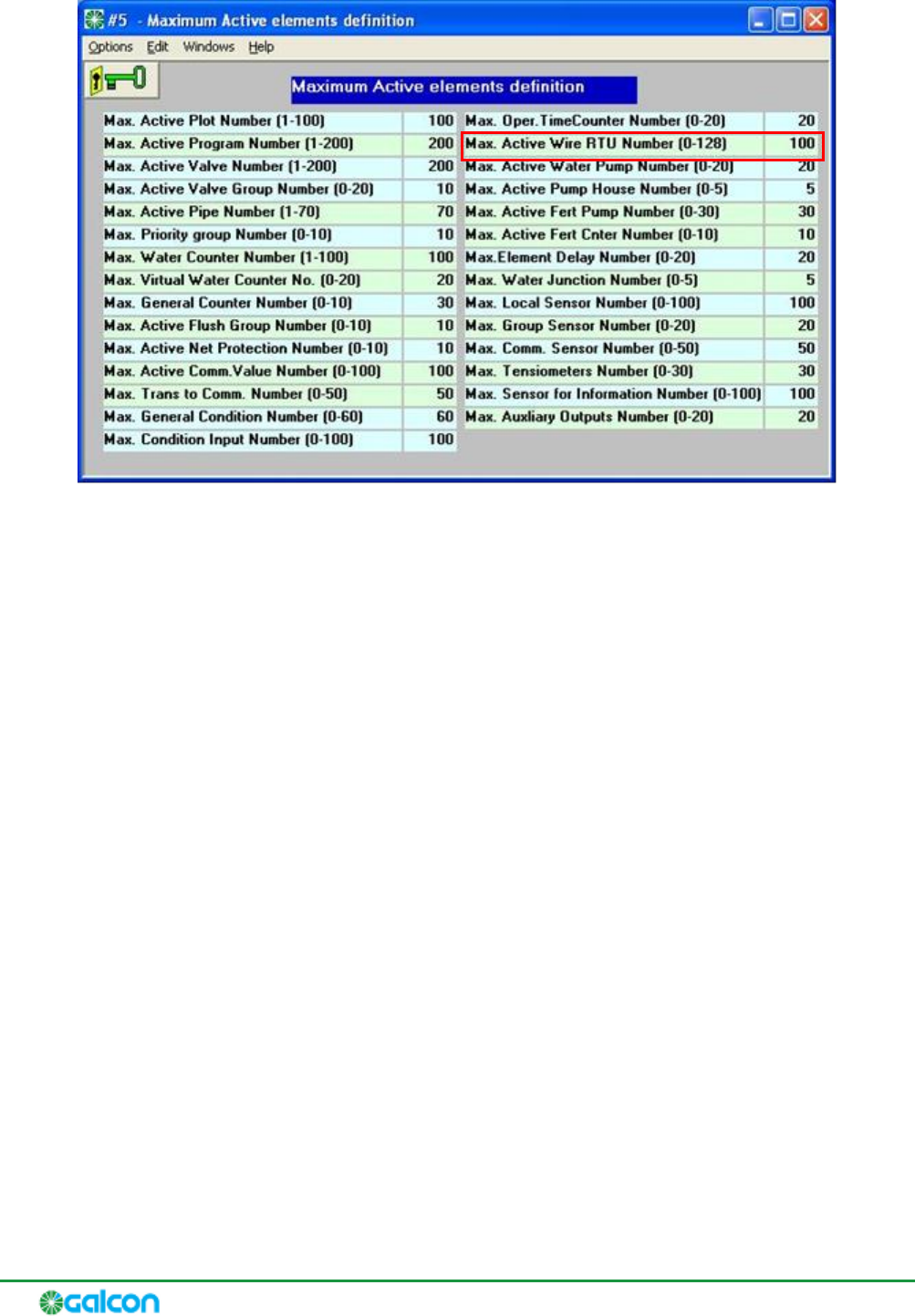
2. Click Setup > Controller setup > Maximum elements definition. The Maximum Active elements
definition window appears.
G2W – Gal 2 Way – Installation and Operation Guide
38
Figure 12: Maximum Active Elements Definition Window
3. Click the key symbol.
4. In the Max. Active Wire RTU Number (0-128) row, enter the total number of field units and
repeaters, both cable and radio, that are to be registered in the system.
5. Click the key symbol again for confirm the change.
Assigning Adaptor Card Slots for Field Units in the System
To assign adaptor card slots for field units in the system:
1. Launch the Galileo Client software.
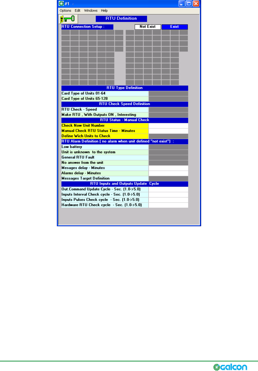
2. Click Service > RTU state > Defining RRTU. The RTU Definition window is appears.
G2W – Gal 2 Way – Installation and Operation Guide
39
Figure 13: RTU Definition Window
3. Click the key symbol.
4. In the RTU Connection Setup area, select ports for allotment to field units according to the
calculation that each field unit requires one controller port for every two field unit output ports.
For example, three field units which have four output ports each might require the selection of 1-2,
3-4, and 5-6.
5. In the Card Type of Units 01-64 row, select Radio Two Directions. If a second Radio INT adaptor card
is installed, select Radio Two Directions in the Card Type of Units 65-128 row as well.
6. Under Defining alarms of RRTU, define the timing for alarms and notices to be sent by the controller
when faults or errors occur in the radio field units.
7. Click the key symbol again for confirm the change.
A Safety Instructions for Installing Antennas
Do not climb on the antenna pole. In order to lower/raise the antenna for maintenance operations,
remove one of the anchoring screws and lower the antenna and axis to the floor.
Do not set up antennas near high voltage lines.
Make sure that the base of each antenna is properly positioned and affixed to the concrete floor.
Make sure that the antenna pole is properly connected and secured to the base.
When the antenna pole is higher than 6 meters, the antenna pole must be secured by 3 additional
metal cables from the top of the pole to the ground. Mark the cables according to the applicable
safety regulations.
Warning! Only personnel with the necessary official qualifications, including passing the
official Ministry of Labor climbing course, may climb antenna poles. While doing so, all such
personnel must follow all of the applicable safety regulations.
The antenna(s) used for this transmitter must be installed to provide a separation distance
of at least 1 m from all persons
FCC Compliance Statement
This device has been tested and found to comply with the limits for a Class B digital device, pursuant to Part 15 of
the FCC Rules. These limits are designed to provide reasonable protection against harmful interference in residential
installations. This equipment generates uses and can radiate radio frequency energy and, if not installed and used in
accordance with the instructions, may cause harmful interference to radio and television reception.
However, there is no guarantee that interference will not occur in a particular installation. If this device does cause
such interference, which can be verified by turning the device off and on, the user is encouraged to eliminate the
interference by one or more of the following measures:
– Re-orient or re-locate the receiving antenna.
– Increase the distance between the device and the receiver.
– Connect the device to an outlet on a circuit different from the one that supplies power to the receiver.
– Consult the dealer or an experienced radio/TV technician.
WARNING! Changes or modifications to this unit not expressly approved by the party responsible for compliance
could void the user’s authority to operate the equipment.

Limited Warranty Certificate
1. Galcon shall, for a limited period of 12 months from the retail purchase date of the original (first)
subject to the provisions and limitations of this Limited Warranty Certificate.
2.
signed contract with Galcon (or any of its authorized dealers) together with a valid purchase receipt.
Failure to produce the said documentation will result in the request for warranty being null and void.
3. Galcon warrants to the Customer that the Product shall materially conform to the description in
free from defects in material and workmanship. Accordingly,
discretion the replacement of the Product or any part\s according to the terms of this Warranty,
and no other remedy shall be available. Therefore, if - within the Warranty Period - the Product is
proven to be defective by reason of faulty workmanship or materials by Galcon, Galcon undertakes,
with reasonable promptness, to have the defective Product (or any part/s thereof) repaired, or at
Certificate.
4.
conduct (by act or omission) not by Galcon, including any misuse/abuse of any Product (or part/s
instructions; (ii) other systems/components/devices/technologies and/or the integration/interface
thereof with any Product; (iii) any part/component which has been included/installed in any Product
change/repair/interference of/with any Product (including any use/handling of, and/or
interference/dealing with, any code of any software included/used in the Product) other than by
Galcon; (v) any data/information/content which has been inserted/included in a Product; (vi)
malfunction or damage resulting from accidents, which occur during transit and/or handling, and/or
malfunction or damage due to fire, earthquake, flood, lightning and/or any other external disaster;
asonable
control, or to any Product installed, repaired, adjusted, rebuilt, modified, changed or converted by
any person (including the Customer) other than Galcon;
5. is
obligation to the Galcon (or its authorized dealer, as relevant).
6. Galcon does not give any warranty or guarantee whatsoever in respect of any Product (or any part/s
thereof) which has not been manufactured and distributed by the Galcon and which has not been
purchased from the Galcon or any of its authorized dealers, whether such products are branded with

G2W – Gal 2 Way – Installation and Operation Guide
43
any trademarks similar to any trademark belonging to or used by Galcon.
7. After replacement or repair of the Product, the Warranty for the new or repaired Product shall be
valid only for the non-expired period of the original Warranty Period. Any defective Products or
8. Galcon reserves the right to charge the Customer if any warranty service is requested and carried out
but no fault is found in t
9. Notwithstanding anything to the contrary, Galcon shall not be responsible and/or liable, under any
circumstances and in any way, for any loss, damage, costs, expenses, expenditures, responsibility
and/or liability (including of Customer and/or any third party) including (without limitation) direct
and/or indirect (including incidental and/or special and/or consequential), however arising, including
in respect of damages to or loss of property and/or equipment, loss of profit, loss of use, loss of
revenue or damages to business or reputation, whether or not based on breach of contract, tort
(including negligence), product liability or otherwise - arising from the performance or non-
performance of any aspect of the Product or any part thereof; All of the above, whether or not
Galcon and/or the Customer shall have been made aware of the possibility of such loss.
10. In any event, any liability which Galcon may have in connection with the Product and/or this
Warranty, including (without limitation) in connection with and/or resulting from the Product (or any
part thereof) and the use thereof, shall be limited to a total amount (for all damages, claims and
causes of action in the aggregate) equal to the consideration actually received by Galcon from the
Customer for the Product. The limitations shall apply whether the liability is based on contract, tort,
strict liability or any other theory.
11. This Warranty and the remedies set forth herein are exclusive and in lieu of all other warranties,
remedies and conditions, whether oral, written, statutory, express or implied. Galcon specifically
disclaims any and all statutory or implied warranties, including, without limitation, warranties of
merchantability and fitness for a particular purpose and warranties against hidden or latent defects.
12. The Customer shall be solely responsible for the selection, use, efficiency and suitability of the
Product(s).
13. The provisions of this Limited Warranty Certificate shall be interpreted and governed, solely and
exclusively, pursuant to the laws of the State of Israel, and no other law shall apply. Any and all legal
actions shall be litigated within the jurisdiction of the courts of Israel, and no other jurisdiction shall
apply.