Gallagher Group C19753U Prox Reader Mifare (Teardrop) User Manual 3E1100r16 ULcert
Gallagher Group Ltd Prox Reader Mifare (Teardrop) 3E1100r16 ULcert
Users Manual
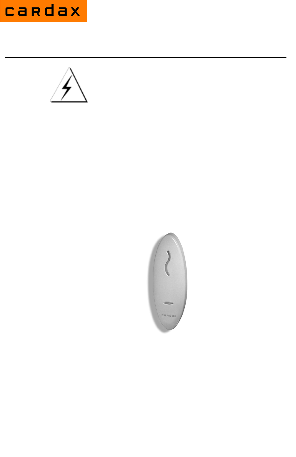
Installation Note
Part number 3E1100 R16 1
July 2010
CAUTION
This equipment contains components that can be damaged by
electrostatic discharge. Ensure both you and the equipment are
earthed before beginning any servicing.
Before you Begin
Unpack the Prox Mifare Series (Teardrop) reader and check the shipment
contains the following items:
• 1 x Prox Mifare Series (Teardrop) reader base
• 1 x Prox Mifare Series (Teardrop) reader facia
• 1 x printed circuit board (PCB) assembly
• 1 x cable assembly
• 1 x M3 Torx Post Security screw
• 4 x self tapper pozi counter sunk fixing screws (two different lengths)
WARNING: You must use the screws provided, as using other types of
screws could interfere with the electronics. (See the “Mounting” section
later for further explanation.)
Firmware
Version vMT3.07 (or later) of the Prox Mifare Series (Teardrop) reader
firmware code supports the Mifare Enhanced Security feature. This feature
provides a method of ensuring that readers reading Mifare cards are able to
prevent access through the use of replicated cards, and is optional for
customers, (i.e. customers can choose whether to use this enhanced security
and which doors to apply it to).
The Mifare Enhanced Security feature is only supported when the reader is
connected to a Cardax FT Controller 3000 or a Cardax FT GBUS Universal
Reader Interface.
Prox Mifare Series (Teardrop)

2 Part number 3E1100 R16
July 2010
Power Supply Requirements
Power for the Prox Mifare Series (Teardrop) reader is usually taken from the
incoming supply of the device to which it is connected. That is, from the:
• Cardax FT Controller 3000-4R
• Cardax FT Controller 3000
• Cardax FT GBUS Universal Reader Interface (Cardax FT GBUS URI)
The supply at the reader should be 13.6 Vdc ± 15% (between 11.5 and 15.6
volts) It is recommended that the voltage should be between 12 and 15 volts to
allow for local installation and environmental conditions, to ensure reliable
operation.
The power source for Prox Mifare Series (Teardrop) readers should only be
linear or good quality switched mode power supplies. The performance of the
reader may be affected by a low quality, noisy power supply.
Cabling
The Prox Mifare Series (Teardrop) reader uses the Cardax IV communications
system. The reader cable entry grommet is designed to accept 4 core, 0.2mm2
(24 AWG) cable. This cable has an outside diameter of 5mm (1/5 inch). A
short tail of this cable is supplied with connector fitted, with each reader.
When using a single cable to carry both power supply and data from the source
to the reader, both the power supply voltage drop and data requirements must
be considered. The cable uses two wires for data and two wires for power
supply.
Power: The conductor size should be sufficient to ensure that the voltage at the
reader terminals is not less that 12 Vdc.
Data: The capacitance between any conductors or any conductors and the
shield should not exceed a total of 24nF for the entire cable. A twisted
pair is recommended for the data circuit.
It is recommended that the distance between the control unit and the reader
should not exceed 200m (600ft).
Choosing a cable
The cable chart below lists cable sizes and the maximum length for connecting
a single Prox Mifare Series (Teardrop) reader to a Controller and power
supply.
Cable type Maximum distance *
CAT 5 ** 40m (130 ft)
4 x 0.2mm2 (4 x 24 AWG) 40m (130 ft)
4 x 0.5mm2 (4 x 20 AWG) 100m (330 ft)
4 x 1mm2 (4 x 18 AWG) 200m (660 ft)
* These distances apply to unshielded cable. If shielded cable is used, the
distances will be reduced due to the increased capacitance caused by the
shielding.
Part number 3E1100 R16 3
July 2010
** CAT 5 is not recommended for security systems as this cable has solid
copper conductors and is designed for use with RJ45 insulation displacement
connectors.
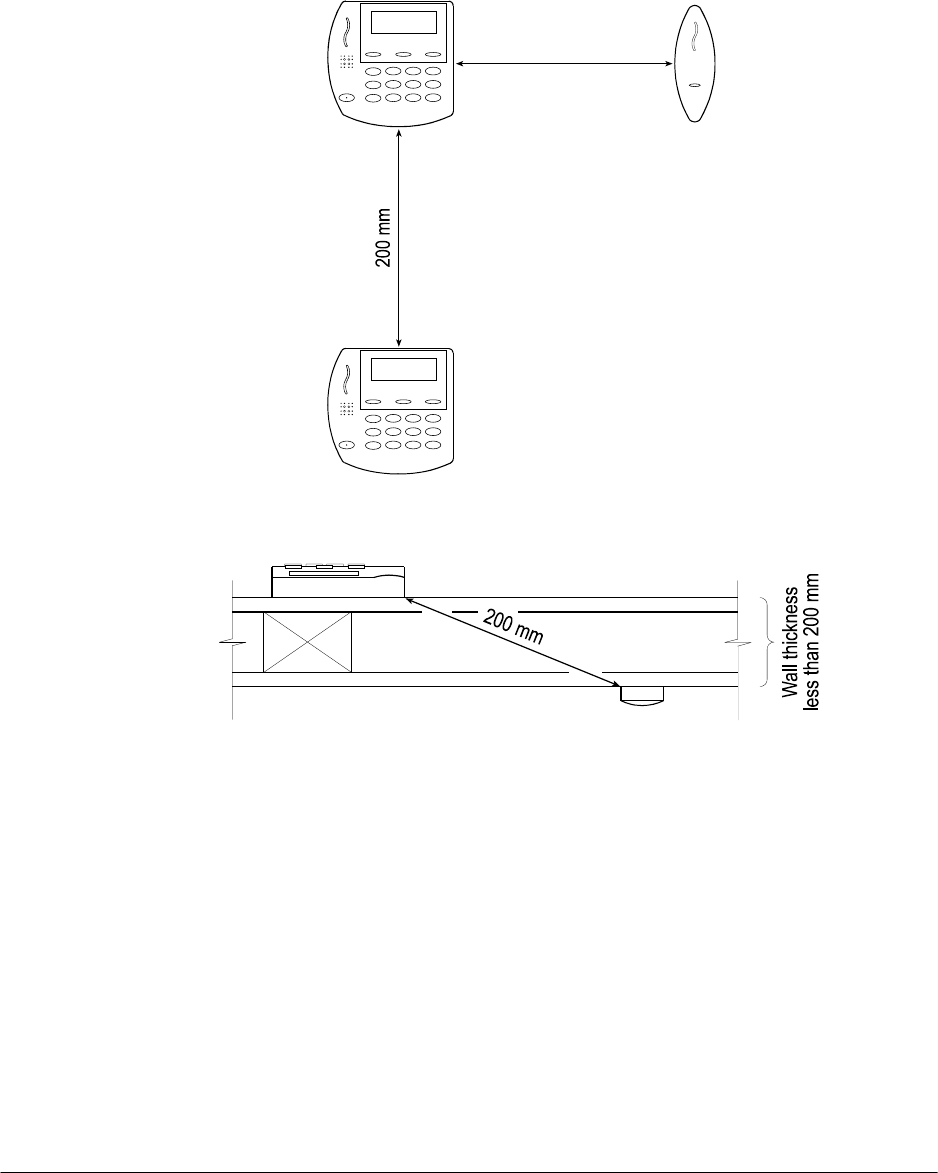
Distance between Proximity Readers
The distance separating any two proximity readers must not be less than
200mm in all directions.
200 mm
When mounting a proximity reader on an internal wall, check that any reader
fixed to the other side of the wall is not less than 200mm away.
Mounting
Note: The Prox Mifare Series (Teardrop) reader has been designed to metric
specifications. Therefore any imperial measurements provided are
approximate only.
The Prox Mifare Series (Teardrop) reader is designed to be mounted on any
solid flat surface. However installation on metal surfaces, particularly those
with a large surface area will reduce read range. The extent to which the range
is reduced will depend upon the type of metal used. To minimise this effect,
plastic spacers which may be mounted between the reader and the metal
surface are available (Part number C190980). Please contact your local Cardax
dealer for more information.
4 Part number 3E1100 R16
July 2010
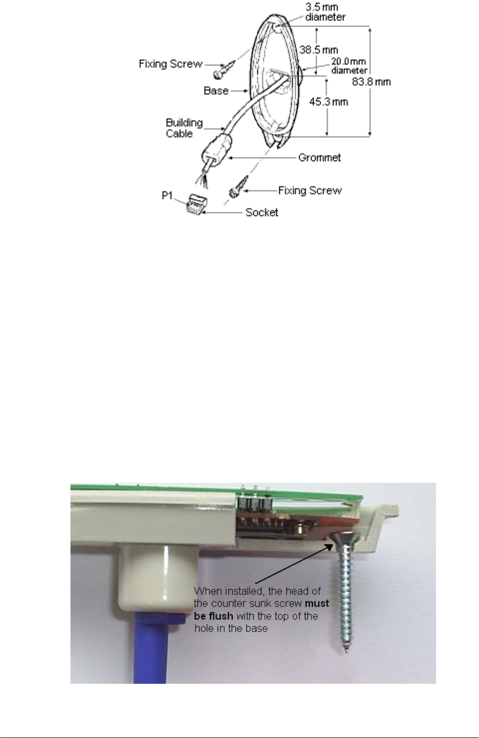
Note: The grommet through which the cables feed into the base of the Prox
Mifare Series (Teardrop) reader helps to keep the unit waterproof.
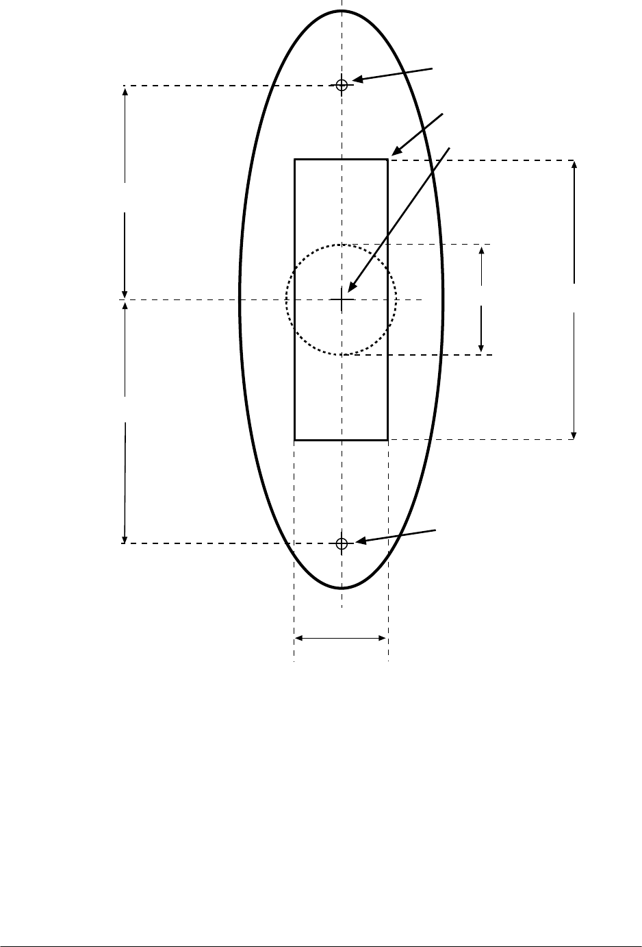
Using the mounting dimensions on the back of this Installation Note as a guide,
drill a 20 mm (3/4 inch) diameter hole for the base extrusion through or into the
mounting surface to a minimum depth of 40 mm (11/2 in).
Drill two pilot holes for the fixing screws.
Run the building cabling through the base and grommet.
Fit the base to the 20 mm (3/4 inch) hole and secure it to the mounting surface
using two of the fixing screws provided.
Note: The surface the reader is being attached to will determine which length
screws are most appropriate from those provided.
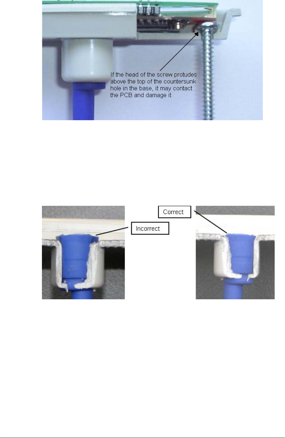
WARNING: You must use the screws provided, taking care not to over-
tighten them. Make sure that the heads of the counter sunk screws are flush
with the top of the holes in the base, and ensure there is clearance for the screw
that closes the base and facia together.
Failure to do this, and/or using other types of screws could interfere with the
electronics.
Part number 3E1100 R16 5
July 2010
Please note that the manufacturers warranty is voided if the electronics are
damaged as a result of the incorrect screws being used or installed incorrectly
to secure the base.
Push the socket back into the grommet.
Push the grommet and socket firmly back into the Prox Mifare Series
(Teardrop) reader base so that the top of the grommet is slightly below the
inside surface of the reader base.
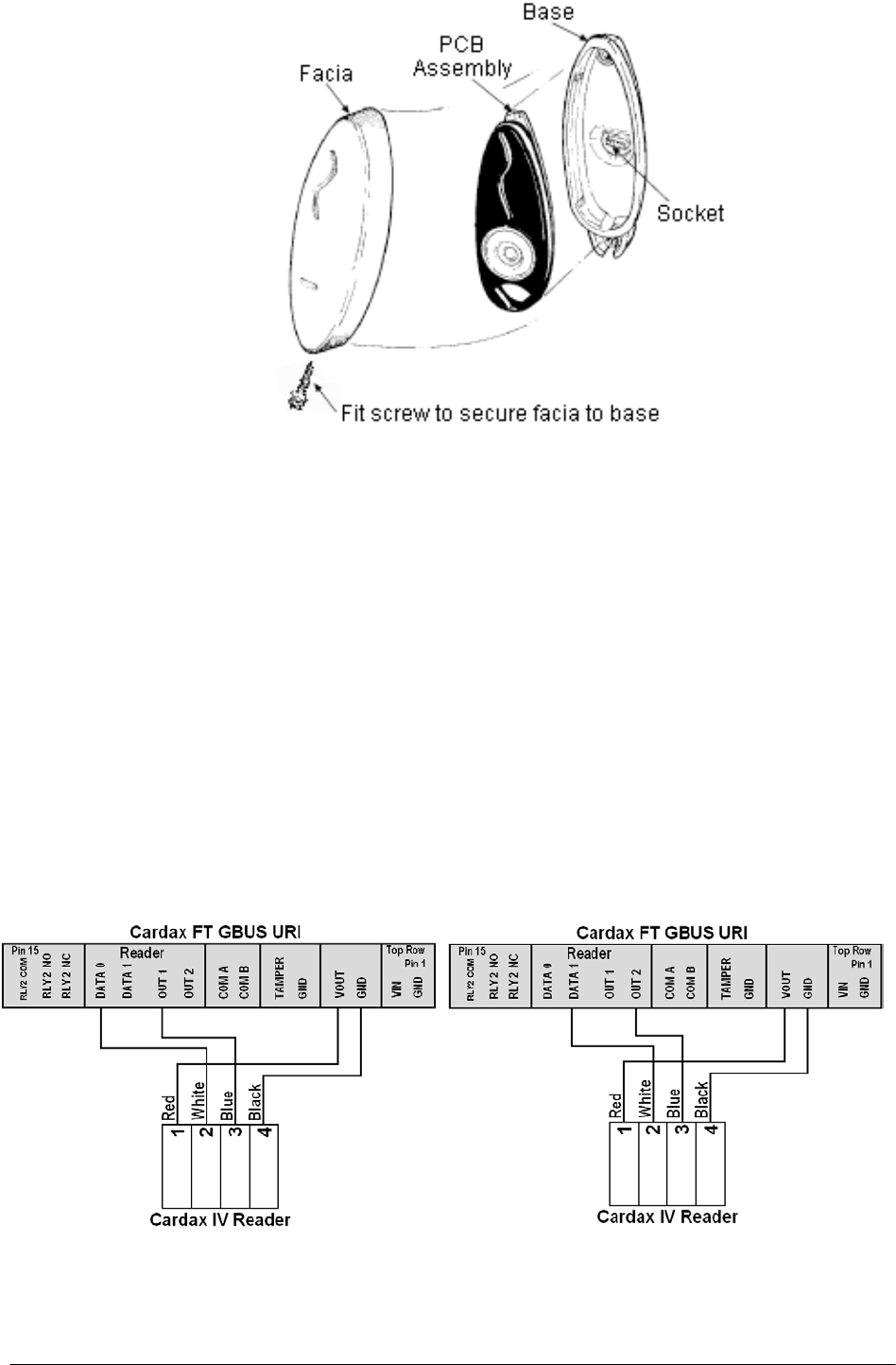
Install the PCB assembly into the base.
Fit the facia onto the base by clipping the small lip, inside the facia, over the
top edge of the base and holding the top, press the bottom of the facia down
over the base. If the cover does not fit easily, recheck the position of the
grommet and/or the reader. Then insert the M3 x 16 Torx Security Screw
(using an M3 Torx Post Security screwdriver) through the hole at the bottom of
the facia and into the threaded metal insert in the base to secure the facia.
Removal of the facia is a simple reversal of these steps.
6 Part number 3E1100 R16
July 2010
Connections
The Prox Mifare Series (Teardrop) reader connects to one of the following:
• Cardax FT GBUS URI
• Cardax FT Controller 3000-4R
• Cardax FT Controller 3000
Use the cable terminating tool to connect the cables to the socket as described
in the following sections.
Pin number 4 of the Prox Mifare Series (Teardrop) reader connector feeds into
the cable terminating tool first.
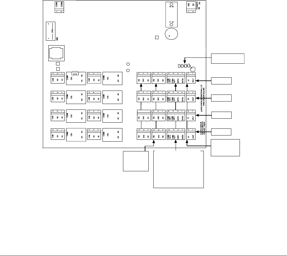
Connecting to the Cardax FT GBUS URI
Connect the cables to the socket as shown in either of the following diagrams.
Part number 3E1100 R16 7
July 2010
Connecting to the Cardax FT Controller 3000-4R or 3000
The Cardax FT Controller 3000-4R and 3000 both interface the following
types of reader into the Cardax FT Command Centre system:
• Cardax IV readers, including Prox Mifare Series (Teardrop) readers
• Wiegand readers
Each Cardax FT Controller 3000-4R can interface up to four Prox Mifare
Series (Teardrop) readers into the Cardax FT Command Centre system, and the
Cardax FT Controller 3000 can interface up to eight Prox Mifare Series
(Teardrop) readers.
The ports to which the Prox Mifare Series (Teardrop) reader can connect are
set up as groups, as follows:
• Two groups (numbered 1 and 2) on the Controller 3000-4R, and
• Four groups (numbered 1 to 4) on the Controller 3000.
Each group provides connection for two Prox Mifare Series (Teardrop) readers
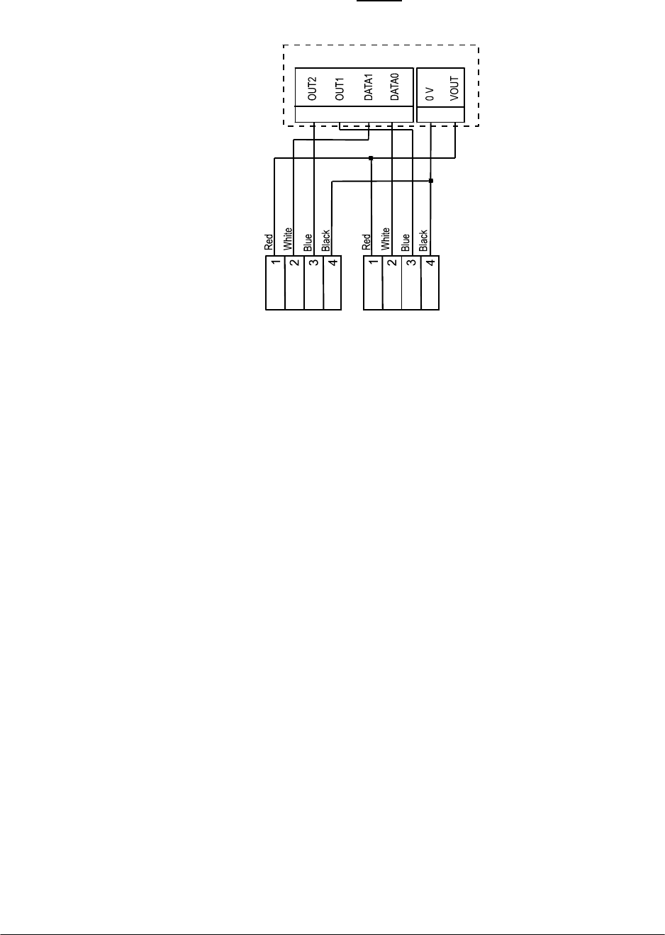
or other Cardax IV readers. Refer to the following diagram for the location of
the ports on the Cardax FT Controller 3000.
Note: Even though there are only two groups of ports on the Cardax FT
Controller 3000-4R, they are located in the same position.
P4
P3
P1
P2
P4
PF4
PF3
PF2
PE4
PE3
PE2
PF1 PE1
DETECTOR
LED
RS485
PA4
PA3
PA2
PA1
PA4
POW ER
OUT
PA3
POWER
OUT
PA2
POWER
OUT
PA1
POWE R
OUT
PB4
PB3
PB2
PB1
PC4
PC3
PC2
PC1
PD4
PD3
PD2
PD1
PC1
PC2
PC3
PC4PD4
PD3
PD2
PD1
PA1 to PA4
Power Out
pin 1 = power out
pin 2 = 0 V
Group 4
Group 3
Group 2
Group 1
PB1 to PB4
2 x Cardax IV Readers
per connector
Reader 1 = pins 1 & 3
Reader 2 = pins 2 & 4
Pin 1 = Reader 1 transmit
Pin 2 = Reader 2 transmit
Pin 3 = Reader 1 receive
Pin 4 = Reader 2 receive
J1 to J4
RS485
terminating resistors
PC1 to PC4
Inputs
pin 1 = Input 1
pin 2 = Ground
pin 3 = Input 2
8 Part number 3E1100 R16
July 2010
Make the connections from the Prox Mifare Series (Teardrop) reader to either
the Cardax FT Controller 3000-4R or 3000 as shown:
Cardax FT Controller 3000-4R or 3000
PA
Group
PB1 and PA1... to... PB2 and PA2 (3000-4R)
PB4 and PA4 (3000)
4 3 2 1 2 1
PB
Prox Mifare
Reader 1
Prox Mifare
Reader 2
Note: Within each group, you cannot mix Cardax IV readers with Wiegand
Readers. This is because connecting one Wiegand reader requires all four pins
on plug PB. For example, if you connect a Prox Mifare Series (Teardrop)
reader to Port 1 of Group 1, Port 2 of Group 1 can only connect to another
Cardax IV reader.
The terminating resistors (J1 for Group 1, J2 for Group 2, etc.) must NOT be
fitted for those groups to which Prox Mifare Series (Teardrop) readers are
connected.
Configuration
The Prox Mifare Series (Teardrop) reader is configured as a “Cardax IV
Reader” in Cardax FT Command Centre.
No specific initialisation or hardware configuration is required.

Part number 3E1100 R16 9
July 2010
Initialisation
Initialising with the Cardax FT GBUS URI
Refer to the Cardax FT GBUS Universal Reader Interface Installation Note
(Gallagher Part number 3E0690) for initialisation instructions.
Initialisation of the Cardax FT GBUS URI does not require prior connection to
the Prox Mifare Series (Teardrop) reader. The Prox Mifare Series (Teardrop)
reader will be operational as soon as it is:
• connected to a Cardax FT GBUS URI, and
• configured as a Cardax IV reader within the Cardax FT Command Centre
system.
Initialising with the Cardax FT Controller 3000-4R or 3000
Refer to the appropriate Installation Note for initialization instructions:
• Cardax FT Controller 3000-4R Installation Note (Part number 3E0510), or
• Cardax FT Controller 3000 Installation Note (Part number 3E1089)
Initialisation of the Cardax FT Controller 3000-4R or 3000 does not require
prior connection to the Prox Mifare Series (Teardrop) reader. The Prox Mifare
Series (Teardrop) reader will be operational as soon as it is:
• connected to a Cardax FT Controller 3000-4R or 3000, and
• configured as a Cardax IV reader within the Cardax FT Command Centre
system.
10 Part number 3E1100 R16
July 2010
Approvals and Standards
FCC
This equipment has been tested and found to comply with the limits for a Class B digital
device, pursuant to Part 15 of the FCC Rules. These limits are designed to provide
reasonable protection against harmful interference in a residential installation. This
equipment generates, uses and can radiate radio frequency energy and, if not installed
and used in accordance with the instructions, may cause harmful interference to radio
communications. However, there is no guarantee that interference will not occur in a
particular installation.
If this equipment does cause harmful interference to radio or television reception, which
can be determined by turning the equipment off and on, the user is encouraged to try to
correct the interference by one or more of the following measures:
• Reorient or relocate the receiving antenna.
• Increase the separation between the equipment and receiver.
• Connect the equipment into an outlet on a circuit different from that to which the
receiver is connected.
• Consult the dealer or an experienced radio/TV technician for help.
Note: Changes or modifications not expressly approved by Gallagher Group Limited
could void the user's authority to operate the equipment.
For UL Installations:
Refer to the section in the Cardax FT Command Centre Installation Note,
"Configuration Instructions to meet Underwriters Laboratory Inc Approved
Installations" for details covering specific requirements necessary to meet the specified
UL Licences. The following Release Note version(s) contain these details:
vEL5.21.xxx May 2009
vEL6.01.xxx October 2009
Installers must ensure these instructions are followed to ensure the installed system is
UL compliant.
UL temperature range tested and certified from -350C - +660C .
The voltage current values used and measured during testing are shown in the table
“Voltage / Current measurements” included in the Cardax FT Command Centre
Installation Note, "Configuration Instructions to meet Underwriters Laboratory Inc
Approved Installations".

Part number 3E1100 R16 11
July 2010
Technical specification
Routine maintenance and serviceable parts:
Not applicable for a Cardax Prox Mifare Series (Teardrop) reader
Cleaning:
The Cardax Prox Mifare Series (Teardrop) reader should only be cleaned
with clean, lint free, damp cloth
Power required:
Voltage 13.6 ± 15% V DC
Current 125mA
Reading range:
Up to 30mm (depending on card type and installation conditions)
Temperature range:
Operating temperature 00C to +550C
Environmental protection:
IP54
Dimensions:
105mm x 35mm x 17mm ((41/8” x 13/8” x 5/8 “ approx.)
Mounting:
Surface
Transmission frequency:
13.5MHz
12 Part number 3E1100 R16
July 2010
Mounting Dimensions
17 mm
39 mm
51 mm
51 mm
20 mm
Pilot hole
Pilot hole
20 mm hole
Slot