Gallagher Group C20024X FT IDT Mifare User Manual
Gallagher Group Ltd FT IDT Mifare Users Manual
Users Manual
Part number 3B3957 R8 1
June 2005
Installation Note
CAUTION
This equipment contains components that can be damaged by
electrostatic discharge. Ensure both you and the equipment are
earthed before beginning any servicing.
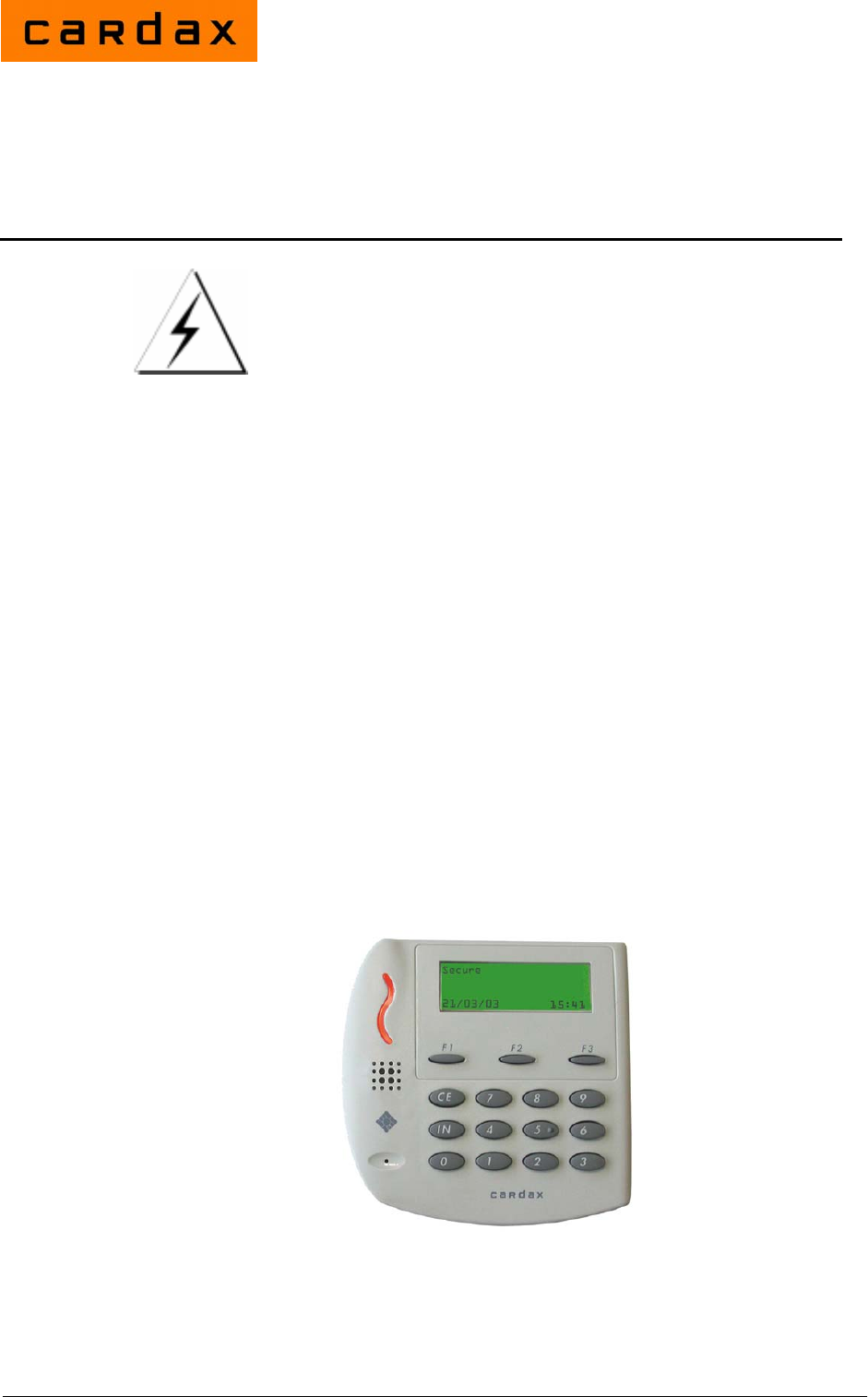
The Cardax FT Intelligent Door Terminal (Mifare Series)
The Cardax FT Intelligent Door Terminal Mifare Series (IDT) is a "remote"
proximity tag reader with text display and an inbuilt intercom.
The IDT can be installed as either an entry and/or exit reader, and the intercom
enables communication with the console operator.
The IDT has a back-lit keypad and an inbuilt Liquid Crystal Display (LCD).
The LCD can display both text and graphics to aid the Cardholder.
The IDT sends information to the Cardax FT Controller and acts upon
information sent from the Cardax FT Controller. The IDT itself does not make
any decisions.
A Cardax FT IDT Cover can be fitted over the IDT to prevent the IDT being
damaged by vandal attack and to increase protection against harsh weather.
Refer to the Prox Reader and IDT Covers Installation Note (part number
3C4589).
Cardax FT Intelligent
Door Terminal (Mifare Series)

2 Part number 3B3957 R8
June 2005
Before you begin
Shipment contents
Open the box and check that the following items have been supplied:
• 1 x Cardax FT IDT Mifare Base.
• 1 x Cardax FT IDT Mifare facia assembly (includes printed circuit boards,
processor, display and keypad).
• 1 x interconnect printed circuit board.
• 1 x copy of this installation note.
• 1 x cable assembly.
• 4 x pan-head self-tapping screws.
• 4 x screw caps.
• 1 x M4x12, tamper-resistant, Torx-head machine screw.
Software
The IDT requires version vMP3.00 or later of software code, which you can
download from your Cardax FT Command Centre Installation CD-ROM. If
the CD-ROM does not have vMP3.00 or later of IDT code on it, the code can
be downloaded from the Cardax website.
Once you have the correct IDT code, it then needs to be downloaded to the
IDT. To do this, refer to "Adding a new version of Device Software" for the
procedure, in the Cardax FT Command Centre User Guide (part number
C209000).
Power Supply Requirements
The IDT draws 300 mA from a 13.6 V ±15% DC supply. This means that with
the reader operating, the voltage measured across pins 1 and 4 on the
interconnect printed circuit board should be at least 11.6 V. It is recommended
that you dimension the cable to provide a minimum of 12 V at the IDT while it
is operating.
Use a well-regulated DC supply that incorporates good output filtering. Switch
mode power supplies may reduce the card read range due to the electrical noise
generated by the power supply switching circuits.
Building cabling
Run the building cabling before installing the IDT. Refer to Chapter 2 of
Cardax FT Installation Manual for cabling details.
Over short distances, you may run one cable carrying both the communications
and DC supply. Over long distances, run separate cables for the DC supply
and communications. In each case, verify that the correct supply voltage is
present at the IDT.
Part number 3B3957 R8 3
June 2005
RS485 communications
Use high-quality, low-capacitance, twisted-pair cable. Category 5 (CAT 5)
cable is suitable.
DC power
Ensure the cable size is adequate for correct operation of the IDT.
Mounting
Note: The IDT has been designed to metric specifications, therefore any
imperial measurements provided are approximate only.
The IDT is designed to mount on any solid, flat surface. The card read range is
reduced when the IDT is mounted on or near metal surfaces.
Height
The recommended mounting height for the IDT is 1100 mm, measured from
the centre of the facia to the floor.
Check your local regulations for any variations to this recommended height.
Installation
1. Fit the base as described in Fastening the base to the mounting surface
(on page 4).
2. Join the building cable to the connector tail and fit the Interconnect PCB as
described in Joining the cable (on page 4).
3. Set the IDT address as described in Setting the unit address (on page 5).
4. Fit the facia as described in Fitting the facia (on page 6).
4 Part number 3B3957 R8
June 2005
Fastening the base to the mounting surface
Note:
It is important that the base of the IDT is flush with, and tight against, the
mounting surface. If you are mounting the IDT on a rough surface, make the
surface as smooth as possible under the IDT and up to 25 mm (1 inch) around
the IDT.
1. Mark the position where the IDT is to be mounted.
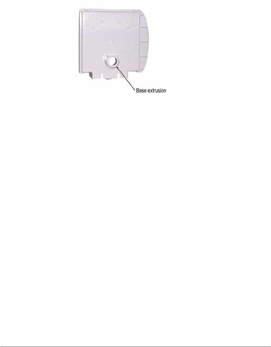
2. Drill a 20 mm (¾ inch) diameter hole through the mounting surface for the
base extrusion.
3. Optionally, drill four pilot holes for the four fixing screws.
Note:
Six possible mounting holes are provided in the base. Ensure the four you
chose will hold the IDT securely.
4. Pass the building cable through the hole in the base extrusion.
5. Press the base extrusion into the 20 mm hole. Use the four pan-head self-
tapping screws to fasten the base to the mounting surface.
6. Press a plastic cap into the socket over each screw head. The plastic caps
prevent water from entering the IDT through the fixing holes.
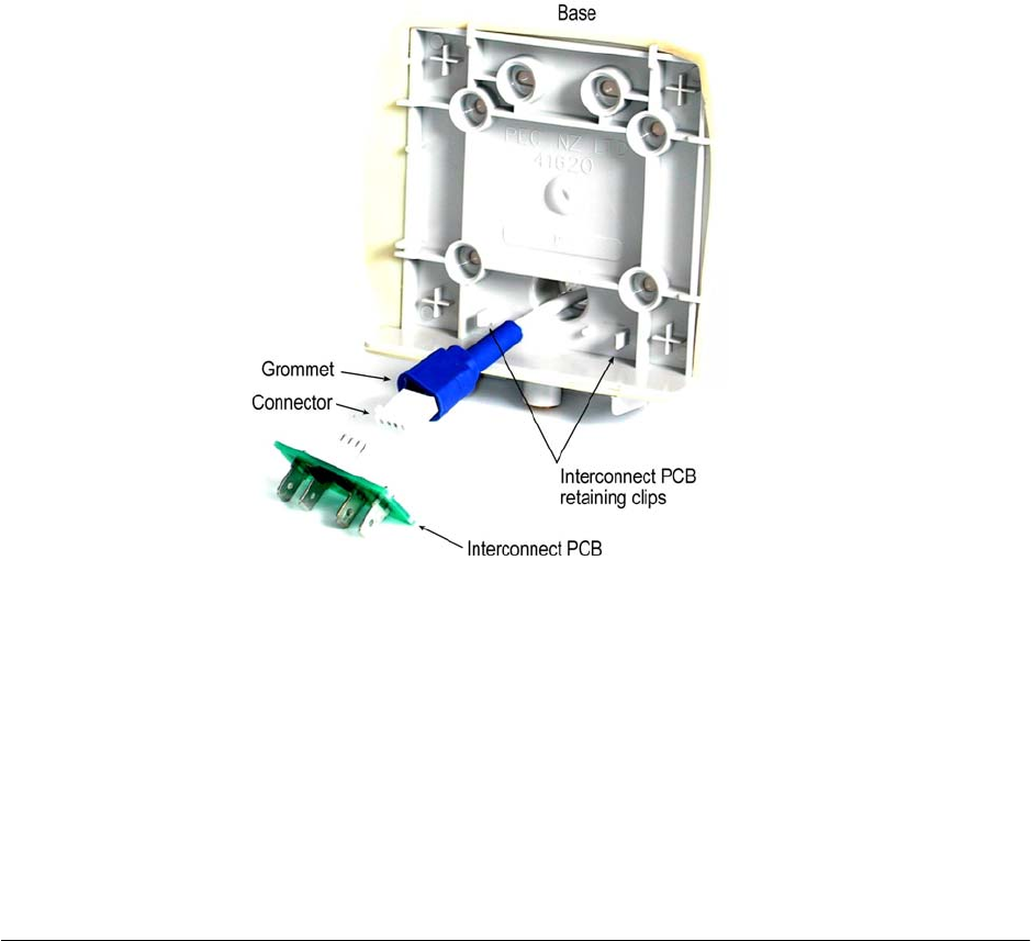
Joining the cable
1. Join the connector tail cable to the building cable.
Red: DC supply positive
White: RS485 communications cable
Blue: RS485 communications cable
Black: DC supply negative (0 V, GND)
Note:
The Cardax FT system does not require the RS485 communications cable
to be polarised. The DC supply must be connected to the correct terminals.
2. Press the connector into the grommet.
3. Press the connector onto the mating plug on the Interconnect PCB.
4. Push the Interconnect PCB back so that the connector and grommet slide
into the base extrusion. Press the Interconnect PCB until it locks under the
retaining clips.
Part number 3B3957 R8 5
June 2005
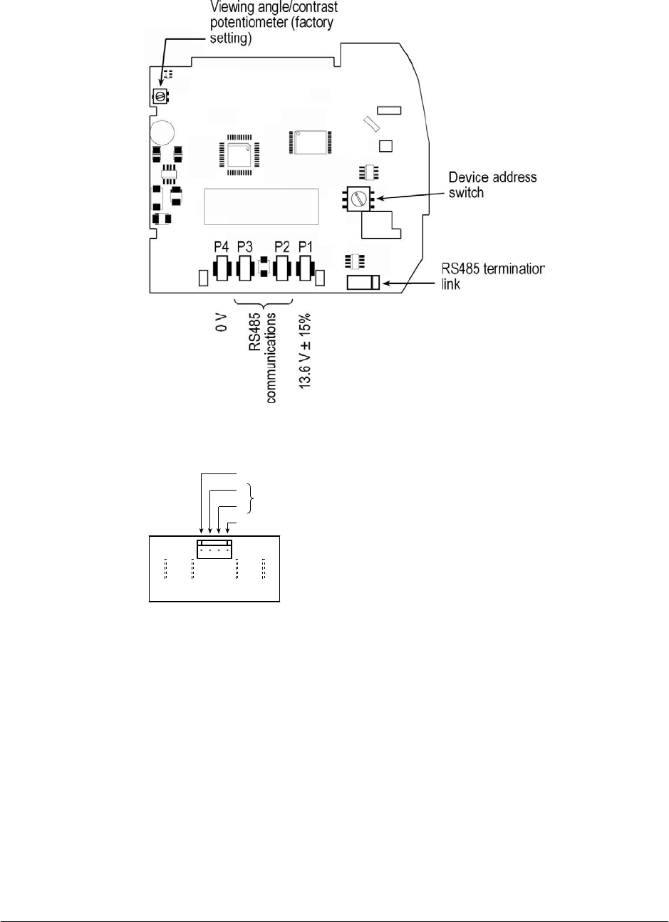
When to terminate the communications cable
If this IDT is the last unit on the communications cable run, verify that the
RS485 termination link is in place. If this IDT is not the last unit on the cable
run, remove the link. The location of this link is shown in Component layout
next.
Component layout
Interconnect PCB connections
P4 P3 P2 P1
4
3
2
1
RS485 communications
13.6 V ± 15%
0 V
Setting the unit address
A maximum of 16 IDTs can be connected to one Cardax FT Controller 5000.
Each must have its own address. Usually the address is set at the time the site
is commissioned.
The address assigned to the IDT must match that set up at the Cardax FT
Command Centre server. Refer to the Cardax FT Command Centre
documentation.
1. On the PCB inside the facia, locate the Unit Address switch.
6 Part number 3B3957 R8
June 2005
2. Use a small screwdriver to set the switch to the required address number.
The Unit Address switch is calibrated for hexadecimal numbers. Use the
table to convert an IDT address to the corresponding switch setting.
IDT address 0 1 2 3 4 5 6 7 8 9 10 11 12 13 14 15
Switch calibration 0 1 2 3 4 5 6 7 8 9 A B C D E F
Adjustment of the viewing angle
The Liquid Crystal Display (LCD) in the IDT is temperature compensated to
maintain optimum contrast. The viewing angle is set in the factory. Do not
attempt to change the setting of the Viewing Angle/Contrast potentiometer.
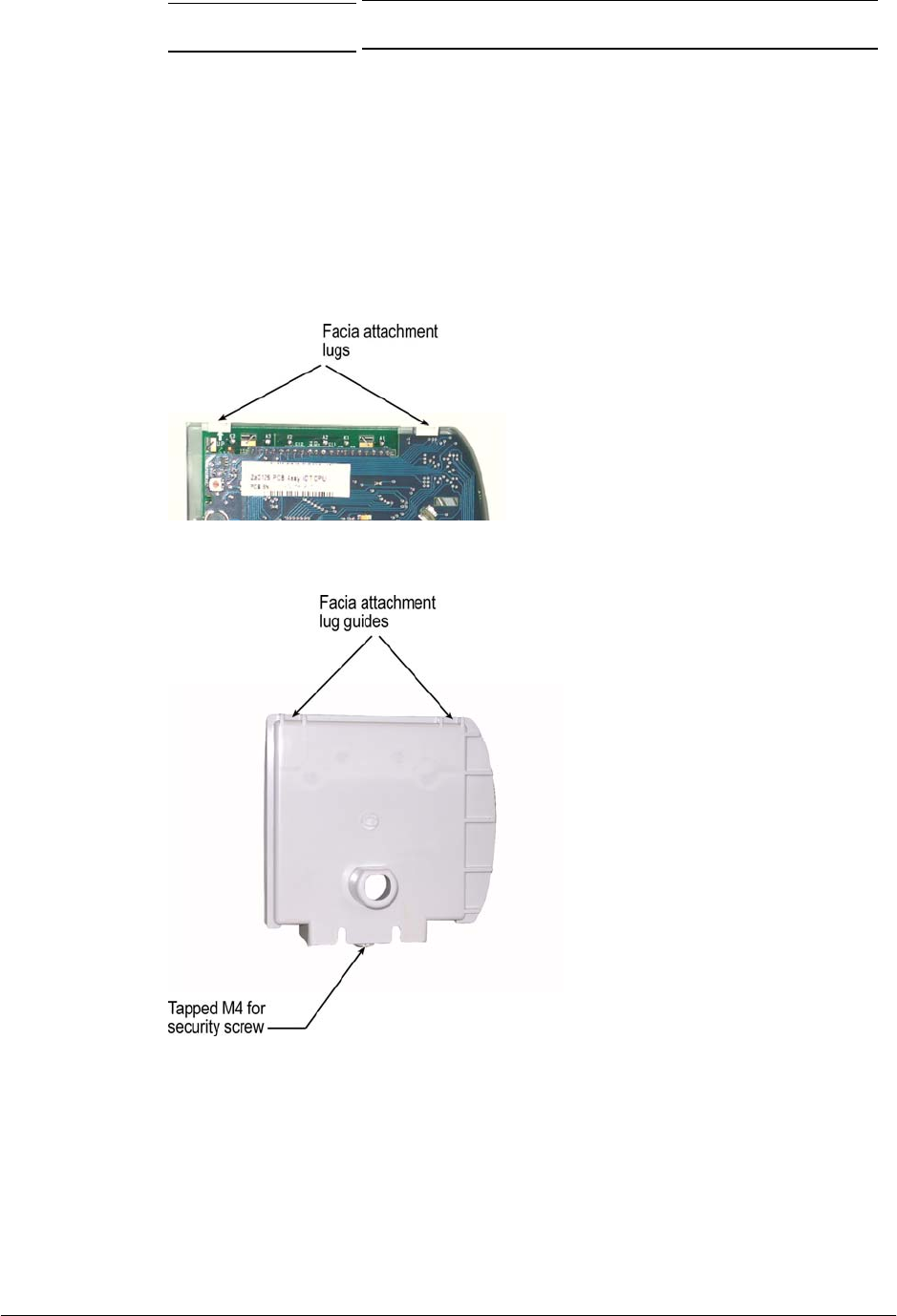
Fitting the facia
1. Verify that the Interconnect PCB is seated in the clips in the base.
2. Slide the facia attachment lugs of the facia into the guides at the rear of the
base.
3. On the front of the facia, press down on the Cardax FT label until the
security screw hole lines up with the threaded hole underneath the base.
4. Pass the M4 security screw through the hole in the facia. Use a tamper-
resistant Torx-head tool to drive the security screw into the threaded hole in
the base.

Part number 3B3957 R8 7
June 2005
Removing the facia
1. Using a tamper-resistant Torx-head tool, remove the M4 security screw
from the underside of the facia.
2. Pull the base of the facia away from the base plate.
3. Slide the facia's attachment lugs out of the guides at the rear of the base
plate.
Technical Specifications
Routine maintenance and serviceable parts
Not applicable for the IDT.
Cleaning
Wipe the IDT with a lint-free damp cloth.
DC supply
Voltage 13.6 V ± 15%
Current 300 mA
Environment
Operating temperature -10° C to 55° C
Humidity 95%, non-condensing.
Mounting height
1100 mm (3 feet) to centre.

8 Part number 3B3957 R8
June 2005
Approvals and Standards
This equipment has been tested and found to comply with the limits for a Class
B digital device, pursuant to Part 15 of the FCC Rules. These limits are
designed to provide reasonable protection against harmful interference in a
residential installation. This equipment generates, uses and can radiate radio
frequency energy and, if not installed and used in accordance with the
instructions, may cause harmful interference to radio communications.
However, there is no guarantee that interference will not occur in a particular
installation.
If this equipment does cause harmful interference to radio or television
reception, which can be determined by turning the equipment off and on, the
user is encouraged to try to correct the interference by one or more of the
following measures:
• Reorient or relocate the receiving antenna.
• Increase the separation between the equipment and receiver.
• Connect the equipment into an outlet on a circuit different from that to
which the receiver is connected.
• Consult the dealer or an experienced radio/TV technician for help.
Note: Changes or modifications not expressly approved by Gallagher Security
Management Systems could void the user's authority to operate the
equipment.
ACN: 002132943